EP1568496A1 - Aufzeichnungsgerät - Google Patents
Aufzeichnungsgerät Download PDFInfo
- Publication number
- EP1568496A1 EP1568496A1 EP05003402A EP05003402A EP1568496A1 EP 1568496 A1 EP1568496 A1 EP 1568496A1 EP 05003402 A EP05003402 A EP 05003402A EP 05003402 A EP05003402 A EP 05003402A EP 1568496 A1 EP1568496 A1 EP 1568496A1
- Authority
- EP
- European Patent Office
- Prior art keywords
- recording
- output terminals
- drive electrodes
- rows
- data
- Prior art date
- Legal status (The legal status is an assumption and is not a legal conclusion. Google has not performed a legal analysis and makes no representation as to the accuracy of the status listed.)
- Granted
Links
- 238000003860 storage Methods 0.000 claims description 21
- 230000014759 maintenance of location Effects 0.000 claims description 13
- 239000003086 colorant Substances 0.000 claims description 11
- 238000006243 chemical reaction Methods 0.000 claims description 6
- 239000000976 ink Substances 0.000 description 51
- 238000010926 purge Methods 0.000 description 8
- 230000005540 biological transmission Effects 0.000 description 3
- 230000004044 response Effects 0.000 description 3
- 239000002699 waste material Substances 0.000 description 3
- 238000010586 diagram Methods 0.000 description 2
- 238000004519 manufacturing process Methods 0.000 description 2
- 238000012986 modification Methods 0.000 description 2
- 230000004048 modification Effects 0.000 description 2
- RYGMFSIKBFXOCR-UHFFFAOYSA-N Copper Chemical compound [Cu] RYGMFSIKBFXOCR-UHFFFAOYSA-N 0.000 description 1
- 239000000853 adhesive Substances 0.000 description 1
- 230000001070 adhesive effect Effects 0.000 description 1
- 239000011889 copper foil Substances 0.000 description 1
- 229920001721 polyimide Polymers 0.000 description 1
- 238000003825 pressing Methods 0.000 description 1
- 229910000679 solder Inorganic materials 0.000 description 1
Images



Classifications
-
- B—PERFORMING OPERATIONS; TRANSPORTING
- B41—PRINTING; LINING MACHINES; TYPEWRITERS; STAMPS
- B41J—TYPEWRITERS; SELECTIVE PRINTING MECHANISMS, i.e. MECHANISMS PRINTING OTHERWISE THAN FROM A FORME; CORRECTION OF TYPOGRAPHICAL ERRORS
- B41J2/00—Typewriters or selective printing mechanisms characterised by the printing or marking process for which they are designed
- B41J2/005—Typewriters or selective printing mechanisms characterised by the printing or marking process for which they are designed characterised by bringing liquid or particles selectively into contact with a printing material
- B41J2/01—Ink jet
- B41J2/015—Ink jet characterised by the jet generation process
- B41J2/04—Ink jet characterised by the jet generation process generating single droplets or particles on demand
- B41J2/045—Ink jet characterised by the jet generation process generating single droplets or particles on demand by pressure, e.g. electromechanical transducers
- B41J2/04501—Control methods or devices therefor, e.g. driver circuits, control circuits
- B41J2/04581—Control methods or devices therefor, e.g. driver circuits, control circuits controlling heads based on piezoelectric elements
-
- B—PERFORMING OPERATIONS; TRANSPORTING
- B41—PRINTING; LINING MACHINES; TYPEWRITERS; STAMPS
- B41J—TYPEWRITERS; SELECTIVE PRINTING MECHANISMS, i.e. MECHANISMS PRINTING OTHERWISE THAN FROM A FORME; CORRECTION OF TYPOGRAPHICAL ERRORS
- B41J2/00—Typewriters or selective printing mechanisms characterised by the printing or marking process for which they are designed
- B41J2/005—Typewriters or selective printing mechanisms characterised by the printing or marking process for which they are designed characterised by bringing liquid or particles selectively into contact with a printing material
- B41J2/01—Ink jet
- B41J2/015—Ink jet characterised by the jet generation process
- B41J2/04—Ink jet characterised by the jet generation process generating single droplets or particles on demand
- B41J2/045—Ink jet characterised by the jet generation process generating single droplets or particles on demand by pressure, e.g. electromechanical transducers
- B41J2/04501—Control methods or devices therefor, e.g. driver circuits, control circuits
- B41J2/04541—Specific driving circuit
-
- B—PERFORMING OPERATIONS; TRANSPORTING
- B41—PRINTING; LINING MACHINES; TYPEWRITERS; STAMPS
- B41J—TYPEWRITERS; SELECTIVE PRINTING MECHANISMS, i.e. MECHANISMS PRINTING OTHERWISE THAN FROM A FORME; CORRECTION OF TYPOGRAPHICAL ERRORS
- B41J2/00—Typewriters or selective printing mechanisms characterised by the printing or marking process for which they are designed
- B41J2/005—Typewriters or selective printing mechanisms characterised by the printing or marking process for which they are designed characterised by bringing liquid or particles selectively into contact with a printing material
- B41J2/01—Ink jet
- B41J2/135—Nozzles
- B41J2/14—Structure thereof only for on-demand ink jet heads
- B41J2/14201—Structure of print heads with piezoelectric elements
- B41J2/14209—Structure of print heads with piezoelectric elements of finger type, chamber walls consisting integrally of piezoelectric material
-
- B—PERFORMING OPERATIONS; TRANSPORTING
- B41—PRINTING; LINING MACHINES; TYPEWRITERS; STAMPS
- B41J—TYPEWRITERS; SELECTIVE PRINTING MECHANISMS, i.e. MECHANISMS PRINTING OTHERWISE THAN FROM A FORME; CORRECTION OF TYPOGRAPHICAL ERRORS
- B41J2/00—Typewriters or selective printing mechanisms characterised by the printing or marking process for which they are designed
- B41J2/005—Typewriters or selective printing mechanisms characterised by the printing or marking process for which they are designed characterised by bringing liquid or particles selectively into contact with a printing material
- B41J2/01—Ink jet
- B41J2/135—Nozzles
- B41J2/14—Structure thereof only for on-demand ink jet heads
- B41J2/14201—Structure of print heads with piezoelectric elements
- B41J2/14209—Structure of print heads with piezoelectric elements of finger type, chamber walls consisting integrally of piezoelectric material
- B41J2002/14217—Multi layer finger type piezoelectric element
-
- B—PERFORMING OPERATIONS; TRANSPORTING
- B41—PRINTING; LINING MACHINES; TYPEWRITERS; STAMPS
- B41J—TYPEWRITERS; SELECTIVE PRINTING MECHANISMS, i.e. MECHANISMS PRINTING OTHERWISE THAN FROM A FORME; CORRECTION OF TYPOGRAPHICAL ERRORS
- B41J2/00—Typewriters or selective printing mechanisms characterised by the printing or marking process for which they are designed
- B41J2/005—Typewriters or selective printing mechanisms characterised by the printing or marking process for which they are designed characterised by bringing liquid or particles selectively into contact with a printing material
- B41J2/01—Ink jet
- B41J2/135—Nozzles
- B41J2/14—Structure thereof only for on-demand ink jet heads
- B41J2/14201—Structure of print heads with piezoelectric elements
- B41J2/14209—Structure of print heads with piezoelectric elements of finger type, chamber walls consisting integrally of piezoelectric material
- B41J2002/14225—Finger type piezoelectric element on only one side of the chamber
-
- B—PERFORMING OPERATIONS; TRANSPORTING
- B41—PRINTING; LINING MACHINES; TYPEWRITERS; STAMPS
- B41J—TYPEWRITERS; SELECTIVE PRINTING MECHANISMS, i.e. MECHANISMS PRINTING OTHERWISE THAN FROM A FORME; CORRECTION OF TYPOGRAPHICAL ERRORS
- B41J2/00—Typewriters or selective printing mechanisms characterised by the printing or marking process for which they are designed
- B41J2/005—Typewriters or selective printing mechanisms characterised by the printing or marking process for which they are designed characterised by bringing liquid or particles selectively into contact with a printing material
- B41J2/01—Ink jet
- B41J2/135—Nozzles
- B41J2/14—Structure thereof only for on-demand ink jet heads
- B41J2002/14459—Matrix arrangement of the pressure chambers
-
- B—PERFORMING OPERATIONS; TRANSPORTING
- B41—PRINTING; LINING MACHINES; TYPEWRITERS; STAMPS
- B41J—TYPEWRITERS; SELECTIVE PRINTING MECHANISMS, i.e. MECHANISMS PRINTING OTHERWISE THAN FROM A FORME; CORRECTION OF TYPOGRAPHICAL ERRORS
- B41J2/00—Typewriters or selective printing mechanisms characterised by the printing or marking process for which they are designed
- B41J2/005—Typewriters or selective printing mechanisms characterised by the printing or marking process for which they are designed characterised by bringing liquid or particles selectively into contact with a printing material
- B41J2/01—Ink jet
- B41J2/135—Nozzles
- B41J2/14—Structure thereof only for on-demand ink jet heads
- B41J2002/14491—Electrical connection
Definitions
- the present invention relates in general to a recording apparatus, and more particularly to a recording apparatus which has recording elements arranged in a plurality of rows and which is arranged to perform a recording operation by driving the recording elements on the basis of recording information supplied to the apparatus.
- the recording head of an inkjet recording apparatus is equipped with a plate-type piezoelectric actuator unit having recording elements which are activated to eject color inks through nozzles. That is, each of the recording elements is activated to eject the ink of the corresponding color through a corresponding one of the nozzles which are formed in the recording head to be arranged in a plurality of rows.
- a surface of the piezoelectric actuator unit there are formed surface electrodes which are electrically connected to drive electrodes, so that drive signals driving the respective recording elements can be supplied to the drive electrodes via the surface electrodes.
- a flexible wiring board is provided to be connected to an upper portion of the piezoelectric actuator unit, such that the wiring board is elongated or extends in a direction parallel to the rows of the nozzles.
- an IC chip hereinafter referred to as "converter" for outputting the drive signals.
- the converter has output terminals connected to the respective surface electrodes via a wiring pattern which is formed on the flexible wiring board and which is provided by conductive lines or wires each connecting a corresponding one of the output terminals to a corresponding one of the surface electrodes.
- the conductive wires are arranged to extend substantially straightly in parallel with the rows of the nozzles. In this arrangement, the output terminals and the conductive wires are grouped into a plurality of groups corresponding to the respective rows of the nozzles.
- U.S. Patent No. 6,260,937 discloses a control to transmit recording information to the converter, which control can be carried out in a recording apparatus such as the above-described inkjet recording apparatus.
- the inkjet recording apparatus has image-data buffer storages each capable of storing a portion of the recording information which is related to a corresponding one of the ink colors.
- the image-data buffer storages are connected to respective read-out circuits.
- the portions of the recording information relating to the respective ink colors are transmitted in sequence over a single path to the converter.
- the converter coverts the serially transmitted information into parallel signals, and then applies the parallel signals as drive signals to the respective drive electrodes, so that the inks are ejected through the respective nozzles onto the recording medium whereby the recording operation is performed on the recording medium.
- a widthwise direction of the wiring board corresponds to a direction perpendicular to the rows of the nozzles, namely, corresponds to a widthwise direction of the recording head rather than a lengthwise direction of the recording head. Therefore, there is a limitation as to the number of the conductive wires formable on the wiring board, making it difficult to increase the number of the nozzles. Where the number of the nozzles is required to be increased, the recording apparatus requires to be provided with a plurality of recording heads. The provision of the plurality of recording heads problematically leads to an increase in cost required for manufacturing the apparatus and an increase in overall size of the apparatus.
- the flexible wiring board has to be arranged to have a plurality of layers so that the output terminals of each family can be connected to the surface electrodes of the corresponding row via one of a plurality of wiring patterns which are formed on the respective layers, or (ii) a logic circuit has to be provided within the converter or between the output terminals and the surface electrodes, for changing a positional relationship between each of the output terminals and a corresponding one of the surface electrodes.
- the manufacturing cost is inevitably increased.
- the present invention was made in view of the background prior art discussed above. It is therefore an object of the invention to provide a recording apparatus which has recording elements arranged in a plurality of rows and which has simplified circuit and wiring arrangements for transmission of recording information.
- the object may be achieved according to the principle of the invention, which provides a recording apparatus for performing a recording operation on a recording medium on the basis of recording information.
- This recording apparatus includes: (a) a recording head having (a-i) recording elements which are arranged in a plurality of rows, and (a-ii) drive electrodes which are arranged in a plurality of rows and which receive respective drive signals to drive the respective recording elements; (b) a converter which converts serially transmitted data representative of the recording information, into parallel signals serving as the drive signals applied to the drive electrodes; and (c) a controller which transmits the data serially to the converter.
- the converter has a plurality of output terminals which are connected to the respective drive electrodes arranged in the plurality of rows, so that the parallel signals can be transmitted to the drive electrodes through the respective output terminals.
- the output terminals are connected to the respective drive electrodes across the plurality of rows of the drive electrodes, and are arranged in a row in an order generally corresponding to arrangement of the drive electrodes from one end of the recording head to the other end thereof.
- the controller transmits the data representative of the recording information to the converter serially in association with the drive electrodes, in an order corresponding to arrangement of the output terminals.
- the recording head has the recording elements arranged in the plurality of rows and the drive electrodes arranged in the plurality of rows so as to correspond to the respective recording elements.
- the drive electrodes receive the respective drive signals to drive the respective recording elements.
- the converter converts the serially transmitted data into the parallel signals serving as the drive signals applied to the drive electrodes.
- the output terminals of the converter are connected to the respective electrodes across the plurality of rows of the drive electrodes, and are arranged in the row in the order generally corresponding to the arrangement of the drive electrodes from the one end of the recording head to the other end thereof. Further, the controller transmits the data representative of the recording information to the converter serially in association with the drive electrodes, in the order corresponding to the arrangement of the output terminals.
- the data is serially transmitted by the controller to the converter in the order generally corresponding to the arrangement of the drive electrodes from the one end of the recording head to the other end thereof.
- the parallel signals which are obtained from the data thus transmitted, can be applied as the drive signals directly to the drive electrodes.
- an inkjet recording apparatus in the form of a inkjet printer 1 which includes: ink cartridges 2 filled with respective color inks; mount portions 3 on which the ink cartridges 2 are removably mounted; ink supplying tubes 4; ink tanks 5 for storing the inks supplied from the ink cartridges 2 through the respective ink supplying tubes 4; a recording head 7 for ejecting the inks stored in the ink tanks 5, toward a recording medium (e.g., paper sheet) 6; a carriage 9 for carrying a recording head unit 8 which is principally constituted by the ink tanks 5 and the recording head 7; a pair of guide rods 10 for guiding the carriage 9 which is reciprocated along the guide rods 10; a feed device 11 for feeding the recording medium 6 in a predetermined direction; and a purging device 12.
- ink cartridges 2 filled with respective color inks
- mount portions 3 on which the ink cartridges 2 are removably mounted ink supplying tubes 4
- ink tanks 5 for storing the in
- the ink cartridges 2, containing the respective color inks (e.g., cyan, magenta, yellow and black inks), are provided in the inkjet printer 1, for enabling the printer 1 to perform a full-color printing operation.
- Each ink cartridge 2 can be mounted in the corresponding mount portion 3, by simply pressing the ink cartridge 2 into the mount portion 3 in a direction as indicated by arrow X as shown in Fig. 1.
- Each mount portion 3 has a base portion 3a and a pair of guide portions 3b which extend from respective opposite end portions of the base portion 3a.
- An ink supplying pipe 13 and an air introducing pipe 14 are provided to be project from the base portion 3a, so that the ink stored in the ink cartridge 2 can be supplied to an exterior of the ink cartridge 2 through the ink supplying pipe 13 while an outside air can be introduced into the ink cartridge 2 through the air introducing pipe 14.
- the ink supplying pipe 13 is connected at its one end portion to the ink supplying tube 4, so as to be held in communication with the ink tank 5 through the ink supplying tube 4.
- the air introducing pipe 14 is connected at its one end portion to an air introducing tube 15, so as to be held in communication with outside air through the air introducing tube 15.
- the purging device 12 is disposed in a purging operation position located outside a printing area (within which the recording head 7 is moved for achieving the printing operation), and is opposed to the recording head 7 when the recording head 7 is positioned in the purging operation position.
- the purging device 12 has a purge cap 12a, a waste ink tube 12b and a pump 12c.
- the purge cap 12a is provided to cover a nozzle-defining surface of the recording head 7 in which nozzles 16k, 16c, 16y, 16m open (see Fig. 4).
- the pump 12 is activated to suck poor-quality or waste inks from the nozzles 16k, 16c, 16y, 16m through the waste ink tube 12b which is held in communication with the purge cap 12a.
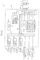
- the inkjet printer 1 is provided with a control device including a controller board in the form of a main control board 20 mounted on a main body of the inkjet printer 1, and a carriage board 21 mounted on the carriage 9.
- the main control board 20 incorporates: a CPU (one-chip microcomputer) 22 serving as a main control portion; a ROM 23 storing various control programs 23a executed by the CPU 22 and various fixed data 23b used by the CPU 22; a RAM 24 provided by a rewritable volatile memory for temporarily storing various data; an image memory 25; a G/A (gate array) 26; and an I/F (interface) 27 through which various data are transmitted between the main control board 20 and an external device such as a host computer (not shown).
- a CPU one-chip microcomputer
- the CPU 22 functioning as an arithmetic and logic device is operable to perform various operations according to the control programs 23a stored in the ROM 23.
- the CPU 22 is further operable to generate a printing timing signal and a resetting signal, and apply these signals to the G/A 26.
- a CR-motor driver circuit 29 for driving a carriage drive motor (CR motor) 28 to move the carriage 9
- a LF-motor driver circuit 31 for driving a sheet feeding motor (LF motor) 30 to feed the recording medium 6
- a pump driver circuit 32 for driving the pump 12c
- a paper-presence sensor 33 for detecting a leading edge of the recording medium 6
- a zero-point sensor 34 for confirming that the carriage 9 is positioned in its zero-point (home) when it is returned to the zero-point
- an operator's control panel 35 through which the user enters desired commands (e.g., printing command) into the CPU 22.
- the various elements thus connected to the CPU 22 are controlled by the CPU 22.
- the image memory 25 has a buffer section for temporarily storing recording information transmitted from the external device via the I/F 27.
- This buffer section includes information storages in the form of image-data buffer storages each storing a portion of the recording information which is related to a corresponding one of the recording ink colors.
- As the image-data buffer storages there are a black-color-image-data buffer storage 25k, a cyan-color-image-data buffer storage 25c, a yellow-color-image-data buffer storage 25y and a magenta-color-image-data buffer storage 25m.
- the G/A 26 serves to cause the image memory 25 to store therein the recording information transmitted from the external device via the I/F 27. Further, the G/A 26 generates a data-reception interruption signal on the basis of data transferred from the host computer or other external device via the I/F 27, and then transfers the generated signal to the CPU 22.
- the G/A 26 includes a controller 26a which reads out the recording information from the buffer storages 25k, 25c, 25y, 25m and serially transmits the recording information to the carriage board 21.
- the G/A 26 outputs recording data DATA representative of the recording information read out by the controller 26a, a transfer clock TCK for synchronization with the recording data DATA, a strobe signal STB, and an ejection timing signal CLK (which is outputted at a predetermined cycle).
- the outputted data and signals are transmitted through respective signal lines to the carriage board 21 which is equipped with a head driver. Further, a power for driving a converter 38 is supplied to the carriage board 21 through a power line.
- the G/A 26 and the carriage board 21 are connected to each other through a flexible wiring board 44, so that the above-described data and signals can be transmitted between the G/A 26 and the carriage board 21 through the flexible wiring board 44.
- the CPU 22 is connected to the ROM 23, RAM 24 and G/A 26 via a bus line 36.
- the carriage board 21 serves as a relay circuit board which connects the main control board 20 and the recording head 7.
- the carriage board 21 and the recording head 7 are connected to each other through a flexible wiring board 37 which is provided by a polyimide film having a thickness of 50-150 ⁇ m and a copper foil wiring pattern formed on the film.
- a flexible wiring board 37 which is provided by a polyimide film having a thickness of 50-150 ⁇ m and a copper foil wiring pattern formed on the film.
- an IC chip serving as the converter 38 for converting the serially transmitted recording data DATA into parallel signal data, and forming drive signals based on the transmitted data DATA.
- the converter 38 outputs the drive signals for driving a piezoelectric actuator unit which is described below.
- the flexible wiring board 37 is connected at its end terminals 37a with the carriage board 21.
- the nozzles 16k, 16c, 16y, 16m are arranged in four rows which are parallel with each other. Described specifically, the nozzles 16k, through which the black color ink is to be ejected, are located in the leftmost one of the rows, as seen in Fig. 4. The nozzles 16c, through which the cyan color ink is to be ejected, are located in the second leftmost one of the rows. The nozzles 16y, through which the yellow color ink is to be ejected, are located in the second rightmost one of the rows.
- the nozzles 16m, through which the magenta color ink is to be ejected, are located in the rightmost one of the rows. It is noted that a direction perpendicular to the rows (i.e., lateral direction as seen Fig. 4) corresponds to a direction in which the carriage 9 is movable (see Fig. 1).
- the recording head 7 includes a plate-type piezoelectric actuator unit 7b and a cavity unit 7a which is constituted by a plurality of plates which are superposed on each other. As shown in Fig. 3, the cavity unit 7a has ink inlets 17k, 17c, 17y, 17m which open in its upper surface.
- Each of the ink inlets 17k, 17c, 17y, 17m is held in communication with manifold passages, so that the ink of the corresponding color can be distributed into a plurality of pressure chambers via the respective manifold passages, and can be ejected through the nozzles 16k, 16c, 16y, 16m which are held in communication with the plurality of pressure chambers.
- the piezoelectric actuator unit 7b has a plurality of pressure generators, i.e., recording elements each of which is piezoelectrically activatable or deformable to change a volume of a corresponding one of the pressure chambers.
- the actuator unit 7b further has drive electrodes 18k, 18c, 18y, 18m which are disposed on its upper surface and are connected to the respective recording elements, and a plurality of common electrodes 19 each of which is common to ones of the drive electrodes 18k, 18c, 18y, 18m as individual electrodes.
- the recording elements, whose number corresponds to that of the nozzles 16k, 16c, 16y, 16m, are arranged in the rows so as to correspond to the respective nozzles 16k, 16c, 16y, 16m.
- the drive signals are applied to selected ones of the drive electrodes 18k, 18c, 18y, 18m, whereby the recording elements corresponding to the selected drive electrodes 18k, 18c, 18y, 18m are activated or deformed to pressurize the inks within the corresponding pressure chambers, for ejecting the pressurized inks from the pressure chambers.
- the flexible wiring board 37 is disposed so that an electric current can be supplied to each of the recording elements through the wiring pattern formed on the wiring board 37.
- the flexible wiring board 37 is elongated or extends in a direction substantially perpendicular to the rows of the drive electrodes 18k, 18c, 18y, 18m and the rows of the nozzles 16k, 16c, 16y, 16m, so that a widthwise direction of the flexible wiring board 37 substantially corresponds to a direction parallel with the rows of the drive electrodes 18k, 18c, 18y, 18m and the rows of the nozzles 16k, 16c, 16y, 16m, namely, substantially corresponds to a lengthwise direction of the recording head 7 rather than a widthwise direction of the recording head 7.
- the flexible wiring board 37 has connection electrodes 52k, 52c, 52y, 52m each of which is formed thereon so as to be aligned or overlaps with a corresponding one of the drive electrodes 18k, 18c, 18y, 18m in a plan view of the wiring board 37 or recording head 7.
- the wiring board 37 further has common connection electrodes (not shown) formed thereon to be aligned or overlaps with a corresponding one of the common electrodes 19.
- a connection of each of the connection electrodes 52k, 52c, 52y, 52m with a corresponding one of the drive electrodes 18k, 18c, 18y, 18m, as well as a connection of each common connection electrode with the corresponding common electrode 19, is made by using an electrically conductive solder or adhesive.
- the above-described wiring pattern formed on the flexible wiring pattern 37 is provided by a plurality of conductive lines or wires 51k, 51c, 51y, 51m each of which extends generally in the direction perpendicular to the rows of the connection electrodes 52k, 52c, 52y, 52m and each of which connects a corresponding one of the connection electrodes 52k, 52c, 52y, 52m to a corresponding one of output terminals 50 which are arranged in a row extending substantially in parallel with the rows of the connection electrodes 52k, 52c, 52y, 52m.
- each of the conductive wires 51k, 51c, 51y (connected to the connection electrodes 52k, 52c, 52y of three of the rows which are more distant from the converter 38 than the connection electrodes 52m) passes between adjacent connection electrodes of each row located between the converter 38 and the corresponding row of the connection electrodes 52 (to which the above-described each of the conductive wires 51k, 51c, 51y is connected), as shown in Fig. 5, such that the above-described each of the conductive wires 51k, 51c, 51y does not intersect with the other conductive wires.
- the output terminals 50 arranged in the row can be grouped into a plurality of groups each constituted by adjacent ones of the output terminals 50.
- the number of the groups corresponds to the number of the connection electrodes 52 located in each of the rows, while the number of the adjacent ones of the output terminals 50 constituting each group is four, namely, corresponds to the number of the rows of the connection electrodes 52k, 52c, 52y, 52m.
- the adjacent output terminals 50 constituting each group are respectively connected to respective ones of the connection electrodes 52k, 52c, 52y, 52m which are located in the respective rows different from each other.
- the uppermost one, the second uppermost one, the second lowermost one and the lowermost one of the adjacent output terminals 50 of the uppermost one of the groups are connected to the uppermost one of the connection electrodes 52m, the uppermost one of the connection electrodes 52c, the uppermost one of the connection electrodes 52k and the uppermost one of the connection electrodes 52y, respectively, as seen in Fig. 5.
- the uppermost one, the second uppermost one, the second lowermost one and the lowermost one of the adjacent output terminals 50 of the second uppermost group are connected to the second uppermost connection electrode 52m, the second uppermost connection electrode 52c, the second uppermost connection electrode 52k and the second uppermost connection electrode 52y, respectively.
- the output terminals 50 of each of the following groups are also connected to the respective connection electrodes 52m, 52c, 52k and 52y, in this order of description. That is, where the connection electrodes of each electrode row are sequentially given numbers 1, 2, 3, 4, ......... together75, from the upper end to the lower end of the electrode row, the output terminals 50 respectively connected to the connection electrodes 52m 1 , 52c 1 , 52k 1 , 52y 1 , 52m 2 , 52c 2 , 52k 2 , 52y 2 ,........ whil 52m 75 , 52c 75 , 52k 75 , 52y 75 are arranged in this order of description as viewed in a direction from the upper end to the lower end of the output terminal row.
- the output terminals 50 are arranged in the output terminal row from a first group to a last group while the connection electrodes 52 are arranged from a first one to a last one in each of the plurality of electrode rows as counted from one end of the recording head 7 to the other end of the recording head 7.
- the adjacent output terminals 50 constituting the first group are connected to respective first ones of the connection electrodes 52 in a predetermined connecting order, on the basis of which one of the adjacent output terminals 50 is connected to each of the respective first ones of the connection electrodes 52.
- the output terminals 50 of each of the following groups (second group to last group) are also connected to the respective connection electrodes 52, in this predetermined connecting order.
- the output terminals 50 are connected to the respective connection electrodes 52 across the plurality of rows of the connection electrodes 52, and are arranged in the row in an order corresponding to the order of the arrangement of the connection electrodes 52 from the above-described one end of the recording head 7 to the other end of the recording head 7.
- the order of the arrangement of the output terminals 50 in the row does not have to necessarily correspond to the order of the arrangement of the connection electrodes 52, as long as the conductive wires 51k, 51c, 51y, 51m do not intersect with each other, or do not overlap with each other in a plan view of the wiring board 37 or recording head 7.
- each one of the output terminals 50 may be connected to one of the connection electrodes 52, such that a position of each output terminal 50 relative to the other output terminals 50 as viewed in a direction parallel with the output terminal row substantially corresponds to a position of the above-described one of the connection electrodes 52 relative to the other connection electrodes 52 as viewed in a direction parallel with the electrode rows.
- the output terminals 50 can be categorized into a plurality of families each constituted by ones of the output terminals 50 which are connected to respective ones of the connection electrodes 52 located in a corresponding one of the electrode rows.
- the arrangement of the output terminals 50 in the terminal row may be defined by a definition that each family of the output terminals 50 are arranged in an order of arrangement of ones of the connection electrodes 52 which are located in a corresponding one of the electrode rows and which are connected to the above-described each family of the output terminals 50.
- the converter 38 includes a serial-to-parallel conversion portion 39 provided by a shift register, a data latch 40, gate circuits 41 and output portions 42.
- the recording data DATA is serially transmitted, together with the transfer clock TCK, from the controller 26a, and is sequentially stored into the serial-to-parallel conversion portion 39, so as to be converted into parallel data signals, which are then outputted into the data latch 40.
- Each of the parallel data signals is outputted in response to the strobe signal STB, into a corresponding one of the gate circuits 41.
- Each parallel data signal is outputted in accordance with the ejection timing signal CLK, to the corresponding connection electrode 52, i.e., to the corresponding drive electrode 18.
- the output portion 42 forms a drive signal based on the transmitted parallel data signal, such that the drive signal has predetermined amounts of electric current and voltage which are suitable for driving the recording element.
- Each of the serial-to-parallel conversion portion 39 and the data latch 40 has a number of bits corresponding to a number of all the drive electrodes 18 of the recording head 7.
- a number of the gate circuits 41 and a number of the output portions 42 correspond to the number of all the drive electrodes 18.
- the predetermined recording information is temporarily stored into the buffer section of the image memory 25 such that each portion of the recording information related to a corresponding one of the recording ink colors is stored into a corresponding one of the black-color-image-data buffer storage 25k, cyan-color-image-data buffer storage 25c, yellow-color-image-data buffer storage 25y and magenta-color-image-data buffer storage 25m.
- the controller 26a of the G/A 26 reads out the recording information from the buffer storages 25m, 25c, 25k, 25y in an order corresponding to the arrangement of the output terminals 50 in which those respectively connected to the connection electrodes 52m 1 , 52c 1 , 52k 1 , 52y 1 , 52m 2 , 52c 2 , 52k 2 , 52y 2 ,........ whil 52m 75 , 52c 75 , 52k 75 , 52y 75 are arranged in this order of description, and serially transmits the recording information to the converter 38 via the signal line (labeled ''DATA'' in Fig. 5).
- the controller 26a forms the data DATA which is representative of the recording information and which includes a plurality of data segments or elements each related to a corresponding one of the recording elements or connection electrodes 52 such that the plurality of data elements arranged in the order corresponding to the arrangement of the output terminals 50, so as to sequentially transmit the data elements to the converter 38 in the order corresponding to the arrangement of the output terminals 50.
- the converter 38 converts the serially transmitted data DATA into parallel transmitted data corresponding to the connection electrodes 52m 1 , 52c 1 , 52k 1 , 52y 1 , 52m 2 , 52c 2 , 52k 2 , 52y 2 ,........ « 52m 75 , 52c 75 , 52k 75 , 52y 75 , and forms the drive signals based on the parallel transmitted data such that each drive signal has a predetermined amount of voltage.
- the drive signals outputted from the output portions 42 of the converter 38 are supplied to the respective connection electrodes 52k, 52c, 52y, 52m and drive electrodes 18k, 18c, 18y, 18m via the respective conductive wires 51k, 51c, 51y, 51m.
- the recording elements are activated to eject the inks through the nozzles 16k, 16c, 16y, 16m, whereby the predetermined recording information is recorded onto the recording medium 6.
- the flexible wiring board 37 is connected to the recording head 7 and extends from the recording head 7 in the direction substantially perpendicular to the rows in which the recording elements are arranged.
- the recording information is read out from the buffer storages 25m, 25c, 25k, 25y which store the respective portions of the recording information related to the respective recording ink colors, in the order generally corresponding to the arrangement of the recording elements from the one end of the recording head 7 to the other end thereof.
- the data elements are sequentially transmitted in such an order that permits the color-basis sectioned portions of the recording information (related to the respective different recording ink colors) to be intermingled with each other rather than to be separated from each other.
- the serially transmitted data is converted into the parallel signals serving as the drive signals for driving the respective recording elements. Therefore, in the inkjet printer 1, a full-color printing operation can be realized by a simple wire or circuit arrangement. Further, in the inkjet printer 1, although the flexible wiring board 37 extends from the recording head 7 in the direction substantially perpendicular to the rows of the recording elements, the recording elements can be controlled without complicating the wire or circuit arrangement, namely, with the wire or circuit arrangement which can be established at a reduced cost.
- the wiring board 37 can be given a width as large as the lengthwise dimension of the recording head 7 as measured in the direction parallel with the rows of the drive electrodes 18k, 18c, 18y, 18m, it is possible to form, on the wiring board 37, a large number of the conductive wires 51 which are required for large numbers of the recording elements and the drive electrodes 18. Further, since the wiring pattern and the converter 38 are disposed on the wiring board 37, the converter 38 can be easily attached to the wiring board 37, and the wiring board 37 can be easily attached to the carriage board 21 and the recording head 7.
- the output terminals 50 of all the groups are connected to the respective connection electrodes 52m, 52c, 52k and 52y, in the same order, as shown in Fig. 5, the generation of the serial signal in the controller 26a and the conversion of the serial signal into the parallel signals in the converter 38 can be easily made.
- the converter 38 includes the serial-to-parallel conversion portion 39 which converts the serially transmitted data into the parallel transmitted data, and the output portion 42 which forms the drive signals based on the serially transmitted data so as to output the formed drive signals.
- This arrangement enables the recording information to be transmitted with a relatively low voltage level through a relatively small number of conductive wires, and enables each parallel signal whose voltage level is suitable for driving the recording elements to be outputted from the output portion 42, thereby making it possible to efficiently drive the large number of recording elements.
- the controller 26a is disposed on the main control board 20 (provided in main body of the inkjet printer 1) rather than on the recording head 7, the recording head 7 can be made compact in size.
- the image memory 25 is provided with the image-data buffer storages 25k, 25c, 25y, 25m storing the respective portions of the recording information which are related to the respective different recording ink colors in the illustrated embodiment.
- the controller 26a may be arranged to read out from the image memory 25, in response to the recording-operation requesting command from the CPU 22, the recording information in the order corresponding to the arrangement of the output terminals 50, and serially transmit the recording information in the same order. Further, the recording information may be read out and serially transmitted in the order corresponding to the arrangement of the output terminals 50, by a control routine executed by the CPU 22 according to a software program.
- the output terminals 50 of all the groups are connected to the respective connection electrodes 52m, 52c, 52k and 52y, in this order of description (predetermined based on which of the output terminals 50 of each group is connected to which of the respective connection electrodes 52m, 52c, 52k, 52y), as shown in Fig. 5.
- the above-described order of description is merely one of the 24 different connecting orders.
- Figs. 6A-6D show other four of the 24 different connecting orders.
- the groups of the output terminals 50 do not have to be identical with each other with respect to the connecting order, but may be different from each other, depending upon the order of the serial transmission of the recording information by the controller 26a to the converter 38.
- the number of the rows of the recording elements is four in the illustrated embodiment, it may be changed as needed. Further, depending upon amount of the consume of each color ink, the number of the row assigned to each color ink may be suitably changed. Further, the present invention is applicable not only to an inkjet recording apparatus but also to any other recoding apparatus equipped with a recording head having recording elements arranged in a plurality of rows.
Landscapes
- Ink Jet (AREA)
- Particle Formation And Scattering Control In Inkjet Printers (AREA)
- Electronic Switches (AREA)
- Photoreceptors In Electrophotography (AREA)
Applications Claiming Priority (2)
| Application Number | Priority Date | Filing Date | Title |
|---|---|---|---|
| JP2004055091 | 2004-02-27 | ||
| JP2004055091A JP4517676B2 (ja) | 2004-02-27 | 2004-02-27 | インクジェット記録装置 |
Publications (2)
| Publication Number | Publication Date |
|---|---|
| EP1568496A1 true EP1568496A1 (de) | 2005-08-31 |
| EP1568496B1 EP1568496B1 (de) | 2008-08-20 |
Family
ID=34747578
Family Applications (1)
| Application Number | Title | Priority Date | Filing Date |
|---|---|---|---|
| EP05003402A Ceased EP1568496B1 (de) | 2004-02-27 | 2005-02-17 | Aufzeichnungsgerät |
Country Status (5)
| Country | Link |
|---|---|
| US (1) | US7465004B2 (de) |
| EP (1) | EP1568496B1 (de) |
| JP (1) | JP4517676B2 (de) |
| AT (1) | ATE405425T1 (de) |
| DE (1) | DE602005009048D1 (de) |
Citations (6)
| Publication number | Priority date | Publication date | Assignee | Title |
|---|---|---|---|---|
| US4914562A (en) * | 1986-06-10 | 1990-04-03 | Seiko Epson Corporation | Thermal jet recording apparatus |
| US6281914B1 (en) * | 1996-11-13 | 2001-08-28 | Brother Kogyo Kabushiki Kaisa | Ink jet-type printer device with printer head on circuit board |
| EP1142714A1 (de) * | 1999-11-16 | 2001-10-10 | Seiko Epson Corporation | Positionsfehlerkorrektur beim drucken unter verwendung von mehreren typen von steuersignalen |
| US20020003557A1 (en) * | 2000-07-10 | 2002-01-10 | Toshimori Miyakoshi | Ink-jet recording head, circuit board for ink-jet recording head, ink-jet recording head cartridge, and ink-jet recording apparatus |
| US20030122885A1 (en) * | 2001-12-28 | 2003-07-03 | Isao Kobayashi | Print head drive unit |
| US20040036724A1 (en) * | 2001-01-31 | 2004-02-26 | Canon Kabushiki Kaisha | Printing apparatus |
Family Cites Families (16)
| Publication number | Priority date | Publication date | Assignee | Title |
|---|---|---|---|---|
| CA2075097C (en) * | 1991-08-02 | 2000-03-28 | Hiroyuki Ishinaga | Recording apparatus, recording head and substrate therefor |
| JP3345488B2 (ja) * | 1993-12-01 | 2002-11-18 | 株式会社リコー | インクジェット記録ヘッドの製造方法及びインクジェット記録ヘッド |
| JPH08156257A (ja) * | 1994-12-07 | 1996-06-18 | Canon Inc | 記録ヘッド及び該記録ヘッドを備えるプリンタ装置 |
| JP3613302B2 (ja) * | 1995-07-26 | 2005-01-26 | セイコーエプソン株式会社 | インクジェット式記録ヘッド |
| JP3845970B2 (ja) * | 1996-11-13 | 2006-11-15 | ブラザー工業株式会社 | インク噴射装置 |
| JP2000085116A (ja) | 1998-09-10 | 2000-03-28 | Brother Ind Ltd | インクジェット記録装置及びその駆動調整方法 |
| WO2001062499A1 (en) * | 2000-02-25 | 2001-08-30 | Matsushita Electric Industrial Co., Ltd. | Ink jet head and ink jet recording device |
| JP4165005B2 (ja) * | 2000-11-22 | 2008-10-15 | ブラザー工業株式会社 | インクジェット記録装置の製造方法 |
| CN1369371A (zh) * | 2001-01-30 | 2002-09-18 | 松下电器产业株式会社 | 喷墨头、传动装置的检查方法、喷墨头制造方法和喷墨式记录装置 |
| JP3915412B2 (ja) | 2001-02-09 | 2007-05-16 | ブラザー工業株式会社 | インクジェットプリンタヘッド及びその製造方法 |
| JP4362996B2 (ja) * | 2001-08-22 | 2009-11-11 | 富士ゼロックス株式会社 | 格子状配列構造の圧電/電歪アクチュエータ及びその製造方法 |
| US7149090B2 (en) * | 2001-09-11 | 2006-12-12 | Brother Kogyo Kabushiki Kaisha | Structure of flexible printed circuit board |
| JP4151250B2 (ja) | 2001-09-11 | 2008-09-17 | ブラザー工業株式会社 | 記録装置 |
| US6783212B2 (en) * | 2002-06-05 | 2004-08-31 | Matsushita Electric Industrial Co., Ltd. | Ink jet head and ink jet recording apparatus |
| JP3922151B2 (ja) * | 2002-09-27 | 2007-05-30 | ブラザー工業株式会社 | フレキシブル配線基板の接続構造および接続方法 |
| JP4608898B2 (ja) * | 2004-02-05 | 2011-01-12 | ブラザー工業株式会社 | 記録装置 |
-
2004
- 2004-02-27 JP JP2004055091A patent/JP4517676B2/ja not_active Expired - Fee Related
-
2005
- 2005-02-17 US US11/060,148 patent/US7465004B2/en not_active Expired - Lifetime
- 2005-02-17 DE DE602005009048T patent/DE602005009048D1/de not_active Expired - Lifetime
- 2005-02-17 AT AT05003402T patent/ATE405425T1/de not_active IP Right Cessation
- 2005-02-17 EP EP05003402A patent/EP1568496B1/de not_active Ceased
Patent Citations (6)
| Publication number | Priority date | Publication date | Assignee | Title |
|---|---|---|---|---|
| US4914562A (en) * | 1986-06-10 | 1990-04-03 | Seiko Epson Corporation | Thermal jet recording apparatus |
| US6281914B1 (en) * | 1996-11-13 | 2001-08-28 | Brother Kogyo Kabushiki Kaisa | Ink jet-type printer device with printer head on circuit board |
| EP1142714A1 (de) * | 1999-11-16 | 2001-10-10 | Seiko Epson Corporation | Positionsfehlerkorrektur beim drucken unter verwendung von mehreren typen von steuersignalen |
| US20020003557A1 (en) * | 2000-07-10 | 2002-01-10 | Toshimori Miyakoshi | Ink-jet recording head, circuit board for ink-jet recording head, ink-jet recording head cartridge, and ink-jet recording apparatus |
| US20040036724A1 (en) * | 2001-01-31 | 2004-02-26 | Canon Kabushiki Kaisha | Printing apparatus |
| US20030122885A1 (en) * | 2001-12-28 | 2003-07-03 | Isao Kobayashi | Print head drive unit |
Also Published As
| Publication number | Publication date |
|---|---|
| DE602005009048D1 (de) | 2008-10-02 |
| ATE405425T1 (de) | 2008-09-15 |
| EP1568496B1 (de) | 2008-08-20 |
| US7465004B2 (en) | 2008-12-16 |
| JP4517676B2 (ja) | 2010-08-04 |
| JP2005238783A (ja) | 2005-09-08 |
| US20050190214A1 (en) | 2005-09-01 |
Similar Documents
| Publication | Publication Date | Title |
|---|---|---|
| US7654654B2 (en) | Ink jet printer head | |
| JP5184869B2 (ja) | ヘッド基板、記録ヘッド、ヘッドカートリッジ、及び記録装置 | |
| US20050285904A1 (en) | Liquid ejecting head and liquid ejecting apparatus usable therewith | |
| US20070091131A1 (en) | Head substrate, printhead, head cartridge, printing apparatus, and method for inputting/outputting information | |
| US6634736B2 (en) | Ink-jet recording head, circuit board for ink-jet recording head, ink-jet recording head cartridge, and ink-jet recording apparatus | |
| KR100915246B1 (ko) | 기록 헤드용 소자 기판, 기록 헤드, 및 기록 헤드를 구비한기록 장치 | |
| JP2005199703A (ja) | 記録ヘッドの素子基体及び該素子基体を有する記録ヘッド | |
| EP1622353A1 (de) | Vorrichtung zum Betreiben eines Druckkopfes benutzbar mit Tintenstrahldrucker und Halbleiterschaltungsplatte zur Durchführung einer Druckkopfantriebsvorrichtung | |
| JP6957851B2 (ja) | 液体吐出装置 | |
| KR20190093157A (ko) | 프린트 헤드 | |
| JP4968253B2 (ja) | 液滴吐出ヘッド及び液滴吐出装置 | |
| US10857790B2 (en) | Liquid discharge head, liquid discharge apparatus, and wiring substrate | |
| EP1568496B1 (de) | Aufzeichnungsgerät | |
| KR100791851B1 (ko) | 잉크제트 기록 헤드용 기판, 구동 제어 방법, 잉크제트기록 헤드 및 잉크제트 기록 장치 | |
| JP5019641B2 (ja) | 記録ヘッドの素子基体、記録ヘッド、記録ヘッドカートリッジ、及び記録装置 | |
| JP4687098B2 (ja) | 液体吐出装置、コンピュータプログラム、液体吐出システム、及び液体吐出方法 | |
| JP4784191B2 (ja) | インクジェットヘッド及びその製造方法 | |
| JP2013208782A (ja) | 記録ヘッドアッセンブリ、画像記録装置及び記録ヘッド調整方法 | |
| CN106716542A (zh) | 分离存储器组 | |
| JP3997217B2 (ja) | インクジェット記録ヘッド用基板と駆動制御方法、インクジェット記録ヘッド及びインクジェット記録装置 | |
| US8052241B2 (en) | Recording apparatus, recording data generating apparatus, program, and data structure | |
| US12157314B2 (en) | Liquid ejecting head and liquid ejecting apparatus | |
| JP2016064531A (ja) | 液体吐出装置、液体吐出装置の制御方法およびプログラム | |
| US8287067B2 (en) | Recording apparatus | |
| US10889115B2 (en) | Liquid discharge head having a wiring substrate with surface wirings connected at both ends via through-wirings |
Legal Events
| Date | Code | Title | Description |
|---|---|---|---|
| PUAI | Public reference made under article 153(3) epc to a published international application that has entered the european phase |
Free format text: ORIGINAL CODE: 0009012 |
|
| AK | Designated contracting states |
Kind code of ref document: A1 Designated state(s): AT BE BG CH CY CZ DE DK EE ES FI FR GB GR HU IE IS IT LI LT LU MC NL PL PT RO SE SI SK TR |
|
| AX | Request for extension of the european patent |
Extension state: AL BA HR LV MK YU |
|
| 17P | Request for examination filed |
Effective date: 20050927 |
|
| AKX | Designation fees paid |
Designated state(s): AT BE BG CH CY CZ DE DK EE ES FI FR GB GR HU IE IS IT LI LT LU MC NL PL PT RO SE SI SK TR |
|
| 17Q | First examination report despatched |
Effective date: 20070222 |
|
| GRAP | Despatch of communication of intention to grant a patent |
Free format text: ORIGINAL CODE: EPIDOSNIGR1 |
|
| GRAS | Grant fee paid |
Free format text: ORIGINAL CODE: EPIDOSNIGR3 |
|
| GRAA | (expected) grant |
Free format text: ORIGINAL CODE: 0009210 |
|
| AK | Designated contracting states |
Kind code of ref document: B1 Designated state(s): AT BE BG CH CY CZ DE DK EE ES FI FR GB GR HU IE IS IT LI LT LU MC NL PL PT RO SE SI SK TR |
|
| REG | Reference to a national code |
Ref country code: GB Ref legal event code: FG4D |
|
| REG | Reference to a national code |
Ref country code: CH Ref legal event code: EP |
|
| REG | Reference to a national code |
Ref country code: IE Ref legal event code: FG4D |
|
| REF | Corresponds to: |
Ref document number: 602005009048 Country of ref document: DE Date of ref document: 20081002 Kind code of ref document: P |
|
| PG25 | Lapsed in a contracting state [announced via postgrant information from national office to epo] |
Ref country code: LT Free format text: LAPSE BECAUSE OF FAILURE TO SUBMIT A TRANSLATION OF THE DESCRIPTION OR TO PAY THE FEE WITHIN THE PRESCRIBED TIME-LIMIT Effective date: 20080820 Ref country code: ES Free format text: LAPSE BECAUSE OF FAILURE TO SUBMIT A TRANSLATION OF THE DESCRIPTION OR TO PAY THE FEE WITHIN THE PRESCRIBED TIME-LIMIT Effective date: 20081201 Ref country code: IS Free format text: LAPSE BECAUSE OF FAILURE TO SUBMIT A TRANSLATION OF THE DESCRIPTION OR TO PAY THE FEE WITHIN THE PRESCRIBED TIME-LIMIT Effective date: 20081220 Ref country code: NL Free format text: LAPSE BECAUSE OF FAILURE TO SUBMIT A TRANSLATION OF THE DESCRIPTION OR TO PAY THE FEE WITHIN THE PRESCRIBED TIME-LIMIT Effective date: 20080820 |
|
| PG25 | Lapsed in a contracting state [announced via postgrant information from national office to epo] |
Ref country code: AT Free format text: LAPSE BECAUSE OF FAILURE TO SUBMIT A TRANSLATION OF THE DESCRIPTION OR TO PAY THE FEE WITHIN THE PRESCRIBED TIME-LIMIT Effective date: 20080820 Ref country code: FI Free format text: LAPSE BECAUSE OF FAILURE TO SUBMIT A TRANSLATION OF THE DESCRIPTION OR TO PAY THE FEE WITHIN THE PRESCRIBED TIME-LIMIT Effective date: 20080820 Ref country code: SI Free format text: LAPSE BECAUSE OF FAILURE TO SUBMIT A TRANSLATION OF THE DESCRIPTION OR TO PAY THE FEE WITHIN THE PRESCRIBED TIME-LIMIT Effective date: 20080820 |
|
| PG25 | Lapsed in a contracting state [announced via postgrant information from national office to epo] |
Ref country code: BE Free format text: LAPSE BECAUSE OF FAILURE TO SUBMIT A TRANSLATION OF THE DESCRIPTION OR TO PAY THE FEE WITHIN THE PRESCRIBED TIME-LIMIT Effective date: 20080820 |
|
| PG25 | Lapsed in a contracting state [announced via postgrant information from national office to epo] |
Ref country code: DK Free format text: LAPSE BECAUSE OF FAILURE TO SUBMIT A TRANSLATION OF THE DESCRIPTION OR TO PAY THE FEE WITHIN THE PRESCRIBED TIME-LIMIT Effective date: 20080820 Ref country code: BG Free format text: LAPSE BECAUSE OF FAILURE TO SUBMIT A TRANSLATION OF THE DESCRIPTION OR TO PAY THE FEE WITHIN THE PRESCRIBED TIME-LIMIT Effective date: 20081120 |
|
| PG25 | Lapsed in a contracting state [announced via postgrant information from national office to epo] |
Ref country code: SK Free format text: LAPSE BECAUSE OF FAILURE TO SUBMIT A TRANSLATION OF THE DESCRIPTION OR TO PAY THE FEE WITHIN THE PRESCRIBED TIME-LIMIT Effective date: 20080820 Ref country code: CZ Free format text: LAPSE BECAUSE OF FAILURE TO SUBMIT A TRANSLATION OF THE DESCRIPTION OR TO PAY THE FEE WITHIN THE PRESCRIBED TIME-LIMIT Effective date: 20080820 Ref country code: RO Free format text: LAPSE BECAUSE OF FAILURE TO SUBMIT A TRANSLATION OF THE DESCRIPTION OR TO PAY THE FEE WITHIN THE PRESCRIBED TIME-LIMIT Effective date: 20080820 Ref country code: PT Free format text: LAPSE BECAUSE OF FAILURE TO SUBMIT A TRANSLATION OF THE DESCRIPTION OR TO PAY THE FEE WITHIN THE PRESCRIBED TIME-LIMIT Effective date: 20090120 |
|
| PLBE | No opposition filed within time limit |
Free format text: ORIGINAL CODE: 0009261 |
|
| STAA | Information on the status of an ep patent application or granted ep patent |
Free format text: STATUS: NO OPPOSITION FILED WITHIN TIME LIMIT |
|
| 26N | No opposition filed |
Effective date: 20090525 |
|
| PG25 | Lapsed in a contracting state [announced via postgrant information from national office to epo] |
Ref country code: EE Free format text: LAPSE BECAUSE OF FAILURE TO SUBMIT A TRANSLATION OF THE DESCRIPTION OR TO PAY THE FEE WITHIN THE PRESCRIBED TIME-LIMIT Effective date: 20080820 |
|
| PG25 | Lapsed in a contracting state [announced via postgrant information from national office to epo] |
Ref country code: IT Free format text: LAPSE BECAUSE OF FAILURE TO SUBMIT A TRANSLATION OF THE DESCRIPTION OR TO PAY THE FEE WITHIN THE PRESCRIBED TIME-LIMIT Effective date: 20080820 |
|
| PG25 | Lapsed in a contracting state [announced via postgrant information from national office to epo] |
Ref country code: MC Free format text: LAPSE BECAUSE OF NON-PAYMENT OF DUE FEES Effective date: 20090228 |
|
| REG | Reference to a national code |
Ref country code: CH Ref legal event code: PL |
|
| PG25 | Lapsed in a contracting state [announced via postgrant information from national office to epo] |
Ref country code: CH Free format text: LAPSE BECAUSE OF NON-PAYMENT OF DUE FEES Effective date: 20090228 Ref country code: LI Free format text: LAPSE BECAUSE OF NON-PAYMENT OF DUE FEES Effective date: 20090228 |
|
| PG25 | Lapsed in a contracting state [announced via postgrant information from national office to epo] |
Ref country code: IE Free format text: LAPSE BECAUSE OF NON-PAYMENT OF DUE FEES Effective date: 20090217 Ref country code: SE Free format text: LAPSE BECAUSE OF FAILURE TO SUBMIT A TRANSLATION OF THE DESCRIPTION OR TO PAY THE FEE WITHIN THE PRESCRIBED TIME-LIMIT Effective date: 20081120 |
|
| PG25 | Lapsed in a contracting state [announced via postgrant information from national office to epo] |
Ref country code: PL Free format text: LAPSE BECAUSE OF FAILURE TO SUBMIT A TRANSLATION OF THE DESCRIPTION OR TO PAY THE FEE WITHIN THE PRESCRIBED TIME-LIMIT Effective date: 20080820 |
|
| PG25 | Lapsed in a contracting state [announced via postgrant information from national office to epo] |
Ref country code: GR Free format text: LAPSE BECAUSE OF FAILURE TO SUBMIT A TRANSLATION OF THE DESCRIPTION OR TO PAY THE FEE WITHIN THE PRESCRIBED TIME-LIMIT Effective date: 20081121 |
|
| PG25 | Lapsed in a contracting state [announced via postgrant information from national office to epo] |
Ref country code: LU Free format text: LAPSE BECAUSE OF NON-PAYMENT OF DUE FEES Effective date: 20090217 |
|
| PG25 | Lapsed in a contracting state [announced via postgrant information from national office to epo] |
Ref country code: HU Free format text: LAPSE BECAUSE OF FAILURE TO SUBMIT A TRANSLATION OF THE DESCRIPTION OR TO PAY THE FEE WITHIN THE PRESCRIBED TIME-LIMIT Effective date: 20090221 |
|
| PG25 | Lapsed in a contracting state [announced via postgrant information from national office to epo] |
Ref country code: TR Free format text: LAPSE BECAUSE OF FAILURE TO SUBMIT A TRANSLATION OF THE DESCRIPTION OR TO PAY THE FEE WITHIN THE PRESCRIBED TIME-LIMIT Effective date: 20080820 |
|
| PG25 | Lapsed in a contracting state [announced via postgrant information from national office to epo] |
Ref country code: CY Free format text: LAPSE BECAUSE OF FAILURE TO SUBMIT A TRANSLATION OF THE DESCRIPTION OR TO PAY THE FEE WITHIN THE PRESCRIBED TIME-LIMIT Effective date: 20080820 |
|
| REG | Reference to a national code |
Ref country code: FR Ref legal event code: PLFP Year of fee payment: 12 |
|
| REG | Reference to a national code |
Ref country code: FR Ref legal event code: PLFP Year of fee payment: 13 |
|
| REG | Reference to a national code |
Ref country code: FR Ref legal event code: PLFP Year of fee payment: 14 |
|
| PGFP | Annual fee paid to national office [announced via postgrant information from national office to epo] |
Ref country code: GB Payment date: 20200130 Year of fee payment: 16 |
|
| PGFP | Annual fee paid to national office [announced via postgrant information from national office to epo] |
Ref country code: FR Payment date: 20200124 Year of fee payment: 16 |
|
| GBPC | Gb: european patent ceased through non-payment of renewal fee |
Effective date: 20210217 |
|
| PG25 | Lapsed in a contracting state [announced via postgrant information from national office to epo] |
Ref country code: FR Free format text: LAPSE BECAUSE OF NON-PAYMENT OF DUE FEES Effective date: 20210228 Ref country code: GB Free format text: LAPSE BECAUSE OF NON-PAYMENT OF DUE FEES Effective date: 20210217 |
|
| PGFP | Annual fee paid to national office [announced via postgrant information from national office to epo] |
Ref country code: DE Payment date: 20230111 Year of fee payment: 19 |
|
| REG | Reference to a national code |
Ref country code: DE Ref legal event code: R119 Ref document number: 602005009048 Country of ref document: DE |
|
| PG25 | Lapsed in a contracting state [announced via postgrant information from national office to epo] |
Ref country code: DE Free format text: LAPSE BECAUSE OF NON-PAYMENT OF DUE FEES Effective date: 20240903 |
|
| PG25 | Lapsed in a contracting state [announced via postgrant information from national office to epo] |
Ref country code: DE Free format text: LAPSE BECAUSE OF NON-PAYMENT OF DUE FEES Effective date: 20240903 |