EP1568421B1 - Method of processing of a formed product and metal upper mold used for the method - Google Patents
Method of processing of a formed product and metal upper mold used for the method Download PDFInfo
- Publication number
- EP1568421B1 EP1568421B1 EP03748616A EP03748616A EP1568421B1 EP 1568421 B1 EP1568421 B1 EP 1568421B1 EP 03748616 A EP03748616 A EP 03748616A EP 03748616 A EP03748616 A EP 03748616A EP 1568421 B1 EP1568421 B1 EP 1568421B1
- Authority
- EP
- European Patent Office
- Prior art keywords
- punch
- metal mold
- bending
- chip
- workpiece
- Prior art date
- Legal status (The legal status is an assumption and is not a legal conclusion. Google has not performed a legal analysis and makes no representation as to the accuracy of the status listed.)
- Expired - Lifetime
Links
- 238000000034 method Methods 0.000 title claims description 69
- 239000002184 metal Substances 0.000 title claims description 50
- 238000005452 bending Methods 0.000 claims description 94
- 239000002994 raw material Substances 0.000 claims description 24
- 238000003825 pressing Methods 0.000 claims description 13
- 238000003672 processing method Methods 0.000 claims description 7
- 238000004080 punching Methods 0.000 description 12
- 239000000463 material Substances 0.000 description 4
- 230000002093 peripheral effect Effects 0.000 description 4
- 238000004519 manufacturing process Methods 0.000 description 2
- 230000001154 acute effect Effects 0.000 description 1
- 230000000694 effects Effects 0.000 description 1
Images


Classifications
-
- B—PERFORMING OPERATIONS; TRANSPORTING
- B21—MECHANICAL METAL-WORKING WITHOUT ESSENTIALLY REMOVING MATERIAL; PUNCHING METAL
- B21D—WORKING OR PROCESSING OF SHEET METAL OR METAL TUBES, RODS OR PROFILES WITHOUT ESSENTIALLY REMOVING MATERIAL; PUNCHING METAL
- B21D5/00—Bending sheet metal along straight lines, e.g. to form simple curves
-
- B—PERFORMING OPERATIONS; TRANSPORTING
- B21—MECHANICAL METAL-WORKING WITHOUT ESSENTIALLY REMOVING MATERIAL; PUNCHING METAL
- B21D—WORKING OR PROCESSING OF SHEET METAL OR METAL TUBES, RODS OR PROFILES WITHOUT ESSENTIALLY REMOVING MATERIAL; PUNCHING METAL
- B21D35/00—Combined processes according to or processes combined with methods covered by groups B21D1/00 - B21D31/00
-
- B—PERFORMING OPERATIONS; TRANSPORTING
- B21—MECHANICAL METAL-WORKING WITHOUT ESSENTIALLY REMOVING MATERIAL; PUNCHING METAL
- B21D—WORKING OR PROCESSING OF SHEET METAL OR METAL TUBES, RODS OR PROFILES WITHOUT ESSENTIALLY REMOVING MATERIAL; PUNCHING METAL
- B21D28/00—Shaping by press-cutting; Perforating
- B21D28/02—Punching blanks or articles with or without obtaining scrap; Notching
- B21D28/10—Incompletely punching in such a manner that the parts are still coherent with the work
-
- B—PERFORMING OPERATIONS; TRANSPORTING
- B21—MECHANICAL METAL-WORKING WITHOUT ESSENTIALLY REMOVING MATERIAL; PUNCHING METAL
- B21D—WORKING OR PROCESSING OF SHEET METAL OR METAL TUBES, RODS OR PROFILES WITHOUT ESSENTIALLY REMOVING MATERIAL; PUNCHING METAL
- B21D5/00—Bending sheet metal along straight lines, e.g. to form simple curves
- B21D5/01—Bending sheet metal along straight lines, e.g. to form simple curves between rams and anvils or abutments
-
- B—PERFORMING OPERATIONS; TRANSPORTING
- B21—MECHANICAL METAL-WORKING WITHOUT ESSENTIALLY REMOVING MATERIAL; PUNCHING METAL
- B21D—WORKING OR PROCESSING OF SHEET METAL OR METAL TUBES, RODS OR PROFILES WITHOUT ESSENTIALLY REMOVING MATERIAL; PUNCHING METAL
- B21D5/00—Bending sheet metal along straight lines, e.g. to form simple curves
- B21D5/04—Bending sheet metal along straight lines, e.g. to form simple curves on brakes making use of clamping means on one side of the work
- B21D5/045—With a wiping movement of the bending blade
-
- Y—GENERAL TAGGING OF NEW TECHNOLOGICAL DEVELOPMENTS; GENERAL TAGGING OF CROSS-SECTIONAL TECHNOLOGIES SPANNING OVER SEVERAL SECTIONS OF THE IPC; TECHNICAL SUBJECTS COVERED BY FORMER USPC CROSS-REFERENCE ART COLLECTIONS [XRACs] AND DIGESTS
- Y10—TECHNICAL SUBJECTS COVERED BY FORMER USPC
- Y10T—TECHNICAL SUBJECTS COVERED BY FORMER US CLASSIFICATION
- Y10T29/00—Metal working
- Y10T29/49—Method of mechanical manufacture
- Y10T29/49789—Obtaining plural product pieces from unitary workpiece
- Y10T29/49792—Dividing through modified portion
Definitions
- the present invention relates to a method of processing a formed product which is partly bent by a punch press, such as a turret punch press or the like, and to an upper mold used for the method, and more particularly to a processing method of processing a formed product in which a bending direction of a bending piece is set to the same as a generating direction of a burr generated at a time of punching an outer shape of a product shape, and to an upper mold used for the process.
- a punch press such as a turret punch press or the like
- a workpiece is moved and positioned in X and Y directions with respect to a processing position, and a slit is processed along an outer shape of a raw material forming the formed product Further, a slit process is applied also to a periphery of a portion to be bent in a raw material forming the formed product, and a portion surrounded by the slit process is thereafter bent upward, whereby the forming process is executed by raising the portion surrounded by the slit process.
- Japanese Patent No. 2545176 there exists a prior art disclosed in Japanese Patent No. 2545176 .
- the prior art is structured such as to bend a bending piece upward by moving up a die chip provided in a lower mold in a state in which the workpiece is fixed by the upper and lower metal molds.
- the document JP 07-164058 A discloses a sheet bending machine and method for using same is disclosed.
- a sheet material is held between an upper and lower die and a bender is able to cut with an integrated blade a part of the sheet material which projects out of the dies.
- the document JP 2000-24716 A discloses a bending die set and punch press provided with a bending die set.
- a bending chip bends a part and by moving in a curved way it is possible to create angles smaller than 90°.
- the present invention is made for the purpose of solving the problem mentioned above, and an object of the present invention is to provide a processing method which can omit deburring by setting a burr generating direction to the same direction (back surface) as a bending direction of a bending piece, and a metal mold used for the processing method.
- the burr generating direction and the bending direction of the bending piece for example, at a time of punching the outer shape of the formed product and processing a punched hole, to the back surface side, and it is possible to omit the workpiece for removing the burr generated in the formed product, whereby it is possible to solve the conventional problem mentioned above.
- a metal mold apparatus is constituted by an upper metal mold 1 and a lower metal mold 3, the upper metal mold 1 is detachably loaded to an upper mold holder 5 of a punch press (not shown), and the lower metal mold 3 is detachably loaded to a lower mold holder 7.
- the upper and lower metal mold holders 5 and 7, for example, correspond to upper and lower turrets in a turret punch press. In this case, since this kind of punch press is known, a detailed description of the punch press will be omitted.
- the upper metal mold 1 is provided with a tubular punch guide 9 which is fitted into an upper mold loading hole formed in the upper mold holder 5 so as to be movable upward and downward.
- the punch guide 9 is supported by a lifter spring 11 provided at a plurality of positions of the upper mold holder 5 so as to be movable upward and downward, and a key groove 9G in a vertical direction engaging with a key 13 fixed to the upper mold hold 5 is formed in an outer peripheral surface of the punch guide 9.
- a punch body 15 is fitted into the punch guide 9 so as to be movable upward and downward, and a punch driver 19 having a punch head 17 fixed to an upper end portion thereof is integrally fixed to an upper portion of the punch body 15 by a bolt. Further, a strip spring 21 is elastically provided between the punch head 17 and the punch guide 9.
- a key groove 15G in a vertical direction is formed in the punch body 15, and a key 23 fixed to the punch guide 9 is engaged with the key groove 15G. Further, a punch chip 25 for bending a bending piece A of a raw material C downward is attached to a lower surface of the punch body 15 so as to be slightly movable in a horizontal direction (a horizontal direction in Fig. 1 ).
- a bending process portion 29 for bending the bending piece A is provided in a lower end portion of a chip main body 27 of the punch chip 25, and the bending process portion 29 protrudes in a slightly moving direction of the punch chip 25. Further, an approximately vertical sliding surface 31 (refer to Fig. 3A ) is formed in a protruding direction of the bending process portion 29 of the punch chip 25, that is, an opposite side to the protruding side, and an inclined surface 33 is formed in an upper portion of the sliding surface 31. The inclined surface 33 is inclined so as to be apart from the protruding direction of the bending process portion 29 toward an upper side.
- a head portion 35 in which an upper surface is brought into contact with a lower surface of the punch body 15 is formed in an upper portion of the chip main body 27 in the punch chip 25, and a locking portion 37 protruding in a direction orthogonal to the slightly moving direction of the chip main body 27 (a direction perpendicular to the paper surface in Fig. 1 ) is formed in a lower portion of the head portion 35.
- the head portion 35 of the chip main body 27 is fitted into a guide hole 39H formed in a guide ring 39 fixed to the lower surface of the punch body 15 so as to be slightly movable in a horizontal direction in Fig. 1 , and an appropriate elastic member 41 such as a coil spring or the like is elastically provided between the guide ring 39 and the head portion 35.
- the elastic member 41 is exemplified as one example of a pressure energizing member for pressure energizing the chip main body 27 in the opposite direction to the protruding side of the bending process portion 29.
- a support member 43 slidably locking and supporting the locking portion 37 formed in the head portion 35 in the punch chip 25 is integrally attached to a lower portion of the guide ring 39.
- a pressure moving mechanism for pressure moving the punch chip 25 to a protruding side of the bending process portion 29 against an energizing force of the elastic member 41.
- the pressure moving mechanism is in more detail structured by the following portions. First, a plate presser foot 45 is integrally attached to a lower end portion of the punch guide 9, and a punch chip pressing member 49 is provided in an upper surface of the plate presser foot 45. A slidable contact surface 47 slidable with the sliding surface 31 and the inclined surface 33 of the chip main body 27 is formed in a side surface of the punch chip pressing member 49 (a protruding side surface of the bending process portion 29).
- a lower portion side of the slidable contact surface 47 forms, as mentioned above, the approximately vertical surface slidable with the sliding surface 31 of the punch chip 25, as shown in Fig. 3A . Further, an upper portion side of the slidable contact surface 47 forms an inclined surface slidable with the inclined surface 33 of the punch chip 25, as shown in Fig. 3B .
- the inclined surface 33 brings the upper portion side of the slidable contact surface 47 into slidable contact by the pressure moving mechanism, whereby the punch chip 25 is pressed in a leftward direction in Fig. 1 and is moved in the same direction.
- the lower metal mold 3 is constituted by a die main body 53 forming a comparatively large die hole 51 capable of dropping down the formed product B.
- Bending process edges 55A, 55B, 55C and 55D (refer to Fig. 4 ) for executing the bending process of the workpiece are formed at a plurality of positions in an inner peripheral edge of the die hole 51.
- the bending process edges 55A to 55D are formed as inclined surfaces which are slightly inclined taking a spring back of the workpiece into consideration.
- the die hole 51 is formed as a taper shape entirely.
- the taper shape is formed so as to be expanded in accordance that the processing edge 55 goes to a lower side.
- an upper corner portion of each of the bending process edges 55A to 55D is formed at a slightly acute angle, for example, at 89 degrees, so that the workpiece is bent at 89 degrees and becomes thereafter at 90 degrees due to the spring back mentioned above.
- key grooves 61A to 61D which are freely engaged with and disengaged from a key 59 provided in the lower mold holder 7 side are formed at positions corresponding to the respective bending process edges 55A to 55D in the outer peripheral surface of the die main body 53.
- each of the bending process edges 55A to 55D is exemplified as a flat surface, however, may be formed as a convex or concave curved surface in accordance with a forming aspect of the bending piece A mentioned above. Further, the respective dimensions 57A to 57D may be different dimensions, or may be equal dimensions in adjacent or opposing dimensions.
- the slits S 1 and S2 are processed while leaving a micro joint connecting the workpiece W and the raw material C.
- the process is not limited to the nibbling process, and it is possible to process the slits S 1 and S2 in accordance with a pursuit process (slotting process) or a laser process.
- the burr is generated in the lower surface at a time of processing.
- the punch chip 25 is relatively moved downward with respect to the punch guide 9 at a time of bending the bending piece A of the raw material C, the slidable contact surface of the punch chip 25 with respect to the slidable contact surface 47 of the punch chip pressing member 49 is changed from the sliding surface 31 to the inclined surface 33, so that the punch chip 25 is slightly pressure moved to the protruding side of the bending process portion 29 (the left side in Fig. 1 ) against the energizing force of the elastic member 41.
- the bending piece A of the raw material C is over-bent (bent, for example, over 90 degrees) while taking the spring back into consideration.
- the upper metal mold 1 is returned to the original position on the basis of an operation of the lifter spring 11, and is returned to the original state on the basis of the operations of the stripper spring 21 and the elastic member 41.
- the bending piece A of the raw material C is over-bent so as to be along the inclined surface of the bending process edge 55.
- the bending piece A is bent in the downward direction over 90 degrees while taking the spring back into consideration. Accordingly, the bending angle (for example, 90 degrees) of the bending piece A forms an accurate bending angle.
- the bending piece A of the raw material C When bending the bending piece A of the raw material C in the downward direction as mentioned above, the bending piece A is positioned within the die hole 51, so that it is hard to largely move the workpiece in the X-axis and Y-axis directions in the next step.
- the workpiece W is pressure fixed to the lower metal mold 3 by positioning the micro joint D connecting the workpiece W and the raw material C at the position corresponding to the bending process edge 55 and thereafter moving downward the ram 63 again. Thereafter, the micro joint D is cut and separated by the bending process portion 29 in the punch chip 25, and the formed product B in a state in which the bending piece A is bent in the downward direction is dropped into the die hole 51.
- the burr at a time of processing the slits S 1 and S2 forming the raw material C and the burr at a time of processing the punching hole H are generated in the lower surface of the workpiece W, and the bending process of the bending piece A is thereafter executed in the downward direction, the generating side of the burr and the protruding side of the bending piece A are identical to each other.
- the protruding side of the bending piece A and the generating side of the burr can be set to the back surface of the formed product B, and it is possible to omit the deburring of the formed product B. Accordingly, it is possible to cancel the conventional problem as mentioned above.
- the present invention is not limited to the embodiment as mentioned above, and can be realized in accordance with the other aspects by employing an appropriate change within the scope of the appended claims.
- the following structure can be employed as the pressure moving mechanism for moving the punch chip 25 to the protruding side of the bending process portion 29 against the energizing force of the elastic member 41 at a time when the punch chip 25 is relatively moved downward with respect to the punch guide 9.
- the structure may be made such that a pressing block 65 freely pressing the punch chip 25 is slidably provided, as shown in Fig. 5 showing a second embodiment of the metal mold 1, on an upper surface of the plate presser foot 45 or a punch chip guide member 149, a wedge block 67 allowed to be pressed down by the lower surface of the support member 43 is arranged between the pressing block 65 and the inner peripheral surface of the punch guide 9 so as to be movable upward and downward, and an elastic member 69 such as a tension spring is provided in a tensional manner between the pressing block 65 and the wedge block 67, for the purpose of holding an inclined surface of the pressing block 65 and an inclined surface of the wedge block 67 in a full-time contact state.
- an elastic member 69 such as a tension spring
- an approximately vertical sliding surface 131 of the punch chip 25 is formed longer upward than the sliding surface 31 in accordance with the first embodiment mentioned above. Accordingly, even if the punch chip 25 is moved downward to a lower end position, a side surface of the punch chip guide member 149 neither is in contact with the inclined surface 33 (refer to Fig. 3B ) nor slide.
- the pressing block 65 is gradually moved in a leftward direction in Fig. 5 , and pressure moves the punch chip 25 in the leftward direction.
- the structure may be made such that a die chip 71 provided with a bending process edge 55E at a position corresponding to the die hole 51 is attached to the die main body 53 by a fixing device 73 such as a plurality of bolts or the like so as to be detachable and replaceable.
- the die chip 71 can be made of an expensive material
- the die main body 53 can be made of an inexpensive material
- a processing accuracy of the die hole 51 may be rough, so that it is possible to inexpensively manufacture an entire structure.
- the micro joint D connecting the workpiece W and the raw material C is left at a time of moving and positions the workpiece W in the X-axis and Y-axis directions with respect to the processing position of the punch press, executing the punching process of the punching hole H as shown in Fig. 7B , processing the slit S 1 in the portion forming the bending piece A in accordance with the nibbling process or the like, and processing the slit S2 along the outer shape of the raw material C forming the formed product B.
- an nibbling metal mold or the like is used in the nibbling process or the like which is independent from the metal mold in accordance with the present invention.
- the burr is generated in the lower surface of the workpiece W.
- the raw material C is formed at a plurality of positions of the workpiece W by positioning the workpiece W at the processing position and repeating the slit process, and the formed product B is thereafter processed by bending the bending piece A at the bending position E by the metal molds 1 and 3 in accordance with the present invention.
- the bending piece A is bent in the downward direction, and the bending piece A enters into the die hole 51 of the lower metal mold 3.
- the micro joint D connecting the workpiece W and the raw material C is positioned at the position corresponding to the bending process edge 55.
- the workpiece is moved in the rightward direction in Fig. 1 by the workpiece positioning mechanism of the punch press so as to be changed from a state in which the bending process edge 55 matches to the bending process portion E, to a state in which the micro joint D matches to the bending process portion E.
- the workpiece W is pressure fixed to the lower metal mold 3. Thereafter, the micro joint D is cut and separated by the bending process portion 29 in the punch chip 25, and the formed product B in the state in which the bending piece A is bent in the downward direction is dropped below the lower metal mold 3 while passing through the inner side of the die hole 51.
- the formed product having the bending piece A protruding to the lower side of the workpiece W is separated from the workpiece W, whereby it is possible to move the workpiece W in the X-axis and Y-axis directions without generating an interference between the bending piece A and the lower metal mold 3. Therefore, it is possible to smoothly carry out the process of the next formed product in the workpiece W.
- the generating direction of the burr and the bending direction of the bending piece protrude to the same direction (the back surface) of the workpiece, it is possible to omit the deburring applied to the separated formed product, so that it is possible to improve a productivity.
Description
- The present invention relates to a method of processing a formed product which is partly bent by a punch press, such as a turret punch press or the like, and to an upper mold used for the method, and more particularly to a processing method of processing a formed product in which a bending direction of a bending piece is set to the same as a generating direction of a burr generated at a time of punching an outer shape of a product shape, and to an upper mold used for the process.
- In conventional, in the case of applying a bending process to a part of a workpiece by a punch press, a workpiece is moved and positioned in X and Y directions with respect to a processing position, and a slit is processed along an outer shape of a raw material forming the formed product Further, a slit process is applied also to a periphery of a portion to be bent in a raw material forming the formed product, and a portion surrounded by the slit process is thereafter bent upward, whereby the forming process is executed by raising the portion surrounded by the slit process. As a prior example, there exists a prior art disclosed in Japanese Patent No.
2545176 - However, when applying a nibbling process of executing the slit process, and a punching operation to an appropriate position of a raw material forming the formed product, a burr is generated in a lower surface of the workpiece. Further, since a surface in a side surrounded and raised by the slit process, that is, an upper surface side of the workpiece forms an inner portion side of the formed product, and a lower surface side of the workpiece in which the burr is generated forms an outer portion side of the formed product, there is a problem that deburring is required.
- The document
JP 07-164058 A - The document
JP 2000-24716 A - The present invention is made for the purpose of solving the problem mentioned above, and an object of the present invention is to provide a processing method which can omit deburring by setting a burr generating direction to the same direction (back surface) as a bending direction of a bending piece, and a metal mold used for the processing method.
- This object is solved by the features of claims 1 and 2.
- Further improvements are laid down in the sub-claims.
- As is understood from the description mentioned above, in accordance with the present invention, it is possible to set the burr generating direction and the bending direction of the bending piece, for example, at a time of punching the outer shape of the formed product and processing a punched hole, to the back surface side, and it is possible to omit the workpiece for removing the burr generated in the formed product, whereby it is possible to solve the conventional problem mentioned above.
- Further, in accordance with the structure of the upper metal mold, it is possible to execute an over-bending while taking a spring back into consideration, at a time of bending the bending piece in the downward direction.
- Further, in accordance with the structure of the lower metal mold, it is possible to easily correspond to various thicknesses of the workpiece.
-
-
Fig. 1 is a cross sectional explanatory view of an upper metal mold in accordance with an embodiment of the present invention; and of a lower metal mold cooperating with said upper mold. -
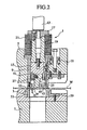
Fig. 2 is a cross sectional explanatory view of a bending process state; -
Figs. 3A and 3B are explanatory views showing a shape of a main portion of a punch chip; -
Fig. 4 is a plan explanatory view of a lower metal mold; -
Fig. 5 is a cross sectional explanatory view of a main portion showing a second embodiment of the upper metal mold; -
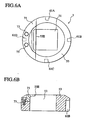
Fig. 6A is a plan view showing a second embodiment of the lower metal mold to be used with the upper mold according to the invention; -
Fig. 6B is a cross sectional side elevational view showing a second embodiment of said lower mold; and -
Figs. 7A and 7B are explanatory views schematically showing a manufacturing step of a product formed by the upper metal mold in accordance with the present invention. - A description will be in detail given below of embodiments of a processing method of a formed product in accordance with the present invention, and an upper metal mold and a lower metal mold used for the method.
- First, a description will be given in detail of a structure of an upper metal mold in accordance with the present invention with reference to
Fig. 1 . Referring toFig. 1 , a metal mold apparatus is constituted by an upper metal mold 1 and alower metal mold 3, the upper metal mold 1 is detachably loaded to anupper mold holder 5 of a punch press (not shown), and thelower metal mold 3 is detachably loaded to alower mold holder 7. - The upper and lower
metal mold holders - According to a preferred embodiment of the present invention. The upper metal mold 1 is provided with a
tubular punch guide 9 which is fitted into an upper mold loading hole formed in theupper mold holder 5 so as to be movable upward and downward. Thepunch guide 9 is supported by alifter spring 11 provided at a plurality of positions of theupper mold holder 5 so as to be movable upward and downward, and akey groove 9G in a vertical direction engaging with akey 13 fixed to theupper mold hold 5 is formed in an outer peripheral surface of thepunch guide 9. - A
punch body 15 is fitted into thepunch guide 9 so as to be movable upward and downward, and apunch driver 19 having apunch head 17 fixed to an upper end portion thereof is integrally fixed to an upper portion of thepunch body 15 by a bolt. Further, astrip spring 21 is elastically provided between thepunch head 17 and thepunch guide 9. - A
key groove 15G in a vertical direction is formed in thepunch body 15, and a key 23 fixed to thepunch guide 9 is engaged with thekey groove 15G. Further, apunch chip 25 for bending a bending piece A of a raw material C downward is attached to a lower surface of thepunch body 15 so as to be slightly movable in a horizontal direction (a horizontal direction inFig. 1 ). - A
bending process portion 29 for bending the bending piece A is provided in a lower end portion of a chipmain body 27 of thepunch chip 25, and thebending process portion 29 protrudes in a slightly moving direction of thepunch chip 25. Further, an approximately vertical sliding surface 31 (refer toFig. 3A ) is formed in a protruding direction of thebending process portion 29 of thepunch chip 25, that is, an opposite side to the protruding side, and aninclined surface 33 is formed in an upper portion of thesliding surface 31. Theinclined surface 33 is inclined so as to be apart from the protruding direction of thebending process portion 29 toward an upper side. - A
head portion 35 in which an upper surface is brought into contact with a lower surface of thepunch body 15 is formed in an upper portion of the chipmain body 27 in thepunch chip 25, and alocking portion 37 protruding in a direction orthogonal to the slightly moving direction of the chip main body 27 (a direction perpendicular to the paper surface inFig. 1 ) is formed in a lower portion of thehead portion 35. - The
head portion 35 of the chipmain body 27 is fitted into aguide hole 39H formed in aguide ring 39 fixed to the lower surface of thepunch body 15 so as to be slightly movable in a horizontal direction inFig. 1 , and an appropriateelastic member 41 such as a coil spring or the like is elastically provided between theguide ring 39 and thehead portion 35. Theelastic member 41 is exemplified as one example of a pressure energizing member for pressure energizing the chipmain body 27 in the opposite direction to the protruding side of thebending process portion 29. - Further, in order to prevent the
punch chip 25 from falling down, asupport member 43 slidably locking and supporting thelocking portion 37 formed in thehead portion 35 in thepunch chip 25 is integrally attached to a lower portion of theguide ring 39. - There is provided a pressure moving mechanism for pressure moving the
punch chip 25 to a protruding side of thebending process portion 29 against an energizing force of theelastic member 41. The pressure moving mechanism is in more detail structured by the following portions. First, aplate presser foot 45 is integrally attached to a lower end portion of thepunch guide 9, and a punchchip pressing member 49 is provided in an upper surface of theplate presser foot 45. Aslidable contact surface 47 slidable with the slidingsurface 31 and theinclined surface 33 of the chipmain body 27 is formed in a side surface of the punch chip pressing member 49 (a protruding side surface of the bending process portion 29). - On the other hand, a lower portion side of the
slidable contact surface 47 forms, as mentioned above, the approximately vertical surface slidable with the slidingsurface 31 of thepunch chip 25, as shown inFig. 3A . Further, an upper portion side of theslidable contact surface 47 forms an inclined surface slidable with theinclined surface 33 of thepunch chip 25, as shown inFig. 3B . - As an operation will be described in detail later, the
inclined surface 33 brings the upper portion side of theslidable contact surface 47 into slidable contact by the pressure moving mechanism, whereby thepunch chip 25 is pressed in a leftward direction inFig. 1 and is moved in the same direction. - On the other hand, the
lower metal mold 3 is constituted by a diemain body 53 forming a comparativelylarge die hole 51 capable of dropping down the formed product B.Bending process edges Fig. 4 ) for executing the bending process of the workpiece are formed at a plurality of positions in an inner peripheral edge of thedie hole 51. Thebending process edges 55A to 55D are formed as inclined surfaces which are slightly inclined taking a spring back of the workpiece into consideration. In other words, thedie hole 51 is formed as a taper shape entirely. - In more detail, the taper shape is formed so as to be expanded in accordance that the
processing edge 55 goes to a lower side. In other words, an upper corner portion of each of the bending process edges 55A to 55D is formed at a slightly acute angle, for example, at 89 degrees, so that the workpiece is bent at 89 degrees and becomes thereafter at 90 degrees due to the spring back mentioned above. -
Dimensions die hole 51 to the respective bending process edges 55A, 55B, 55C and 55D are made different so as to correspond to a change of thickness of the workpiece to be bent In other words, when executing the bending process of the workpiece in cooperation with thepunch chip 25 of the upper metal mold 1, the structure is made such that the clearance with respect to thebending process portion 29 of the chipmain body 27 changes in correspondence to the thickness of the workpiece. Further,key grooves 61A to 61D which are freely engaged with and disengaged from a key 59 provided in thelower mold holder 7 side are formed at positions corresponding to the respective bending process edges 55A to 55D in the outer peripheral surface of the diemain body 53. - In this case, each of the bending process edges 55A to 55D is exemplified as a flat surface, however, may be formed as a convex or concave curved surface in accordance with a forming aspect of the bending piece A mentioned above. Further, the
respective dimensions 57A to 57D may be different dimensions, or may be equal dimensions in adjacent or opposing dimensions. - In this case, in the structure mentioned above, when relatively moving and positioning the plate-like work with respect to the processing position of the punch press and forming the slits S1 and S2 along the outer shape of the raw material C in accordance with the nibbling process or the like together with applying the punching process of the punching hole H to the raw material C forming the formed product B, the slits S 1 and S2 are processed while leaving a micro joint connecting the workpiece W and the raw material C. In the case of processing the slits S1 and S2, the process is not limited to the nibbling process, and it is possible to process the slits S 1 and S2 in accordance with a pursuit process (slotting process) or a laser process. In the case that the punching hole H and the slits S1 and S2 are processed as mentioned above, the burr is generated in the lower surface at a time of processing.
- Thereafter, by relatively moving and positioning the workpiece W to the processing position by means of the upper metal mold 1 and the
lower metal mold 3, positioning a bending position E of the bending piece A in the raw material C with respect to the desiredbending process edge 55 which is previously set in correspondence to the thickness of the workpiece W in thelower metal mold 3, moving downward a ram (striker) 63 provided in the punch press so as to be movable upward and downward, and pressing and downward moving thepunch head 17 in the upper metal mold 1, an entire of the upper metal mold 1 is moved downward against a weak energizing force of thelifter spring 11. - As mentioned above, when the upper metal mold 1 is moved downward, and the
plate presser foot 45 provided in the lower end portion of thepunch guide 9 is brought into contact with the workpiece W on thelower metal mold 3, the downward movement of thepunch guide 9 is stopped, and thestripper ring 21 is gradually compressed. Accordingly, the workpiece W is firmly pressure fixed to thelower metal mold 3. - When further moving downward the
ram 63 in a state in which the workpiece W is pressure fixed to thelower metal mold 3 by theplate presser foot 45, thepunch body 15 is relatively moved downward with respect to thepunch guide 9, and the bending piece A of the raw material C is bent downward at the bending position E by thebending process portion 29 in thepunch chip 25 provided in the lower portion of thepunch body 15. - As mentioned above, since the
punch chip 25 is relatively moved downward with respect to thepunch guide 9 at a time of bending the bending piece A of the raw material C, the slidable contact surface of thepunch chip 25 with respect to theslidable contact surface 47 of the punchchip pressing member 49 is changed from the slidingsurface 31 to theinclined surface 33, so that thepunch chip 25 is slightly pressure moved to the protruding side of the bending process portion 29 (the left side inFig. 1 ) against the energizing force of theelastic member 41. - Accordingly, as mentioned above, the bending piece A of the raw material C is over-bent (bent, for example, over 90 degrees) while taking the spring back into consideration.
- Thereafter, when the
ram 63 is moved upward, the upper metal mold 1 is returned to the original position on the basis of an operation of thelifter spring 11, and is returned to the original state on the basis of the operations of thestripper spring 21 and theelastic member 41. - As has been already understood, the bending piece A of the raw material C is over-bent so as to be along the inclined surface of the
bending process edge 55. In other words, the bending piece A is bent in the downward direction over 90 degrees while taking the spring back into consideration. Accordingly, the bending angle (for example, 90 degrees) of the bending piece A forms an accurate bending angle. - When bending the bending piece A of the raw material C in the downward direction as mentioned above, the bending piece A is positioned within the
die hole 51, so that it is hard to largely move the workpiece in the X-axis and Y-axis directions in the next step. - Accordingly, the workpiece W is pressure fixed to the
lower metal mold 3 by positioning the micro joint D connecting the workpiece W and the raw material C at the position corresponding to thebending process edge 55 and thereafter moving downward theram 63 again. Thereafter, the micro joint D is cut and separated by thebending process portion 29 in thepunch chip 25, and the formed product B in a state in which the bending piece A is bent in the downward direction is dropped into thedie hole 51. - As is understood from the description mentioned above, since the burr at a time of processing the slits S 1 and S2 forming the raw material C and the burr at a time of processing the punching hole H are generated in the lower surface of the workpiece W, and the bending process of the bending piece A is thereafter executed in the downward direction, the generating side of the burr and the protruding side of the bending piece A are identical to each other. In other words, the protruding side of the bending piece A and the generating side of the burr can be set to the back surface of the formed product B, and it is possible to omit the deburring of the formed product B. Accordingly, it is possible to cancel the conventional problem as mentioned above.
- The present invention is not limited to the embodiment as mentioned above, and can be realized in accordance with the other aspects by employing an appropriate change within the scope of the appended claims. For example, the following structure can be employed as the pressure moving mechanism for moving the
punch chip 25 to the protruding side of thebending process portion 29 against the energizing force of theelastic member 41 at a time when thepunch chip 25 is relatively moved downward with respect to thepunch guide 9. - In other words, the structure may be made such that a
pressing block 65 freely pressing thepunch chip 25 is slidably provided, as shown inFig. 5 showing a second embodiment of the metal mold 1, on an upper surface of theplate presser foot 45 or a punchchip guide member 149, awedge block 67 allowed to be pressed down by the lower surface of thesupport member 43 is arranged between thepressing block 65 and the inner peripheral surface of thepunch guide 9 so as to be movable upward and downward, and anelastic member 69 such as a tension spring is provided in a tensional manner between thepressing block 65 and thewedge block 67, for the purpose of holding an inclined surface of thepressing block 65 and an inclined surface of thewedge block 67 in a full-time contact state. - In the case of the present embodiment, an approximately vertical sliding
surface 131 of thepunch chip 25 is formed longer upward than the slidingsurface 31 in accordance with the first embodiment mentioned above. Accordingly, even if thepunch chip 25 is moved downward to a lower end position, a side surface of the punchchip guide member 149 neither is in contact with the inclined surface 33 (refer toFig. 3B ) nor slide. - In accordance with the structure mentioned above, in the case that the
support member 43 fixed to the lower surface of thepunch body 15 is brought into contact with thewedge block 67 so as to gradually move downward thewedge block 67 at a time of the bending process of the bending piece A of the raw material C, thepressing block 65 is gradually moved in a leftward direction inFig. 5 , and pressure moves thepunch chip 25 in the leftward direction. - Therefore, in accordance with the structure mentioned above, when bending the bending piece A of the raw material C in the downward direction, it is possible to over-bend the bending piece A, and it is possible to achieve the same effect as mentioned above.
- Further, in the
lower metal mold 3, as shown inFigs. 6A and 6B showing a second embodiment of thelower metal mold 3, the structure may be made such that adie chip 71 provided with abending process edge 55E at a position corresponding to thedie hole 51 is attached to the diemain body 53 by a fixingdevice 73 such as a plurality of bolts or the like so as to be detachable and replaceable. - In accordance with the structure mentioned above, the
die chip 71 can be made of an expensive material, the diemain body 53 can be made of an inexpensive material, and a processing accuracy of thedie hole 51 may be rough, so that it is possible to inexpensively manufacture an entire structure. - Next, a description will be given of an embodiment of a processing method of a formed product in accordance with the present invention with reference to
Figs. 7A and 7B . - First, as shown in
Fig. 7A , in the case of forming the formed product B provided with the punching hole H at the appropriate position and provided with the bending piece A protruding in one direction by the punch press, the following processing method is employed. - In a first step, the micro joint D connecting the workpiece W and the raw material C is left at a time of moving and positions the workpiece W in the X-axis and Y-axis directions with respect to the processing position of the punch press, executing the punching process of the punching hole H as shown in
Fig. 7B , processing the slit S 1 in the portion forming the bending piece A in accordance with the nibbling process or the like, and processing the slit S2 along the outer shape of the raw material C forming the formed product B. In this case, an nibbling metal mold or the like is used in the nibbling process or the like which is independent from the metal mold in accordance with the present invention. - At this time, when executing the punching process of the punching hole H and processing the slits S 1 and S2 in accordance with the nibbling process or the like, the burr is generated in the lower surface of the workpiece W.
- Next, in a second step, the raw material C is formed at a plurality of positions of the workpiece W by positioning the workpiece W at the processing position and repeating the slit process, and the formed product B is thereafter processed by bending the bending piece A at the bending position E by the
metal molds 1 and 3 in accordance with the present invention. At this time, the bending piece A is bent in the downward direction, and the bending piece A enters into thedie hole 51 of thelower metal mold 3. - Further, in a third step, the micro joint D connecting the workpiece W and the raw material C is positioned at the position corresponding to the
bending process edge 55. In other words, the workpiece is moved in the rightward direction inFig. 1 by the workpiece positioning mechanism of the punch press so as to be changed from a state in which thebending process edge 55 matches to the bending process portion E, to a state in which the micro joint D matches to the bending process portion E. - When again moving downward the
ram 63 in the state in which the micro joint D matches to the bending process portion E, the workpiece W is pressure fixed to thelower metal mold 3. Thereafter, the micro joint D is cut and separated by thebending process portion 29 in thepunch chip 25, and the formed product B in the state in which the bending piece A is bent in the downward direction is dropped below thelower metal mold 3 while passing through the inner side of thedie hole 51. - Accordingly, the formed product having the bending piece A protruding to the lower side of the workpiece W is separated from the workpiece W, whereby it is possible to move the workpiece W in the X-axis and Y-axis directions without generating an interference between the bending piece A and the
lower metal mold 3. Therefore, it is possible to smoothly carry out the process of the next formed product in the workpiece W. - Further, since the generating direction of the burr and the bending direction of the bending piece protrude to the same direction (the back surface) of the workpiece, it is possible to omit the deburring applied to the separated formed product, so that it is possible to improve a productivity.
Claims (4)
- A processing method of processing a formed product by a punch press, comprising:(a) a step of leaving a micro joint (D) connecting a workpiece (W) to a raw material (C) for the formed product (B) at a time of forming a slit (S1,S2) in the workpiece (W) along an outer shape of the raw material (C);(b) a step of forming the formed product (B) by positioning a bending process portion of the raw material (C) on a lower metal mold (3) and bending the bending process portion downward on the basis of a cooperation of an upper metal mold (1) and the lower metal mold (3); and(c) a step of dropping the formed product (B) by separating the connection between the formed product (B) and the workpiece (W) by the micro joint (D).
- An upper metal mold (1), comprising:a punch guide (9) supported to an upper mold holder (5) in a punch press so as to be movable upward and downward;a punch body (15) provided within the punch guide (9) so as to be movable upward anddownward; anda punch chip (25) provided in a lower end portion of the punch body (15), characterized in that
a bending process portion is provided in a lower end portion of the punch chip (25) so as to protrude to a side portion; and in that
the punch chip (25) is provided so as to be movable by a pressure moving mechanism in a protruding direction of the bending process portion (29) with respect to the punch body (15) against an energizing force of an elastic member (41),said pressure moving mechanism is structured by a plate presser foot (45) integrally attached to a lower end portion of the punch guide (9) and a punch chip pressing member (49) is provided in an upper surface of the plate presser foot (45), wherein an inclined surface (33) is formed in an opposite side to the protruding direction of the bending process portion (29) in the punch chip (25), whereby the punch chip (25) is slidable with said inclined surface (33). - The upper metal mold (1) according to claim 2, wherein
the pressure moving mechanism pressure moves the punch chip (25) in the protruding
direction of the bending process portion at a time when the punch body (15) moves downward. - The upper metal mold (1) according to claim 3, wherein
and
a punch chip pressing member (49) of the pressure moving mechanism is provided in a lower portion of the punch guide (9), the pressing member (49) being slidable with the inclined surface (33).
Applications Claiming Priority (3)
| Application Number | Priority Date | Filing Date | Title |
|---|---|---|---|
| JP2002289207A JP4279532B2 (en) | 2002-10-01 | 2002-10-01 | Mold apparatus and lower mold for use in processing method of molded product |
| JP2002289207 | 2002-10-01 | ||
| PCT/JP2003/012507 WO2004030842A1 (en) | 2002-10-01 | 2003-09-30 | Method of processing formed product, and metal cope and metal drag used for the method |
Publications (3)
| Publication Number | Publication Date |
|---|---|
| EP1568421A1 EP1568421A1 (en) | 2005-08-31 |
| EP1568421A4 EP1568421A4 (en) | 2010-10-13 |
| EP1568421B1 true EP1568421B1 (en) | 2012-12-26 |
Family
ID=32063707
Family Applications (1)
| Application Number | Title | Priority Date | Filing Date |
|---|---|---|---|
| EP03748616A Expired - Lifetime EP1568421B1 (en) | 2002-10-01 | 2003-09-30 | Method of processing of a formed product and metal upper mold used for the method |
Country Status (8)
| Country | Link |
|---|---|
| US (1) | US7490501B2 (en) |
| EP (1) | EP1568421B1 (en) |
| JP (1) | JP4279532B2 (en) |
| KR (2) | KR100624652B1 (en) |
| CN (2) | CN102248082B (en) |
| AU (1) | AU2003268694A1 (en) |
| TW (1) | TWI235685B (en) |
| WO (1) | WO2004030842A1 (en) |
Families Citing this family (24)
| Publication number | Priority date | Publication date | Assignee | Title |
|---|---|---|---|---|
| JP4984395B2 (en) * | 2005-01-28 | 2012-07-25 | アイシン精機株式会社 | Press mold |
| JP5371177B2 (en) * | 2006-03-24 | 2013-12-18 | 株式会社アマダ | Bending die in punch press and processing method using the bending die |
| DE102006049044B4 (en) * | 2006-10-18 | 2018-01-11 | Trumpf Werkzeugmaschinen Gmbh + Co. Kg | Tool for cutting plate-like workpieces |
| PL2177289T3 (en) * | 2008-10-20 | 2011-12-30 | Trumpf Werkzeugmaschinen Gmbh Co Kg | Machine tools and method for discharging a workpiece part |
| WO2011042058A1 (en) * | 2009-10-08 | 2011-04-14 | Tomologic Ab | Controlling rules and variables for cutting |
| KR101281051B1 (en) * | 2010-06-25 | 2013-07-01 | 삼성중공업 주식회사 | structure for prevent flexural deformation and constructing method of reinforcement for prevent flexural deformation of hole surroundings on the ship construction |
| TWI386259B (en) * | 2010-09-29 | 2013-02-21 | Nat Kaohsiung First University Of Science Technology | With the mold material within the heating function of the stamping die |
| BR112013025570B1 (en) * | 2011-04-07 | 2018-05-22 | Tomologic Ab | METHOD AND SYSTEM FOR CUTTING MACHINE VARIOUS PARTS OF A PIECE OF MATERIAL |
| CN102284614A (en) * | 2011-06-16 | 2011-12-21 | 吴江市华源印铁制罐有限责任公司 | Prebending and punching combined mold and process thereof |
| CN102310143B (en) * | 2011-09-28 | 2013-06-12 | 苏州三维精密机械有限公司 | Machining process for rim charge settlement slot |
| JP6001845B2 (en) | 2011-11-30 | 2016-10-05 | 株式会社アマダホールディングス | Product storage method, product storage device, processing system, and method of manufacturing stored product |
| DE102012206657A1 (en) * | 2012-04-23 | 2013-03-21 | Trumpf Werkzeugmaschinen Gmbh + Co. Kg | Method for introducing a deformation into a plate-like workpiece |
| CN102744559A (en) * | 2012-07-12 | 2012-10-24 | 内蒙古第一机械集团有限公司 | Method for quickly and precisely positioning bending of steel plate |
| CN104812508B (en) * | 2012-11-30 | 2016-11-09 | 丰田自动车株式会社 | Shearing device and cutting-off method |
| CN104741445B (en) * | 2013-12-26 | 2016-12-07 | 襄阳三金模具有限公司 | A kind of manufacture processing method of Triangular Arm |
| CN109843465B (en) * | 2016-09-26 | 2020-12-18 | 通快机床两合公司 | Method, machine tool and grooving tool for multi-stroke progressive grooving of plate-shaped workpieces |
| EP3515625A1 (en) * | 2016-09-26 | 2019-07-31 | Trumpf Werkzeugmaschinen GmbH + Co. KG | Tool and machine tool and method for machining plate-like workpieces |
| CN109789471B (en) * | 2016-09-26 | 2022-02-11 | 通快机床两合公司 | Tool and machine tool for cutting and/or shaping plate-shaped workpieces and method |
| WO2019146246A1 (en) * | 2018-01-26 | 2019-08-01 | パナソニックIpマネジメント株式会社 | Bus bar and power source device |
| CN108246883A (en) * | 2018-02-12 | 2018-07-06 | 珠海格力精密模具有限公司 | Punch fixed structure and with its punch-head assembly |
| TWI674159B (en) * | 2018-02-14 | 2019-10-11 | 革蘭科技有限公司 | Multi-row pipe fitting punching structure |
| JP7149085B2 (en) * | 2018-03-20 | 2022-10-06 | 株式会社アマダ | Hole punching method and mold |
| IT202000020440A1 (en) * | 2020-08-26 | 2022-02-26 | Mas Mecc S R L | METHOD AND EQUIPMENT FOR MAKING OBJECTS IN FOLDED SHEET METAL |
| CN113523091B (en) * | 2021-06-23 | 2022-07-19 | 东风柳州汽车有限公司 | 7-shaped hole machining method |
Family Cites Families (38)
| Publication number | Priority date | Publication date | Assignee | Title |
|---|---|---|---|---|
| US4266310A (en) * | 1977-10-17 | 1981-05-12 | Frederick Perrault | Arrangement for forming metal parts |
| JPS61289920A (en) * | 1985-06-14 | 1986-12-19 | Nissan Motor Co Ltd | Hem forming method |
| JPS6264424A (en) * | 1985-09-13 | 1987-03-23 | Mitsubishi Electric Corp | U-bending device |
| JPS6487018A (en) * | 1987-09-30 | 1989-03-31 | Anritsu Corp | Working method for sheet metal |
| JPH0391123A (en) | 1989-09-01 | 1991-04-16 | Hitachi Ltd | Optical head device and semiconductor laser device used in the same |
| JPH0588714A (en) | 1991-09-25 | 1993-04-09 | Hitachi Ltd | Method and device for estimation of energy demand in wide range |
| JP2515611Y2 (en) * | 1992-04-28 | 1996-10-30 | 株式会社アマダメトレックス | Variable step bending die for automatic replacement |
| JP2545176B2 (en) * | 1992-05-19 | 1996-10-16 | 株式会社アマダメトレックス | Mold for punching machine |
| JP2611089B2 (en) | 1992-06-30 | 1997-05-21 | 株式会社アマダメトレックス | Mold for molding |
| US5303539A (en) * | 1993-01-29 | 1994-04-19 | The Gillette Company | Staple forming |
| JP3391838B2 (en) * | 1993-03-29 | 2003-03-31 | キヤノン精機株式会社 | Method for manufacturing comb teeth of stator of stepping motor |
| JPH0732066A (en) * | 1993-07-19 | 1995-02-03 | Amada Co Ltd | Turret punch press |
| JPH07164058A (en) | 1993-12-15 | 1995-06-27 | Murata Mach Ltd | Sheet bending machine and method for using it |
| JPH07204747A (en) * | 1994-01-24 | 1995-08-08 | Sony Corp | Pressing die for bending |
| IT1278356B1 (en) | 1995-02-06 | 1997-11-20 | Sapim Amada Spa | FOLDING EQUIPMENT FOR SHEETS. |
| US5640873A (en) * | 1995-05-15 | 1997-06-24 | Costabile; Arvid Bennett | Punch and die assembly |
| JP3653793B2 (en) * | 1995-05-31 | 2005-06-02 | 日産自動車株式会社 | Press working mold and press working method |
| KR100245267B1 (en) * | 1996-06-03 | 2000-02-15 | 모리 하루오 | Car navigation system |
| US5910177A (en) * | 1996-12-09 | 1999-06-08 | Visteon Technologies, Llc | Navigating close proximity routes with a vehicle navigation system |
| US5741105A (en) * | 1997-01-31 | 1998-04-21 | Dayton Systems Group, Inc. | Method of and apparatus for manufacturing tabs for easy-open can end |
| CN1095706C (en) * | 1997-02-14 | 2002-12-11 | 好丽友金属工业株式会社 | Method of manufcturing frame of cathod ray tube |
| IT1292330B1 (en) | 1997-05-27 | 1999-01-29 | Crea Srl | PROCEDURE FOR THE PRODUCTION OF FOLDED SHEET METAL PIECES |
| CN1229702A (en) * | 1998-03-20 | 1999-09-29 | 机械工业部济南铸造锻压机械研究所 | Punching folding combined shaper for metal thin plate |
| JP3916327B2 (en) | 1998-07-08 | 2007-05-16 | 株式会社アマダ | Bending mold set and punch press |
| JP2000084630A (en) * | 1998-09-11 | 2000-03-28 | Iwatsu Electric Co Ltd | Machining method for platelike fitting parts |
| JP2000153321A (en) * | 1998-11-18 | 2000-06-06 | Toyota Motor Corp | Method and die for punch-out and bend forming |
| US6292743B1 (en) * | 1999-01-06 | 2001-09-18 | Infogation Corporation | Mobile navigation system |
| US6285950B1 (en) * | 1999-05-13 | 2001-09-04 | Alpine Electronics, Inc. | Vehicle navigation system |
| US6065324A (en) * | 1999-07-01 | 2000-05-23 | Power Brake Dies, Inc. | Rotary bender die |
| US6122593A (en) * | 1999-08-03 | 2000-09-19 | Navigation Technologies Corporation | Method and system for providing a preview of a route calculated with a navigation system |
| JP2001277058A (en) * | 2000-03-28 | 2001-10-09 | Amada Co Ltd | Compound plate working method including laser beam machining and pressing |
| DE10019407A1 (en) * | 2000-04-19 | 2001-10-25 | Bosch Gmbh Robert | Navigation system has sensors that detect faults or driver deterioration and plan emergency rerouting to e.g. car park |
| CN1247340C (en) * | 2000-09-21 | 2006-03-29 | 吕亚舜 | Double-function hydraulic gearing bender for sheet material |
| US6424910B1 (en) * | 2000-11-22 | 2002-07-23 | Navigation Technologies Corp. | Method and system for providing related navigation features for two or more end users |
| US6427119B1 (en) * | 2001-04-16 | 2002-07-30 | General Motors Corporation | Method and system for providing multiple entry points to a vehicle navigation route |
| US6725156B2 (en) * | 2001-05-10 | 2004-04-20 | Navigation Technologies Corp. | Method and system for providing backup driving instructions with a navigation system |
| US6424912B1 (en) * | 2001-11-09 | 2002-07-23 | General Motors Corporation | Method for providing vehicle navigation instructions |
| US6691547B2 (en) * | 2001-12-21 | 2004-02-17 | E & E Manufacturing Company, Inc. | Method of doing business and manufacturing in a stamping and extrusion facility |
-
2002
- 2002-10-01 JP JP2002289207A patent/JP4279532B2/en not_active Expired - Fee Related
-
2003
- 2003-09-30 KR KR1020057005721A patent/KR100624652B1/en not_active IP Right Cessation
- 2003-09-30 US US10/529,789 patent/US7490501B2/en not_active Expired - Fee Related
- 2003-09-30 AU AU2003268694A patent/AU2003268694A1/en not_active Abandoned
- 2003-09-30 EP EP03748616A patent/EP1568421B1/en not_active Expired - Lifetime
- 2003-09-30 KR KR1020067014103A patent/KR100624654B1/en not_active IP Right Cessation
- 2003-09-30 CN CN201110175631.3A patent/CN102248082B/en not_active Expired - Fee Related
- 2003-09-30 WO PCT/JP2003/012507 patent/WO2004030842A1/en active Application Filing
- 2003-09-30 CN CN038233339A patent/CN1684779B/en not_active Expired - Fee Related
- 2003-10-01 TW TW092127145A patent/TWI235685B/en not_active IP Right Cessation
Also Published As
| Publication number | Publication date |
|---|---|
| CN1684779B (en) | 2012-12-12 |
| KR100624654B1 (en) | 2006-09-15 |
| EP1568421A4 (en) | 2010-10-13 |
| US7490501B2 (en) | 2009-02-17 |
| CN102248082B (en) | 2015-02-04 |
| AU2003268694A1 (en) | 2004-04-23 |
| WO2004030842A1 (en) | 2004-04-15 |
| KR20050049515A (en) | 2005-05-25 |
| TWI235685B (en) | 2005-07-11 |
| KR100624652B1 (en) | 2006-09-15 |
| CN102248082A (en) | 2011-11-23 |
| US20060027626A1 (en) | 2006-02-09 |
| JP4279532B2 (en) | 2009-06-17 |
| CN1684779A (en) | 2005-10-19 |
| JP2004122169A (en) | 2004-04-22 |
| TW200408468A (en) | 2004-06-01 |
| EP1568421A1 (en) | 2005-08-31 |
| KR20060088571A (en) | 2006-08-04 |
Similar Documents
| Publication | Publication Date | Title |
|---|---|---|
| EP1568421B1 (en) | Method of processing of a formed product and metal upper mold used for the method | |
| EP2305395B1 (en) | Press working equipment and press working method | |
| JP3415358B2 (en) | Composite mold and composite molding method | |
| JPH079045A (en) | Pressing device | |
| EP1949984A1 (en) | Method of manufacturing ring-shaped member | |
| JP5371177B2 (en) | Bending die in punch press and processing method using the bending die | |
| JP4873601B2 (en) | Mold for punch press | |
| JP3489378B2 (en) | Press equipment | |
| JP2006247675A (en) | Punch for press working and press working method | |
| JP6159108B2 (en) | Bending mold | |
| JP2007125591A (en) | Folding method by punch press and punch press | |
| JP4292617B2 (en) | Press machine | |
| JP2020127959A (en) | Sheet metal part, manufacturing method of sheet metal part and progressive die | |
| JP3046634B2 (en) | Precision punching die equipment | |
| JP4867502B2 (en) | Press machine | |
| JP4794060B2 (en) | Punch mold | |
| JP5007110B2 (en) | Mold | |
| CN214977125U (en) | Forming and punching composite die | |
| JP6594483B1 (en) | Corner part forming die, method for manufacturing the same and corner part forming method | |
| WO2018173997A1 (en) | Die mold for assymetrical bending, mold set for assymetrical bending, and bending processing method | |
| JPH0719617Y2 (en) | Press type cam device | |
| JP2005349421A (en) | Die set | |
| JP3117089U (en) | Die set for drilling pipe cylindrical surface, drilling mechanism and drilling press | |
| JP4207319B2 (en) | Groove forming method for metal plate | |
| JP2021074757A (en) | Method of manufacturing member having groove and groove processing device |
Legal Events
| Date | Code | Title | Description |
|---|---|---|---|
| PUAI | Public reference made under article 153(3) epc to a published international application that has entered the european phase |
Free format text: ORIGINAL CODE: 0009012 |
|
| 17P | Request for examination filed |
Effective date: 20050419 |
|
| AK | Designated contracting states |
Kind code of ref document: A1 Designated state(s): AT BE BG CH CY CZ DE DK EE ES FI FR GB GR HU IE IT LI LU MC NL PT RO SE SI SK TR |
|
| AX | Request for extension of the european patent |
Extension state: AL LT LV MK |
|
| DAX | Request for extension of the european patent (deleted) | ||
| A4 | Supplementary search report drawn up and despatched |
Effective date: 20100915 |
|
| RIC1 | Information provided on ipc code assigned before grant |
Ipc: B21D 5/01 20060101AFI20040420BHEP Ipc: B21D 28/36 20060101ALI20100909BHEP Ipc: B21D 5/04 20060101ALI20100909BHEP Ipc: B21D 28/10 20060101ALI20100909BHEP |
|
| 17Q | First examination report despatched |
Effective date: 20110324 |
|
| GRAP | Despatch of communication of intention to grant a patent |
Free format text: ORIGINAL CODE: EPIDOSNIGR1 |
|
| GRAS | Grant fee paid |
Free format text: ORIGINAL CODE: EPIDOSNIGR3 |
|
| GRAA | (expected) grant |
Free format text: ORIGINAL CODE: 0009210 |
|
| AK | Designated contracting states |
Kind code of ref document: B1 Designated state(s): AT BE BG CH CY CZ DE DK EE ES FI FR GB GR HU IE IT LI LU MC NL PT RO SE SI SK TR |
|
| REG | Reference to a national code |
Ref country code: GB Ref legal event code: FG4D |
|
| REG | Reference to a national code |
Ref country code: CH Ref legal event code: EP |
|
| REG | Reference to a national code |
Ref country code: AT Ref legal event code: REF Ref document number: 590166 Country of ref document: AT Kind code of ref document: T Effective date: 20130115 |
|
| REG | Reference to a national code |
Ref country code: DE Ref legal event code: R096 Ref document number: 60342954 Country of ref document: DE Effective date: 20130307 |
|
| PG25 | Lapsed in a contracting state [announced via postgrant information from national office to epo] |
Ref country code: FI Free format text: LAPSE BECAUSE OF FAILURE TO SUBMIT A TRANSLATION OF THE DESCRIPTION OR TO PAY THE FEE WITHIN THE PRESCRIBED TIME-LIMIT Effective date: 20121226 Ref country code: SE Free format text: LAPSE BECAUSE OF FAILURE TO SUBMIT A TRANSLATION OF THE DESCRIPTION OR TO PAY THE FEE WITHIN THE PRESCRIBED TIME-LIMIT Effective date: 20121226 |
|
| REG | Reference to a national code |
Ref country code: AT Ref legal event code: MK05 Ref document number: 590166 Country of ref document: AT Kind code of ref document: T Effective date: 20121226 |
|
| REG | Reference to a national code |
Ref country code: NL Ref legal event code: VDEP Effective date: 20121226 |
|
| PG25 | Lapsed in a contracting state [announced via postgrant information from national office to epo] |
Ref country code: SI Free format text: LAPSE BECAUSE OF FAILURE TO SUBMIT A TRANSLATION OF THE DESCRIPTION OR TO PAY THE FEE WITHIN THE PRESCRIBED TIME-LIMIT Effective date: 20121226 Ref country code: GR Free format text: LAPSE BECAUSE OF FAILURE TO SUBMIT A TRANSLATION OF THE DESCRIPTION OR TO PAY THE FEE WITHIN THE PRESCRIBED TIME-LIMIT Effective date: 20130327 |
|
| PG25 | Lapsed in a contracting state [announced via postgrant information from national office to epo] |
Ref country code: BE Free format text: LAPSE BECAUSE OF FAILURE TO SUBMIT A TRANSLATION OF THE DESCRIPTION OR TO PAY THE FEE WITHIN THE PRESCRIBED TIME-LIMIT Effective date: 20121226 Ref country code: AT Free format text: LAPSE BECAUSE OF FAILURE TO SUBMIT A TRANSLATION OF THE DESCRIPTION OR TO PAY THE FEE WITHIN THE PRESCRIBED TIME-LIMIT Effective date: 20121226 Ref country code: CZ Free format text: LAPSE BECAUSE OF FAILURE TO SUBMIT A TRANSLATION OF THE DESCRIPTION OR TO PAY THE FEE WITHIN THE PRESCRIBED TIME-LIMIT Effective date: 20121226 Ref country code: CY Free format text: LAPSE BECAUSE OF FAILURE TO SUBMIT A TRANSLATION OF THE DESCRIPTION OR TO PAY THE FEE WITHIN THE PRESCRIBED TIME-LIMIT Effective date: 20121226 Ref country code: BG Free format text: LAPSE BECAUSE OF FAILURE TO SUBMIT A TRANSLATION OF THE DESCRIPTION OR TO PAY THE FEE WITHIN THE PRESCRIBED TIME-LIMIT Effective date: 20130326 Ref country code: EE Free format text: LAPSE BECAUSE OF FAILURE TO SUBMIT A TRANSLATION OF THE DESCRIPTION OR TO PAY THE FEE WITHIN THE PRESCRIBED TIME-LIMIT Effective date: 20121226 Ref country code: SK Free format text: LAPSE BECAUSE OF FAILURE TO SUBMIT A TRANSLATION OF THE DESCRIPTION OR TO PAY THE FEE WITHIN THE PRESCRIBED TIME-LIMIT Effective date: 20121226 Ref country code: ES Free format text: LAPSE BECAUSE OF FAILURE TO SUBMIT A TRANSLATION OF THE DESCRIPTION OR TO PAY THE FEE WITHIN THE PRESCRIBED TIME-LIMIT Effective date: 20130406 |
|
| PG25 | Lapsed in a contracting state [announced via postgrant information from national office to epo] |
Ref country code: NL Free format text: LAPSE BECAUSE OF FAILURE TO SUBMIT A TRANSLATION OF THE DESCRIPTION OR TO PAY THE FEE WITHIN THE PRESCRIBED TIME-LIMIT Effective date: 20121226 Ref country code: PT Free format text: LAPSE BECAUSE OF FAILURE TO SUBMIT A TRANSLATION OF THE DESCRIPTION OR TO PAY THE FEE WITHIN THE PRESCRIBED TIME-LIMIT Effective date: 20130426 Ref country code: RO Free format text: LAPSE BECAUSE OF FAILURE TO SUBMIT A TRANSLATION OF THE DESCRIPTION OR TO PAY THE FEE WITHIN THE PRESCRIBED TIME-LIMIT Effective date: 20121226 |
|
| PG25 | Lapsed in a contracting state [announced via postgrant information from national office to epo] |
Ref country code: DK Free format text: LAPSE BECAUSE OF FAILURE TO SUBMIT A TRANSLATION OF THE DESCRIPTION OR TO PAY THE FEE WITHIN THE PRESCRIBED TIME-LIMIT Effective date: 20121226 |
|
| PLBE | No opposition filed within time limit |
Free format text: ORIGINAL CODE: 0009261 |
|
| STAA | Information on the status of an ep patent application or granted ep patent |
Free format text: STATUS: NO OPPOSITION FILED WITHIN TIME LIMIT |
|
| 26N | No opposition filed |
Effective date: 20130927 |
|
| PG25 | Lapsed in a contracting state [announced via postgrant information from national office to epo] |
Ref country code: IT Free format text: LAPSE BECAUSE OF FAILURE TO SUBMIT A TRANSLATION OF THE DESCRIPTION OR TO PAY THE FEE WITHIN THE PRESCRIBED TIME-LIMIT Effective date: 20121226 |
|
| REG | Reference to a national code |
Ref country code: DE Ref legal event code: R097 Ref document number: 60342954 Country of ref document: DE Effective date: 20130927 |
|
| PG25 | Lapsed in a contracting state [announced via postgrant information from national office to epo] |
Ref country code: MC Free format text: LAPSE BECAUSE OF FAILURE TO SUBMIT A TRANSLATION OF THE DESCRIPTION OR TO PAY THE FEE WITHIN THE PRESCRIBED TIME-LIMIT Effective date: 20121226 |
|
| REG | Reference to a national code |
Ref country code: CH Ref legal event code: PL |
|
| GBPC | Gb: european patent ceased through non-payment of renewal fee |
Effective date: 20130930 |
|
| REG | Reference to a national code |
Ref country code: FR Ref legal event code: ST Effective date: 20140530 |
|
| REG | Reference to a national code |
Ref country code: IE Ref legal event code: MM4A |
|
| PG25 | Lapsed in a contracting state [announced via postgrant information from national office to epo] |
Ref country code: IE Free format text: LAPSE BECAUSE OF NON-PAYMENT OF DUE FEES Effective date: 20130930 Ref country code: CH Free format text: LAPSE BECAUSE OF NON-PAYMENT OF DUE FEES Effective date: 20130930 Ref country code: GB Free format text: LAPSE BECAUSE OF NON-PAYMENT OF DUE FEES Effective date: 20130930 Ref country code: LI Free format text: LAPSE BECAUSE OF NON-PAYMENT OF DUE FEES Effective date: 20130930 |
|
| PG25 | Lapsed in a contracting state [announced via postgrant information from national office to epo] |
Ref country code: FR Free format text: LAPSE BECAUSE OF NON-PAYMENT OF DUE FEES Effective date: 20130930 |
|
| PG25 | Lapsed in a contracting state [announced via postgrant information from national office to epo] |
Ref country code: TR Free format text: LAPSE BECAUSE OF FAILURE TO SUBMIT A TRANSLATION OF THE DESCRIPTION OR TO PAY THE FEE WITHIN THE PRESCRIBED TIME-LIMIT Effective date: 20121226 |
|
| PG25 | Lapsed in a contracting state [announced via postgrant information from national office to epo] |
Ref country code: HU Free format text: LAPSE BECAUSE OF FAILURE TO SUBMIT A TRANSLATION OF THE DESCRIPTION OR TO PAY THE FEE WITHIN THE PRESCRIBED TIME-LIMIT; INVALID AB INITIO Effective date: 20030930 Ref country code: LU Free format text: LAPSE BECAUSE OF NON-PAYMENT OF DUE FEES Effective date: 20130930 |
|
| PGFP | Annual fee paid to national office [announced via postgrant information from national office to epo] |
Ref country code: DE Payment date: 20190918 Year of fee payment: 17 |
|
| REG | Reference to a national code |
Ref country code: DE Ref legal event code: R119 Ref document number: 60342954 Country of ref document: DE |
|
| PG25 | Lapsed in a contracting state [announced via postgrant information from national office to epo] |
Ref country code: DE Free format text: LAPSE BECAUSE OF NON-PAYMENT OF DUE FEES Effective date: 20210401 |