EP1567798B1 - Dispositif permettant d'acheminer un milieu liquide et/ou gazeux a un systeme rotatif sous pression - Google Patents
Dispositif permettant d'acheminer un milieu liquide et/ou gazeux a un systeme rotatif sous pression Download PDFInfo
- Publication number
- EP1567798B1 EP1567798B1 EP03788856A EP03788856A EP1567798B1 EP 1567798 B1 EP1567798 B1 EP 1567798B1 EP 03788856 A EP03788856 A EP 03788856A EP 03788856 A EP03788856 A EP 03788856A EP 1567798 B1 EP1567798 B1 EP 1567798B1
- Authority
- EP
- European Patent Office
- Prior art keywords
- seal
- rotor
- stator
- coupling
- ring
- Prior art date
- Legal status (The legal status is an assumption and is not a legal conclusion. Google has not performed a legal analysis and makes no representation as to the accuracy of the status listed.)
- Expired - Lifetime
Links
- 239000007788 liquid Substances 0.000 title claims description 4
- 230000008878 coupling Effects 0.000 claims abstract description 54
- 238000010168 coupling process Methods 0.000 claims abstract description 54
- 238000005859 coupling reaction Methods 0.000 claims abstract description 54
- 238000007789 sealing Methods 0.000 claims description 27
- 239000000463 material Substances 0.000 claims description 12
- 230000001419 dependent effect Effects 0.000 claims description 6
- 230000005855 radiation Effects 0.000 claims description 5
- 230000000694 effects Effects 0.000 claims description 4
- 239000011248 coating agent Substances 0.000 claims description 3
- 238000000576 coating method Methods 0.000 claims description 3
- 230000000903 blocking effect Effects 0.000 claims 1
- 238000006073 displacement reaction Methods 0.000 claims 1
- 230000002093 peripheral effect Effects 0.000 claims 1
- 230000006903 response to temperature Effects 0.000 abstract 2
- 230000008859 change Effects 0.000 description 7
- 239000002184 metal Substances 0.000 description 6
- 230000009467 reduction Effects 0.000 description 5
- 230000007246 mechanism Effects 0.000 description 4
- 230000002349 favourable effect Effects 0.000 description 3
- 238000010438 heat treatment Methods 0.000 description 3
- 238000000926 separation method Methods 0.000 description 3
- 230000009471 action Effects 0.000 description 2
- 230000004888 barrier function Effects 0.000 description 2
- 230000008901 benefit Effects 0.000 description 2
- 238000004891 communication Methods 0.000 description 2
- 239000002245 particle Substances 0.000 description 2
- OKTJSMMVPCPJKN-UHFFFAOYSA-N Carbon Chemical compound [C] OKTJSMMVPCPJKN-UHFFFAOYSA-N 0.000 description 1
- 238000010521 absorption reaction Methods 0.000 description 1
- 238000001816 cooling Methods 0.000 description 1
- 230000003247 decreasing effect Effects 0.000 description 1
- 238000001514 detection method Methods 0.000 description 1
- 238000005516 engineering process Methods 0.000 description 1
- 239000012530 fluid Substances 0.000 description 1
- 229910002804 graphite Inorganic materials 0.000 description 1
- 239000010439 graphite Substances 0.000 description 1
- 230000001050 lubricating effect Effects 0.000 description 1
- 238000005461 lubrication Methods 0.000 description 1
- 238000003754 machining Methods 0.000 description 1
- 230000035515 penetration Effects 0.000 description 1
- 238000007639 printing Methods 0.000 description 1
- 230000001737 promoting effect Effects 0.000 description 1
- 230000001105 regulatory effect Effects 0.000 description 1
- 238000005096 rolling process Methods 0.000 description 1
- 230000035945 sensitivity Effects 0.000 description 1
Images


Classifications
-
- F—MECHANICAL ENGINEERING; LIGHTING; HEATING; WEAPONS; BLASTING
- F16—ENGINEERING ELEMENTS AND UNITS; GENERAL MEASURES FOR PRODUCING AND MAINTAINING EFFECTIVE FUNCTIONING OF MACHINES OR INSTALLATIONS; THERMAL INSULATION IN GENERAL
- F16L—PIPES; JOINTS OR FITTINGS FOR PIPES; SUPPORTS FOR PIPES, CABLES OR PROTECTIVE TUBING; MEANS FOR THERMAL INSULATION IN GENERAL
- F16L27/00—Adjustable joints; Joints allowing movement
- F16L27/08—Adjustable joints; Joints allowing movement allowing adjustment or movement only about the axis of one pipe
- F16L27/0804—Adjustable joints; Joints allowing movement allowing adjustment or movement only about the axis of one pipe the fluid passing axially from one joint element to another
- F16L27/0808—Adjustable joints; Joints allowing movement allowing adjustment or movement only about the axis of one pipe the fluid passing axially from one joint element to another the joint elements extending coaxially for some distance from their point of separation
- F16L27/0824—Adjustable joints; Joints allowing movement allowing adjustment or movement only about the axis of one pipe the fluid passing axially from one joint element to another the joint elements extending coaxially for some distance from their point of separation with ball or roller bearings
- F16L27/0828—Adjustable joints; Joints allowing movement allowing adjustment or movement only about the axis of one pipe the fluid passing axially from one joint element to another the joint elements extending coaxially for some distance from their point of separation with ball or roller bearings having radial bearings
Definitions
- the invention relates to a device for supplying a gaseous and / or liquid medium to a rotating pressure system, consisting of a stationary sealing head housing with a connection opening for the medium, followed by a running inside the sealing head housing connecting line, as well as with a likewise in the interior of the sealing head housing arranged with the pressure system in communication standing tubular rotor, further comprising a arranged at the end of the connecting line stator seal and arranged at the end of the rotor rotor seal, wherein the stator seal and the rotor seal are arranged coaxially to the rotor and abut against each other, and wherein in the Stator and rotor seal on thermally influenced expansion element, which makes a temperature-dependent adjustment of the mutual position and / or load of stator and rotor seal, characterized in that the expansion element is formed by a sleeve member which is fixed at its end facing the pressure system towards the seal head housing and with its end facing the stator seal rests against a standing at an elevated temperature with
- Devices of this type are used, for example, in the form of sealing heads or rotary feedthroughs of the fluid transfer from stationary to rotating machine components and / or vice versa. Due to the technical advancement, the requirements for rotary unions are steadily increasing. Especially in machine tools, the spindle speeds have within a decade of usually 4,000 to 6,000 rpm. at 20,000 to 50,000 rpm. elevated. In addition, the pressures of the media are constantly growing. Minimal lubrication and new applications, e.g. the blow-off of machining residues in the graphite chip by means of compressed air by feeding the medium into the tool are made extreme demands, especially on the seals of the rotary unions.
- the invention has for its object to provide a device of the type mentioned in the form of a rotary feedthrough, which achieves a long service life in a variety of applications and this has an intrinsic safety, so that regardless of the operating condition, medium and external conditions safe operation and a long life are guaranteed. Decisive for this is a reduction in the sealing and bearing load with the lowest possible leakage current.
- a thermally-influenced expansion element is arranged, which is formed by a sleeve part, which is fixed at its end facing the pressure system towards the seal head housing and facing with his the stator seal End rests against a at elevated temperature with the stator seal in connection with the coupling ring.
- the advantage achieved by the invention consists essentially in the fact that very short control times are achieved. On the one hand, a very sensitive control over the change in length is achieved. On the other hand, the large force resulting from the change in length has a predominant influence on the control behavior, regardless of the media pressure. Another advantage is the almost unlimited and wear-free repeatability of thermally induced Connectn Sungsvorgarigs.
- the expansion element can be provided at least on its inner circumferential surface with a heat radiation absorbing surface coating.
- a further advantageous embodiment of the invention is that the coupling ring encloses a stator seal bearing, axially displaceably mounted seal carrier which presses the stator seal against the axially fixed rotor seal under the force of a stator.
- the seal carrier has a radially to the coupling ring projecting annular collar.
- the coupling ring consists of a material of low thermal expansion coefficient and the seal carrier of a material of contrast, large thermal expansion coefficient, wherein at regular operating temperature between the coupling ring and the seal carrier a narrow annular gap is present , This ensures that the stator seal is applied during normal operation under the pressure of the stator of the rotor seal. Only with an intervention of the scheme required temperature rise occurs between the coupling ring and the seal carrier a frictional engagement, which then the expansion element on the coupling ring and the seal carrier can act on the stator seal in the sense that a discharge of the sealing surface occurs, but without a gap arises because of the penetration of particles and the resulting wear is undesirable.
- the outer diameter of the sealing head housing mounted part of the seal carrier diameter corresponds to the rotor receiving rotor bore and the bore diameter of the rotor seal and the stator seal are the same size. As a result, these axially attacking forces cancel each other.
- the rotor seal does not run after the stator seal has been retracted due to the control, the rotor seal is axially secured by means of a collar and positioned against this fuse by means of a spring element.
- a sealing gap is arranged with an annular channel before the first and after the last of the camp, in which a barrier medium with overpressure, eg compressed air is introduced and at least partially has connection to the leakage connection.
- a barrier medium with overpressure eg compressed air
- a further advantageous embodiment of the invention is characterized in that between the expansion element and the movably mounted seal carrier with respect to their length rotatably adjustable, thermally actuated coupling is arranged.
- the coupling of two rotatably mutually adjustable clutch plates is formed, of which at least one is designed as a wedge disk with one or more peripherally extending wedge surfaces.
- the clutch discs can be rotationally adjusted by means of an end connected to each of the clutch discs, spiral bi-metal element.
- the clutch discs are positioned against each other so that there is a lowest possible axial height of the two clutch discs. While a clutch disc rests on the expander and is rotatable, the second clutch disc is in contact with the first.
- the bi-metal element which is also connected to the second clutch disc, has rotated it into a position in which results in a minimum length of the clutch and there is no contact of the second clutch disc with the axially movable seal or the corresponding seal carrier.
- the second clutch disc is rotated so far on the wedge surfaces until contact with the axially movable seal or the corresponding seal carrier exists. Due to a small wedge angle in the area of self-locking, no further change in position occurs in the direction of rotation even at high axial load.
- the length expansion of the thermal expansion element now has a direct effect on the position or force reduction of the seal.
- a relief ring is arranged between the coupling ring and seal carrier.
- the coupling ring expediently consists of a material of low coefficient of thermal expansion and the relief ring of a material of the other hand, a large thermal expansion coefficient, wherein at regular operating temperature between the coupling ring and the relief ring, a narrow annular gap is present.
- the relief ring permanently applied by means of springs on the front side of the seal carrier on a specially shaped annular collar and is transmitted by metallic contact and thermal radiation, the temperature level of the seal carrier on the discharge ring.
- the relief ring is permanently pressed against the seal carrier.
- the temperature-dependent load control between the stator and rotor seal becomes effective only when between the relief ring and coupling ring due to heating of the narrow, radial gap is eliminated, so that a frictional engagement occurs and in addition there is a change in length of the expansion sleeve.
- the difference to the solution already described above is that a separation of the active surfaces for the coupling and unloading is made. In the solution described above, however, the coupling and discharge takes place via the adjacent surface between the coupling ring and seal carrier.
- this modified embodiment provides for a coupling between the coupling ring and the relief ring and the relief takes place between the seal carrier and the annular collar on the relief ring. This allows a better mobility of the seal carrier and thus a more favorable reliability of the seal.
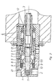
- the device shown in the drawing is used for supplying a gaseous and / or liquid medium to a rotating printing system. It consists essentially of a stationary sealing head housing 1 with a connection opening 2 for the medium, to which a connecting line 2.1 extending in the interior of the sealing head housing 1 connects. Furthermore, it has a likewise arranged in the interior of the sealing head housing 1 and in communication with the pressure system tubular rotor 3, which is supported by two rolling bearings 4 on the stationary sealing head housing 1.
- a stator seal 5 is arranged, while at the end of the rotor 3, a rotor seal 6 is provided, wherein the stator seal 5 and the rotor seal 6 are arranged coaxially to the rotor 3 and abut each other with their end faces.
- the end faces can - as in the embodiment - be designed plan or have a conical or similarly suitable shape.
- a thermally adjustable expansion element 7 is arranged, which directly performs a temperature-dependent adjustment of the axially mutual position of the stator and rotor seal 5, 6.
- This adjustment takes place in the sense that at an increase in the temperature in the region of the seals 5, 6, whereby they are subjected to increased wear, they are relieved by a minimal increase in their mutual distance, but without separation of the two seals 5, 6 from each other. This relief takes place in practice in the micrometer range.
- the expansion element 7 is for this purpose formed by a sleeve part which is fixed at its end facing the pressure system relative to the sealing head housing 1. With its stator seal 5 facing the end of the expansion element 7 is against a standing with the stator seal 5 in connection coupling ring 8. By this type of connection, the entire length of the expansion element 7 can largely be used for a thermally induced change in length and thus an adjustment of the seals 5, 6.
- the expansion element 7 may additionally be provided at least on its inner surface with a surface coating for absorbing heat radiation, whereby a faster heat absorption and thus a faster control mechanism is achieved.
- the coupling ring 8 is the expansion element 7 under the action of springs 9 without play. Furthermore, the coupling ring 8 encloses an axially displaceably mounted seal carrier 10 which receives the stator seal 5 in the end face and which presses this stator seal 5 against the axially fixed rotor seal 6 under the force of a stator spring 11.
- the seal carrier 10 is additionally provided with a radially to the coupling ring 8 projecting annular collar 10.1, wherein the coupling ring 8 and the seal carrier 10 are designed in detail so that between them at regular operating temperature, a narrow annular gap is present.
- the coupling ring 8 is made of a material of low coefficient of thermal expansion, while the seal carrier 10 is made of a material of the opposite large thermal expansion coefficient. Therefore, when heating occurs, preferably the seal carrier 10 also expands radially, whereby the annular gap is reduced until there is a frictional engagement between the seal carrier 10 and the coupling ring 8. From this point on, the seal carrier 10 is taken over the coupling ring 8 of the enlarging in its length expansion element 7, so that the stator seal 5 is slightly lifted from the rotor seal 6, but the system is tuned so that thereby between the two seals 5, 6 no gap arises. This ensures that no particles promoting the wear between the seals 5, 6 can penetrate between the rotor seal and the stator seal 5, 6.
- the outer diameter of the mounted in the seal head housing 1 part of the seal carrier 10 corresponds to the diameter of the rotor 3 receiving rotor bore. Furthermore, the bore diameter of the rotor seal 6 and the stator seal 5 are the same size. This rules out that - for example, in pressure fluctuations - additional, the actual control mechanism disturbing forces on the seals 5, 6 can influence.
- a sealing gap 12 is arranged with an annular channel, through a barrier medium such as. Compressed air is introduced, and at least partially has connection to the leakage connection.
- a further embodiment of the invention is shown in which between the expansion element and the movably mounted seal carrier 10 with respect to their length rotatably adjustable, thermally actuated clutch is arranged.
- the clutch is formed by two rotatably mutually adjustable clutch plates 16,17, one of which is designed as a wedge disk with circumferentially extending wedge surfaces 17.1.
- the second clutch plate 17 has axially projecting, not visible in the drawing cams, which are provided for engagement with the wedge surface 17.1.
- the clutch discs 16,17 are rotatably adjusted by means of one end connected to one of the clutch plates, spiral bi-metal element 18.
- the clutch plates 16,17 are aligned so that the lowest possible axial height of the two clutch plates results.
- the one clutch disc 17 rests on the expansion element 7 and is rotatable.
- the bi-metal element 18 holds at room temperature, the second clutch plate 17 in a position in which results in a minimum length of the coupling and no contact of the second clutch disc with the axially movable seal or the corresponding seal carrier 10.
- a relief ring 14 is arranged between coupling ring and seal carrier 10.
- the coupling ring 8 consists of a material of low coefficient of thermal expansion and the relief ring 14 of a material of contrast, a large coefficient of thermal expansion, wherein at regular Operating temperature between the coupling ring 8 and the relief ring 14, a narrow annular gap is present.
- the relief ring 14 is permanently connected by means of springs 15 on the front side of the seal carrier 10 via a specially shaped annular collar 14.1, wherein the temperature level is transmitted from the seal carrier 10 to the relief ring 14 by metallic contact and heat radiation.
- the relief ring 14 is permanently pressed against the seal carrier 10.
- the temperature-dependent load control between the stator and rotor seal is only effective when between relief ring 14 and coupling ring 8 is eliminated due to heating of the narrow, radial gap, so that a frictional engagement occurs and in addition a change in length of the expansion sleeve 7 takes place.
- the difference to the solution already described above is that a separation of the active surfaces for the coupling and unloading is made. In the solution described above, however, the coupling and discharge takes place via the adjacent surface between the coupling ring 8 and seal carrier 10th
- this modified embodiment provides for a coupling between the coupling ring 8 and the relief ring 14.
- the relief takes place between the seal carrier 10 and the annular collar 14.1 on the relief ring 14. This allows a better mobility of the seal carrier 10 and thus a more favorable reliability of the seal.
Landscapes
- Engineering & Computer Science (AREA)
- General Engineering & Computer Science (AREA)
- Mechanical Engineering (AREA)
- Joints Allowing Movement (AREA)
- Sealing Using Fluids, Sealing Without Contact, And Removal Of Oil (AREA)
- Mechanical Sealing (AREA)
- Nozzles (AREA)
- Coating Apparatus (AREA)
- Toys (AREA)
- Filling Or Discharging Of Gas Storage Vessels (AREA)
- Turbine Rotor Nozzle Sealing (AREA)
Claims (16)
- Dispositif permettant d'acheminer un fluide liquide et/ou gazeux à un système rotatif sous pression dans lequel:- un boîtier de tête d'étanchéité (1) est fixe et présente pour le fluide une ouverture de raccordement (2) à laquelle fait suite une conduite de liaison (2.1) située à l'intérieur du boîtier (1),- un rotor annulaire (3) est situé également à l'intérieur du boîtier (1) et relié au système de pression,- un joint d'étanchéité de stator (5) est monté à l'extrémité de la conduite de liaison (2.1) et un joint d'étanchéité de rotor (6) est monté à l'extrémité du rotor (3), ces deux joints (5, 6) étant coaxiaux au rotor (3) et appliqués l'un sur l'autre,- dans la zone des joints d'étanchéité de stator et de rotor (5, 6) est disposé un élément de dilatation (7) soumis à l'action de la chaleur et qui produit en fonction de celle-ci un déplacement de la position relative et/ou de la charge des joints d'étanchéité de stator et de rotor (5, 6),caractérisé en ce que l'élément de dilatation (7) est constitué par une partie de douille qui, à son extrémité située à côté du système de pression, est fixée par rapport au boîtier de tête d'étanchéité (1), tandis que par son extrémité située du côté du joint d'étanchéité de stator (5) elle est appliquée sur une bague d'accouplement (8) qui, quand la température augmente, est en liaison avec le joint d'étanchéité de stator (5).
- Dispositif selon la revendication 1, caractérisé en ce que l'élément de dilatation (7) présente au moins sur sa surface interne un revêtement absorbant le rayonnement thermique et/ou une structure augmentant la surface.
- Dispositif selon la revendication 1 ou 2, caractérisé en ce que la bague d'accouplement (8) est appliquée par la force d'un ressort sur l'élément de dilatation (7).
- Dispositif selon au moins une des revendications 1 à 3, caractérisé en ce que la bague d'accouplement (8) entoure un support de joint d'étanchéité (10) portant le joint d'étanchéité de stator (5) qui peut coulisser axialement et, sous l'action d'un ressort de stator (11), ce support applique le joint d'étanchéité de stator (5) sur le joint d'étanchéité de rotor (6) axialement fixe.
- Dispositif selon la revendication 4, caractérisé en ce que le support de joint d'étanchéité (10) présente un collet annulaire (10.1) faisant saillie radialement en direction de la bague d'accouplement (8).
- Dispositif selon la revendication 4 ou 5, caractérisé en ce que la bague d'accouplement (8) est faite d'un matériau à faible coefficient de dilatation thermique et le support de joint d'étanchéité (10) est fait d'un matériau de coefficient de dilatation thermique plus élevé, une fente annulaire étroite existant à une température de fonctionnement régulière entre la bague d'accouplement (8) et le support de joint d'étanchéité (10).
- Dispositif selon au moins une des revendications 4 à 6, caractérisé en ce que le collet annulaire (10.1) du support de j oint d'étanchéité (10) a son extrémité en regard du joint d'étanchéité de stator (5) qui s'amincit en forme de cône.
- Dispositif selon au moins une des revendications 1 à 7, caractérisé en ce que le diamètre externe de la partie du support de joint d'étanchéité (10) montée dans le boîtier de tête d'étanchéité (1) correspond au diamètre de l'alésage accueillant le rotor (3), les diamètres du joint d'étanchéité de rotor (6) et du joint d'étanchéité de stator (5) étant égaux.
- Dispositif selon au moins une des revendications 1 à 8, caractérisé en ce que devant le premier et derrière le dernier des paliers (4) se trouve une fente d'étanchéité (12) avec un canal annulaire dans lequel peut être introduit un fluide de blocage, par exemple de l'air comprimé, et qui a au moins partiellement une liaison avec le raccord de fuite.
- Dispositif selon au moins une des revendications 1 à 9, caractérisé en ce que le joint d'étanchéité de rotor (6) est sécurisé axialement par un collet et positionné par rapport à cette sécurisation par l'intermédiaire d'un élément élastique
- Dispositif selon au moins une des revendications 4 à 10, caractérisé en ce qu'entre l'élément de dilatation (7) et le support d'étanchéité (10) mobile, est disposé un accouplement actionné thermiquement et qui peut être réglé en rotation en ce qui concerne sa longueur.
- Dispositif selon la revendication 11, caractérisé en ce que l'accouplement est constitué de deux disques d'accouplement (16, 17), mobiles en rotation l'un par rapport à l'autre, et dont l'un au moins est un disque en coin avec une portée périphérique en coin (17.1).
- Dispositif selon la revendication 12, caractérisé en ce que les disques d'accouplement (16, 17) peuvent être déplacés chacun en rotation par l'intermédiaire d'un élément bilame en forme de spirale raccordé par chaque extrémité à un des disques d'accouplement.
- Dispositif selon la revendication 1 à 10, caractérisé en ce qu'une bague de décharge (14) est montée entre la bague d'accouplement (8) et le support de joint d'étanchéité (10).
- Dispositif selon la revendication 14, caractérisé en ce que la bague d'accouplement (8) est faite d'un matériau à faible coefficient de dilatation et la bague de décharge (14) est faite d'un matériau à coefficient de dilatation plus élevé, une fente annulaire étroite existant entre la bague (8) et la bague (14) à une température de fonctionnement régulière.
- Dispositif selon la revendication 15, caractérisé en ce que la bague de décharge (14) est, par l'intermédiaire de ressorts (15), appliquée en permanence frontalement sur le support de joint d'étanchéité (10) par l'intermédiaire d'un collet annulaire (14.1) de forme spécifique, et le niveau de température est transmis du support de joint d'étanchéité (10) à la bague de décharge (14) par contact métallique et rayonnement thermique.
Applications Claiming Priority (3)
| Application Number | Priority Date | Filing Date | Title |
|---|---|---|---|
| DE10256537A DE10256537A1 (de) | 2002-12-04 | 2002-12-04 | Vorrichtung zum Zuführen eines gasförmigen und/oder flüssigen Mediums zu einem rotierenden Drucksystem |
| DE10256537 | 2002-12-04 | ||
| PCT/DE2003/004011 WO2004051130A1 (fr) | 2002-12-04 | 2003-12-04 | Dispositif permettant d'acheminer un milieu liquide et/ou gazeux a un systeme rotatif sous pression |
Publications (2)
| Publication Number | Publication Date |
|---|---|
| EP1567798A1 EP1567798A1 (fr) | 2005-08-31 |
| EP1567798B1 true EP1567798B1 (fr) | 2007-02-21 |
Family
ID=32403693
Family Applications (1)
| Application Number | Title | Priority Date | Filing Date |
|---|---|---|---|
| EP03788856A Expired - Lifetime EP1567798B1 (fr) | 2002-12-04 | 2003-12-04 | Dispositif permettant d'acheminer un milieu liquide et/ou gazeux a un systeme rotatif sous pression |
Country Status (8)
| Country | Link |
|---|---|
| US (1) | US7399001B2 (fr) |
| EP (1) | EP1567798B1 (fr) |
| JP (1) | JP4456001B2 (fr) |
| AT (1) | ATE354762T1 (fr) |
| AU (1) | AU2003293273A1 (fr) |
| DE (2) | DE10256537A1 (fr) |
| ES (1) | ES2279210T3 (fr) |
| WO (1) | WO2004051130A1 (fr) |
Cited By (1)
| Publication number | Priority date | Publication date | Assignee | Title |
|---|---|---|---|---|
| DE102013009759A1 (de) | 2013-06-11 | 2014-12-11 | Christian Maier Gmbh & Co. Kg Maschinenfabrik | Vorrichtung zum Transport von Medien |
Families Citing this family (16)
| Publication number | Priority date | Publication date | Assignee | Title |
|---|---|---|---|---|
| DE102005038459A1 (de) * | 2005-08-13 | 2007-02-22 | Ott-Jakob Gmbh & Co. Spanntechnik Kg | Drehdurchführung mit Leckagesensor |
| DE102005052067A1 (de) * | 2005-10-28 | 2007-05-03 | Georg Springmann Industrie- Und Bergbautechnik Gmbh | Vorrichtung zum Ankuppeln einer Kühlmittelzuführung an eine Walze |
| WO2007084480A2 (fr) * | 2006-01-18 | 2007-07-26 | 3M Innovative Properties Company | Rouleau a arbre libre avec union rotative aerostatique |
| US8002313B2 (en) * | 2006-04-25 | 2011-08-23 | Kci Licensing, Inc. | Inline swivel connection for multi-lumen tubing |
| DE102009036320A1 (de) * | 2009-08-06 | 2011-02-10 | Centrotherm Thermal Solutions Gmbh + Co. Kg | Verbinder für Gas- oder Flüssigkeitsleitungen und dessen Verwendung |
| US9383051B1 (en) | 2012-05-17 | 2016-07-05 | The Boeing Company | Shrouded dynamically sealed rotary coupling |
| CN102853187A (zh) * | 2012-07-13 | 2013-01-02 | 成都依瑞克科技有限公司 | 耐摩型活动旋转连接管 |
| EP3169924B1 (fr) * | 2014-07-18 | 2019-09-25 | Deublin Company | Union rotative actionnée par un piston |
| CN107339534B (zh) * | 2017-08-03 | 2023-02-10 | 无锡市艾可密封技术有限公司 | 一种高速高压液气旋转接头 |
| US10536053B2 (en) * | 2017-09-20 | 2020-01-14 | Upwing Energy, LLC | High speed motor drive |
| CA2982276C (fr) * | 2017-10-13 | 2025-12-09 | Saturn Machine Works Ltd. | Connecteur a pivot |
| DE102018216921B4 (de) * | 2018-10-02 | 2024-11-07 | Eagleburgmann Germany Gmbh & Co. Kg | Gleitringdichtungsanordnung für eine Drehdurchführung |
| US20200217437A1 (en) * | 2019-01-07 | 2020-07-09 | Deublin Company | Rotary joint |
| CN110792778A (zh) * | 2019-11-26 | 2020-02-14 | 无锡博华机电有限公司 | 一种带气体密封结构的高速旋转接头 |
| JP7433078B2 (ja) * | 2020-02-20 | 2024-02-19 | 三菱電機株式会社 | 液冷装置及び液冷装置を備えた回転電機 |
| DE102022108362A1 (de) | 2022-04-07 | 2023-10-12 | Zf Cv Systems Europe Bv | Verbindungsanordnung zur Kopplung von zwei pneumatischen Leitungen |
Family Cites Families (15)
| Publication number | Priority date | Publication date | Assignee | Title |
|---|---|---|---|---|
| US3273592A (en) * | 1966-09-20 | Deubler etal rotating union control valve | ||
| US2805087A (en) * | 1954-01-07 | 1957-09-03 | Perfecting Service Co | Rotary joint with plural non-communicating paths and a floating tubular core |
| US3002769A (en) * | 1958-01-02 | 1961-10-03 | Deublin Co | Rotary union having particular assembly means |
| US3061337A (en) * | 1958-03-05 | 1962-10-30 | Perfecting Service Company | Rotary fluid connector with noncommunicating passageways |
| US3889983A (en) * | 1974-04-15 | 1975-06-17 | Duff Norton Co | Rotary fluid joint |
| FR2470324B1 (fr) | 1979-11-27 | 1985-07-19 | Fmc Europe | Raccord tournant pour le transfert de produits fluides |
| US4817995A (en) * | 1987-02-06 | 1989-04-04 | Deublin Company | Rotating union with replaceable sealing assembly |
| US4976282A (en) * | 1989-04-12 | 1990-12-11 | Deublin Company | Coolant union with fluid actuated seal assembly |
| US5174614A (en) * | 1991-07-03 | 1992-12-29 | Kaleniecki James F | Bearingless rotary mechanical fluid coupling |
| US5169181A (en) * | 1991-12-16 | 1992-12-08 | The Johnson Corporation | Impact resistant rotary joint with glide ring seals |
| DE4203954C1 (en) | 1992-02-11 | 1993-06-17 | Iobb Produktideen Vorausentwicklung Und Problemloesungen Gmbh, 8960 Kempten, De | Rotary feed coupling for pressurised gas or liquid - has sealing gap between sealing surfaces adjusted to allow axial displacement of rotor relative to stator |
| US5538292A (en) * | 1995-01-17 | 1996-07-23 | Midwest Brake Bond Company | Rotary union |
| US5617879A (en) * | 1995-02-17 | 1997-04-08 | Deublin Company | Sealing arrangement for a coolant union having a floating seal assembly |
| US5669636A (en) * | 1995-08-01 | 1997-09-23 | Deublin Company | Floating seal assembly for a bearingless coolant union having air rotation capability |
| DE69825266T2 (de) * | 1998-02-18 | 2005-08-11 | Nippon Pillar Packing Co., Ltd. | Drehkupplung |
-
2002
- 2002-12-04 DE DE10256537A patent/DE10256537A1/de not_active Withdrawn
-
2003
- 2003-12-04 ES ES03788856T patent/ES2279210T3/es not_active Expired - Lifetime
- 2003-12-04 EP EP03788856A patent/EP1567798B1/fr not_active Expired - Lifetime
- 2003-12-04 AT AT03788856T patent/ATE354762T1/de active
- 2003-12-04 WO PCT/DE2003/004011 patent/WO2004051130A1/fr not_active Ceased
- 2003-12-04 AU AU2003293273A patent/AU2003293273A1/en not_active Abandoned
- 2003-12-04 US US10/537,328 patent/US7399001B2/en not_active Expired - Lifetime
- 2003-12-04 JP JP2004556040A patent/JP4456001B2/ja not_active Expired - Fee Related
- 2003-12-04 DE DE50306602T patent/DE50306602D1/de not_active Expired - Lifetime
Cited By (2)
| Publication number | Priority date | Publication date | Assignee | Title |
|---|---|---|---|---|
| DE102013009759A1 (de) | 2013-06-11 | 2014-12-11 | Christian Maier Gmbh & Co. Kg Maschinenfabrik | Vorrichtung zum Transport von Medien |
| EP2813740A2 (fr) | 2013-06-11 | 2014-12-17 | Christian Maier GmbH & Co. KG Maschinenfabrik | Dispositif de transport de fluides |
Also Published As
| Publication number | Publication date |
|---|---|
| WO2004051130A1 (fr) | 2004-06-17 |
| US7399001B2 (en) | 2008-07-15 |
| ES2279210T3 (es) | 2007-08-16 |
| AU2003293273A1 (en) | 2004-06-23 |
| JP4456001B2 (ja) | 2010-04-28 |
| ATE354762T1 (de) | 2007-03-15 |
| JP2006509162A (ja) | 2006-03-16 |
| US20060017283A1 (en) | 2006-01-26 |
| DE50306602D1 (de) | 2007-04-05 |
| EP1567798A1 (fr) | 2005-08-31 |
| DE10256537A1 (de) | 2004-07-22 |
Similar Documents
| Publication | Publication Date | Title |
|---|---|---|
| EP1567798B1 (fr) | Dispositif permettant d'acheminer un milieu liquide et/ou gazeux a un systeme rotatif sous pression | |
| DE3877762T2 (de) | Gleitring-dichtung mit zentriermitteln. | |
| EP1069362B1 (fr) | Jonction rotative pour milieux alternés | |
| DE69921415T2 (de) | Drehring und damit bestückte Gleitringdichtung | |
| DE69025168T2 (de) | Gleitringdichtung | |
| AT391356B (de) | Loesbare kuppelvorrichtung | |
| DE3119247A1 (de) | Rundschalttisch | |
| DE69427646T2 (de) | Dichtung für eine vorrichtung zum filtrieren von polymeren | |
| EP2063156A1 (fr) | Arrangement d'étanchéité double | |
| EP0368024A2 (fr) | Traversée rotative pour deux fluides différents | |
| EP2058085A1 (fr) | Refroidissement d'arbre pour une broche à moteur d'outil | |
| DE102016008824A1 (de) | Wälzlageranordnung und Röntgenröhrenlagerung | |
| DE3925403C2 (de) | Trockengasdichtung | |
| EP0393331A1 (fr) | Dispositif pour amenée d'un fluide à une partie de machine rotative | |
| EP1902239B1 (fr) | Systeme de garniture d'etancheite a bagues coulissantes | |
| EP4334619B1 (fr) | Joint tournant pour fluides multiples | |
| DE102005026648B4 (de) | Werkzeug und Verfahren zur Bearbeitung eines Werkstücks | |
| EP2976533B1 (fr) | Soupape et système de pompe muni d'une soupape | |
| DE3727173C2 (fr) | ||
| DE69417951T2 (de) | Elektrische Hilfskraftlenkvorrichtung | |
| DE4019987C2 (de) | Drehdurchführung | |
| EP0403676A1 (fr) | Joint mécanique | |
| CH616213A5 (fr) | ||
| EP3615266A1 (fr) | Unité d'étanchéité | |
| WO2009077027A1 (fr) | Agencement de garniture d'étanchéité à anneau glissant |
Legal Events
| Date | Code | Title | Description |
|---|---|---|---|
| PUAI | Public reference made under article 153(3) epc to a published international application that has entered the european phase |
Free format text: ORIGINAL CODE: 0009012 |
|
| 17P | Request for examination filed |
Effective date: 20050419 |
|
| AK | Designated contracting states |
Kind code of ref document: A1 Designated state(s): AT BE BG CH CY CZ DE DK EE ES FI FR GB GR HU IE IT LI LU MC NL PT RO SE SI SK TR |
|
| AX | Request for extension of the european patent |
Extension state: AL LT LV MK |
|
| DAX | Request for extension of the european patent (deleted) | ||
| GRAP | Despatch of communication of intention to grant a patent |
Free format text: ORIGINAL CODE: EPIDOSNIGR1 |
|
| GRAC | Information related to communication of intention to grant a patent modified |
Free format text: ORIGINAL CODE: EPIDOSCIGR1 |
|
| GRAS | Grant fee paid |
Free format text: ORIGINAL CODE: EPIDOSNIGR3 |
|
| GRAA | (expected) grant |
Free format text: ORIGINAL CODE: 0009210 |
|
| AK | Designated contracting states |
Kind code of ref document: B1 Designated state(s): AT BE BG CH CY CZ DE DK EE ES FI FR GB GR HU IE IT LI LU MC NL PT RO SE SI SK TR |
|
| PG25 | Lapsed in a contracting state [announced via postgrant information from national office to epo] |
Ref country code: SI Free format text: LAPSE BECAUSE OF FAILURE TO SUBMIT A TRANSLATION OF THE DESCRIPTION OR TO PAY THE FEE WITHIN THE PRESCRIBED TIME-LIMIT Effective date: 20070221 Ref country code: IE Free format text: LAPSE BECAUSE OF FAILURE TO SUBMIT A TRANSLATION OF THE DESCRIPTION OR TO PAY THE FEE WITHIN THE PRESCRIBED TIME-LIMIT Effective date: 20070221 Ref country code: FI Free format text: LAPSE BECAUSE OF FAILURE TO SUBMIT A TRANSLATION OF THE DESCRIPTION OR TO PAY THE FEE WITHIN THE PRESCRIBED TIME-LIMIT Effective date: 20070221 Ref country code: DK Free format text: LAPSE BECAUSE OF FAILURE TO SUBMIT A TRANSLATION OF THE DESCRIPTION OR TO PAY THE FEE WITHIN THE PRESCRIBED TIME-LIMIT Effective date: 20070221 |
|
| REG | Reference to a national code |
Ref country code: GB Ref legal event code: FG4D Free format text: NOT ENGLISH |
|
| REG | Reference to a national code |
Ref country code: SE Ref legal event code: TRGR |
|
| GBT | Gb: translation of ep patent filed (gb section 77(6)(a)/1977) |
Effective date: 20070221 |
|
| REG | Reference to a national code |
Ref country code: CH Ref legal event code: NV Representative=s name: ISLER & PEDRAZZINI AG Ref country code: CH Ref legal event code: EP |
|
| REF | Corresponds to: |
Ref document number: 50306602 Country of ref document: DE Date of ref document: 20070405 Kind code of ref document: P |
|
| REG | Reference to a national code |
Ref country code: IE Ref legal event code: FG4D Free format text: LANGUAGE OF EP DOCUMENT: GERMAN |
|
| PG25 | Lapsed in a contracting state [announced via postgrant information from national office to epo] |
Ref country code: BG Free format text: LAPSE BECAUSE OF EXPIRATION OF PROTECTION Effective date: 20070522 |
|
| ET | Fr: translation filed | ||
| PG25 | Lapsed in a contracting state [announced via postgrant information from national office to epo] |
Ref country code: PT Free format text: LAPSE BECAUSE OF FAILURE TO SUBMIT A TRANSLATION OF THE DESCRIPTION OR TO PAY THE FEE WITHIN THE PRESCRIBED TIME-LIMIT Effective date: 20070723 |
|
| REG | Reference to a national code |
Ref country code: ES Ref legal event code: FG2A Ref document number: 2279210 Country of ref document: ES Kind code of ref document: T3 |
|
| REG | Reference to a national code |
Ref country code: IE Ref legal event code: FD4D |
|
| REG | Reference to a national code |
Ref country code: CH Ref legal event code: PCAR Free format text: ISLER & PEDRAZZINI AG;POSTFACH 1772;8027 ZUERICH (CH) |
|
| PGFP | Annual fee paid to national office [announced via postgrant information from national office to epo] |
Ref country code: TR Payment date: 20070903 Year of fee payment: 5 |
|
| PLBE | No opposition filed within time limit |
Free format text: ORIGINAL CODE: 0009261 |
|
| STAA | Information on the status of an ep patent application or granted ep patent |
Free format text: STATUS: NO OPPOSITION FILED WITHIN TIME LIMIT |
|
| PG25 | Lapsed in a contracting state [announced via postgrant information from national office to epo] |
Ref country code: RO Free format text: LAPSE BECAUSE OF FAILURE TO SUBMIT A TRANSLATION OF THE DESCRIPTION OR TO PAY THE FEE WITHIN THE PRESCRIBED TIME-LIMIT Effective date: 20070221 |
|
| 26N | No opposition filed |
Effective date: 20071122 |
|
| PG25 | Lapsed in a contracting state [announced via postgrant information from national office to epo] |
Ref country code: GR Free format text: LAPSE BECAUSE OF FAILURE TO SUBMIT A TRANSLATION OF THE DESCRIPTION OR TO PAY THE FEE WITHIN THE PRESCRIBED TIME-LIMIT Effective date: 20070522 |
|
| PG25 | Lapsed in a contracting state [announced via postgrant information from national office to epo] |
Ref country code: MC Free format text: LAPSE BECAUSE OF NON-PAYMENT OF DUE FEES Effective date: 20071231 |
|
| PG25 | Lapsed in a contracting state [announced via postgrant information from national office to epo] |
Ref country code: EE Free format text: LAPSE BECAUSE OF FAILURE TO SUBMIT A TRANSLATION OF THE DESCRIPTION OR TO PAY THE FEE WITHIN THE PRESCRIBED TIME-LIMIT Effective date: 20070221 |
|
| PG25 | Lapsed in a contracting state [announced via postgrant information from national office to epo] |
Ref country code: CY Free format text: LAPSE BECAUSE OF FAILURE TO SUBMIT A TRANSLATION OF THE DESCRIPTION OR TO PAY THE FEE WITHIN THE PRESCRIBED TIME-LIMIT Effective date: 20070221 |
|
| PG25 | Lapsed in a contracting state [announced via postgrant information from national office to epo] |
Ref country code: LU Free format text: LAPSE BECAUSE OF NON-PAYMENT OF DUE FEES Effective date: 20071204 |
|
| PG25 | Lapsed in a contracting state [announced via postgrant information from national office to epo] |
Ref country code: HU Free format text: LAPSE BECAUSE OF FAILURE TO SUBMIT A TRANSLATION OF THE DESCRIPTION OR TO PAY THE FEE WITHIN THE PRESCRIBED TIME-LIMIT Effective date: 20070822 |
|
| PG25 | Lapsed in a contracting state [announced via postgrant information from national office to epo] |
Ref country code: TR Free format text: LAPSE BECAUSE OF NON-PAYMENT OF DUE FEES Effective date: 20100922 |
|
| PG25 | Lapsed in a contracting state [announced via postgrant information from national office to epo] |
Ref country code: TR Free format text: LAPSE BECAUSE OF NON-PAYMENT OF DUE FEES Effective date: 20081204 |
|
| REG | Reference to a national code |
Ref country code: FR Ref legal event code: PLFP Year of fee payment: 14 |
|
| REG | Reference to a national code |
Ref country code: FR Ref legal event code: PLFP Year of fee payment: 15 |
|
| REG | Reference to a national code |
Ref country code: FR Ref legal event code: PLFP Year of fee payment: 16 |
|
| PGFP | Annual fee paid to national office [announced via postgrant information from national office to epo] |
Ref country code: CZ Payment date: 20190916 Year of fee payment: 17 Ref country code: FR Payment date: 20190920 Year of fee payment: 17 Ref country code: SK Payment date: 20190917 Year of fee payment: 17 |
|
| PGFP | Annual fee paid to national office [announced via postgrant information from national office to epo] |
Ref country code: NL Payment date: 20191223 Year of fee payment: 17 Ref country code: SE Payment date: 20191220 Year of fee payment: 17 |
|
| PGFP | Annual fee paid to national office [announced via postgrant information from national office to epo] |
Ref country code: BE Payment date: 20191127 Year of fee payment: 17 |
|
| PGFP | Annual fee paid to national office [announced via postgrant information from national office to epo] |
Ref country code: CH Payment date: 20191211 Year of fee payment: 17 Ref country code: AT Payment date: 20191210 Year of fee payment: 17 |
|
| PGFP | Annual fee paid to national office [announced via postgrant information from national office to epo] |
Ref country code: DE Payment date: 20200212 Year of fee payment: 17 Ref country code: ES Payment date: 20200108 Year of fee payment: 17 Ref country code: GB Payment date: 20191220 Year of fee payment: 17 Ref country code: IT Payment date: 20191224 Year of fee payment: 17 |
|
| REG | Reference to a national code |
Ref country code: DE Ref legal event code: R119 Ref document number: 50306602 Country of ref document: DE |
|
| PG25 | Lapsed in a contracting state [announced via postgrant information from national office to epo] |
Ref country code: CZ Free format text: LAPSE BECAUSE OF NON-PAYMENT OF DUE FEES Effective date: 20201204 |
|
| REG | Reference to a national code |
Ref country code: CH Ref legal event code: PL |
|
| REG | Reference to a national code |
Ref country code: SE Ref legal event code: EUG |
|
| REG | Reference to a national code |
Ref country code: NL Ref legal event code: MM Effective date: 20210101 |
|
| REG | Reference to a national code |
Ref country code: AT Ref legal event code: MM01 Ref document number: 354762 Country of ref document: AT Kind code of ref document: T Effective date: 20201204 |
|
| GBPC | Gb: european patent ceased through non-payment of renewal fee |
Effective date: 20201204 |
|
| REG | Reference to a national code |
Ref country code: SK Ref legal event code: MM4A Ref document number: E 1902 Country of ref document: SK Effective date: 20201204 |
|
| REG | Reference to a national code |
Ref country code: BE Ref legal event code: MM Effective date: 20201231 |
|
| PG25 | Lapsed in a contracting state [announced via postgrant information from national office to epo] |
Ref country code: NL Free format text: LAPSE BECAUSE OF NON-PAYMENT OF DUE FEES Effective date: 20210101 |
|
| PG25 | Lapsed in a contracting state [announced via postgrant information from national office to epo] |
Ref country code: AT Free format text: LAPSE BECAUSE OF NON-PAYMENT OF DUE FEES Effective date: 20201204 Ref country code: IT Free format text: LAPSE BECAUSE OF NON-PAYMENT OF DUE FEES Effective date: 20201204 Ref country code: FR Free format text: LAPSE BECAUSE OF NON-PAYMENT OF DUE FEES Effective date: 20201231 |
|
| PG25 | Lapsed in a contracting state [announced via postgrant information from national office to epo] |
Ref country code: LI Free format text: LAPSE BECAUSE OF NON-PAYMENT OF DUE FEES Effective date: 20201231 Ref country code: SE Free format text: LAPSE BECAUSE OF NON-PAYMENT OF DUE FEES Effective date: 20201205 Ref country code: SK Free format text: LAPSE BECAUSE OF NON-PAYMENT OF DUE FEES Effective date: 20201204 Ref country code: CH Free format text: LAPSE BECAUSE OF NON-PAYMENT OF DUE FEES Effective date: 20201231 Ref country code: GB Free format text: LAPSE BECAUSE OF NON-PAYMENT OF DUE FEES Effective date: 20201204 Ref country code: DE Free format text: LAPSE BECAUSE OF NON-PAYMENT OF DUE FEES Effective date: 20210701 |
|
| REG | Reference to a national code |
Ref country code: ES Ref legal event code: FD2A Effective date: 20220207 |
|
| PG25 | Lapsed in a contracting state [announced via postgrant information from national office to epo] |
Ref country code: ES Free format text: LAPSE BECAUSE OF NON-PAYMENT OF DUE FEES Effective date: 20201205 |
|
| PG25 | Lapsed in a contracting state [announced via postgrant information from national office to epo] |
Ref country code: BE Free format text: LAPSE BECAUSE OF NON-PAYMENT OF DUE FEES Effective date: 20201231 |