EP1567798B1 - Device for feeding a gaseous and/or liquid medium to a rotating pressurised system - Google Patents
Device for feeding a gaseous and/or liquid medium to a rotating pressurised system Download PDFInfo
- Publication number
- EP1567798B1 EP1567798B1 EP03788856A EP03788856A EP1567798B1 EP 1567798 B1 EP1567798 B1 EP 1567798B1 EP 03788856 A EP03788856 A EP 03788856A EP 03788856 A EP03788856 A EP 03788856A EP 1567798 B1 EP1567798 B1 EP 1567798B1
- Authority
- EP
- European Patent Office
- Prior art keywords
- seal
- rotor
- stator
- coupling
- ring
- Prior art date
- Legal status (The legal status is an assumption and is not a legal conclusion. Google has not performed a legal analysis and makes no representation as to the accuracy of the status listed.)
- Expired - Lifetime
Links
- 239000007788 liquid Substances 0.000 title claims description 4
- 230000008878 coupling Effects 0.000 claims abstract description 54
- 238000010168 coupling process Methods 0.000 claims abstract description 54
- 238000005859 coupling reaction Methods 0.000 claims abstract description 54
- 238000007789 sealing Methods 0.000 claims description 27
- 239000000463 material Substances 0.000 claims description 12
- 230000001419 dependent effect Effects 0.000 claims description 6
- 230000005855 radiation Effects 0.000 claims description 5
- 230000000694 effects Effects 0.000 claims description 4
- 239000011248 coating agent Substances 0.000 claims description 3
- 238000000576 coating method Methods 0.000 claims description 3
- 230000000903 blocking effect Effects 0.000 claims 1
- 238000006073 displacement reaction Methods 0.000 claims 1
- 230000002093 peripheral effect Effects 0.000 claims 1
- 230000006903 response to temperature Effects 0.000 abstract 2
- 230000008859 change Effects 0.000 description 7
- 239000002184 metal Substances 0.000 description 6
- 230000009467 reduction Effects 0.000 description 5
- 230000007246 mechanism Effects 0.000 description 4
- 230000002349 favourable effect Effects 0.000 description 3
- 238000010438 heat treatment Methods 0.000 description 3
- 238000000926 separation method Methods 0.000 description 3
- 230000009471 action Effects 0.000 description 2
- 230000004888 barrier function Effects 0.000 description 2
- 230000008901 benefit Effects 0.000 description 2
- 238000004891 communication Methods 0.000 description 2
- 239000002245 particle Substances 0.000 description 2
- OKTJSMMVPCPJKN-UHFFFAOYSA-N Carbon Chemical compound [C] OKTJSMMVPCPJKN-UHFFFAOYSA-N 0.000 description 1
- 238000010521 absorption reaction Methods 0.000 description 1
- 238000001816 cooling Methods 0.000 description 1
- 230000003247 decreasing effect Effects 0.000 description 1
- 238000001514 detection method Methods 0.000 description 1
- 238000005516 engineering process Methods 0.000 description 1
- 239000012530 fluid Substances 0.000 description 1
- 229910002804 graphite Inorganic materials 0.000 description 1
- 239000010439 graphite Substances 0.000 description 1
- 230000001050 lubricating effect Effects 0.000 description 1
- 238000005461 lubrication Methods 0.000 description 1
- 238000003754 machining Methods 0.000 description 1
- 230000035515 penetration Effects 0.000 description 1
- 238000007639 printing Methods 0.000 description 1
- 230000001737 promoting effect Effects 0.000 description 1
- 230000001105 regulatory effect Effects 0.000 description 1
- 238000005096 rolling process Methods 0.000 description 1
- 230000035945 sensitivity Effects 0.000 description 1
Images


Classifications
-
- F—MECHANICAL ENGINEERING; LIGHTING; HEATING; WEAPONS; BLASTING
- F16—ENGINEERING ELEMENTS AND UNITS; GENERAL MEASURES FOR PRODUCING AND MAINTAINING EFFECTIVE FUNCTIONING OF MACHINES OR INSTALLATIONS; THERMAL INSULATION IN GENERAL
- F16L—PIPES; JOINTS OR FITTINGS FOR PIPES; SUPPORTS FOR PIPES, CABLES OR PROTECTIVE TUBING; MEANS FOR THERMAL INSULATION IN GENERAL
- F16L27/00—Adjustable joints; Joints allowing movement
- F16L27/08—Adjustable joints; Joints allowing movement allowing adjustment or movement only about the axis of one pipe
- F16L27/0804—Adjustable joints; Joints allowing movement allowing adjustment or movement only about the axis of one pipe the fluid passing axially from one joint element to another
- F16L27/0808—Adjustable joints; Joints allowing movement allowing adjustment or movement only about the axis of one pipe the fluid passing axially from one joint element to another the joint elements extending coaxially for some distance from their point of separation
- F16L27/0824—Adjustable joints; Joints allowing movement allowing adjustment or movement only about the axis of one pipe the fluid passing axially from one joint element to another the joint elements extending coaxially for some distance from their point of separation with ball or roller bearings
- F16L27/0828—Adjustable joints; Joints allowing movement allowing adjustment or movement only about the axis of one pipe the fluid passing axially from one joint element to another the joint elements extending coaxially for some distance from their point of separation with ball or roller bearings having radial bearings
Definitions
- the invention relates to a device for supplying a gaseous and / or liquid medium to a rotating pressure system, consisting of a stationary sealing head housing with a connection opening for the medium, followed by a running inside the sealing head housing connecting line, as well as with a likewise in the interior of the sealing head housing arranged with the pressure system in communication standing tubular rotor, further comprising a arranged at the end of the connecting line stator seal and arranged at the end of the rotor rotor seal, wherein the stator seal and the rotor seal are arranged coaxially to the rotor and abut against each other, and wherein in the Stator and rotor seal on thermally influenced expansion element, which makes a temperature-dependent adjustment of the mutual position and / or load of stator and rotor seal, characterized in that the expansion element is formed by a sleeve member which is fixed at its end facing the pressure system towards the seal head housing and with its end facing the stator seal rests against a standing at an elevated temperature with
- Devices of this type are used, for example, in the form of sealing heads or rotary feedthroughs of the fluid transfer from stationary to rotating machine components and / or vice versa. Due to the technical advancement, the requirements for rotary unions are steadily increasing. Especially in machine tools, the spindle speeds have within a decade of usually 4,000 to 6,000 rpm. at 20,000 to 50,000 rpm. elevated. In addition, the pressures of the media are constantly growing. Minimal lubrication and new applications, e.g. the blow-off of machining residues in the graphite chip by means of compressed air by feeding the medium into the tool are made extreme demands, especially on the seals of the rotary unions.
- the invention has for its object to provide a device of the type mentioned in the form of a rotary feedthrough, which achieves a long service life in a variety of applications and this has an intrinsic safety, so that regardless of the operating condition, medium and external conditions safe operation and a long life are guaranteed. Decisive for this is a reduction in the sealing and bearing load with the lowest possible leakage current.
- a thermally-influenced expansion element is arranged, which is formed by a sleeve part, which is fixed at its end facing the pressure system towards the seal head housing and facing with his the stator seal End rests against a at elevated temperature with the stator seal in connection with the coupling ring.
- the advantage achieved by the invention consists essentially in the fact that very short control times are achieved. On the one hand, a very sensitive control over the change in length is achieved. On the other hand, the large force resulting from the change in length has a predominant influence on the control behavior, regardless of the media pressure. Another advantage is the almost unlimited and wear-free repeatability of thermally induced Connectn Sungsvorgarigs.
- the expansion element can be provided at least on its inner circumferential surface with a heat radiation absorbing surface coating.
- a further advantageous embodiment of the invention is that the coupling ring encloses a stator seal bearing, axially displaceably mounted seal carrier which presses the stator seal against the axially fixed rotor seal under the force of a stator.
- the seal carrier has a radially to the coupling ring projecting annular collar.
- the coupling ring consists of a material of low thermal expansion coefficient and the seal carrier of a material of contrast, large thermal expansion coefficient, wherein at regular operating temperature between the coupling ring and the seal carrier a narrow annular gap is present , This ensures that the stator seal is applied during normal operation under the pressure of the stator of the rotor seal. Only with an intervention of the scheme required temperature rise occurs between the coupling ring and the seal carrier a frictional engagement, which then the expansion element on the coupling ring and the seal carrier can act on the stator seal in the sense that a discharge of the sealing surface occurs, but without a gap arises because of the penetration of particles and the resulting wear is undesirable.
- the outer diameter of the sealing head housing mounted part of the seal carrier diameter corresponds to the rotor receiving rotor bore and the bore diameter of the rotor seal and the stator seal are the same size. As a result, these axially attacking forces cancel each other.
- the rotor seal does not run after the stator seal has been retracted due to the control, the rotor seal is axially secured by means of a collar and positioned against this fuse by means of a spring element.
- a sealing gap is arranged with an annular channel before the first and after the last of the camp, in which a barrier medium with overpressure, eg compressed air is introduced and at least partially has connection to the leakage connection.
- a barrier medium with overpressure eg compressed air
- a further advantageous embodiment of the invention is characterized in that between the expansion element and the movably mounted seal carrier with respect to their length rotatably adjustable, thermally actuated coupling is arranged.
- the coupling of two rotatably mutually adjustable clutch plates is formed, of which at least one is designed as a wedge disk with one or more peripherally extending wedge surfaces.
- the clutch discs can be rotationally adjusted by means of an end connected to each of the clutch discs, spiral bi-metal element.
- the clutch discs are positioned against each other so that there is a lowest possible axial height of the two clutch discs. While a clutch disc rests on the expander and is rotatable, the second clutch disc is in contact with the first.
- the bi-metal element which is also connected to the second clutch disc, has rotated it into a position in which results in a minimum length of the clutch and there is no contact of the second clutch disc with the axially movable seal or the corresponding seal carrier.
- the second clutch disc is rotated so far on the wedge surfaces until contact with the axially movable seal or the corresponding seal carrier exists. Due to a small wedge angle in the area of self-locking, no further change in position occurs in the direction of rotation even at high axial load.
- the length expansion of the thermal expansion element now has a direct effect on the position or force reduction of the seal.
- a relief ring is arranged between the coupling ring and seal carrier.
- the coupling ring expediently consists of a material of low coefficient of thermal expansion and the relief ring of a material of the other hand, a large thermal expansion coefficient, wherein at regular operating temperature between the coupling ring and the relief ring, a narrow annular gap is present.
- the relief ring permanently applied by means of springs on the front side of the seal carrier on a specially shaped annular collar and is transmitted by metallic contact and thermal radiation, the temperature level of the seal carrier on the discharge ring.
- the relief ring is permanently pressed against the seal carrier.
- the temperature-dependent load control between the stator and rotor seal becomes effective only when between the relief ring and coupling ring due to heating of the narrow, radial gap is eliminated, so that a frictional engagement occurs and in addition there is a change in length of the expansion sleeve.
- the difference to the solution already described above is that a separation of the active surfaces for the coupling and unloading is made. In the solution described above, however, the coupling and discharge takes place via the adjacent surface between the coupling ring and seal carrier.
- this modified embodiment provides for a coupling between the coupling ring and the relief ring and the relief takes place between the seal carrier and the annular collar on the relief ring. This allows a better mobility of the seal carrier and thus a more favorable reliability of the seal.
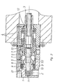
- the device shown in the drawing is used for supplying a gaseous and / or liquid medium to a rotating printing system. It consists essentially of a stationary sealing head housing 1 with a connection opening 2 for the medium, to which a connecting line 2.1 extending in the interior of the sealing head housing 1 connects. Furthermore, it has a likewise arranged in the interior of the sealing head housing 1 and in communication with the pressure system tubular rotor 3, which is supported by two rolling bearings 4 on the stationary sealing head housing 1.
- a stator seal 5 is arranged, while at the end of the rotor 3, a rotor seal 6 is provided, wherein the stator seal 5 and the rotor seal 6 are arranged coaxially to the rotor 3 and abut each other with their end faces.
- the end faces can - as in the embodiment - be designed plan or have a conical or similarly suitable shape.
- a thermally adjustable expansion element 7 is arranged, which directly performs a temperature-dependent adjustment of the axially mutual position of the stator and rotor seal 5, 6.
- This adjustment takes place in the sense that at an increase in the temperature in the region of the seals 5, 6, whereby they are subjected to increased wear, they are relieved by a minimal increase in their mutual distance, but without separation of the two seals 5, 6 from each other. This relief takes place in practice in the micrometer range.
- the expansion element 7 is for this purpose formed by a sleeve part which is fixed at its end facing the pressure system relative to the sealing head housing 1. With its stator seal 5 facing the end of the expansion element 7 is against a standing with the stator seal 5 in connection coupling ring 8. By this type of connection, the entire length of the expansion element 7 can largely be used for a thermally induced change in length and thus an adjustment of the seals 5, 6.
- the expansion element 7 may additionally be provided at least on its inner surface with a surface coating for absorbing heat radiation, whereby a faster heat absorption and thus a faster control mechanism is achieved.
- the coupling ring 8 is the expansion element 7 under the action of springs 9 without play. Furthermore, the coupling ring 8 encloses an axially displaceably mounted seal carrier 10 which receives the stator seal 5 in the end face and which presses this stator seal 5 against the axially fixed rotor seal 6 under the force of a stator spring 11.
- the seal carrier 10 is additionally provided with a radially to the coupling ring 8 projecting annular collar 10.1, wherein the coupling ring 8 and the seal carrier 10 are designed in detail so that between them at regular operating temperature, a narrow annular gap is present.
- the coupling ring 8 is made of a material of low coefficient of thermal expansion, while the seal carrier 10 is made of a material of the opposite large thermal expansion coefficient. Therefore, when heating occurs, preferably the seal carrier 10 also expands radially, whereby the annular gap is reduced until there is a frictional engagement between the seal carrier 10 and the coupling ring 8. From this point on, the seal carrier 10 is taken over the coupling ring 8 of the enlarging in its length expansion element 7, so that the stator seal 5 is slightly lifted from the rotor seal 6, but the system is tuned so that thereby between the two seals 5, 6 no gap arises. This ensures that no particles promoting the wear between the seals 5, 6 can penetrate between the rotor seal and the stator seal 5, 6.
- the outer diameter of the mounted in the seal head housing 1 part of the seal carrier 10 corresponds to the diameter of the rotor 3 receiving rotor bore. Furthermore, the bore diameter of the rotor seal 6 and the stator seal 5 are the same size. This rules out that - for example, in pressure fluctuations - additional, the actual control mechanism disturbing forces on the seals 5, 6 can influence.
- a sealing gap 12 is arranged with an annular channel, through a barrier medium such as. Compressed air is introduced, and at least partially has connection to the leakage connection.
- a further embodiment of the invention is shown in which between the expansion element and the movably mounted seal carrier 10 with respect to their length rotatably adjustable, thermally actuated clutch is arranged.
- the clutch is formed by two rotatably mutually adjustable clutch plates 16,17, one of which is designed as a wedge disk with circumferentially extending wedge surfaces 17.1.
- the second clutch plate 17 has axially projecting, not visible in the drawing cams, which are provided for engagement with the wedge surface 17.1.
- the clutch discs 16,17 are rotatably adjusted by means of one end connected to one of the clutch plates, spiral bi-metal element 18.
- the clutch plates 16,17 are aligned so that the lowest possible axial height of the two clutch plates results.
- the one clutch disc 17 rests on the expansion element 7 and is rotatable.
- the bi-metal element 18 holds at room temperature, the second clutch plate 17 in a position in which results in a minimum length of the coupling and no contact of the second clutch disc with the axially movable seal or the corresponding seal carrier 10.
- a relief ring 14 is arranged between coupling ring and seal carrier 10.
- the coupling ring 8 consists of a material of low coefficient of thermal expansion and the relief ring 14 of a material of contrast, a large coefficient of thermal expansion, wherein at regular Operating temperature between the coupling ring 8 and the relief ring 14, a narrow annular gap is present.
- the relief ring 14 is permanently connected by means of springs 15 on the front side of the seal carrier 10 via a specially shaped annular collar 14.1, wherein the temperature level is transmitted from the seal carrier 10 to the relief ring 14 by metallic contact and heat radiation.
- the relief ring 14 is permanently pressed against the seal carrier 10.
- the temperature-dependent load control between the stator and rotor seal is only effective when between relief ring 14 and coupling ring 8 is eliminated due to heating of the narrow, radial gap, so that a frictional engagement occurs and in addition a change in length of the expansion sleeve 7 takes place.
- the difference to the solution already described above is that a separation of the active surfaces for the coupling and unloading is made. In the solution described above, however, the coupling and discharge takes place via the adjacent surface between the coupling ring 8 and seal carrier 10th
- this modified embodiment provides for a coupling between the coupling ring 8 and the relief ring 14.
- the relief takes place between the seal carrier 10 and the annular collar 14.1 on the relief ring 14. This allows a better mobility of the seal carrier 10 and thus a more favorable reliability of the seal.
Landscapes
- Engineering & Computer Science (AREA)
- General Engineering & Computer Science (AREA)
- Mechanical Engineering (AREA)
- Joints Allowing Movement (AREA)
- Sealing Using Fluids, Sealing Without Contact, And Removal Of Oil (AREA)
- Nozzles (AREA)
- Mechanical Sealing (AREA)
- Turbine Rotor Nozzle Sealing (AREA)
- Filling Or Discharging Of Gas Storage Vessels (AREA)
- Coating Apparatus (AREA)
- Toys (AREA)
Abstract
Description
Die Erfindung betrifft eine Vorrichtung zum Zuführen eines gasförmigen und/oder flüssigen Mediums zu einem rotierenden Drucksystem, bestehend aus einem stillstehenden Dichtkopfgehäuse mit einer Anschlußöffnung für das Medium, an die eine im Innern des Dichtkopfgehäuses verlaufende Verbindungsleitung anschließt, sowie mit einem ebenfalls im Inneren des Dichtkopfgehäuses angeordneten, mit dem Drucksystem in Verbindung stehenden rohrförmigen Rotor, ferner mit einer am Ende der Verbindungsleitung angeordneten Statordichtung und einer am Ende des Rotors angeordneten Rotordichtung, wobei die Statordichtung und die Rotordichtung koaxial zum Rotor angeordnet sind und sich gegeneinander anliegen, und wobei im Bereich der Stator- und Rotordichtung ein thermisch beeinflusstes Dehnelement ist, das eine temperaturabhängige Verstellung der gegenseitigen Lage und/oder Belastung von Stator- und Rotordichtung vornimmt, dadurch gekennzeichnet, daß das Dehnelement von einem Hülsenteil gebildet ist, das an seinem dem Drucksystem zugewandten Ende gegenüber dem Dichtkopfgehäuse fixiert ist und das mit seinem der Statordichtung zugewandten Ende an einem bei erhöhter Temperatur mit der Statordichtung in Verbindung stehenden Kupplungsring anliegt.The invention relates to a device for supplying a gaseous and / or liquid medium to a rotating pressure system, consisting of a stationary sealing head housing with a connection opening for the medium, followed by a running inside the sealing head housing connecting line, as well as with a likewise in the interior of the sealing head housing arranged with the pressure system in communication standing tubular rotor, further comprising a arranged at the end of the connecting line stator seal and arranged at the end of the rotor rotor seal, wherein the stator seal and the rotor seal are arranged coaxially to the rotor and abut against each other, and wherein in the Stator and rotor seal on thermally influenced expansion element, which makes a temperature-dependent adjustment of the mutual position and / or load of stator and rotor seal, characterized in that the expansion element is formed by a sleeve member which is fixed at its end facing the pressure system towards the seal head housing and with its end facing the stator seal rests against a standing at an elevated temperature with the stator seal coupling ring.
Vorrichtungen dieser Art dienen beispielsweise in Form von Dichtköpfen oder Drehdurchführungen der Fluidüberleitung von stehenden in rotierende Maschinenkomponenten und/oder umgekehrt. Durch die technische Weiterentwicklung steigen die Anforderungen an Drehdurchführungen stetig. Insbesondere bei Werkzeugmaschinen haben sich die Spindeldrehzahlen binnen eines Jahrzehnts von üblicherweise 4.000 bis 6.000 U/min. auf 20.000 bis 50.000 U/min. erhöht. Hinzu kommt, daß die Drücke der Medien ständig wachsen. Durch Minimalmengenschmierung und neue Einsatzgebiete, z.B. das Abblasen von Zerspanungsrückständen bei der Graphitzerspanung mittels Druckluft durch Zuführung des Mediums in das Werkzeug werden extreme Anforderungen vor allem an die Dichtungen der Drehdurchführungen gestellt.Devices of this type are used, for example, in the form of sealing heads or rotary feedthroughs of the fluid transfer from stationary to rotating machine components and / or vice versa. Due to the technical advancement, the requirements for rotary unions are steadily increasing. Especially in machine tools, the spindle speeds have within a decade of usually 4,000 to 6,000 rpm. at 20,000 to 50,000 rpm. elevated. In addition, the pressures of the media are constantly growing. Minimal lubrication and new applications, e.g. the blow-off of machining residues in the graphite chip by means of compressed air by feeding the medium into the tool are made extreme demands, especially on the seals of the rotary unions.
Als besonders kritisch für die zunehmenden Anforderungen an die Lebensdauer der Drehdurchführungen zeigen sich Leckage-Ströme, die in die Lager oder in die Spindel gelangen können sowie die Überbelastung der Dichtung, z.B. durch eine irrtümliche Druckbeaufschlagung ohne Durchfluss des Mediums.Particularly critical for the increasing demands on the life of the rotary unions show leakage currents that can get into the bearings or in the spindle and the overload of the seal, for example by an erroneous pressurization without flow of the medium.
Hinzu kommt, dass es unzulässige, oft nicht mehr nachvollziehbare Einsatzbedingungen gibt, die eine deutliche Verringerung der Lebensdauer bisheriger Dreheinführungen verursachen.In addition, there are inadmissible, often incomprehensible operating conditions that cause a significant reduction in the life of previous rotary joints.
Eine genauere Betrachtung der Dichtungsbelastung zeigt, dass im wesentlichen folgende Faktoren großen Einfluss haben:
- Der Druck des Mediums und damit der Druck auf die Dichtflächen
- Die Art des Mediums und dessen Schmierwirkung
- Die Drehzahl und der Durchmesser bzw. die Reibgeschwindigkeit
- Die Durchflussgeschwindigkeit und Art des Mediums und damit dessen Kühlwirkung
- The pressure of the medium and thus the pressure on the sealing surfaces
- The type of medium and its lubricating effect
- The speed and the diameter or the friction speed
- The flow rate and type of medium and thus its cooling effect
Alle diese Faktoren wirken sich unmittelbar auf die Temperaturentwicklung an der Dichtung aus. Geringe Temperatur bedeutet geringe Belastung, hohe Temperatur zeugt von großer Belastung der Dichtung. Als maßgeblich für die Regelung der Dichtungsbelastung wurde deswegen die Temperatur erkannt. In der Sprache der Regeltechnik heißt dies: Die Temperatur ist die Leitgröße.All of these factors directly affect the temperature evolution of the seal. Low temperature means low load, high temperature indicates great stress on the seal. As a result, the temperature was detected as being decisive for the regulation of the sealing load. In the language of control technology, this means that temperature is the guiding variable.
Aus der US-A-4 355 827 ist bereits eine Vorrichtung der eingangs genannten Art bekannt, bei der zwei Dichtkörper mittels eines thermisch wirksamen Bimetalls in Abhängigkeit von sinkenden Temperaturen voneinander separiert werden. Nachteil dieser Lösung ist die fehlende Eignung der Konstruktion für hohe und höchste Drehzahlen des rotierenden Drucksystems sowie die Nichterfassung einer erhöhten Temperatur der Dichtung als entscheidende Leitgröße für die axiale Verstellung der Dichtkörper. Weiter ist aus der DE 4 203 954 C1 eine Drehdurchführung bekannt, bei welcher der Rotor gegenüber dem Stator manuell oder mittels eines thermisch wirksamen Bimetalls in Abhängigkeit von der Temperatur axial verstellt wird. Nachteil dieser Lösung ist die große Abhängigkeit der Regelstrecke und des Regelverhaltens vom Druck bzw. von der Verstellkraft. Zudem werden alle Dichtungsverspannungen unabhängig von der jeweiligen Belastung gleichermaßen verändert.From US-A-4 355 827 a device of the type mentioned is already known, in which two sealing bodies are separated from each other by means of a thermally active bimetal depending on decreasing temperatures. Disadvantage of this solution is the missing Suitability of the design for high and highest speeds of rotation of the rotating pressure system and the non-detection of an elevated temperature of the seal as a key variable for the axial adjustment of the sealing body. Furthermore, from
Der Erfindung liegt die Aufgabe zugrunde, eine Vorrichtung der eingangs genannten Art in Form einer Drehdurchführung zu schaffen, die eine hohe Lebensdauer bei unterschiedlichsten Einsatzfällen erreicht und dazu über eine Eigensicherung verfügt, so daß unabhängig vom Betriebszustand, Medium und äußeren Bedingungen ein sicherer Betrieb und eine lange Lebensdauer gewährleistet sind. Entscheidend ist dafür eine Verminderung der Dichtungs- und Lagerbelastung bei einem zudem möglichst geringen Leckage-Strom.The invention has for its object to provide a device of the type mentioned in the form of a rotary feedthrough, which achieves a long service life in a variety of applications and this has an intrinsic safety, so that regardless of the operating condition, medium and external conditions safe operation and a long life are guaranteed. Decisive for this is a reduction in the sealing and bearing load with the lowest possible leakage current.
Diese Aufgabe wird nach der Erfindung dadurch gelöst, daß im Bereich der Stator- und Rotordichtung ein thermisch beeinflusstes Dehnelement angeordnet ist, das von einem Hülsenteil gebildet ist, das an seinem dem Drucksystem zugewandten Ende gegenüber dem Dichtkopfgehäuse fixiert ist und das mit seinem der Statordichtung zugewandten Ende an einem bei erhöhter Temperatur mit der Statordichtung in Verbindung stehenden Kupplungsring anliegt.This object is achieved according to the invention in that in the region of the stator and rotor seal, a thermally-influenced expansion element is arranged, which is formed by a sleeve part, which is fixed at its end facing the pressure system towards the seal head housing and facing with his the stator seal End rests against a at elevated temperature with the stator seal in connection with the coupling ring.
Der durch die Erfindung erreichte Vorteil besteht im wesentlichen darin, daß sehr kurze Regelzeiten erreicht werden. Einerseits wird eine sehr feinfühlige Regelung über die Längenveränderung erreicht. Andererseits hat die aus der Längenänderung resultierende grosse Kraft überwiegenden Einfluß auf das Regelverhalten und zwar unabhängig vom Mediendruck. Vorteilhaft ist zudem die nahezu unbegrenzte und verschleißfreie Wiederholbarkeit des thermisch bedingten Längenänderungsvorgarigs.The advantage achieved by the invention consists essentially in the fact that very short control times are achieved. On the one hand, a very sensitive control over the change in length is achieved. On the other hand, the large force resulting from the change in length has a predominant influence on the control behavior, regardless of the media pressure. Another advantage is the almost unlimited and wear-free repeatability of thermally induced Längenänderungsvorgarigs.
Da das Dehnelement somit den hinsichtlich eines Temperaturanstiegs kritischen Bereich vollständig umschließt, erfolgt eine schnelle und quantitative Umsetzung eines Temperaturanstiegs in eine Stellgröße und damit eine Lastreduzierung der Dichtungen.Since the expansion element thus the critical with respect to a temperature rise range completely encloses, there is a rapid and quantitative implementation of a temperature increase in a manipulated variable and thus a load reduction of the seals.
Um die Empfindlichkeit der Anordnung noch zu steigern, kann das Dehnelement zumindest an seiner Innenmantelfläche mit einer Wärmestrahlung absorbierenden Oberflächenbeschichtung versehen sein.In order to increase the sensitivity of the arrangement even further, the expansion element can be provided at least on its inner circumferential surface with a heat radiation absorbing surface coating.
Zur Gewährleistung einer möglichst spielfreien Anordnung wird ferner vorgeschlagen, daß der Kupplungsring dem Dehnelement unter Federkraft anliegt.To ensure a backlash-free as possible arrangement is further proposed that the coupling ring bears the expansion element under spring force.
Eine weitere vorteilhafte Ausgestaltung der Erfindung besteht darin, daß der Kupplungsring einen die Statordichtung tragenden, axial verschiebbar gelagerten Dichtungsträger umschließt, der unter der Kraft einer Statorfeder die Statordichtung an die axial feststehende Rotordichtung andrückt. Dazu ist es zweckmäßig, daß der Dichtungsträger einen radial zum Kupplungsring hin vorstehenden Ringbund aufweist.A further advantageous embodiment of the invention is that the coupling ring encloses a stator seal bearing, axially displaceably mounted seal carrier which presses the stator seal against the axially fixed rotor seal under the force of a stator. For this purpose, it is expedient that the seal carrier has a radially to the coupling ring projecting annular collar.
Als wesentliche und damit vorteilhafte Weiterbildung der Erfindung hat sich eine Ausführungsform erwiesen, bei der Kupplungsring aus einem Material von geringem Wärmeausdehnungskoeffizienten und der Dichtungsträger aus einem Material von demgegenüber großem Wärmeausdehnungskoeffizienten besteht, wobei bei regulärer Betriebstemperatur zwischen dem Kupplungsring und dem Dichtungsträger ein enger Ringspalt vorhanden ist. Dadurch wird erreicht, daß die Statordichtung bei regulärem Betrieb unter dem Druck der Statorfeder der Rotordichtung anliegt. Erst bei einem ein Eingreifen der Regelung erforderlich machenden Temperaturanstieg entsteht zwischen dem Kupplungsring und dem Dichtungsträger ein Reibschluß, wodurch dann das Dehnelement über den Kupplungsring und den Dichtungsträger auf die Statordichtung in dem Sinne einwirken kann, daß eine Entlastung der Dichtfläche auftritt, ohne daß jedoch ein Spalt entsteht, der wegen des Eindringens von Partikeln und dem daraus resultierenden Verschleiß unerwünscht ist.As an essential and therefore advantageous embodiment of the invention, an embodiment has been found in the coupling ring consists of a material of low thermal expansion coefficient and the seal carrier of a material of contrast, large thermal expansion coefficient, wherein at regular operating temperature between the coupling ring and the seal carrier a narrow annular gap is present , This ensures that the stator seal is applied during normal operation under the pressure of the stator of the rotor seal. Only with an intervention of the scheme required temperature rise occurs between the coupling ring and the seal carrier a frictional engagement, which then the expansion element on the coupling ring and the seal carrier can act on the stator seal in the sense that a discharge of the sealing surface occurs, but without a gap arises because of the penetration of particles and the resulting wear is undesirable.
Weiter kann es aus Gründen der Wärmeübertragung zweckmäßig sein, wenn der Ringbund des Dichtungsträgers sich zu seinem der Statordichtung zugewandten Ende hin konisch verjüngt.Further, it may be expedient for reasons of heat transfer when the annular collar of the seal carrier tapers conically towards its end facing the stator seal.
Um ein unerwünschtes Eingreifen in den Regelmechanismus, also axial auf die Rotor- und Statordichtung einwirkende, durch den Druck des Mediums hervorgerufene und von diesem abhängige Kräfte zu vermeiden, ist es von Vorteil, wenn der äußere Durchmesser des im Dichtkopfgehäuse gelagerten Teils des Dichtungsträgers dem Durchmesser der den Rotor aufnehmenden Rotorbohrung entspricht und die Bohrungsdurchmesser der Rotordichtung und der Statordichtung gleich groß sind. Dadurch heben sich diese axial angreifenden Kräfte gegenseitig auf.In order to avoid unwanted intervention in the control mechanism, that is, axially acting on the rotor and stator seal, caused by the pressure of the medium and dependent on this forces, it is advantageous if the outer diameter of the sealing head housing mounted part of the seal carrier diameter corresponds to the rotor receiving rotor bore and the bore diameter of the rotor seal and the stator seal are the same size. As a result, these axially attacking forces cancel each other.
Damit die Rotordichtung beim regelungsbedingten Zurückziehen der Statordichtung dieser nicht nachläuft, ist die Rotordichtung mittels Bund axial gesichert und mittels Federelement gegen diese Sicherung positioniert.So that the rotor seal does not run after the stator seal has been retracted due to the control, the rotor seal is axially secured by means of a collar and positioned against this fuse by means of a spring element.
Dabei hat es sich in diesem Zusammenhang noch als günstig erwiesen, wenn vor dem ersten und nach dem letzten der Lager ein Dichtspalt mit einem Ringkanal angeordnet ist, in den ein Sperrmedium mit Überdruck, z.B. Druckluft eingeleitet wird und der zumindest teilweise Verbindung zum Leckageanschluß hat.It has proven in this context still favorable if a sealing gap is arranged with an annular channel before the first and after the last of the camp, in which a barrier medium with overpressure, eg compressed air is introduced and at least partially has connection to the leakage connection.
Eine weitere vorteilhafte Ausgestaltung der Erfindung ist dadurch gekennzeichnet, daß zwischen dem Dehnelement und dem beweglich gelagerten Dichtungsträger eine bezüglich ihrer Länge rotatorisch einstellbare, thermisch betätigte Kupplung angeordnet ist.A further advantageous embodiment of the invention is characterized in that between the expansion element and the movably mounted seal carrier with respect to their length rotatably adjustable, thermally actuated coupling is arranged.
Zweckmäßigerweise ist die Kupplung von zwei drehbar gegeneinander verstellbaren Kupplungsscheiben gebildet, von denen wenigstens eine als Keilscheibe mit einer oder mehreren umfangsseitig verlaufenden Keilflächen ausgebildet ist. Dabei können die Kupplungsscheiben mittels eines endseitig jeweils an einer der Kupplungsscheiben angeschlossenen, spiralförmigen Bi-Metall-Elementes rotatorisch verstellt werden.Conveniently, the coupling of two rotatably mutually adjustable clutch plates is formed, of which at least one is designed as a wedge disk with one or more peripherally extending wedge surfaces. In this case, the clutch discs can be rotationally adjusted by means of an end connected to each of the clutch discs, spiral bi-metal element.
Bei Ruhe bzw. Raumtemperatur befinden sich die Kupplungsscheiben so gegeneinander positioniert, daß sich eine geringstmögliche axiale Höhe der beiden Kupplungsscheiben ergibt. Während eine Kupplungsscheibe auf dem Dehnelement aufliegt und drehbar ist, befindet sich die zweite Kupplungsscheibe in Berührung mit der ersten. Das Bi-Metall-Element, das auch mit der zweiten Kupplungsscheibe verbunden ist, hat diese in eine Position gedreht, in der sich eine minimale Länge der Kupplung ergibt und keine Berührung der zweiten Kupplungsscheibe mit der axial beweglichen Dichtung bzw. dem entsprechenden Dichtungsträger besteht.At rest or room temperature, the clutch discs are positioned against each other so that there is a lowest possible axial height of the two clutch discs. While a clutch disc rests on the expander and is rotatable, the second clutch disc is in contact with the first. The bi-metal element, which is also connected to the second clutch disc, has rotated it into a position in which results in a minimum length of the clutch and there is no contact of the second clutch disc with the axially movable seal or the corresponding seal carrier.
Erhöht sich die Temperatur des unmittelbar am Gleitringdichtspalt angeordneten Bi-Metall-Elements, z.B. auf Grund von Reibungswärme, so wird die zweite Kupplungsscheibe soweit auf den Keilflächen gedreht, bis Kontakt mit der axial beweglichen Dichtung bzw. dem entsprechenden Dichtungsträger besteht. Durch einen geringen Keilwinkel im Bereich der Selbsthemmung tritt nun selbst bei hoher axialer Belastung keine weitere Positionsveränderung in Rotationsrichtung auf. Die Längenausdehnung des Wärmedehnelements wirkt sich nun direkt auf die Position bzw. Kraftreduzierung der Dichtung aus.As the temperature of the bi-metal element located directly on the slip ring seal gap increases, e.g. due to frictional heat, the second clutch disc is rotated so far on the wedge surfaces until contact with the axially movable seal or the corresponding seal carrier exists. Due to a small wedge angle in the area of self-locking, no further change in position occurs in the direction of rotation even at high axial load. The length expansion of the thermal expansion element now has a direct effect on the position or force reduction of the seal.
Gemäß einer weiteren Ausgestaltungsmöglichkeit nach der Erfindung ist zwischen Kupplungsring und Dichtungsträger ein Entlastungsring angeordnet.According to a further embodiment possibility according to the invention, a relief ring is arranged between the coupling ring and seal carrier.
Dazu besteht der Kupplungsring zweckmäßigerweise aus einem Material von geringem Wärmeausdehnungskoeffizienten und der Entlastungsring aus einem Material von demgegenüber großem Wärmeausdehnungskoeffizienten, wobei bei regulärer Betriebstemperatur zwischen dem Kupplungsring und dem Entlastungsring ein enger Ringspalt vorhanden ist.For this purpose, the coupling ring expediently consists of a material of low coefficient of thermal expansion and the relief ring of a material of the other hand, a large thermal expansion coefficient, wherein at regular operating temperature between the coupling ring and the relief ring, a narrow annular gap is present.
Weiter empfiehlt es sich hierbei, daß der Entlastungsring permanent mittels Federn stirnseitig an dem Dichtungsträger über einen speziell geformten ringförmigen Bund anliegt und durch metallischen Kontakt und Wärmestrahlung das Temperaturniveau vom Dichtungsträger auf den Entlastungsring übertragen wird.Further, it is recommended in this case that the relief ring permanently applied by means of springs on the front side of the seal carrier on a specially shaped annular collar and is transmitted by metallic contact and thermal radiation, the temperature level of the seal carrier on the discharge ring.
Der Entlastungsring wird permanent an den Dichtungsträger leicht angedrückt. Die temperaturabhängige Belastungsregelung zwischen Stator- und Rotordichtung wird erst dann wirksam, wenn zwischen Entlastungsring und Kupplungsring infolge Erwärmung der enge, radiale Spalt eliminiert wird, so daß ein Reibschluß entsteht und zusätzlich eine Längenänderung der Dehnhülse erfolgt. Der Unterschied zur voranstehend bereits beschriebenen Lösung besteht darin, daß eine Trennung der Wirkflächen für die Kopplung und Entlastung vorgenommen wird. Bei der bereits beschriebenen Lösung erfolgt die Kopplung und Entlastung dagegen über die angrenzende Fläche zwischen Kupplungsring und Dichtungsträger.The relief ring is permanently pressed against the seal carrier. The temperature-dependent load control between the stator and rotor seal becomes effective only when between the relief ring and coupling ring due to heating of the narrow, radial gap is eliminated, so that a frictional engagement occurs and in addition there is a change in length of the expansion sleeve. The difference to the solution already described above is that a separation of the active surfaces for the coupling and unloading is made. In the solution described above, however, the coupling and discharge takes place via the adjacent surface between the coupling ring and seal carrier.
Diese modizierte Ausführungsform sieht demgegenüber eine Kopplung zwischen Kupplungsring und Entlastungsring vor und die Entlastung erfolgt zwischen Dichtungsträger und dem ringförmigen Bund am Entlastungsring. Dies ermöglicht eine bessere Beweglichkeit des Dichtungsträgers und somit eine günstigere Betriebssicherheit der Dichtung.In contrast, this modified embodiment provides for a coupling between the coupling ring and the relief ring and the relief takes place between the seal carrier and the annular collar on the relief ring. This allows a better mobility of the seal carrier and thus a more favorable reliability of the seal.
Im folgenden wird die Erfindung an einem in der Zeichnung dargestellten Ausführungsbeispiel näher erläutert; es zeigen:
- Fig. 1
- einen Querschnitt durch die Vorrichtung gemäß der Erfindung,
- Fig. 2
- den
Gegenstand nach Figur 1, eingebaut in den Stator einer Maschinenspindel, - Fig. 3
- eine alternative Ausgestaltung in der Fig. 1 entsprechender Darstellung, nur teilweise wiedergegeben,
- Fig. 4
- eine weitere Ausführungsform in der Fig. 1 entsprechender Darstellung.
- Fig. 1
- a cross section through the device according to the invention,
- Fig. 2
- the article according to FIG. 1, installed in the stator of a machine spindle,
- Fig. 3
- an alternative embodiment in the Fig. 1 corresponding representation, only partially reproduced,
- Fig. 4
- a further embodiment in the Fig. 1 corresponding representation.
Die in der Zeichnung dargestellte Vorrichtung dient zum Zuführen eines gasförmigen und/oder flüssigen Mediums zu einem rotierenden Drucksystem. Sie besteht im wesentlichen aus einem stillstehenden Dichtkopfgehäuse 1 mit einer Anschlußöffnung 2 für das Medium, an die eine im Inneren des Dichtkopfgehäuses 1 verlaufende Verbindungsleitung 2.1 anschließt. Ferner weist sie einen ebenfalls im Inneren des Dichtkopfgehäuses 1 angeordneten und mit dem Drucksystem in Verbindung stehenden rohrförmigen Rotor 3 auf, der durch zwei Wälzlager 4 am stillstehenden Dichtkopfgehäuse 1 gelagert ist.The device shown in the drawing is used for supplying a gaseous and / or liquid medium to a rotating printing system. It consists essentially of a stationary
Am Ende der Verbindungsleitung 2.1 ist eine Statordichtung 5 angeordnet, während am Ende des Rotors 3 eine Rotordichtung 6 vorgesehen ist, wobei die Statordichtung 5 und die Rotordichtung 6 koaxial zum Rotor 3 angeordnet sind und sich mit ihren Stirnflächen einander anliegen. Die Stirnflächen konnen dabei - wie im Ausführungsbeispiel - plan ausgebildet sein oder auch eine konische oder ähnlich geeignete Gestalt aufweisen.At the end of the connecting line 2.1, a
Im Bereich der Stator- und Rotordichtung 5, 6 ist ein thermisch verstellbares Dehnelement 7 angeordnet, das unmittelbar eine temperaturabhängige Verstellung der axial gegenseitigen Lage von Stator- und Rotordichtung 5, 6 vornimmt. Diese Verstellung erfolgt in dem Sinne, daß bei einer Erhöhung der Temperatur im Bereich der Dichtungen 5, 6, wodurch diese einem erhöhten Verschleiß unterworfen werden, diese durch eine minimale Erhöhung ihres gegenseitigen Abstandes entlastet werden, ohne daß jedoch eine Trennung der beiden Dichtungen 5, 6 voneinander erfolgt. Diese Entlastung findet in der Praxis im Mikrometer-Bereich statt.In the area of the stator and
Das Dehnelement 7 ist dazu von einem Hülsenteil gebildet, das an seinem dem Drucksystem zugewandten Ende gegenüber dem Dichtkopfgehäuse 1 fixiert ist. Mit seinem der Statordichtung 5 zugewandten Ende liegt das Dehnelement 7 dagegen einem mit der Statordichtung 5 in Verbindung stehenden Kupplungsring 8 an. Durch diese Art des Anschlusses kann weitestgehend die gesamte Länge des Dehnelementes 7 für eine thermisch bedingte Längenänderung und damit eine Verstellung der Dichtungen 5, 6 herangezogen werden.The
Das Dehnelement 7 kann zusätzlich zumindest an seiner Innenmantelfläche mit einer Oberflächenbeschichtung zur Absorbtion von Wärmestrahlung versehen sein, wodurch eine schnellere Wärmeaufnahme und damit ein schnellerer Regelmechanismus erreicht wird.The
Der Kupplungsring 8 liegt dem Dehnelement 7 unter der Einwirkung von Federn 9 spielfrei an. Weiter umschließt der Kupplungsring 8 einen axialverschiebbar gelagerten Dichtungsträger 10, der stirnseitig die Statordichtung 5 in sich aufnimmt und der unter der Kraft einer Statorfeder 11 diese Statordichtung 5 an die axial feststehende Rotordichtung 6 andrückt.The
Der Dichtungsträger 10 ist zusätzlich mit einem radial zum Kupplungsring 8 hin vorstehenden Ringbund 10.1 versehen, wobei der Kupplungsring 8 und der Dichtungsträger 10 im einzelnen so gestaltet sind, daß zwischen ihnen bei regulärer Betriebstemperatur ein enger Ringspalt vorhanden ist.The
Der Kupplungsring 8 besteht aus einem Material von geringem Wärmeausdehnungskoeffizienten, während der Dichtungsträger 10 aus einem Material von dem gegenüber großem Wärmeausdehnungskoeffizienten besteht. Tritt daher eine Erwärmung auf, so dehnt sich vorzugsweise der Dichtungsträger 10 insbesondere auch radial aus, wodurch der Ringspalt verkleinert wird, bis zwischen dem Dichtungsträger 10 und dem Kupplungsring 8 ein Reibschluß besteht. Von diesem Zeitpunkt an wird der Dichtungsträger 10 über den Kupplungsring 8 von dem sich in seiner Länge vergrößernden Dehnelement 7 mitgenommen, so daß die Statordichtung 5 geringfügig von der Rotordichtung 6 abgehoben wird, wobei das System jedoch so abgestimmt ist, daß hierdurch zwischen den beiden Dichtungen 5, 6 kein Spalt entsteht. Dadurch ist sichergestellt, daß keine den Verschleiß zwischen den Dichtungen 5, 6 fördernde Partikel zwischen die Rotor- und die Statordichtung 5, 6 eindringen können.The
In der Folge wird die Temperatur wieder absinken, so daß sowohl das Dehnelement 7 seine Länge verringert als auch der Reibschluß zwischen dem Dichtungsträger 10 und dem Kupplungsring 8 gelöst wird. Bei einem erneuten Temperaturanstieg greift der Regelmechanismus dann in der schon beschriebenen Weise erneut ein.As a result, the temperature will drop again, so that both the
Um im übrigen das Einwirken hydraulischer Kräfte, die von dem Wärmeträgermedium ausgehen, auf die Dichtungen 5, 6 auszuschließen, entspricht der äußere Durchmesser des im Dichtkopfgehäuse 1 gelagerten Teils des Dichtungsträgers 10 dem Durchmesser der den Rotor 3 aufnehmenden Rotorbohrung. Ferner sind die Bohrungsdurchmesser der Rotordichtung 6 und der Statordichtung 5 gleich groß. Dadurch wird ausgeschlossen, daß - beispielsweise bei Druckschwankungen - zusätzliche, den eigentlichen Regelmechanismus störende Kräfte auf die Dichtungen 5, 6 Einfluß haben können.Moreover, in order to exclude the action of hydraulic forces emanating from the heat transfer medium to the
Schließlich ist vor dem ersten und nach dem letzten der beiden Lager 4 ein Dichtspalt 12 mit einem Ringkanal angeordnet, durch ein Sperrmedium wie z.B. Druckluft eingeleitet wird, und der zumindest teilweise Verbindung zum Leckageanschluß hat.Finally, before the first and after the last of the two bearings 4 a
In Fig. 3 ist eine weitere Ausgestaltung der Erfindung dargestellt, bei der zwischen dem Dehnelement und dem beweglich gelagerten Dichtungsträger 10 eine bezüglich ihrer Länge rotatorisch einstellbare, thermisch betätigte Kupplung angeordnet ist. Die Kupplung ist von zwei drehbar gegeneinander verstellbaren Kupplungsscheiben 16,17 gebildet, von denen die eine als Keilscheibe mit umfangsseitig verlaufenden Keilflächen 17.1 ausgebildet ist. Die zweite Kupplungsscheibe 17 weist axial vorstehende, in der Zeichnung nicht ersichtliche Nocken auf, die zur Anlage an der Keilfläche 17.1 vorgesehen sind. Die Kupplungsscheiben 16,17 werden mittels eines endseitig jeweils an einer der Kupplungsscheiben angeschlossenen, spiralförmigen Bi-Metall-Elementes 18 rotatorisch verstellt.In Fig. 3, a further embodiment of the invention is shown in which between the expansion element and the movably mounted
Bei Ruhe bzw. Raumtemperatur sind die Kupplungsscheiben 16,17 so ausgerichtet, daß sich eine geringstmögliche axiale Höhe der beiden Kupplungsscheiben ergibt. Die eine Kupplungsscheibe 17 liegt auf dem Dehnelement 7 auf und ist drehbar. Das Bi-Metall-Element 18 hält bei Raumtemperatur die zweite Kupplungsscheibe 17 in einer Position, in der sich eine minimale Länge der Kupplung ergibt und keine Berührung der zweiten Kupplungsscheibe mit der axial beweglichen Dichtung bzw. dem entsprechenden Dichtungsträger 10 besteht.At rest or room temperature, the
Erhöht sich die Temperatur des unmittelbar am Gleitringdichtspalt angeordneten Bi-Metall-Elements 18, z.B. auf Grund von Reibungswärme, so wird die Kupplungsscheibe 17 soweit auf den Keilflächen gedreht, bis Kontakt mit der axial beweglichen Dichtung bzw. dem entsprechenden Dichtungsträger 10 besteht. Durch einen geringen Keilwinkel im Bereich der Selbsthemmung tritt nun selbst bei hoher axialer Belastung keine weitere Positionsveränderung in Rotationsrichtung auf. Die Längenausdehnung des Wärmedehnelements 7 wirkt sich nun direkt auf die Position bzw. Kraftreduzierung der Dichtung aus.When the temperature of the
Bei der in Fig. 4 dargestellten weiteren Ausgestaltungsmöglichkeit ist zwischen Kupplungsring und Dichtungsträger 10 ein Entlastungsring 14 angeordnet.In the further embodiment option shown in FIG. 4, a
Dazu besteht der Kupplungsring 8 aus einem Material von geringem Wärmeausdehnungskoeffizienten und der Entlastungsring 14 aus einem Material von demgegenüber großem Wärmeausdehnungskoeffizienten, wobei bei regulärer Betriebstemperatur zwischen dem Kupplungsring 8 und dem Entlastungsring 14 ein enger Ringspalt vorhanden ist.For this purpose, the
Der Entlastungsring 14 liegt permanent mittels Federn 15 stirnseitig an dem Dichtungsträger 10 über einen speziell geformten ringförmigen Bund 14.1 an, wobei durch metallischen Kontakt und Wärmestrahlung das Temperaturniveau vom Dichtungsträger 10 auf den Entlastungsring 14 übertragen wird.The
Der Entlastungsring 14 wird permanent an den Dichtungsträger 10 leicht angedrückt. Die temperaturabhängige Belastungsregelung zwischen Stator- und Rotordichtung wird erst dann wirksam, wenn zwischen Entlastungsring 14 und Kupplungsring 8 infolge Erwärmung der enge, radiale Spalt eliminiert wird, so daß ein Reibschluß entsteht und zusätzlich eine Längenänderung der Dehnhülse 7 erfolgt. Der Unterschied zur voranstehend bereits beschriebenen Lösung besteht darin, daß eine Trennung der Wirkflächen für die Kopplung und Entlastung vorgenommen wird. Bei der bereits beschriebenen Lösung erfolgt die Kopplung und Entlastung dagegen über die angrenzende Fläche zwischen Kupplungsring 8 und Dichtungsträger 10.The
Diese modizierte Ausführungsform sieht demgegenüber eine Kopplung zwischen Kupplungsring 8 und Entlastungsring 14 vor. Die Entlastung erfolgt zwischen Dichtungsträger 10 und dem ringförmigen Bund 14.1 am Entlastungsring 14. Dies ermöglicht eine bessere Beweglichkeit des Dichtungsträgers 10 und somit eine günstigere Betriebssicherheit der Dichtung.In contrast, this modified embodiment provides for a coupling between the
Claims (16)
- Apparatus for feeding a gaseous and/or liquid medium to a rotating pressure system, comprising a stationary sealing head housing (1) with at least one connection opening (2) for the medium, to which a connecting conduit (2.1) which extends in the interior of the sealing head housing (1) connects, and a tubular rotor (3) which is also arranged in the interior of the sealing head housing (1) and which is connected to the pressure system, and further comprising a stator seal (5) arranged at the end of the connecting conduit (2.1) and a rotor seal (6) arranged at the end of the rotor (3), wherein the stator seal (5) and the rotor seal (6) are arranged coaxially with respect to the rotor (3) and bear against each other and arranged in the region of the stator and rotor seals (5, 6) is a thermally influenced expansion element (7) which effects temperature-dependent displacement of the mutual position and/or loading of the stator and rotor seals (5, 6),
characterised in that the expansion element (7) is formed by a sleeve portion which is fixed at its end towards the pressure system with respect to the sealing head housing (1) and which with its end towards the stator seal (5) bears against a coupling ring (8) which at elevated temperature is connected to the stator seal (5). - Apparatus according to claim 1 characterised in that the expansion element (7) is provided at least at its inner peripheral surface with a heat radiation-absorbing surface coating and/or surface area-increasing structure.
- Apparatus according to claim 1 or claim 2 characterised in that the coupling ring (8) bears against the expansion element (7) under a spring force.
- Apparatus according to at least one of claims 1 to 3 characterised in that the coupling ring (8) encloses a seal carrier (10) which carries the stator seal (5) and which is axially displaceably supported and which under the force of a stator spring (11) presses the stator seal (5) against the axially stationary rotor seal (6).
- Apparatus according to claim 4 characterised in that the seal carrier (10) has an annular collar (10.1) projecting radially towards the coupling ring (8).
- Apparatus according to claim 4 or claim 5 characterised in that the coupling ring (8) comprises a material with a low coefficient of thermal expansion and the seal carrier (10) comprises a material of a coefficient of thermal expansion which is high in relation thereto and that there is a narrow annular gap at normal operating temperature between the coupling ring (8) and the seal carrier (10).
- Apparatus according to at least one of claims 4 to 6 characterised in that the annular collar (10.1) of the seal carrier (10) tapers conically towards its end towards the stator seal (5).
- Apparatus according to at least one of claims 1 to 7 characterised in that the outside diameter of the part of the seal carrier (10) which is supported in the sealing head housing (1) corresponds to the diameter of the rotor bore accommodating the rotor (3) and the bore diameters of the rotor seal (6) and the stator seal (5) are the same.
- Apparatus according to at least one of claims 1 to 8 characterised in that arranged in front of the first and after the last of the bearings (4) is a sealing gap (12) having an annular passage into which a blocking medium, for example compressed air, is introduced and which at least partially communicates with the leakage connection.
- Apparatus according to at least one of claims 1 to 9 characterised in that the rotor seal (6) is axially secured by means of a collar and is positioned against said securing means by means of a spring element.
- Apparatus according to at least one of claims 4 to 10 characterised in that arranged between the expansion element (7) and the movably supported seal carrier (10) is a thermally actuated coupling which is rotationally adjustable with respect to its length.
- Apparatus according to claim 11 characterised in that the coupling is formed by two coupling discs (16, 17) which are rotatably displaceable with respect to each other and of which one is in the form of a wedge disc with a peripherally extending wedge surface (17.1).
- Apparatus according to claim 12 characterised in that the coupling discs (16, 17) are rotationally displaced by means of a spiral-shaped bimetal element (18) which is connected at each end to a respective one of the coupling discs.
- Apparatus according to claims 1 to 10 characterised in that a stress relief ring (14) is arranged between the coupling ring (8) and the seal carrier (10).
- Apparatus according to claim 14 characterised in that the coupling ring (8) comprises a material with a low coefficient of thermal expansion and the stress relief ring (14) comprises a material with a coefficient of thermal expansion which is high in relation thereto and that there is a narrow annular gap at normal operating temperature between the coupling ring (8) and the stress relief ring (14).
- Apparatus according to claim 15 characterised in that the stress relief ring (14) bears permanently by means of springs (15) at its end against the seal carrier (10) by way of a specially shaped annular collar (14.1) and the temperature level is transmitted from the seal carrier (10) to the stress relief ring (14) by metallic contact and heat radiation.
Applications Claiming Priority (3)
| Application Number | Priority Date | Filing Date | Title |
|---|---|---|---|
| DE10256537 | 2002-12-04 | ||
| DE10256537A DE10256537A1 (en) | 2002-12-04 | 2002-12-04 | Device for supplying a gaseous and / or liquid medium to a rotating pressure system |
| PCT/DE2003/004011 WO2004051130A1 (en) | 2002-12-04 | 2003-12-04 | Device for feeding a gaseous and/or liquid medium to a rotating pressurised system |
Publications (2)
| Publication Number | Publication Date |
|---|---|
| EP1567798A1 EP1567798A1 (en) | 2005-08-31 |
| EP1567798B1 true EP1567798B1 (en) | 2007-02-21 |
Family
ID=32403693
Family Applications (1)
| Application Number | Title | Priority Date | Filing Date |
|---|---|---|---|
| EP03788856A Expired - Lifetime EP1567798B1 (en) | 2002-12-04 | 2003-12-04 | Device for feeding a gaseous and/or liquid medium to a rotating pressurised system |
Country Status (8)
| Country | Link |
|---|---|
| US (1) | US7399001B2 (en) |
| EP (1) | EP1567798B1 (en) |
| JP (1) | JP4456001B2 (en) |
| AT (1) | ATE354762T1 (en) |
| AU (1) | AU2003293273A1 (en) |
| DE (2) | DE10256537A1 (en) |
| ES (1) | ES2279210T3 (en) |
| WO (1) | WO2004051130A1 (en) |
Cited By (1)
| Publication number | Priority date | Publication date | Assignee | Title |
|---|---|---|---|---|
| DE102013009759A1 (en) | 2013-06-11 | 2014-12-11 | Christian Maier Gmbh & Co. Kg Maschinenfabrik | Device for transporting media |
Families Citing this family (16)
| Publication number | Priority date | Publication date | Assignee | Title |
|---|---|---|---|---|
| DE102005038459A1 (en) * | 2005-08-13 | 2007-02-22 | Ott-Jakob Gmbh & Co. Spanntechnik Kg | Rotary feedthrough with leakage sensor |
| DE102005052067A1 (en) * | 2005-10-28 | 2007-05-03 | Georg Springmann Industrie- Und Bergbautechnik Gmbh | Device for coupling a coolant supply to a roller |
| US8172738B2 (en) * | 2006-01-18 | 2012-05-08 | 3M Innovative Properties Company | Dead-shaft roller with aerostatic rotary union |
| US8002313B2 (en) | 2006-04-25 | 2011-08-23 | Kci Licensing, Inc. | Inline swivel connection for multi-lumen tubing |
| DE102009036320A1 (en) * | 2009-08-06 | 2011-02-10 | Centrotherm Thermal Solutions Gmbh + Co. Kg | Connectors for gas or liquid pipes and their use |
| US9383051B1 (en) | 2012-05-17 | 2016-07-05 | The Boeing Company | Shrouded dynamically sealed rotary coupling |
| CN102853187A (en) * | 2012-07-13 | 2013-01-02 | 成都依瑞克科技有限公司 | Wear-resistant movable rotary connecting pipe |
| WO2016011350A1 (en) * | 2014-07-18 | 2016-01-21 | Deublin Company | Piston actuated rotary union |
| CN107339534B (en) * | 2017-08-03 | 2023-02-10 | 无锡市艾可密封技术有限公司 | High-speed high-pressure liquid-gas rotary joint |
| US10312772B2 (en) * | 2017-09-20 | 2019-06-04 | Upwing Energy, LLC | Axial gap generator for powering a magnetic bearing |
| CA2982276C (en) * | 2017-10-13 | 2025-12-09 | Saturn Machine Works Ltd. | Swivel connector |
| DE102018216921B4 (en) * | 2018-10-02 | 2024-11-07 | Eagleburgmann Germany Gmbh & Co. Kg | Mechanical seal arrangement for a rotary union |
| US20200217437A1 (en) * | 2019-01-07 | 2020-07-09 | Deublin Company | Rotary joint |
| CN110792778A (en) * | 2019-11-26 | 2020-02-14 | 无锡博华机电有限公司 | A high-speed rotary joint with gas sealing structure |
| JP7433078B2 (en) * | 2020-02-20 | 2024-02-19 | 三菱電機株式会社 | Liquid cooling device and rotating electric machine equipped with liquid cooling device |
| DE102022108362A1 (en) | 2022-04-07 | 2023-10-12 | Zf Cv Systems Europe Bv | Connection arrangement for coupling two pneumatic lines |
Family Cites Families (15)
| Publication number | Priority date | Publication date | Assignee | Title |
|---|---|---|---|---|
| US3273592A (en) * | 1966-09-20 | Deubler etal rotating union control valve | ||
| US2805087A (en) * | 1954-01-07 | 1957-09-03 | Perfecting Service Co | Rotary joint with plural non-communicating paths and a floating tubular core |
| US3002769A (en) * | 1958-01-02 | 1961-10-03 | Deublin Co | Rotary union having particular assembly means |
| US3061337A (en) * | 1958-03-05 | 1962-10-30 | Perfecting Service Company | Rotary fluid connector with noncommunicating passageways |
| US3889983A (en) * | 1974-04-15 | 1975-06-17 | Duff Norton Co | Rotary fluid joint |
| FR2470324B1 (en) * | 1979-11-27 | 1985-07-19 | Fmc Europe | ROTATING JOINT FOR TRANSFERRING FLUID PRODUCTS |
| US4817995A (en) * | 1987-02-06 | 1989-04-04 | Deublin Company | Rotating union with replaceable sealing assembly |
| US4976282A (en) * | 1989-04-12 | 1990-12-11 | Deublin Company | Coolant union with fluid actuated seal assembly |
| US5174614A (en) * | 1991-07-03 | 1992-12-29 | Kaleniecki James F | Bearingless rotary mechanical fluid coupling |
| US5169181A (en) * | 1991-12-16 | 1992-12-08 | The Johnson Corporation | Impact resistant rotary joint with glide ring seals |
| DE4203954C1 (en) | 1992-02-11 | 1993-06-17 | Iobb Produktideen Vorausentwicklung Und Problemloesungen Gmbh, 8960 Kempten, De | Rotary feed coupling for pressurised gas or liquid - has sealing gap between sealing surfaces adjusted to allow axial displacement of rotor relative to stator |
| US5538292A (en) * | 1995-01-17 | 1996-07-23 | Midwest Brake Bond Company | Rotary union |
| US5617879A (en) * | 1995-02-17 | 1997-04-08 | Deublin Company | Sealing arrangement for a coolant union having a floating seal assembly |
| US5669636A (en) * | 1995-08-01 | 1997-09-23 | Deublin Company | Floating seal assembly for a bearingless coolant union having air rotation capability |
| DE69825266T2 (en) * | 1998-02-18 | 2005-08-11 | Nippon Pillar Packing Co., Ltd. | ROTARY CLUTCH |
-
2002
- 2002-12-04 DE DE10256537A patent/DE10256537A1/en not_active Withdrawn
-
2003
- 2003-12-04 EP EP03788856A patent/EP1567798B1/en not_active Expired - Lifetime
- 2003-12-04 US US10/537,328 patent/US7399001B2/en not_active Expired - Lifetime
- 2003-12-04 WO PCT/DE2003/004011 patent/WO2004051130A1/en not_active Ceased
- 2003-12-04 ES ES03788856T patent/ES2279210T3/en not_active Expired - Lifetime
- 2003-12-04 DE DE50306602T patent/DE50306602D1/en not_active Expired - Lifetime
- 2003-12-04 AU AU2003293273A patent/AU2003293273A1/en not_active Abandoned
- 2003-12-04 AT AT03788856T patent/ATE354762T1/en active
- 2003-12-04 JP JP2004556040A patent/JP4456001B2/en not_active Expired - Fee Related
Cited By (2)
| Publication number | Priority date | Publication date | Assignee | Title |
|---|---|---|---|---|
| DE102013009759A1 (en) | 2013-06-11 | 2014-12-11 | Christian Maier Gmbh & Co. Kg Maschinenfabrik | Device for transporting media |
| EP2813740A2 (en) | 2013-06-11 | 2014-12-17 | Christian Maier GmbH & Co. KG Maschinenfabrik | Device for transporting media |
Also Published As
| Publication number | Publication date |
|---|---|
| AU2003293273A1 (en) | 2004-06-23 |
| EP1567798A1 (en) | 2005-08-31 |
| ATE354762T1 (en) | 2007-03-15 |
| JP4456001B2 (en) | 2010-04-28 |
| DE50306602D1 (en) | 2007-04-05 |
| DE10256537A1 (en) | 2004-07-22 |
| US20060017283A1 (en) | 2006-01-26 |
| JP2006509162A (en) | 2006-03-16 |
| WO2004051130A1 (en) | 2004-06-17 |
| ES2279210T3 (en) | 2007-08-16 |
| US7399001B2 (en) | 2008-07-15 |
Similar Documents
| Publication | Publication Date | Title |
|---|---|---|
| EP1567798B1 (en) | Device for feeding a gaseous and/or liquid medium to a rotating pressurised system | |
| DE3877762T2 (en) | MECHANICAL SEAL WITH CENTERING AGENTS. | |
| EP1069362B1 (en) | Rotatable connection for alternate mediums | |
| DE69921415T2 (en) | Turning ring and thus fitted mechanical seal | |
| DE69025168T2 (en) | Mechanical seal | |
| AT391356B (en) | DETACHABLE COUPLING DEVICE | |
| DE3119247A1 (en) | ROUND SWITCHING TABLE | |
| DE69427646T2 (en) | GASKET FOR A DEVICE FOR FILTERING POLYMERS | |
| EP2063156A1 (en) | Double seal arrangement | |
| EP0368024A2 (en) | Rotating lead-through for two different fluids | |
| EP2058085A1 (en) | Shaft cooling for a machine tool motor spindle | |
| DE102016008824A1 (en) | Rolling bearing assembly and X-ray tube storage | |
| DE3925403C2 (en) | Dry gas seal | |
| EP0393331A1 (en) | Device for conveying a fluid to a rotating machine part | |
| EP1902239B1 (en) | Slide ring seal arrangement | |
| EP4334619B1 (en) | Multimedia rotary union | |
| DE102005026648B4 (en) | Tool and method for machining a workpiece | |
| EP2976533B1 (en) | Valve and pump arrangement with valve | |
| DE3727173C2 (en) | ||
| DE69417951T2 (en) | Electric power steering device | |
| DE4019987C2 (en) | Rotary union | |
| CH616213A5 (en) | ||
| EP3615266A1 (en) | Sealing unit | |
| WO2009077027A1 (en) | Slide ring seal arrangement | |
| DE102004023231B4 (en) | Device with a rotary union for a liquid |
Legal Events
| Date | Code | Title | Description |
|---|---|---|---|
| PUAI | Public reference made under article 153(3) epc to a published international application that has entered the european phase |
Free format text: ORIGINAL CODE: 0009012 |
|
| 17P | Request for examination filed |
Effective date: 20050419 |
|
| AK | Designated contracting states |
Kind code of ref document: A1 Designated state(s): AT BE BG CH CY CZ DE DK EE ES FI FR GB GR HU IE IT LI LU MC NL PT RO SE SI SK TR |
|
| AX | Request for extension of the european patent |
Extension state: AL LT LV MK |
|
| DAX | Request for extension of the european patent (deleted) | ||
| GRAP | Despatch of communication of intention to grant a patent |
Free format text: ORIGINAL CODE: EPIDOSNIGR1 |
|
| GRAC | Information related to communication of intention to grant a patent modified |
Free format text: ORIGINAL CODE: EPIDOSCIGR1 |
|
| GRAS | Grant fee paid |
Free format text: ORIGINAL CODE: EPIDOSNIGR3 |
|
| GRAA | (expected) grant |
Free format text: ORIGINAL CODE: 0009210 |
|
| AK | Designated contracting states |
Kind code of ref document: B1 Designated state(s): AT BE BG CH CY CZ DE DK EE ES FI FR GB GR HU IE IT LI LU MC NL PT RO SE SI SK TR |
|
| PG25 | Lapsed in a contracting state [announced via postgrant information from national office to epo] |
Ref country code: SI Free format text: LAPSE BECAUSE OF FAILURE TO SUBMIT A TRANSLATION OF THE DESCRIPTION OR TO PAY THE FEE WITHIN THE PRESCRIBED TIME-LIMIT Effective date: 20070221 Ref country code: IE Free format text: LAPSE BECAUSE OF FAILURE TO SUBMIT A TRANSLATION OF THE DESCRIPTION OR TO PAY THE FEE WITHIN THE PRESCRIBED TIME-LIMIT Effective date: 20070221 Ref country code: FI Free format text: LAPSE BECAUSE OF FAILURE TO SUBMIT A TRANSLATION OF THE DESCRIPTION OR TO PAY THE FEE WITHIN THE PRESCRIBED TIME-LIMIT Effective date: 20070221 Ref country code: DK Free format text: LAPSE BECAUSE OF FAILURE TO SUBMIT A TRANSLATION OF THE DESCRIPTION OR TO PAY THE FEE WITHIN THE PRESCRIBED TIME-LIMIT Effective date: 20070221 |
|
| REG | Reference to a national code |
Ref country code: GB Ref legal event code: FG4D Free format text: NOT ENGLISH |
|
| REG | Reference to a national code |
Ref country code: SE Ref legal event code: TRGR |
|
| GBT | Gb: translation of ep patent filed (gb section 77(6)(a)/1977) |
Effective date: 20070221 |
|
| REG | Reference to a national code |
Ref country code: CH Ref legal event code: NV Representative=s name: ISLER & PEDRAZZINI AG Ref country code: CH Ref legal event code: EP |
|
| REF | Corresponds to: |
Ref document number: 50306602 Country of ref document: DE Date of ref document: 20070405 Kind code of ref document: P |
|
| REG | Reference to a national code |
Ref country code: IE Ref legal event code: FG4D Free format text: LANGUAGE OF EP DOCUMENT: GERMAN |
|
| PG25 | Lapsed in a contracting state [announced via postgrant information from national office to epo] |
Ref country code: BG Free format text: LAPSE BECAUSE OF EXPIRATION OF PROTECTION Effective date: 20070522 |
|
| ET | Fr: translation filed | ||
| PG25 | Lapsed in a contracting state [announced via postgrant information from national office to epo] |
Ref country code: PT Free format text: LAPSE BECAUSE OF FAILURE TO SUBMIT A TRANSLATION OF THE DESCRIPTION OR TO PAY THE FEE WITHIN THE PRESCRIBED TIME-LIMIT Effective date: 20070723 |
|
| REG | Reference to a national code |
Ref country code: ES Ref legal event code: FG2A Ref document number: 2279210 Country of ref document: ES Kind code of ref document: T3 |
|
| REG | Reference to a national code |
Ref country code: IE Ref legal event code: FD4D |
|
| REG | Reference to a national code |
Ref country code: CH Ref legal event code: PCAR Free format text: ISLER & PEDRAZZINI AG;POSTFACH 1772;8027 ZUERICH (CH) |
|
| PGFP | Annual fee paid to national office [announced via postgrant information from national office to epo] |
Ref country code: TR Payment date: 20070903 Year of fee payment: 5 |
|
| PLBE | No opposition filed within time limit |
Free format text: ORIGINAL CODE: 0009261 |
|
| STAA | Information on the status of an ep patent application or granted ep patent |
Free format text: STATUS: NO OPPOSITION FILED WITHIN TIME LIMIT |
|
| PG25 | Lapsed in a contracting state [announced via postgrant information from national office to epo] |
Ref country code: RO Free format text: LAPSE BECAUSE OF FAILURE TO SUBMIT A TRANSLATION OF THE DESCRIPTION OR TO PAY THE FEE WITHIN THE PRESCRIBED TIME-LIMIT Effective date: 20070221 |
|
| 26N | No opposition filed |
Effective date: 20071122 |
|
| PG25 | Lapsed in a contracting state [announced via postgrant information from national office to epo] |
Ref country code: GR Free format text: LAPSE BECAUSE OF FAILURE TO SUBMIT A TRANSLATION OF THE DESCRIPTION OR TO PAY THE FEE WITHIN THE PRESCRIBED TIME-LIMIT Effective date: 20070522 |
|
| PG25 | Lapsed in a contracting state [announced via postgrant information from national office to epo] |
Ref country code: MC Free format text: LAPSE BECAUSE OF NON-PAYMENT OF DUE FEES Effective date: 20071231 |
|
| PG25 | Lapsed in a contracting state [announced via postgrant information from national office to epo] |
Ref country code: EE Free format text: LAPSE BECAUSE OF FAILURE TO SUBMIT A TRANSLATION OF THE DESCRIPTION OR TO PAY THE FEE WITHIN THE PRESCRIBED TIME-LIMIT Effective date: 20070221 |
|
| PG25 | Lapsed in a contracting state [announced via postgrant information from national office to epo] |
Ref country code: CY Free format text: LAPSE BECAUSE OF FAILURE TO SUBMIT A TRANSLATION OF THE DESCRIPTION OR TO PAY THE FEE WITHIN THE PRESCRIBED TIME-LIMIT Effective date: 20070221 |
|
| PG25 | Lapsed in a contracting state [announced via postgrant information from national office to epo] |
Ref country code: LU Free format text: LAPSE BECAUSE OF NON-PAYMENT OF DUE FEES Effective date: 20071204 |
|
| PG25 | Lapsed in a contracting state [announced via postgrant information from national office to epo] |
Ref country code: HU Free format text: LAPSE BECAUSE OF FAILURE TO SUBMIT A TRANSLATION OF THE DESCRIPTION OR TO PAY THE FEE WITHIN THE PRESCRIBED TIME-LIMIT Effective date: 20070822 |
|
| PG25 | Lapsed in a contracting state [announced via postgrant information from national office to epo] |
Ref country code: TR Free format text: LAPSE BECAUSE OF NON-PAYMENT OF DUE FEES Effective date: 20100922 |
|
| PG25 | Lapsed in a contracting state [announced via postgrant information from national office to epo] |
Ref country code: TR Free format text: LAPSE BECAUSE OF NON-PAYMENT OF DUE FEES Effective date: 20081204 |
|
| REG | Reference to a national code |
Ref country code: FR Ref legal event code: PLFP Year of fee payment: 14 |
|
| REG | Reference to a national code |
Ref country code: FR Ref legal event code: PLFP Year of fee payment: 15 |
|
| REG | Reference to a national code |
Ref country code: FR Ref legal event code: PLFP Year of fee payment: 16 |
|
| PGFP | Annual fee paid to national office [announced via postgrant information from national office to epo] |
Ref country code: CZ Payment date: 20190916 Year of fee payment: 17 Ref country code: FR Payment date: 20190920 Year of fee payment: 17 Ref country code: SK Payment date: 20190917 Year of fee payment: 17 |
|
| PGFP | Annual fee paid to national office [announced via postgrant information from national office to epo] |
Ref country code: NL Payment date: 20191223 Year of fee payment: 17 Ref country code: SE Payment date: 20191220 Year of fee payment: 17 |
|
| PGFP | Annual fee paid to national office [announced via postgrant information from national office to epo] |
Ref country code: BE Payment date: 20191127 Year of fee payment: 17 |
|
| PGFP | Annual fee paid to national office [announced via postgrant information from national office to epo] |
Ref country code: CH Payment date: 20191211 Year of fee payment: 17 Ref country code: AT Payment date: 20191210 Year of fee payment: 17 |
|
| PGFP | Annual fee paid to national office [announced via postgrant information from national office to epo] |
Ref country code: DE Payment date: 20200212 Year of fee payment: 17 Ref country code: ES Payment date: 20200108 Year of fee payment: 17 Ref country code: GB Payment date: 20191220 Year of fee payment: 17 Ref country code: IT Payment date: 20191224 Year of fee payment: 17 |
|
| REG | Reference to a national code |
Ref country code: DE Ref legal event code: R119 Ref document number: 50306602 Country of ref document: DE |
|
| PG25 | Lapsed in a contracting state [announced via postgrant information from national office to epo] |
Ref country code: CZ Free format text: LAPSE BECAUSE OF NON-PAYMENT OF DUE FEES Effective date: 20201204 |
|
| REG | Reference to a national code |
Ref country code: CH Ref legal event code: PL |
|
| REG | Reference to a national code |
Ref country code: SE Ref legal event code: EUG |
|
| REG | Reference to a national code |
Ref country code: NL Ref legal event code: MM Effective date: 20210101 |
|
| REG | Reference to a national code |
Ref country code: AT Ref legal event code: MM01 Ref document number: 354762 Country of ref document: AT Kind code of ref document: T Effective date: 20201204 |
|
| GBPC | Gb: european patent ceased through non-payment of renewal fee |
Effective date: 20201204 |
|
| REG | Reference to a national code |
Ref country code: SK Ref legal event code: MM4A Ref document number: E 1902 Country of ref document: SK Effective date: 20201204 |
|
| REG | Reference to a national code |
Ref country code: BE Ref legal event code: MM Effective date: 20201231 |
|
| PG25 | Lapsed in a contracting state [announced via postgrant information from national office to epo] |
Ref country code: NL Free format text: LAPSE BECAUSE OF NON-PAYMENT OF DUE FEES Effective date: 20210101 |
|
| PG25 | Lapsed in a contracting state [announced via postgrant information from national office to epo] |
Ref country code: AT Free format text: LAPSE BECAUSE OF NON-PAYMENT OF DUE FEES Effective date: 20201204 Ref country code: IT Free format text: LAPSE BECAUSE OF NON-PAYMENT OF DUE FEES Effective date: 20201204 Ref country code: FR Free format text: LAPSE BECAUSE OF NON-PAYMENT OF DUE FEES Effective date: 20201231 |
|
| PG25 | Lapsed in a contracting state [announced via postgrant information from national office to epo] |
Ref country code: LI Free format text: LAPSE BECAUSE OF NON-PAYMENT OF DUE FEES Effective date: 20201231 Ref country code: SE Free format text: LAPSE BECAUSE OF NON-PAYMENT OF DUE FEES Effective date: 20201205 Ref country code: SK Free format text: LAPSE BECAUSE OF NON-PAYMENT OF DUE FEES Effective date: 20201204 Ref country code: CH Free format text: LAPSE BECAUSE OF NON-PAYMENT OF DUE FEES Effective date: 20201231 Ref country code: GB Free format text: LAPSE BECAUSE OF NON-PAYMENT OF DUE FEES Effective date: 20201204 Ref country code: DE Free format text: LAPSE BECAUSE OF NON-PAYMENT OF DUE FEES Effective date: 20210701 |
|
| REG | Reference to a national code |
Ref country code: ES Ref legal event code: FD2A Effective date: 20220207 |
|
| PG25 | Lapsed in a contracting state [announced via postgrant information from national office to epo] |
Ref country code: ES Free format text: LAPSE BECAUSE OF NON-PAYMENT OF DUE FEES Effective date: 20201205 |
|
| PG25 | Lapsed in a contracting state [announced via postgrant information from national office to epo] |
Ref country code: BE Free format text: LAPSE BECAUSE OF NON-PAYMENT OF DUE FEES Effective date: 20201231 |