EP1567735B1 - Textilschalung für eine säule oder einen sockel - Google Patents
Textilschalung für eine säule oder einen sockel Download PDFInfo
- Publication number
- EP1567735B1 EP1567735B1 EP03758384A EP03758384A EP1567735B1 EP 1567735 B1 EP1567735 B1 EP 1567735B1 EP 03758384 A EP03758384 A EP 03758384A EP 03758384 A EP03758384 A EP 03758384A EP 1567735 B1 EP1567735 B1 EP 1567735B1
- Authority
- EP
- European Patent Office
- Prior art keywords
- flexible sheet
- flexible
- sheet element
- longitudinal
- forming tube
- Prior art date
- Legal status (The legal status is an assumption and is not a legal conclusion. Google has not performed a legal analysis and makes no representation as to the accuracy of the status listed.)
- Expired - Lifetime
Links
- 239000004744 fabric Substances 0.000 title abstract description 31
- 238000000034 method Methods 0.000 claims description 14
- 239000002759 woven fabric Substances 0.000 claims description 10
- 239000000463 material Substances 0.000 claims description 9
- 238000005304 joining Methods 0.000 claims description 7
- 238000005520 cutting process Methods 0.000 claims description 5
- 230000009969 flowable effect Effects 0.000 claims description 5
- 239000000835 fiber Substances 0.000 claims description 2
- OKTJSMMVPCPJKN-UHFFFAOYSA-N Carbon Chemical compound [C] OKTJSMMVPCPJKN-UHFFFAOYSA-N 0.000 claims 1
- 229910052799 carbon Inorganic materials 0.000 claims 1
- 230000002706 hydrostatic effect Effects 0.000 abstract 1
- 229910000831 Steel Inorganic materials 0.000 description 4
- 239000010959 steel Substances 0.000 description 4
- 238000003860 storage Methods 0.000 description 4
- 239000000123 paper Substances 0.000 description 3
- 230000003014 reinforcing effect Effects 0.000 description 3
- 238000004519 manufacturing process Methods 0.000 description 2
- -1 polyethylene Polymers 0.000 description 2
- 238000009958 sewing Methods 0.000 description 2
- 238000003466 welding Methods 0.000 description 2
- 229920000049 Carbon (fiber) Polymers 0.000 description 1
- 239000004698 Polyethylene Substances 0.000 description 1
- 239000004743 Polypropylene Substances 0.000 description 1
- 239000004917 carbon fiber Substances 0.000 description 1
- 239000011248 coating agent Substances 0.000 description 1
- 238000000576 coating method Methods 0.000 description 1
- VNWKTOKETHGBQD-UHFFFAOYSA-N methane Chemical compound C VNWKTOKETHGBQD-UHFFFAOYSA-N 0.000 description 1
- 238000004806 packaging method and process Methods 0.000 description 1
- 229920000573 polyethylene Polymers 0.000 description 1
- 229920001155 polypropylene Polymers 0.000 description 1
- 230000002787 reinforcement Effects 0.000 description 1
- 230000037303 wrinkles Effects 0.000 description 1
Images

Classifications
-
- E—FIXED CONSTRUCTIONS
- E04—BUILDING
- E04G—SCAFFOLDING; FORMS; SHUTTERING; BUILDING IMPLEMENTS OR AIDS, OR THEIR USE; HANDLING BUILDING MATERIALS ON THE SITE; REPAIRING, BREAKING-UP OR OTHER WORK ON EXISTING BUILDINGS
- E04G13/00—Falsework, forms, or shutterings for particular parts of buildings, e.g. stairs, steps, cornices, balconies foundations, sills
- E04G13/02—Falsework, forms, or shutterings for particular parts of buildings, e.g. stairs, steps, cornices, balconies foundations, sills for columns or like pillars; Special tying or clamping means therefor
- E04G13/021—Falsework, forms, or shutterings for particular parts of buildings, e.g. stairs, steps, cornices, balconies foundations, sills for columns or like pillars; Special tying or clamping means therefor for circular columns
Definitions
- This invention relates generally to a concrete column and pad forming tube made of a fabric like material for receiving a flowable and settable material poured into the interior of the tube so as to form a round column or pad upon the hardening of the material, and which is characterized by folding flat for storage and shipping, while at the same time being able to be accurately positioned on the job site.
- Concrete column forming tubes are conventionally formed of multiple layers of paper, which are spirally wound around a mandrel and with a wall thickness of about 6 mm so that the tube is rigid and maintains its circular cross section. Because of the large diameters and lengths, transportation and storage is very expensive.
- the patent contemplates an alternative for vertically supporting the tube by cutting a series of notches in the upper end, which are folded outwardly over a circular supporting framework. Again, this would require additional bracing and labor, obviating the benefits of the collapsible form.
- DE-U-9200496 discloses a method of forming concrete columns using mouldable fibre plates.
- the tube for the concrete columns is formed by joining adjacent plates together. The ends of two adjacent plates are joined to form a longitudinal tab to be supported by extra inserts.
- Such forming tubes may be fabricated from fabric with one or more longitudinal tabs running the full length of the tube. Each tab is sandwiched between two vertical support members, which are used to properly locate the tube on the job site, before filling with concrete.
- a prefabricated flexible forming tube for a concrete column or pad comprising: at least one flexible sheet element of specified width characterized in that the flexible sheet element is formed from woven fabric, and one longitudinal edge of said flexible sheet element is arranged in overlapping relationship with either:
- This invention also contemplates the use of a woven fabric of sufficient strength that bulging will not occur, while at the same time being able to fold flat.
- the fabric is joined into a tube by welding, sewing or zippering the edges together.
- the fabric based forming tube is collapsed and folded into a small package to facilitate its storage and transportation.
- the contractor cuts off the exact length of tube required for the column.
- the fabric tab is nailed or screwed between two vertical support members probably made from 75mm by 200mm lumber, and the assembly is placed vertically into position and braced. Concrete is then poured into the fabric tube so that it takes a cylindrical configuration across from the two vertical support members. After the concrete is hardened, the fabric tube can be left in place, or removed at the weld, zipper, or cut with a sharp knife.
- FIGURE 1 is a perspective view of a preferred embodiment of a concrete forming tube used in accordance with the present invention as a concrete column and which is indicated generally at 10.
- the flexible sheet form element, or fabric 14 is joined to form a tube with the outside longitudinal edge forming a longitudinal tab 16.
- the longitudinal tab 16 can be seen at the top, sandwiched between the two vertical support members 18, 20.
- the vertical support members are braced with suitable lumber 22, and stakes 30 are used to support the lower end of each brace 22.
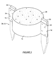
- FIGURE 2 is a perspective view of a preferred embodiment of a concrete forming tube 12 used in accordance with the present invention as a concrete footing pad and which is indicated generally at 28.
- Stakes 30 are driven into the ground just outside the circumference of the proposed circular pad 28.
- the desired length of fabric tube 42 is cut with a utility knife 52 from the longer length 40, and the longitudinal tabs 16 are stapled 34 to each stake 30 to support the tube in the correct position.
- Larger diameter pads could have a multiplicity of longitudinal tabs and supporting stakes. Pads could range in diameter from 450 mm up to 3000 mm, with the fabric tube welded or sewn together to achieve these diameters.
- Concrete 26 is placed inside the tube, and trowelled flat to the top of the fabric tube 12.
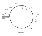
- FIGURE 3 is a cross section of the fabric tube 12 expanded as if by the concrete to show manufacturing details.
- Three flexible sheet form elements 14 of indefinite length and a specific width are welded or sewn together at points 36 to form the correct diameter for the column or pad. Welding is the preferable method of joining as sewing can weaken the joint and create small holes for the concrete to leak out.
- the longitudinal tabs run the full length of the tube, with a width 38 running past the joining width 36. This longitudinal tab is sandwiched between the two vertical support members 18, 20 to support the tube in the vertical position for proper location during the concrete pour.
- the width of the longitudinal tab 38 is usually the same as the width of the vertical support members 18, 20 to ensure proper positioning of the tab.
- the manufacturing process must accurately align and weld the fabric so that the correct diameter of the inflated tube is achieved. As the diameter of the tube increases, the hoop tension of the fabric will increase because of the increased concrete pressure. Therefore the thickness of the fabric and the width of the welded or sewn joint must be correspondingly increased.
- a zipper 44 is shown in FIGURE 3 .
- the zipper would be used where it is desirable to recycle the tube form to lower forming costs.
- the zipper would also have applications where it is needed to place a concrete column around an existing steel column, for example to protect a steel column in a warehouse from damage.
- the fabric overlap 46 protects the zipper from concrete damage when filling with concrete.
- the zipper would be either welded or sewn to the fabric.
- Velcro or sticky tape 48 may be required to ensure the overlap stays flat when filling to protect the zipper from concrete damage.
- the flexible sheet form element 14 is typically made from a woven polyethylene or polypropylene material, with about 12 tapes per inch in the warp and weft direction.
- the tapes are high density to achieve strength, and a low-density coating on either or both sides of the scrim could be added to ensure the concrete does not leak through the fabric. It would also be possible to increase the fabric strength by adding warp and weft elements made of carbon fiber, for example, which, when left in place would provide external reinforcing to the concrete.
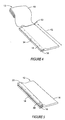
- FIGURE 4 is an isometric view showing the fabric tube 12 being cut to the length 42 of a desired column 10, and the longitudinal tab 16 being positioned and stapled 34 to the first vertical support member 18.
- the tube shape and fabric thickness would only allow the tube to be wound on very large diameter rolls as otherwise the fabric will wrinkle excessively. Therefore packaging of the tube would be on very large rolls and folded, or festooned 40.
- FIGURE 5 is an isometric view showing the second vertical support member 20 being attached to the first member 18 using nails or screws 50.
- the two vertical support members provide support to the longitudinal tab and therefore to the fabric tube during the pouring of concrete.
Landscapes
- Engineering & Computer Science (AREA)
- Architecture (AREA)
- Mechanical Engineering (AREA)
- Civil Engineering (AREA)
- Structural Engineering (AREA)
- Forms Removed On Construction Sites Or Auxiliary Members Thereof (AREA)
- On-Site Construction Work That Accompanies The Preparation And Application Of Concrete (AREA)
- Bridges Or Land Bridges (AREA)
Claims (13)
- Vorgefertigtes, flexibles Schalungsrohr (12) für eine Betonsäule (26) oder ein Betonauflager (26), enthaltend: wenigstens ein flexibles Folienelement (14) einer festgelegten Breite, dadurch gekennzeichnet, dass das flexible Folienelement aus einem Gewebe gefertigt ist und eine Längskante des flexiblen Folienelementes (14) überlappend angeordnet ist mit entweder:i) einer gegenüberliegenden Längskante desselben flexiblen Folienelementes (14), wobei eine Außenoberfläche des flexiblen Folienelementes (14), die einer der Längskanten benachbart ist, an einer Innenoberfläche des flexiblen Folienelementes (14) befestigt ist, um eine Verbindung (36) zu bilden und so das flexible Schalungsrohr (12) zu erzeugen, und ein Längslappen (16) aus dem flexiblen Folienelement (14) zwischen der anderen der Längskanten und der Verbindung (36) ausgebildet ist; oderii) einer Längskante eines weiteren flexiblen Folienelementes (14), wobei eine Außenoberfläche benachbart der Längskante eines der flexiblen Folienelemente (14) an einer Innenoberfläche des anderen der flexiblen Folienelemente (14) fixiert ist, um eine Verbindung (36) zu bilden, und ein Längslappen (16) aus dem anderen flexiblen Folienelement (14) zwischen der Verbindung (36) und der Längskante des anderen flexiblen Folienelementes (14) derart ausgebildet ist, dass die verbundenen flexiblen Folienelemente (14) wenigstens einen Abschnitt des flexiblen Schalungsrohres (12) erzeugen, so dass die Vielzahl verbundener Schalungselemente aus einer flexiblen Folie ein Rohr eines festgelegten Durchmessers mit einer Vielzahl von Längslappen bildet.
- Vorgefertigtes, flexibles Schalungsrohr (12) nach Anspruch 1, bei dem das Rohr (12) aus einer Vielzahl der flexiblen Folienelemente (14) ausgebildet ist, wobei benachbarte flexible Folienelemente (14) der Vielzahl miteinander verbunden sind, wie es in Anspruch 1 beansprucht ist, um wenigstens zwei Verbindungen (36) zu bilden, wobei jede Verbindung (36) einen zugehörigen Längslappen (16) hat.
- Vorgefertigtes, flexibles Schalungsrohr (12) nach Anspruch 1 oder 2, bei dem wenigstens zwei der flexiblen Folienelemente (14) in der Längsrichtung mit Hilfe einer temporären Verbindungseinrichtung (44) verbunden sind.
- Vorgefertigtes, flexibles Schalungsrohr (12) nach Anspruch 3, bei dem die temporäre Verbindungseinrichtung ein Reißverschluss ist.
- Vorgefertigtes, flexibles Schalungsrohr (12) nach Anspruch 1 oder 2, bei dem das Gewebe derart beschaffen ist, dass es an einer Betonsäule oder einem Betonauflager haftet, das ausgebildet wird, indem dem Schalungsrohr Fundamentmaterial (26) zugeführt wird, und das Gewebe von der Betonsäule oder dem Betonauflager nicht abgezogen werden kann.
- Vorgefertigtes, flexibles Schalungsrohr (12) nach Anspruch 5, bei dem das Gewebe Kett- und/oder Durchschusselemente enthält, um die strukturelle Festigkeit der Betonsäule oder des Betonauflagers (26) zu erhöhen.
- Vorgefertigtes, flexibles Schalungsrohr (12) nach Anspruch 6, bei dem die Kett-und/oder Durchschusselemente aus Kohlefasern bestehen.
- Verfahren zum Errichten einer Betonsäule (26), umfassend folgende Schritte:1) Ausbilden eines vorgefertigten, flexiblen Schalungsrohrs (12) für die Betonsäule (26), gekennzeichnet durch folgende Schritte:a) Bereitstellen wenigstens eines flexiblen Folienelementes (14) einer unbestimmten Länge und einer festgelegten Breite, das aus einem Gewebe besteht, wobei das flexible Folienelement (14) eine Längskante hat;b) Anordnen der Längskante in überlappender Beziehung entweder mit:i) einer gegenüberliegenden Längskante desselben flexiblen Folienelementes (14); wobei eine Außenoberfläche des flexiblen Folienelementes (14), benachbart einer der Längskanten, an einer Innenoberfläche des flexiblen Folienelementes (14) fixiert wird, um eine Verbindung (36) auszubilden und dadurch das flexible Schalungsrohr (12) zu erzeugen, das eine unbestimmte Länge und einen speziellen Durchmesser hat; wobei das flexible Schalungsrohr (12) einen Längslappen (16), der aus dem flexiblen Folienelement (14) ausgebildet ist, zwischen der anderen Längskante und der Verbindung (36) aufweist; oderii) einer Längskante eines weiteren flexiblen Folienelementes (14); wobei eine Außenoberfläche eines der flexiblen Folienelemente (14), benachbart zu einer Längskante des flexiblen Folienelementes (14) an einer Innenoberfläche des anderen flexiblen Folienelementes (14) fixiert wird, um eine Verbindung auszubilden und dadurch wenigstens einen Abschnitt eines flexiblen Schalungsrohres (12) einer unbestimmten Länge auszubilden, wobei der wenigstens eine Abschnitt des flexiblen Schalungsrohres (12) einen Längslappen, der aus dem anderen flexiblen Folienelement (14) ausgebildet ist, zwischen der Verbindung (36) und der Längskante des anderen flexiblen Folienelementes (14) aufweist; so dass die Vielzahl der verbundenen Schalungselemente aus flexibler Folie ein Rohr mit einem bestimmten Durchmesser mit einer Vielzahl von Längslappen ausbildet;
wobei das Verfahren weiterhin folgende Schritte umfasst:2) Abschneiden einer bestimmten Länge von dem vorgefertigten, flexiblen Schalungsrohr (12), wobei diese festgelegte Länge gleich der gewünschten Höhe der Betonsäule (26) ist;3) sandwichartiges Anordnen des Längslappens (16) zwischen zwei vertikalen Trägerelementen (18, 20);4) Positionieren und Stützen der vertikalen Trägerelemente (18, 20) mit Stützelementen (22, 30), so dass sich das flexible Schalungsrohr (12) an einer Stelle befindet, an der die Betonsäule (26) zu errichten ist; und5) Zuführen eines flüssigen und aushärtenden Fundamentmaterials (26), um im wesentlichen den Raum innerhalb des flexiblen Schalungsrohres (12) zu füllen, um die Betonsäule (26) auszubilden. - Verfahren zum Errichten einer Betonsäule (26) nach Anspruch 8, bei dem:1) der Schritt des Ausbildens des vorgefertigten, flexiblen Schalungsrohrs (12) das Verbinden einer Vielzahl der flexiblen Folienelemente (14) umfasst, wobei benachbarte flexible Folienelemente (14) aus der Vielzahl miteinander verbunden werden, wie es in Anspruch 8 beansprucht ist, um wenigstens zwei Verbindungen (36) auszubilden, wobei jede Verbindung einen zugeordneten Längslappen (16) hat;2) der Schritt des sandwichartigen Anordnens des Längslappens (16) das sandwichartige Anordnen jedes Längslappens zwischen Paaren vertikaler Trägerelemente umfasst und3) der Schritt des Positionierens und Abstützens das Positionieren und Abstützen jedes Paares vertikaler Trägerelemente (18, 20) mit Abstützelementen (22, 30) umfasst.
- Verfahren zum Errichten einer Betonsäule (26) nach Anspruch 8 oder 9, bei dem das flexible Schalungsrohr (12) die Betonsäule umgebend an Ort und Stelle belassen wird.
- Verfahren zum Errichten eines Betonauflagers (26), umfassend folgende Schritte:1) Ausbilden eines vorgefertigten, flexiblen Schalungsrohrs (12) für das Betonauflager (26), gekennzeichnet durch folgende Schritte:a) Bereitstellen wenigstens eines flexiblen Folienelementes (14) einer unbestimmten Länge und einer festgelegten Breite, das aus einem Gewebe besteht, wobei das flexible Folienelement (14) eine Längskante hat;b) Anordnen der Längskante in überlappender Art und Weise entweder mit:i) einer gegenüberliegenden Längskante desselben flexiblen Folienelementes (14); wobei eine Außenoberfläche des flexiblen Folienelementes (14), benachbart zu einer der Längskanten, an einer Innenoberfläche des flexiblen Folienelementes (14) fixiert wird, um eine Verbindung (36) auszubilden und dadurch das flexible Schalungsrohr (12) auszubilden, das eine unbestimmte Länge und einen bestimmten Durchmesser hat; wobei das flexible Schalungsrohr (12) einen Längslappen (16), der aus dem flexiblen Folienelement (14) ausgebildet ist, zwischen der anderen der Längskanten und der Verbindung (36) aufweist; oderii) einer Längskante eines weiteren flexiblen Folienelementes (14);
wobei eine Außenoberfläche eines der flexiblen Folienelemente (14), benachbart zu einer Längskante des flexiblen Folienelementes (14), an einer Innenoberfläche des anderen flexiblen Folienelementes (14) fixiert wird, um eine Verbindung (36) auszubilden und dadurch wenigstens einen Abschnitt des flexiblen Schalungsrohrs (12) unbestimmter Länge auszubilden, wobei der wenigstens eine Abschnitt des flexiblen Schalungsrohres (12) einen Längslappen (16), der aus dem anderen flexiblen Folienelemente (14) ausgebildet ist, zwischen der Verbindung (36) und der Längskante des anderen flexiblen Folienelementes (14) aufweist, so dass die Vielzahl der verbundenen Schalungselemente aus flexibler Folie ein Rohr eines bestimmten Durchmessers mit einer Vielzahl von Längslappen bildet;
wobei das Verfahren weiterhin folgende Schritte umfasst:2) Abschneiden einer bestimmten Länge des vorgefertigten, flexiblen Schalungsrohrs (12), wobei die bestimmte Länge gleich der gewünschten Höhe des Betonauflagers (26) ist;3) Positionieren eines Pflocks (30) im Bereich einer gewünschten Stelle für das Betonauflager (26);4) Anbringen (34) des Längslappens (16) an dem Pflock (30), um das flexible Schalungsrohr (12) an der gewünschten Stelle zu positionieren; und5) Zuführen eines flüssigen und aushärtenden Fundamentmaterials (26), um im wesentlichen den Raum innerhalb des flexiblen Schalungsrohrs (12) zu füllen und das Betonauflager (26) auszubilden. - Verfahren zum Errichten eines Betonauflagers (26) nach Anspruch 11, bei dem:1) der Schritt des Ausbildens des vorgefertigten, flexiblen Schalungsrohrs (12) das Verbinden einer Vielzahl der flexiblen Folienelementes (14) umfasst, wobei benachbarte flexible Folienelemente (14) aus der Vielzahl miteinander verbunden werden, wie es in Anspruch 11 beansprucht ist, um wenigstens zwei Verbindungen (36) auszubilden, wobei jede Verbindung einen zugeordneten Längslappen (16) hat;2) der Schritt des Positionierens des Pflocks das Positionieren eines Pflocks (30) für jeden Längslappen (16) im Bereich der gewünschten Stelle beinhaltet, wobei der Abstand zwischen benachbarten Pflöcken gleich dem Abstand wischen benachbarten Längslappen (16) ist; und3) der Anbringungsschritt das Anbringen jedes Längslappens (16) an einem entsprechenden Pfosten (30) umfasst.
- Verfahren zum Errichten eines Betonauflagers (26) nach Anspruch 10, bei dem das flexible Schalungsrohr (12) das Betonauflager (26) umgebend an Ort und Stelle belassen wird.
Applications Claiming Priority (3)
| Application Number | Priority Date | Filing Date | Title |
|---|---|---|---|
| US42002902P | 2002-10-22 | 2002-10-22 | |
| US420029P | 2002-10-22 | ||
| PCT/IB2003/004633 WO2004038127A1 (en) | 2002-10-22 | 2003-10-22 | Fabric column and pad concrete form |
Publications (2)
| Publication Number | Publication Date |
|---|---|
| EP1567735A1 EP1567735A1 (de) | 2005-08-31 |
| EP1567735B1 true EP1567735B1 (de) | 2012-06-06 |
Family
ID=32176503
Family Applications (1)
| Application Number | Title | Priority Date | Filing Date |
|---|---|---|---|
| EP03758384A Expired - Lifetime EP1567735B1 (de) | 2002-10-22 | 2003-10-22 | Textilschalung für eine säule oder einen sockel |
Country Status (7)
| Country | Link |
|---|---|
| US (2) | US20040128922A1 (de) |
| EP (1) | EP1567735B1 (de) |
| JP (1) | JP2006504009A (de) |
| AU (1) | AU2003274402A1 (de) |
| BR (1) | BR0315526A (de) |
| MX (1) | MXPA05004260A (de) |
| WO (1) | WO2004038127A1 (de) |
Cited By (1)
| Publication number | Priority date | Publication date | Assignee | Title |
|---|---|---|---|---|
| CN110306727A (zh) * | 2019-06-10 | 2019-10-08 | 山东科技大学 | 预制预应力钢管混凝土柱及施工方法 |
Families Citing this family (8)
| Publication number | Priority date | Publication date | Assignee | Title |
|---|---|---|---|---|
| ES2297971B1 (es) * | 2005-05-24 | 2009-08-24 | Jesus Sanchez Reñasco | Encofrado para columnas cilindricas. |
| US8286398B2 (en) * | 2008-07-15 | 2012-10-16 | Richard Fearn | Monopour form |
| NO336311B1 (no) * | 2010-03-12 | 2015-07-27 | Mindor As | Søyleforskaling. |
| US9097017B1 (en) * | 2012-11-04 | 2015-08-04 | Hector Vanlennep | Easy fit concealed post anchor system |
| CA2940801C (en) * | 2016-05-09 | 2023-08-29 | Gaetan Genest | Foundation for the support of a structure and method of installation |
| KR20190057078A (ko) * | 2016-09-14 | 2019-05-27 | 아마트론 시스템즈, 엘엘씨 | 고속 압출 프린팅에 의한 보강 시멘트질 건설 방법 및 이를 이용하는 장치 |
| US9915064B1 (en) * | 2016-11-11 | 2018-03-13 | Mark E. Sanders | Method and apparatus for reducing propagation of cracks in concrete |
| JP7224258B2 (ja) * | 2019-08-19 | 2023-02-17 | 鹿島建設株式会社 | プレファブ部材 |
Family Cites Families (15)
| Publication number | Priority date | Publication date | Assignee | Title |
|---|---|---|---|---|
| US821738A (en) * | 1905-12-02 | 1906-05-29 | Leverett A Pratt | Mold for concrete posts. |
| US1510950A (en) * | 1919-11-15 | 1924-10-07 | Charles M Markham | Round column clamp |
| US2505426A (en) * | 1948-12-18 | 1950-04-25 | O'flaherty Michael | Method of molding concrete structures by means of collapsible tubular forms |
| US4790509A (en) * | 1987-05-19 | 1988-12-13 | Cardwell William L | Tubular concrete form collar |
| US4854542A (en) * | 1988-10-03 | 1989-08-08 | Pruett M B | Concrete column form |
| SE9101464D0 (sv) * | 1991-05-15 | 1991-05-15 | Lars Fredrik Forsbaeck | Anordning foer eliminering av moebelhaelta |
| US5368269A (en) * | 1992-07-14 | 1994-11-29 | Alpha Forming Systems, Division Of Elco Concrete Co, Inc | Adjustable bracing system for column forms |
| US5328142A (en) * | 1992-07-17 | 1994-07-12 | Sonoco Products Company | Concrete column forming tube |
| SE506023C2 (sv) * | 1992-10-09 | 1997-11-03 | Anders Mohss | Fristående vertikal gjutform för exempelvis plintar och pelare |
| JP3192277B2 (ja) * | 1993-05-14 | 2001-07-23 | 新日本製鐵株式会社 | コンクリート柱 |
| US5580480A (en) * | 1994-01-03 | 1996-12-03 | Chatelain; Paul J. | Form for making fence posts in situ |
| US5794387A (en) * | 1997-03-20 | 1998-08-18 | Musco Corporation | Device and method to lift and manipulate poles which are mounted onto a base |
| FR2789706B1 (fr) * | 1999-02-15 | 2001-04-13 | Waterair Ind | Procede d'etanconnement a l'aide de piliers de renfort d'une structure a parois verticales et pilier a cet effet |
| US6832454B1 (en) * | 1999-07-28 | 2004-12-21 | South Dakota School Of Mines And Technology | Beam filled with material, deck system and method |
| JP3484156B2 (ja) * | 1999-12-27 | 2004-01-06 | 構造品質保証研究所株式会社 | 構築物の補強方法及びその構造 |
-
2003
- 2003-10-22 MX MXPA05004260A patent/MXPA05004260A/es not_active Application Discontinuation
- 2003-10-22 WO PCT/IB2003/004633 patent/WO2004038127A1/en not_active Ceased
- 2003-10-22 BR BR0315526-9A patent/BR0315526A/pt not_active Application Discontinuation
- 2003-10-22 AU AU2003274402A patent/AU2003274402A1/en not_active Abandoned
- 2003-10-22 US US10/689,639 patent/US20040128922A1/en not_active Abandoned
- 2003-10-22 EP EP03758384A patent/EP1567735B1/de not_active Expired - Lifetime
- 2003-10-22 JP JP2004546281A patent/JP2006504009A/ja active Pending
-
2007
- 2007-11-03 US US11/982,617 patent/US20080083190A1/en not_active Abandoned
Cited By (1)
| Publication number | Priority date | Publication date | Assignee | Title |
|---|---|---|---|---|
| CN110306727A (zh) * | 2019-06-10 | 2019-10-08 | 山东科技大学 | 预制预应力钢管混凝土柱及施工方法 |
Also Published As
| Publication number | Publication date |
|---|---|
| AU2003274402A1 (en) | 2004-05-13 |
| WO2004038127A1 (en) | 2004-05-06 |
| EP1567735A1 (de) | 2005-08-31 |
| BR0315526A (pt) | 2005-08-23 |
| US20080083190A1 (en) | 2008-04-10 |
| JP2006504009A (ja) | 2006-02-02 |
| US20040128922A1 (en) | 2004-07-08 |
| MXPA05004260A (es) | 2005-07-05 |
Similar Documents
| Publication | Publication Date | Title |
|---|---|---|
| US20080083190A1 (en) | Fabric column and pad concrete form | |
| US5328142A (en) | Concrete column forming tube | |
| US5495810A (en) | Corrugated cardboard tube and pallet using the same | |
| US7874540B2 (en) | Concrete form for pouring non-round columns, and method of making same | |
| US8313080B2 (en) | Retaining device for assembling two panels, recyclable formwork for forming a concrete structure and packaging assembly using the same | |
| US20050066592A1 (en) | Forming apparatus and method for constructing concrete columns | |
| EP0192308B1 (de) | Behälter zum Aufstellen an einer festen Stelle auf dem Boden und Verfahren zur Herstellung des Behälters | |
| KR20190063645A (ko) | 폐단면 합성 기둥과 철골보 연결 구조 및 이의 시공 방법 | |
| WO1993014287A1 (en) | Form for casting building elements | |
| US3980268A (en) | Circular column mold having an upper alignment ring | |
| CA2916214A1 (en) | Modular void form | |
| CA2505683A1 (en) | Fabric column and pad concrete form | |
| AU2021107665B4 (en) | Swimming Pool Construction | |
| US20050070187A1 (en) | Form for containing settable filler material during setting | |
| JP6325380B2 (ja) | コンクリート構造物の補強方法及び補強構造 | |
| JP7008008B2 (ja) | 橋脚構築方法、橋脚 | |
| AU4575002A (en) | Formwork for casting concrete and method for doing same | |
| EP4251808B1 (de) | Zusammenklappbare bauvorrichtung | |
| CN217053463U (zh) | 一种明挖浅埋隧道内埋式格构柱 | |
| KR20160084643A (ko) | 중량물의 기초 받침대 및 그 받침대 시공방법 | |
| JP3308199B2 (ja) | ケーブルドラム | |
| JP6951961B2 (ja) | 地上タンクおよび地上タンクの構築方法 | |
| CN118407344A (zh) | 模块化玻纤套筒及其施工方法 | |
| JPH07252849A (ja) | 建築基礎の施工方法及び型枠板 | |
| CN119711508A (zh) | 可与钢支撑配合的装配式钢混基坑支撑梁段及预制方法 |
Legal Events
| Date | Code | Title | Description |
|---|---|---|---|
| PUAI | Public reference made under article 153(3) epc to a published international application that has entered the european phase |
Free format text: ORIGINAL CODE: 0009012 |
|
| 17P | Request for examination filed |
Effective date: 20050510 |
|
| AK | Designated contracting states |
Kind code of ref document: A1 Designated state(s): AT BE BG CH CY CZ DE DK EE ES FI FR GB GR HU IE IT LI LU MC NL PT RO SE SI SK TR |
|
| AX | Request for extension of the european patent |
Extension state: AL LT LV MK |
|
| DAX | Request for extension of the european patent (deleted) | ||
| GRAP | Despatch of communication of intention to grant a patent |
Free format text: ORIGINAL CODE: EPIDOSNIGR1 |
|
| GRAS | Grant fee paid |
Free format text: ORIGINAL CODE: EPIDOSNIGR3 |
|
| RIN1 | Information on inventor provided before grant (corrected) |
Inventor name: FEARN, RICHARD |
|
| GRAA | (expected) grant |
Free format text: ORIGINAL CODE: 0009210 |
|
| AK | Designated contracting states |
Kind code of ref document: B1 Designated state(s): AT BE BG CH CY CZ DE DK EE ES FI FR GB GR HU IE IT LI LU MC NL PT RO SE SI SK TR |
|
| REG | Reference to a national code |
Ref country code: GB Ref legal event code: FG4D |
|
| REG | Reference to a national code |
Ref country code: CH Ref legal event code: EP Ref country code: AT Ref legal event code: REF Ref document number: 561135 Country of ref document: AT Kind code of ref document: T Effective date: 20120615 |
|
| REG | Reference to a national code |
Ref country code: IE Ref legal event code: FG4D |
|
| REG | Reference to a national code |
Ref country code: DE Ref legal event code: R096 Ref document number: 60341164 Country of ref document: DE Effective date: 20120809 |
|
| REG | Reference to a national code |
Ref country code: NL Ref legal event code: VDEP Effective date: 20120606 |
|
| PG25 | Lapsed in a contracting state [announced via postgrant information from national office to epo] |
Ref country code: SE Free format text: LAPSE BECAUSE OF FAILURE TO SUBMIT A TRANSLATION OF THE DESCRIPTION OR TO PAY THE FEE WITHIN THE PRESCRIBED TIME-LIMIT Effective date: 20120606 Ref country code: CY Free format text: LAPSE BECAUSE OF FAILURE TO SUBMIT A TRANSLATION OF THE DESCRIPTION OR TO PAY THE FEE WITHIN THE PRESCRIBED TIME-LIMIT Effective date: 20120606 Ref country code: FI Free format text: LAPSE BECAUSE OF FAILURE TO SUBMIT A TRANSLATION OF THE DESCRIPTION OR TO PAY THE FEE WITHIN THE PRESCRIBED TIME-LIMIT Effective date: 20120606 |
|
| REG | Reference to a national code |
Ref country code: AT Ref legal event code: MK05 Ref document number: 561135 Country of ref document: AT Kind code of ref document: T Effective date: 20120606 |
|
| PG25 | Lapsed in a contracting state [announced via postgrant information from national office to epo] |
Ref country code: GR Free format text: LAPSE BECAUSE OF FAILURE TO SUBMIT A TRANSLATION OF THE DESCRIPTION OR TO PAY THE FEE WITHIN THE PRESCRIBED TIME-LIMIT Effective date: 20120907 Ref country code: SI Free format text: LAPSE BECAUSE OF FAILURE TO SUBMIT A TRANSLATION OF THE DESCRIPTION OR TO PAY THE FEE WITHIN THE PRESCRIBED TIME-LIMIT Effective date: 20120606 |
|
| PG25 | Lapsed in a contracting state [announced via postgrant information from national office to epo] |
Ref country code: EE Free format text: LAPSE BECAUSE OF FAILURE TO SUBMIT A TRANSLATION OF THE DESCRIPTION OR TO PAY THE FEE WITHIN THE PRESCRIBED TIME-LIMIT Effective date: 20120606 Ref country code: RO Free format text: LAPSE BECAUSE OF FAILURE TO SUBMIT A TRANSLATION OF THE DESCRIPTION OR TO PAY THE FEE WITHIN THE PRESCRIBED TIME-LIMIT Effective date: 20120606 Ref country code: CZ Free format text: LAPSE BECAUSE OF FAILURE TO SUBMIT A TRANSLATION OF THE DESCRIPTION OR TO PAY THE FEE WITHIN THE PRESCRIBED TIME-LIMIT Effective date: 20120606 Ref country code: BE Free format text: LAPSE BECAUSE OF FAILURE TO SUBMIT A TRANSLATION OF THE DESCRIPTION OR TO PAY THE FEE WITHIN THE PRESCRIBED TIME-LIMIT Effective date: 20120606 Ref country code: AT Free format text: LAPSE BECAUSE OF FAILURE TO SUBMIT A TRANSLATION OF THE DESCRIPTION OR TO PAY THE FEE WITHIN THE PRESCRIBED TIME-LIMIT Effective date: 20120606 Ref country code: NL Free format text: LAPSE BECAUSE OF FAILURE TO SUBMIT A TRANSLATION OF THE DESCRIPTION OR TO PAY THE FEE WITHIN THE PRESCRIBED TIME-LIMIT Effective date: 20120606 Ref country code: SK Free format text: LAPSE BECAUSE OF FAILURE TO SUBMIT A TRANSLATION OF THE DESCRIPTION OR TO PAY THE FEE WITHIN THE PRESCRIBED TIME-LIMIT Effective date: 20120606 |
|
| PG25 | Lapsed in a contracting state [announced via postgrant information from national office to epo] |
Ref country code: PT Free format text: LAPSE BECAUSE OF FAILURE TO SUBMIT A TRANSLATION OF THE DESCRIPTION OR TO PAY THE FEE WITHIN THE PRESCRIBED TIME-LIMIT Effective date: 20121008 Ref country code: IT Free format text: LAPSE BECAUSE OF FAILURE TO SUBMIT A TRANSLATION OF THE DESCRIPTION OR TO PAY THE FEE WITHIN THE PRESCRIBED TIME-LIMIT Effective date: 20120606 |
|
| PGFP | Annual fee paid to national office [announced via postgrant information from national office to epo] |
Ref country code: GB Payment date: 20121018 Year of fee payment: 10 |
|
| PLBE | No opposition filed within time limit |
Free format text: ORIGINAL CODE: 0009261 |
|
| STAA | Information on the status of an ep patent application or granted ep patent |
Free format text: STATUS: NO OPPOSITION FILED WITHIN TIME LIMIT |
|
| PG25 | Lapsed in a contracting state [announced via postgrant information from national office to epo] |
Ref country code: DK Free format text: LAPSE BECAUSE OF FAILURE TO SUBMIT A TRANSLATION OF THE DESCRIPTION OR TO PAY THE FEE WITHIN THE PRESCRIBED TIME-LIMIT Effective date: 20120606 Ref country code: ES Free format text: LAPSE BECAUSE OF FAILURE TO SUBMIT A TRANSLATION OF THE DESCRIPTION OR TO PAY THE FEE WITHIN THE PRESCRIBED TIME-LIMIT Effective date: 20120917 |
|
| 26N | No opposition filed |
Effective date: 20130307 |
|
| PG25 | Lapsed in a contracting state [announced via postgrant information from national office to epo] |
Ref country code: MC Free format text: LAPSE BECAUSE OF NON-PAYMENT OF DUE FEES Effective date: 20121031 |
|
| REG | Reference to a national code |
Ref country code: CH Ref legal event code: PL |
|
| REG | Reference to a national code |
Ref country code: DE Ref legal event code: R084 Ref document number: 60341164 Country of ref document: DE Effective date: 20130429 |
|
| REG | Reference to a national code |
Ref country code: DE Ref legal event code: R097 Ref document number: 60341164 Country of ref document: DE Effective date: 20130307 |
|
| REG | Reference to a national code |
Ref country code: IE Ref legal event code: MM4A |
|
| REG | Reference to a national code |
Ref country code: FR Ref legal event code: ST Effective date: 20130628 |
|
| PG25 | Lapsed in a contracting state [announced via postgrant information from national office to epo] |
Ref country code: LI Free format text: LAPSE BECAUSE OF NON-PAYMENT OF DUE FEES Effective date: 20121031 Ref country code: IE Free format text: LAPSE BECAUSE OF NON-PAYMENT OF DUE FEES Effective date: 20121022 Ref country code: CH Free format text: LAPSE BECAUSE OF NON-PAYMENT OF DUE FEES Effective date: 20121031 Ref country code: BG Free format text: LAPSE BECAUSE OF FAILURE TO SUBMIT A TRANSLATION OF THE DESCRIPTION OR TO PAY THE FEE WITHIN THE PRESCRIBED TIME-LIMIT Effective date: 20120906 |
|
| PGFP | Annual fee paid to national office [announced via postgrant information from national office to epo] |
Ref country code: DE Payment date: 20130423 Year of fee payment: 10 |
|
| PG25 | Lapsed in a contracting state [announced via postgrant information from national office to epo] |
Ref country code: FR Free format text: LAPSE BECAUSE OF NON-PAYMENT OF DUE FEES Effective date: 20121031 |
|
| PG25 | Lapsed in a contracting state [announced via postgrant information from national office to epo] |
Ref country code: TR Free format text: LAPSE BECAUSE OF FAILURE TO SUBMIT A TRANSLATION OF THE DESCRIPTION OR TO PAY THE FEE WITHIN THE PRESCRIBED TIME-LIMIT Effective date: 20120606 |
|
| PG25 | Lapsed in a contracting state [announced via postgrant information from national office to epo] |
Ref country code: LU Free format text: LAPSE BECAUSE OF NON-PAYMENT OF DUE FEES Effective date: 20121022 |
|
| GBPC | Gb: european patent ceased through non-payment of renewal fee |
Effective date: 20131022 |
|
| PG25 | Lapsed in a contracting state [announced via postgrant information from national office to epo] |
Ref country code: GB Free format text: LAPSE BECAUSE OF NON-PAYMENT OF DUE FEES Effective date: 20131022 Ref country code: HU Free format text: LAPSE BECAUSE OF FAILURE TO SUBMIT A TRANSLATION OF THE DESCRIPTION OR TO PAY THE FEE WITHIN THE PRESCRIBED TIME-LIMIT Effective date: 20031022 |
|
| REG | Reference to a national code |
Ref country code: DE Ref legal event code: R119 Ref document number: 60341164 Country of ref document: DE Effective date: 20140501 |
|
| PG25 | Lapsed in a contracting state [announced via postgrant information from national office to epo] |
Ref country code: DE Free format text: LAPSE BECAUSE OF NON-PAYMENT OF DUE FEES Effective date: 20140501 |