EP1567720B1 - Dispositif de levage de lames destine a deplacer des lames d'aiguilles - Google Patents
Dispositif de levage de lames destine a deplacer des lames d'aiguilles Download PDFInfo
- Publication number
- EP1567720B1 EP1567720B1 EP03776887A EP03776887A EP1567720B1 EP 1567720 B1 EP1567720 B1 EP 1567720B1 EP 03776887 A EP03776887 A EP 03776887A EP 03776887 A EP03776887 A EP 03776887A EP 1567720 B1 EP1567720 B1 EP 1567720B1
- Authority
- EP
- European Patent Office
- Prior art keywords
- lifting device
- switch blade
- adjusting
- blade lifting
- previous
- Prior art date
- Legal status (The legal status is an assumption and is not a legal conclusion. Google has not performed a legal analysis and makes no representation as to the accuracy of the status listed.)
- Expired - Lifetime
Links
- 238000006073 displacement reaction Methods 0.000 claims abstract description 7
- 230000000295 complement effect Effects 0.000 claims description 4
- 238000013016 damping Methods 0.000 claims description 4
- 230000001174 ascending effect Effects 0.000 claims description 2
- 238000000034 method Methods 0.000 claims description 2
- 230000010355 oscillation Effects 0.000 claims 1
- 210000002105 tongue Anatomy 0.000 description 47
- 230000015572 biosynthetic process Effects 0.000 description 1
- 230000007423 decrease Effects 0.000 description 1
- 230000000694 effects Effects 0.000 description 1
- 238000009434 installation Methods 0.000 description 1
- 230000002035 prolonged effect Effects 0.000 description 1
- 238000005096 rolling process Methods 0.000 description 1
Images





Classifications
-
- E—FIXED CONSTRUCTIONS
- E01—CONSTRUCTION OF ROADS, RAILWAYS, OR BRIDGES
- E01B—PERMANENT WAY; PERMANENT-WAY TOOLS; MACHINES FOR MAKING RAILWAYS OF ALL KINDS
- E01B7/00—Switches; Crossings
- E01B7/02—Tongues; Associated constructions
-
- E—FIXED CONSTRUCTIONS
- E01—CONSTRUCTION OF ROADS, RAILWAYS, OR BRIDGES
- E01B—PERMANENT WAY; PERMANENT-WAY TOOLS; MACHINES FOR MAKING RAILWAYS OF ALL KINDS
- E01B2202/00—Characteristics of moving parts of rail systems, e.g. switches, special frogs, tongues
- E01B2202/04—Nature of the support or bearing
- E01B2202/044—Rolling
- E01B2202/046—Rolling with rolls on fixed part
Definitions
- the invention relates to a tongue lifting device with the preamble features of claim 1 or 2.
- a tongue lifting device for adjusting switch points with a bearing block for attaching the tongue lifting device to a stock rail and at least one roller carriage for supporting at least one roller is known, wherein the switch blade rests at least when adjusting on a roller known tongue lifting device hangs the roller carriage with a bolt and a nut on the bearing block.
- the height adjustment is realized in the known tongue lifting device by hanging from the roller carriage via a bolt-nut arrangement.
- EP 0 674 049 B1 discloses a tongue lifting device with rollers arranged in a downwardly free chamber for carrying the tongue of a switch, wherein the tongue lifting device is adjustable in height and arranged in the threshold field and the rail base of the stock rail is attached to it under cross-cutting.
- the known tongue lifting device is fixed by means of a clamping device firmly on the rail foot of the stock rail.
- the axes of the rollers are jointly on both sides in each case a height-adjustable guide piece, which is used in upwardly open lateral pockets of the roller housing and connected thereto.
- tuning inserts may be inserted between the bottom surface of the pockets and the guide pieces.
- the altitude of the switch blade can be adjusted relative to the rail head of the stock rail.
- the guide piece must be removed together with the rollers. This is laborious and leads to higher costs in adjusting the altitude of the switch blade relative to the rail head of the stock rail.
- Object of the present invention is to provide a tongue lifting device of the type mentioned, in which the height adjustment of the role and thus the adjustment of the altitude of the switch blade relative to the rail head of the stock rail is simple and low labor and cost feasible.
- a tongue lifting device of the type mentioned in the present invention that at least two mutually rotatable adjusting discs are rotatably arranged one above the other on the bearing block that rotation of the adjusting discs relative to each other causes a height adjustment of the roller carriage.
- the invention offers the significant advantage that it is no longer necessary to expand the roller carriage for height adjustment of the roller carriage or for height adjustment of the switch blade during the adjustment.
- the height adjustment of the roller carriage is effected by the rotation of at least one adjusting disc. This makes it possible in a simple manner to compensate for tolerances in both the switch blade and in the stock rail and adapt the tongue lift to different cheek rail cross sections.
- the tongue lifting device according to the invention is characterized in that the rotation of the adjusting disc only a small force: must be expended, whereby the height adjustment of the roller carriage is additionally facilitated.
- At least two mutually adjustable adjusting discs are arranged one above the other, that an adjustment of the adjusting discs causes a height adjustment of the roller carriage.
- the mutually adjustable adjusting disks act together, wherein in the installed state of the tongue lifting device preferably faces the adjusting discs each other, wherein, more preferably, a footprint of at least one stage of a first adjusting disc rests on a footprint of at least one stage of another adjusting disc.
- adjusting the switch blade this is preferably pulled by a motor on the rollers and is in the course of the adjustment on the role. It is so that the weight of the switch blade is introduced via the shelves of mutually facing, mutually adjustable adjusting discs in the bearing block.
- a first adjusting disc preferably serves as an abutment for the second of the two mutually adjustable adjusting discs.
- the adjusting disc has a wedge-shaped thickness profile and / or a step-shaped thickness profile with at least two steps with different step heights. Each step corresponds to a fixed height adjustment of the roller carriage.
- a wedge-shaped thickness profile of the adjusting disk can also be provided in order to enable a height adjustment of the roller carriage.
- it is important that the number of stages over which the weight force of the switch blade or roller carriage is introduced into the bearing block is sufficiently large so as not to exceed the limit of the permissible surface pressure.
- the adjusting disk preferably has a plurality of juxtaposed step sequences each having a plurality of steps with different step heights.
- the step heights of adjacent steps of a step sequence are ascending or descending graded, whereby the stepwise raising or lowering of the roller carriage relative to the bearing block with little effort is possible.
- the height difference between two step heights of adjacent steps should be relatively small and preferably in the range of 0.5 to 5 mm, preferably about 1 mm.
- the adjusting disc has identical stages, preferably two or three stages are provided. It is the case here that at least one stage of a first step sequence and at least one further step of at least one further step sequence have the same step height.
- loading case ie in the installed state of the roller carriage at the role of overlying switch blade, therefore, the weight of the roller carriage or the switch blade is distributed to the shelves several stages of a control disc, whereby the surface pressure of each footprint decreases. If the roller carriage is supported on a plurality of shelves, the stability of the bearing of the roller carriage on the bearing block also increases.
- this has at least one engaging portion, wherein the engaging portion is preferably provided in the region of a step with a large step height, for example in the region of the step with the largest step height.
- the engaging portion must be arranged so that it does not come to the material breakage of the adjusting disk when adjusting the adjusting disc.
- the engagement section should therefore be arranged as far as possible in a region of the adjusting disk in which the material thickness of the adjusting disk is particularly large.
- the edges of the stages of a sequence of steps are bevelled relative to the vertical, so that there are chamfers.
- the step with the largest step height should have a non-bevelled edge.
- the non-chamfered edge can serve, for example, as a stop surface for limiting the adjustment of the adjusting disc.
- the adjusting disks each have step sequences and / or steps with step heights, which are complementary to each other at preferably minimal height position of the adjusting disks.
- the shelves of mutually complementary stages of the adjusting discs are superimposed, so that substantially the entire cross-sectional area of the adjusting disc serves as a support surface of the roller carriage.
- the attack sections of the mutually adjustable adjusting discs can preferably come to a stop with minimum height position of the roller carriage.
- the flanks of the steps can come to a stop against each other.
- the stop is preferred with minimum height position of the adjusting discs, it can of course also be provided that the attack sections of the mutually adjustable adjusting disks or the flanks of at least individual stages of the adjusting discs against each other come to a stop at the maximum height position of the adjusting discs.
- the mutually adjustable adjusting discs are identical components that rest on each other in the installed state with their respective shelves.
- the adjusting disc In order to center the mutually adjustable adjusting discs between the roller carriage and the bearing block, the adjusting disc preferably have a central through hole for a centering means, for example for a set screw on.
- the roller carriage is preferably braced by the centering in the bearing block or detected on the bearing block.
- the roller carriage on a recess for receiving the adjusting discs, whereby they are fixed or fixed in the roller carriage.
- the recess of the roller carriage releases an engagement region, preferably in the longitudinal direction of the roller in the roller carriage on the longitudinal side of the roller carriage facing away from the roller.
- the engagement area preferably points into the threshold field.
- the engagement area limits the permissible travel of the mutually adjustable adjusting discs.
- the engagement region can be defined by the distance between two abutment surfaces of the roller carriage, wherein preferably the engaging portion of at least one adjusting disc at minimum or maximum height position of the roller carriage abuts directly on a stop surface of the roller carriage. This can be ensured in a simple manner be that the adjusting disks can be adjusted against each other only within the range defined by the distance between two abutment surfaces.
- the roller carriage is provided for supporting a plurality of rollers, wherein the switch blade preferably rests upon adjustment on a roller plane defined by the rollers.
- a plurality of adjusting disks can be provided in order to incline the roller plane in the direction of the horizontal. This facilitates the rolling of the switch to the roller level.
- An inclination of the roller plane of the rollers can also be effected by the formation of the adjusting disc as such, wherein the adjusting disc preferably has a wedge-shaped cross-sectional shape and / or is arranged obliquely.
- At least one damping means preferably a plastic intermediate layer, for damping vibrations between the roller carriage and the bearing block.
- a damping means preferably a plastic intermediate layer
- the tongue lifting device 1 shows a first embodiment of a tongue lifting device 1 according to the invention for adjusting a switch tongue 2 with a bearing block 3 for fastening the tongue lifting device 1 to a stock rail 4.
- the tongue lifting device 1 has two roller carriages 5 for supporting two rollers 6, wherein the rollers are each mounted on the longitudinal side.
- the switch blade 2 rests on a roller plane provided by the rollers 6.
- the roller carriage 5 are based on two adjusting disks 7, 8, of which the other rests on the bearing block 3.
- the adjusting discs 7, 8 are rotatably mounted on the bearing block 3, that a rotation of the adjusting discs 7, 8 causes a height adjustment of the roller carriage 5 and thus a height adjustment of the rollers 6 and the roller plane.
- the bearing block 3 is clamped in a conventional manner with the stock rail 4 via a known locking device, as this is already known from the aforementioned prior art.
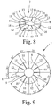
- FIGS. 8 to 11 it can be seen that in the installed state of the tongue lifting device 1 shelves 9, 10, 11, 12 of the superposed adjusting discs 7, 8 face each other. As is apparent from FIGS. 10 and 11, are in the installed state of the tongue lifting device 1, the stages 13, 14, 15, 16 of the adjusting disc 8 with the corresponding shelves on corresponding shelves of the steps 13, 14, 15, 16 of the adjusting disc 7.
- the adjusting disc 7 serves as an abutment for the adjusting disc 8, and vice versa. It is equally well possible in the unclaimed variant that an adjustment range of the roller carriage 5 and / or the bearing block 3 is provided as an abutment for a setting disc 7, 8.
- the adjusting disk 7, 8 preferably has a step-shaped thickness profile with a plurality of steps 13, 14, 15, 16 with different step heights.
- Each stage 13, 14, 15, 16 also has a footprint 9, 10, 11, 12, on which rest in the installed state, the corresponding shelves of the adjustable disc 7 relative to the adjusting disc 8 arranged.
- the step sequences 13, 14, 15, 16 are distributed according to the embodiment of the adjusting disc 7 shown in FIGS. 8 and 9 several times over the circumference of the adjusting disc 7. It is so that the step heights of the steps 13, 14, 15, 16 are stepped next to each other in descending order.
- the adjusting disc 7 also has identical steps, each consisting of the steps 13, 14, 15, 16. In the installed state or in the operating state, it is such that at least three equal shelves 9 or 10 or 11 or 12 of the adjusting disc 7 come to rest with the corresponding shelves 8 of the adjusting disc. As a result, on the one hand, the weight of the switch blade 2 evenly distributed over the adjusting discs 7, 8, on the other hand ensures the stability of the arrangement of the roller carriage 5 on the bearing block 3.
- the step heights of the steps 13 or 14 or 15 or 16 of the adjusting disks 7, 8 are preferably of the same design.
- the adjusting discs 7, 8 may also have a rectangular cross-sectional profile with a wedge-shaped thickness profile, is provided according to FIGS. 1 to 12, that the adjusting discs 7, 8 are circular.
- the steps 13 or 14 or 15 or 16 with the same step height are preferably arranged distributed symmetrically over the circumference of the adjusting disks 7, 8.
- Each adjusting disc 7, 8 has an engaging portion 17, 18 for mutual adjustment of the adjusting discs 7, 8.
- the engagement section 17, 18 is preferably provided in the region of the step 13 with the largest step height in order to prevent material fracture.
- FIG. 8 to 11 further show that the flanks of the steps 13, 14, 15, 16 are beveled from the vertical and form bevels.
- the stage 13 has two flanks, with one flank not bevelled.
- Fig. 11 the arrangement of the adjusting discs 7, 8 is shown at minimum height position of the roller carriage 5.
- the mutually adjustable adjusting disks 7, 8 each have step sequences and / or stages 13, 14, 15, 16 with step heights, which are complementary to each other at preferably minimum height position of the adjusting disks 7, 8.
- With minimal height position of the adjusting discs 7, 8 are therefore all shelves 9, 10, 11, 12 of the stages 13, 14, 15, 16 of the adjusting discs 7, 8 on each other.
- the engagement portions 17, 18 at preferably minimal height position of the adjusting disks 7, 8 against each other to the stop, as it is also shown in Fig. 11. It is preferably such that at minimum height position, the vertical edges of all stages 13 of the adjusting disc 7 with the vertical edges the stages 13 of the adjusting disc 8 come to a stop.
- the attack sections 17, 18 at maximum height position against each other come to a stop and / or that at least one of the other stages 14, 15, 16 also has a vertical edge to an enlarged stop surface to limit the adjustment of the preset against each adjusting pulleys 7, 8 pretend.
- the inclined flanks of the steps 14, 15, 16 of the adjusting disc 7 come at a minimum height position with the flanks of the corresponding stages of the adjusting disc 8 to stop.
- a particularly simple embodiment of the tongue lifting device 1 provides that the adjusting discs 7, 8 are formed as identical components.
- Fig. 1 the tongue lifting device 1 is shown at minimum height position of the roller carriage 5.
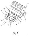
- the adjusting discs 7, 8 come in this operating state with their attack sections 17, 18 against each other to stop. 2, however, the maximum height adjustment of the roller carriage 5 is shown, wherein the adjusting discs 7, 8 are adjusted so far against each other, that the engaging portions 17, 18 come to the roller carriage 5 to the stop.
- Fig. 3 is a side view of the operating state of the tongue lifting device 1 shown in Fig. 2 is shown.
- Clearly visible is a gap between the raised roller carriage 5 and the bearing block 3, resulting from the adjustment of the adjusting discs 7, 8.
- the roller carriage 5 is braced by a centering means, for example by adjusting screws 19, 20, with the bearing block 3.
- the adjusting discs 7, 8 have to perform the screws 19, 20 each have a central through hole, wherein the adjusting discs 7, 8 are centered by the centering. A lateral slippage or an unwanted adjustment of the adjusting discs 7, 8 is prevented.
- FIGS. 5 to 7 a further embodiment of a tongue lifting device 1 according to the invention is shown, wherein the switch blade 2 rests on a roller 6 during adjustment. Otherwise, the embodiment shown in FIGS. 5 to 7 corresponds to the embodiment of a tongue lifting device 1 according to the invention shown in FIGS. 1 to 4.
- a roller carriage 5 which has a recess 21 for receiving the adjusting disc 7, 8.
- the recess 21 has an engagement region 22 which releases the engagement on the engagement section 17, 18 of the adjusting disc 7, 8.
- the engagement region 22 is preferably provided on the longitudinal side of the roller carriage 5 facing away from the roller 6 in order to ensure good access to the engagement sections 17 , 18 of the adjusting discs 7, 8 to allow and thus to carry out the height adjustment of the roller carriage 5 in a simple manner. As can be seen in particular from FIG.
- the engagement region 22 limits the permissible adjustment path of the mutually adjustable adjusting disks 7, 8, whereby it is further preferably provided that the abutment region 22 delimits stop surfaces 23 of the roller carriage 5, wherein at maximum height position of the roller carriage 5 Attack sections 17, 18 of the adjusting discs 7, 8 abut the stop surfaces 23.
- roller carriage 5 is arranged to be adjustable in the longitudinal direction of the stock rail 4 in a conventional manner.
- each roller carriage 5 is arranged on a respective bearing arm 24, 25 of the bearing block 3.
- each bearing arm has a slot 26, through which the centering is guided in the longitudinal direction of the stock rail 4.
- FIGS. 13 and 14 show a further embodiment of a tongue lifting device 1 according to the invention.
- the embodiment shown in FIGS. 13 and 14 has a roller 6 on which the switch blade 2 rests during adjustment.
- two roller carriages 5 are provided, wherein, in contrast to the previously described embodiments of a tongue lifting device 1 according to the invention, the roller 6 is mounted in the roller carriage 5 on the front side.
- the embodiment shown in FIGS. 13 and 14 is characterized by a particularly small installation depth, wherein the bearing block 3 at the location of bearing arms 24, 25 lateral support portions 27, 28, on which the roller carriage 5 via the adjusting discs 7, 8 supported are.
- roller carriage 5 are arranged to be displaceable in the longitudinal direction of the stock rail 4, wherein the roller carriage 5 can be clamped to the bearing block 3 via screws 19, 20.
- the lateral support portions 27, 28 slots 26 To the transverse shift the roller carriage 5, the lateral support portions 27, 28 slots 26.
- the height adjustment of the roller carriage 5 is carried out in the same manner as has already been described with reference to FIGS. 1 to 12.
Landscapes
- Engineering & Computer Science (AREA)
- Mechanical Engineering (AREA)
- Architecture (AREA)
- Civil Engineering (AREA)
- Structural Engineering (AREA)
- Manufacturing Of Tubular Articles Or Embedded Moulded Articles (AREA)
- Load-Engaging Elements For Cranes (AREA)
- Transmission Devices (AREA)
- Processing Of Meat And Fish (AREA)
- Sewing Machines And Sewing (AREA)
- Lift-Guide Devices, And Elevator Ropes And Cables (AREA)
- Agricultural Machines (AREA)
- Tumbler Switches (AREA)
- Forklifts And Lifting Vehicles (AREA)
Claims (27)
- Dispositif de levage de lames (1) destiné à déplacer des lames d'aiguilles (2), avec un sabot d'appui (3) pour la fixation du dispositif de levage de lames (1) sur une contre-aiguille (4) et avec au moins un chariot à galets (5) destiné à supporter au moins un galet (6), dans lequel la lame d'aiguille (2) repose sur le galet (6) au moins lors du déplacement et dans lequel le chariot à galets (5) est supporté sur au moins un disque de réglage (7, 8) reposant sur le sabot d'appui (3), caractérisé en ce qu'au moins deux disques de réglage rotatifs opposés (7, 8) sont disposés de façon rotative l'un au-dessus de l'autre sur le sabot d'appui (3) de telle façon qu'une rotation des disques de réglage (7, 8) l'un par rapport à l'autre provoque un déplacement en hauteur du chariot à galets (5).
- Dispositif de levage de lames (1) destiné à déplacer des lames d'aiguilles (2), avec un sabot d'appui (3) pour la fixation du dispositif de levage de lames (1) sur une contre-aiguille (4) et avec au moins un chariot à galets (5) destiné à supporter au moins un galet (6), dans lequel la lame d'aiguille (2) repose sur le galet (6) au moins lors du déplacement et dans lequel le chariot à galets (5) est supporté sur au moins un disque de réglage (7, 8) reposant sur le sabot d'appui (3), caractérisé en ce qu'au moins deux disques de réglage (7, 8) déplaçables en direction longitudinale vers la contre-aiguille (4) sont disposés de façon déplaçable l'un au-dessus de l'autre sur le sabot d'appui (3) de telle manière qu'un déplacement longitudinal des disques de réglage (7, 8) l'un par rapport à l'autre provoque un déplacement en hauteur du chariot à galets (5).
- Dispositif de levage de lames selon l'une quelconque des revendications précédentes, caractérisé en ce que, lorsque le dispositif de levage de lames (1) se trouve à l'état monté, les faces de réglage (9, 10, 11, 12) des disques de réglage (7, 8) sont tournées l'une vers l'autre.
- Dispositif de levage de lames selon l'une quelconque des revendications précédentes, caractérisé en ce que, lorsque le dispositif de levage de lames (1) se trouve à l'état monté, une face de réglage (9, 10, 11, 12) d'au moins un degré (13, 14, 15, 16) d'un premier disque de réglage (7, 8) repose sur une face de réglage (9, 10, 11, 12) d'au moins un degré (13, 14, 15, 16) d'un autre disque de réglage (8, 7).
- Dispositif de levage de lames selon l'une quelconque des revendications précédentes, caractérisé en ce que le disque de réglage (7, 8) présente un profil d'épaisseur en forme de coin et/ou un profil d'épaisseur étagé avec au moins deux degrés (13, 14, 15, 16) présentant des hauteurs de degré différentes.
- Dispositif de levage de lames selon l'une quelconque des revendications précédentes, caractérisé en ce que le disque de réglage (7, 8) présente une multitude de suites de degrés situées l'une à côté de l'autre avec chaque fois une multitude de degrés (13, 14, 15, 16) présentant des hauteurs de degré différentes.
- Dispositif de levage de lames selon l'une quelconque des revendications précédentes, caractérisé en ce que les hauteurs de degré de degrés situés l'un à côté de l'autre (13, 14, 15, 16) dans une suite de degrés sont étagés de façon croissante ou décroissante.
- Dispositif de levage de lames selon l'une quelconque des revendications précédentes, caractérisé en ce que le disque de réglage (7, 8) présente des suites de degrés identiques.
- Dispositif de levage de lames selon l'une quelconque des revendications précédentes, caractérisé en ce qu'au moins un degré (13, 14, 15, 16) d'une première suite de degrés et au moins un autre degré (13, 14, 15, 16) d'au moins une autre suite de degrés présentent la même hauteur de degré.
- Dispositif de levage de lames selon l'une quelconque des revendications précédentes, caractérisé en ce que le disque de réglage (7, 8) est réalisé avec une forme circulaire.
- Dispositif de levage de lames selon la revendication 10, caractérisé en ce que des degrés (13, 14, 15, 16) avec la même hauteur de degré sont disposés avec une répartition symétrique sur la périphérie du disque de réglage (7, 8).
- Dispositif de levage de lames selon l'une quelconque des revendications précédentes, caractérisé en ce que le disque de réglage (7, 8) présente une partie de prise (17, 18) pour la rotation et/ou le déplacement longitudinal du disque de réglage (7, 8).
- Dispositif de levage de lames selon la revendication 12, caractérisé en ce que la partie de prise (17, 18) est prévue dans la région d'un degré (13, 14, 15) avec une grande hauteur de degré, de préférence dans la région du degré (13) ayant la plus grande hauteur de degré.
- Dispositif de levage de lames selon l'une quelconque des revendications précédentes, caractérisé en ce que le flanc d'au moins un degré (13, 14, 15, 16) d'une suite de degrés, de préférence les flancs de tous les degrés (13, 14, 15, 16) est incliné par rapport à la verticale.
- Dispositif de levage de lames selon l'une quelconque des revendications précédentes, caractérisé en ce qu'au moins un degré (13, 14, 15, 16) d'une suite de degrés, de préférence le degré (13) avec la plus grande hauteur de degré, présente un flanc non incliné.
- Dispositif de levage de lames selon l'une quelconque des revendications précédentes, caractérisé en ce que les disques de réglage (7, 8) déplaçables l'un par rapport à l'autre présentent chaque fois des suites de degrés et/ou des degrés (13, 14, 15, 16) avec des hauteurs de degrés, qui sont complémentaires les unes aux autres de préférence pour la position en hauteur minimale des disques de réglage (7, 8).
- Dispositif de levage de lames selon l'une quelconque des revendications précédentes, caractérisé en ce que, pour une position en hauteur de préférence minimale des disques de réglage (7, 8), les parties de prise (17, 18) des disques de réglage déplaçables l'un par rapport à l'autre (7, 8) viennent buter l'une contre l'autre.
- Dispositif de levage de lames selon l'une quelconque des revendications précédentes, caractérisé en ce que, pour une position en hauteur de préférence minimale des disques de réglage (7, 8), les flancs non inclinés viennent buter l'un contre l'autre.
- Dispositif de levage de lames selon l'une quelconque des revendications précédentes, caractérisé en ce que les disques de réglage déplaçables l'un par rapport à l'autre (7, 8) sont des composants identiques.
- Dispositif de levage de lames selon l'une quelconque des revendications précédentes, caractérisé en ce que le disque de réglage (7, 8) présente au moins un alésage de passage, de préférence central, pour un moyen de centrage, de préférence pour une vis de réglage (19, 20).
- Dispositif de levage de lames selon l'une quelconque des revendications précédentes, caractérisé en ce que le chariot à galets (5) est serré par le moyen de centrage sur le sabot d'appui (3) ou est fixé sur le sabot d'appui (3).
- Dispositif de levage de lames selon l'une quelconque des revendications précédentes, caractérisé en ce que le chariot à galets (5) présente un évidement (21) destiné à recevoir le disque de réglage (7, 8).
- Dispositif de levage de lames selon l'une quelconque des revendications précédentes, caractérisé en ce qu'au moins une région d'engagement (22) de l'évidement (21) libère l'engagement sur la partie de prise (17, 18) du disque de réglage (7, 8), de préférence sur le long côté du chariot à galets (5) situé à l'opposé du galet (6).
- Dispositif de levage de lames selon l'une quelconque des revendications précédentes, caractérisé en ce que la région d'engagement (22) limite la course de déplacement admissible des disques de réglage déplaçables l'un par rapport à l'autre (7, 8).
- Dispositif de levage de lames selon l'une quelconque des revendications précédentes, caractérisé en ce que le chariot à galets (5) est prévu pour supporter une multitude de galets (6), dans lequel la lame d'aiguille (2) repose lors du déplacement de préférence sur un plan défini par les galets (6).
- Dispositif de levage de lames selon l'une quelconque des revendications précédentes, caractérisé en ce que le disque de réglage (7, 8) est configuré et disposé sur le sabot d'appui (3) de telle façon qu'il entraîne une position inclinée du plan défini par les galets (6).
- Dispositif de levage de lames selon l'une quelconque des revendications précédentes, caractérisé en ce qu'au moins un moyen d'amortissement, de préférence une couche intermédiaire de plastique et/ou une rondelle élastique, est disposé entre le chariot à galets (5) et le sabot d'appui (3), pour amortir les vibrations et/ou pour empêcher les surcharges.
Applications Claiming Priority (5)
| Application Number | Priority Date | Filing Date | Title |
|---|---|---|---|
| DE10257339 | 2002-12-06 | ||
| DE10257339 | 2002-12-06 | ||
| DE10261088A DE10261088B3 (de) | 2002-12-06 | 2002-12-20 | Zungenhebevorrichtung zum Verstellen von Weichenzungen |
| DE10261088 | 2002-12-20 | ||
| PCT/EP2003/012453 WO2004053230A1 (fr) | 2002-12-06 | 2003-11-07 | Dispositif de levage de lames destine a deplacer des lames d'aiguilles |
Publications (2)
| Publication Number | Publication Date |
|---|---|
| EP1567720A1 EP1567720A1 (fr) | 2005-08-31 |
| EP1567720B1 true EP1567720B1 (fr) | 2006-10-25 |
Family
ID=31995080
Family Applications (1)
| Application Number | Title | Priority Date | Filing Date |
|---|---|---|---|
| EP03776887A Expired - Lifetime EP1567720B1 (fr) | 2002-12-06 | 2003-11-07 | Dispositif de levage de lames destine a deplacer des lames d'aiguilles |
Country Status (5)
| Country | Link |
|---|---|
| EP (1) | EP1567720B1 (fr) |
| AT (1) | ATE343678T1 (fr) |
| AU (1) | AU2003286156A1 (fr) |
| DE (2) | DE20316886U1 (fr) |
| WO (1) | WO2004053230A1 (fr) |
Families Citing this family (2)
| Publication number | Priority date | Publication date | Assignee | Title |
|---|---|---|---|---|
| DE102014218125B3 (de) | 2014-09-10 | 2015-12-31 | Schwihag Ag | Rollvorrichtung zum Umstellen einer Weichenzunge |
| DE102016111210A1 (de) * | 2016-06-20 | 2017-12-21 | Voestalpine Bwg Gmbh | Anordnung zum Umstellen einer Zungenschiene |
Family Cites Families (4)
| Publication number | Priority date | Publication date | Assignee | Title |
|---|---|---|---|---|
| SE468019B (sv) * | 1988-06-07 | 1992-10-19 | Lars Eriksson | Distanselement foer byggnadsdetaljer saasom karmar, reglar, baagar, glaspaket och liknande |
| DE4410086C2 (de) | 1994-03-23 | 1997-08-21 | Krupp Ag Hoesch Krupp | Rollvorrichtung für eine Weichenkonstruktion bei Eisenbahnen im Gleisoberbau |
| US5501418A (en) * | 1994-10-03 | 1996-03-26 | Humphrey; John | Switch point roller assist apparatus |
| ATE216447T1 (de) * | 1997-08-01 | 2002-05-15 | Bahnbau Wels Gmbh | Verfahren zum herstellen einer festen fahrbahn für schienenfahrzeuge und vorrichtung zum höhenverstellen und temporären abstützen der schienen |
-
2003
- 2003-10-31 DE DE20316886U patent/DE20316886U1/de not_active Expired - Lifetime
- 2003-11-07 DE DE50305520T patent/DE50305520D1/de not_active Expired - Lifetime
- 2003-11-07 AT AT03776887T patent/ATE343678T1/de not_active IP Right Cessation
- 2003-11-07 EP EP03776887A patent/EP1567720B1/fr not_active Expired - Lifetime
- 2003-11-07 WO PCT/EP2003/012453 patent/WO2004053230A1/fr not_active Ceased
- 2003-11-07 AU AU2003286156A patent/AU2003286156A1/en not_active Abandoned
Also Published As
| Publication number | Publication date |
|---|---|
| WO2004053230A1 (fr) | 2004-06-24 |
| DE50305520D1 (de) | 2006-12-07 |
| AU2003286156A1 (en) | 2004-06-30 |
| ATE343678T1 (de) | 2006-11-15 |
| EP1567720A1 (fr) | 2005-08-31 |
| DE20316886U1 (de) | 2004-03-04 |
Similar Documents
| Publication | Publication Date | Title |
|---|---|---|
| DE69206476T4 (de) | Vorrichtung zum Ausrichten und Befestigen von einem Schienenflansch. | |
| DE68914977T2 (de) | Festsetzvorrichtung für Messer zum Schneiden von Bahnen. | |
| DE60304219T2 (de) | Vorrichtung zum herstellen einer verschiebbaren wandkonstruktion | |
| DE2808057B1 (de) | Rostbelag fuer mechanisch bewegte stufenfoermige Feuerungsroste von Grossfeuerungen | |
| EP0290874A2 (fr) | Machine pour border et rétrécir les boîtes cylindriques aux deux extrémités | |
| DE3517602A1 (de) | Spannvorrichtung fuer gesenke | |
| EP2370235B1 (fr) | Mandoline | |
| EP0736362A2 (fr) | Guillotine | |
| EP3789550A1 (fr) | Dispositif d'encliquetage | |
| EP3113941B1 (fr) | Coulisseau porte-outil | |
| DE202015100644U1 (de) | Verriegelungsvorrichtung für mehrere Schubladen eines Werkzeugschranks | |
| EP1296868B1 (fr) | Systeme de fixation pour un arbre de direction reglable en hauteur et/ou en longueur | |
| EP3238848B1 (fr) | Procédé de compensation du décalage due à la fabrication dans un coulisseau porte-outil | |
| EP4027836B1 (fr) | Glissière de tiroir | |
| DE3805475A1 (de) | Vorrichtung zur walzgutfuehrung zwischen den walzen eines walzgeruestes | |
| WO1999029456A1 (fr) | Scie a cable comportant au moins deux brins de cable effectuant simultanement une coupe | |
| EP3211164B1 (fr) | Système de porte coulissante | |
| DE102014102993A1 (de) | Werkzeugschieber | |
| DE10261088B3 (de) | Zungenhebevorrichtung zum Verstellen von Weichenzungen | |
| EP1567720A1 (fr) | Dispositif de levage de lames destine a deplacer des lames d'aiguilles | |
| EP4177024B1 (fr) | Dispositif pour séparer un paquet de bois de sciage dans des produits principaux et latéraux | |
| WO2015158685A2 (fr) | Support de garniture de frein en particulier pour disques de frein de roues pour véhicules ferroviaires | |
| DE102013206520A1 (de) | Drahtsäge | |
| DE8803370U1 (de) | Befestigungsvorrichtung für Fassaden-Bekleidungsplatten | |
| DE69211672T2 (de) | Schneidvorrichtung |
Legal Events
| Date | Code | Title | Description |
|---|---|---|---|
| PUAI | Public reference made under article 153(3) epc to a published international application that has entered the european phase |
Free format text: ORIGINAL CODE: 0009012 |
|
| 17P | Request for examination filed |
Effective date: 20050606 |
|
| AK | Designated contracting states |
Kind code of ref document: A1 Designated state(s): AT BE BG CH CY CZ DE DK EE ES FI FR GB GR HU IE IT LI LU MC NL PT RO SE SI SK TR |
|
| AX | Request for extension of the european patent |
Extension state: AL LT LV MK |
|
| DAX | Request for extension of the european patent (deleted) | ||
| GRAP | Despatch of communication of intention to grant a patent |
Free format text: ORIGINAL CODE: EPIDOSNIGR1 |
|
| GRAS | Grant fee paid |
Free format text: ORIGINAL CODE: EPIDOSNIGR3 |
|
| GRAA | (expected) grant |
Free format text: ORIGINAL CODE: 0009210 |
|
| AK | Designated contracting states |
Kind code of ref document: B1 Designated state(s): AT BE BG CH CY CZ DE DK EE ES FI FR GB GR HU IE IT LI LU MC NL PT RO SE SI SK TR |
|
| PG25 | Lapsed in a contracting state [announced via postgrant information from national office to epo] |
Ref country code: IT Free format text: LAPSE BECAUSE OF FAILURE TO SUBMIT A TRANSLATION OF THE DESCRIPTION OR TO PAY THE FEE WITHIN THE PRESCRIBED TIME-LIMIT;WARNING: LAPSES OF ITALIAN PATENTS WITH EFFECTIVE DATE BEFORE 2007 MAY HAVE OCCURRED AT ANY TIME BEFORE 2007. THE CORRECT EFFECTIVE DATE MAY BE DIFFERENT FROM THE ONE RECORDED. Effective date: 20061025 Ref country code: CZ Free format text: LAPSE BECAUSE OF FAILURE TO SUBMIT A TRANSLATION OF THE DESCRIPTION OR TO PAY THE FEE WITHIN THE PRESCRIBED TIME-LIMIT Effective date: 20061025 Ref country code: RO Free format text: LAPSE BECAUSE OF FAILURE TO SUBMIT A TRANSLATION OF THE DESCRIPTION OR TO PAY THE FEE WITHIN THE PRESCRIBED TIME-LIMIT Effective date: 20061025 Ref country code: FI Free format text: LAPSE BECAUSE OF FAILURE TO SUBMIT A TRANSLATION OF THE DESCRIPTION OR TO PAY THE FEE WITHIN THE PRESCRIBED TIME-LIMIT Effective date: 20061025 Ref country code: SI Free format text: LAPSE BECAUSE OF FAILURE TO SUBMIT A TRANSLATION OF THE DESCRIPTION OR TO PAY THE FEE WITHIN THE PRESCRIBED TIME-LIMIT Effective date: 20061025 Ref country code: SK Free format text: LAPSE BECAUSE OF FAILURE TO SUBMIT A TRANSLATION OF THE DESCRIPTION OR TO PAY THE FEE WITHIN THE PRESCRIBED TIME-LIMIT Effective date: 20061025 Ref country code: IE Free format text: LAPSE BECAUSE OF FAILURE TO SUBMIT A TRANSLATION OF THE DESCRIPTION OR TO PAY THE FEE WITHIN THE PRESCRIBED TIME-LIMIT Effective date: 20061025 Ref country code: NL Free format text: LAPSE BECAUSE OF FAILURE TO SUBMIT A TRANSLATION OF THE DESCRIPTION OR TO PAY THE FEE WITHIN THE PRESCRIBED TIME-LIMIT Effective date: 20061025 |
|
| REG | Reference to a national code |
Ref country code: GB Ref legal event code: FG4D Free format text: NOT ENGLISH |
|
| REG | Reference to a national code |
Ref country code: CH Ref legal event code: EP |
|
| REG | Reference to a national code |
Ref country code: IE Ref legal event code: FG4D Free format text: LANGUAGE OF EP DOCUMENT: GERMAN |
|
| PG25 | Lapsed in a contracting state [announced via postgrant information from national office to epo] |
Ref country code: BE Free format text: LAPSE BECAUSE OF NON-PAYMENT OF DUE FEES Effective date: 20061130 Ref country code: MC Free format text: LAPSE BECAUSE OF NON-PAYMENT OF DUE FEES Effective date: 20061130 |
|
| REF | Corresponds to: |
Ref document number: 50305520 Country of ref document: DE Date of ref document: 20061207 Kind code of ref document: P |
|
| PG25 | Lapsed in a contracting state [announced via postgrant information from national office to epo] |
Ref country code: DK Free format text: LAPSE BECAUSE OF FAILURE TO SUBMIT A TRANSLATION OF THE DESCRIPTION OR TO PAY THE FEE WITHIN THE PRESCRIBED TIME-LIMIT Effective date: 20070125 Ref country code: SE Free format text: LAPSE BECAUSE OF FAILURE TO SUBMIT A TRANSLATION OF THE DESCRIPTION OR TO PAY THE FEE WITHIN THE PRESCRIBED TIME-LIMIT Effective date: 20070125 Ref country code: BG Free format text: LAPSE BECAUSE OF FAILURE TO SUBMIT A TRANSLATION OF THE DESCRIPTION OR TO PAY THE FEE WITHIN THE PRESCRIBED TIME-LIMIT Effective date: 20070125 |
|
| PG25 | Lapsed in a contracting state [announced via postgrant information from national office to epo] |
Ref country code: ES Free format text: LAPSE BECAUSE OF FAILURE TO SUBMIT A TRANSLATION OF THE DESCRIPTION OR TO PAY THE FEE WITHIN THE PRESCRIBED TIME-LIMIT Effective date: 20070205 |
|
| PG25 | Lapsed in a contracting state [announced via postgrant information from national office to epo] |
Ref country code: PT Free format text: LAPSE BECAUSE OF FAILURE TO SUBMIT A TRANSLATION OF THE DESCRIPTION OR TO PAY THE FEE WITHIN THE PRESCRIBED TIME-LIMIT Effective date: 20070326 |
|
| NLV1 | Nl: lapsed or annulled due to failure to fulfill the requirements of art. 29p and 29m of the patents act | ||
| GBV | Gb: ep patent (uk) treated as always having been void in accordance with gb section 77(7)/1977 [no translation filed] |
Effective date: 20061025 |
|
| EN | Fr: translation not filed | ||
| REG | Reference to a national code |
Ref country code: IE Ref legal event code: FD4D |
|
| PLBE | No opposition filed within time limit |
Free format text: ORIGINAL CODE: 0009261 |
|
| STAA | Information on the status of an ep patent application or granted ep patent |
Free format text: STATUS: NO OPPOSITION FILED WITHIN TIME LIMIT |
|
| 26N | No opposition filed |
Effective date: 20070726 |
|
| PG25 | Lapsed in a contracting state [announced via postgrant information from national office to epo] |
Ref country code: GB Free format text: LAPSE BECAUSE OF FAILURE TO SUBMIT A TRANSLATION OF THE DESCRIPTION OR TO PAY THE FEE WITHIN THE PRESCRIBED TIME-LIMIT Effective date: 20061025 |
|
| BERE | Be: lapsed |
Owner name: SCHRECK-MIEVES G.M.B.H. Effective date: 20061130 |
|
| PG25 | Lapsed in a contracting state [announced via postgrant information from national office to epo] |
Ref country code: AT Free format text: LAPSE BECAUSE OF NON-PAYMENT OF DUE FEES Effective date: 20061107 |
|
| PG25 | Lapsed in a contracting state [announced via postgrant information from national office to epo] |
Ref country code: FR Free format text: LAPSE BECAUSE OF FAILURE TO SUBMIT A TRANSLATION OF THE DESCRIPTION OR TO PAY THE FEE WITHIN THE PRESCRIBED TIME-LIMIT Effective date: 20070608 Ref country code: GR Free format text: LAPSE BECAUSE OF FAILURE TO SUBMIT A TRANSLATION OF THE DESCRIPTION OR TO PAY THE FEE WITHIN THE PRESCRIBED TIME-LIMIT Effective date: 20070126 |
|
| PG25 | Lapsed in a contracting state [announced via postgrant information from national office to epo] |
Ref country code: EE Free format text: LAPSE BECAUSE OF FAILURE TO SUBMIT A TRANSLATION OF THE DESCRIPTION OR TO PAY THE FEE WITHIN THE PRESCRIBED TIME-LIMIT Effective date: 20061025 |
|
| PG25 | Lapsed in a contracting state [announced via postgrant information from national office to epo] |
Ref country code: CH Free format text: LAPSE BECAUSE OF NON-PAYMENT OF DUE FEES Effective date: 20071130 Ref country code: HU Free format text: LAPSE BECAUSE OF FAILURE TO SUBMIT A TRANSLATION OF THE DESCRIPTION OR TO PAY THE FEE WITHIN THE PRESCRIBED TIME-LIMIT Effective date: 20070426 Ref country code: LU Free format text: LAPSE BECAUSE OF NON-PAYMENT OF DUE FEES Effective date: 20061107 Ref country code: LI Free format text: LAPSE BECAUSE OF NON-PAYMENT OF DUE FEES Effective date: 20071130 Ref country code: TR Free format text: LAPSE BECAUSE OF FAILURE TO SUBMIT A TRANSLATION OF THE DESCRIPTION OR TO PAY THE FEE WITHIN THE PRESCRIBED TIME-LIMIT Effective date: 20061025 |
|
| REG | Reference to a national code |
Ref country code: CH Ref legal event code: PL |
|
| PG25 | Lapsed in a contracting state [announced via postgrant information from national office to epo] |
Ref country code: CY Free format text: LAPSE BECAUSE OF FAILURE TO SUBMIT A TRANSLATION OF THE DESCRIPTION OR TO PAY THE FEE WITHIN THE PRESCRIBED TIME-LIMIT Effective date: 20061025 Ref country code: FR Free format text: LAPSE BECAUSE OF FAILURE TO SUBMIT A TRANSLATION OF THE DESCRIPTION OR TO PAY THE FEE WITHIN THE PRESCRIBED TIME-LIMIT Effective date: 20061025 |
|
| REG | Reference to a national code |
Ref country code: DE Ref legal event code: R081 Ref document number: 50305520 Country of ref document: DE Owner name: BALFOUR BEATTY RAIL GMBH, DE Free format text: FORMER OWNER: SCHRECK-MIEVES GMBH, 44225 DORTMUND, DE Effective date: 20120830 Ref country code: DE Ref legal event code: R081 Ref document number: 50305520 Country of ref document: DE Owner name: L.B. FOSTER GMBH, DE Free format text: FORMER OWNER: SCHRECK-MIEVES GMBH, 44225 DORTMUND, DE Effective date: 20120830 |
|
| REG | Reference to a national code |
Ref country code: DE Ref legal event code: R082 Ref document number: 50305520 Country of ref document: DE Representative=s name: VON ROHR PATENTANWAELTE PARTNERSCHAFT MBB, DE |
|
| REG | Reference to a national code |
Ref country code: DE Ref legal event code: R082 Ref document number: 50305520 Country of ref document: DE Representative=s name: VON ROHR PATENTANWAELTE PARTNERSCHAFT MBB, DE |
|
| REG | Reference to a national code |
Ref country code: DE Ref legal event code: R082 Ref document number: 50305520 Country of ref document: DE Representative=s name: VON ROHR PATENTANWAELTE PARTNERSCHAFT MBB, DE Effective date: 20141120 Ref country code: DE Ref legal event code: R082 Ref document number: 50305520 Country of ref document: DE Representative=s name: VON ROHR PATENTANWAELTE PARTNERSCHAFT MBB, DE Effective date: 20121220 Ref country code: DE Ref legal event code: R081 Ref document number: 50305520 Country of ref document: DE Owner name: L.B. FOSTER GMBH, DE Free format text: FORMER OWNER: BALFOUR BEATTY RAIL GMBH, 81373 MUENCHEN, DE Effective date: 20141120 |
|
| PGFP | Annual fee paid to national office [announced via postgrant information from national office to epo] |
Ref country code: DE Payment date: 20161118 Year of fee payment: 14 |
|
| REG | Reference to a national code |
Ref country code: DE Ref legal event code: R119 Ref document number: 50305520 Country of ref document: DE |
|
| PG25 | Lapsed in a contracting state [announced via postgrant information from national office to epo] |
Ref country code: DE Free format text: LAPSE BECAUSE OF NON-PAYMENT OF DUE FEES Effective date: 20180602 |