EP1567390B1 - Aussenrückblickspiegel für fahrzeuge - Google Patents
Aussenrückblickspiegel für fahrzeuge Download PDFInfo
- Publication number
- EP1567390B1 EP1567390B1 EP03767450A EP03767450A EP1567390B1 EP 1567390 B1 EP1567390 B1 EP 1567390B1 EP 03767450 A EP03767450 A EP 03767450A EP 03767450 A EP03767450 A EP 03767450A EP 1567390 B1 EP1567390 B1 EP 1567390B1
- Authority
- EP
- European Patent Office
- Prior art keywords
- rearview mirror
- exterior rearview
- mirror according
- lamp housing
- support
- Prior art date
- Legal status (The legal status is an assumption and is not a legal conclusion. Google has not performed a legal analysis and makes no representation as to the accuracy of the status listed.)
- Expired - Lifetime
Links
- 239000002184 metal Substances 0.000 claims description 8
- 230000003287 optical effect Effects 0.000 claims description 8
- 239000004020 conductor Substances 0.000 claims description 7
- 239000003779 heat-resistant material Substances 0.000 claims 2
- 239000000463 material Substances 0.000 claims 1
- 238000010438 heat treatment Methods 0.000 abstract description 3
- 230000001627 detrimental effect Effects 0.000 abstract 1
- 230000002411 adverse Effects 0.000 description 1
- 238000010276 construction Methods 0.000 description 1
- 230000000694 effects Effects 0.000 description 1
- 230000005489 elastic deformation Effects 0.000 description 1
- 239000011521 glass Substances 0.000 description 1
- 230000017525 heat dissipation Effects 0.000 description 1
- 238000009434 installation Methods 0.000 description 1
- 239000007769 metal material Substances 0.000 description 1
- 238000013021 overheating Methods 0.000 description 1
- 230000035515 penetration Effects 0.000 description 1
- 238000007789 sealing Methods 0.000 description 1
- 239000007787 solid Substances 0.000 description 1
Images


Classifications
-
- B—PERFORMING OPERATIONS; TRANSPORTING
- B60—VEHICLES IN GENERAL
- B60R—VEHICLES, VEHICLE FITTINGS, OR VEHICLE PARTS, NOT OTHERWISE PROVIDED FOR
- B60R1/00—Optical viewing arrangements; Real-time viewing arrangements for drivers or passengers using optical image capturing systems, e.g. cameras or video systems specially adapted for use in or on vehicles
- B60R1/12—Mirror assemblies combined with other articles, e.g. clocks
- B60R1/1207—Mirror assemblies combined with other articles, e.g. clocks with lamps; with turn indicators
-
- B—PERFORMING OPERATIONS; TRANSPORTING
- B60—VEHICLES IN GENERAL
- B60Q—ARRANGEMENT OF SIGNALLING OR LIGHTING DEVICES, THE MOUNTING OR SUPPORTING THEREOF OR CIRCUITS THEREFOR, FOR VEHICLES IN GENERAL
- B60Q1/00—Arrangement of optical signalling or lighting devices, the mounting or supporting thereof or circuits therefor
- B60Q1/26—Arrangement of optical signalling or lighting devices, the mounting or supporting thereof or circuits therefor the devices being primarily intended to indicate the vehicle, or parts thereof, or to give signals, to other traffic
- B60Q1/2661—Arrangement of optical signalling or lighting devices, the mounting or supporting thereof or circuits therefor the devices being primarily intended to indicate the vehicle, or parts thereof, or to give signals, to other traffic mounted on parts having other functions
- B60Q1/2665—Arrangement of optical signalling or lighting devices, the mounting or supporting thereof or circuits therefor the devices being primarily intended to indicate the vehicle, or parts thereof, or to give signals, to other traffic mounted on parts having other functions on rear-view mirrors
-
- B—PERFORMING OPERATIONS; TRANSPORTING
- B60—VEHICLES IN GENERAL
- B60R—VEHICLES, VEHICLE FITTINGS, OR VEHICLE PARTS, NOT OTHERWISE PROVIDED FOR
- B60R1/00—Optical viewing arrangements; Real-time viewing arrangements for drivers or passengers using optical image capturing systems, e.g. cameras or video systems specially adapted for use in or on vehicles
- B60R1/02—Rear-view mirror arrangements
- B60R1/06—Rear-view mirror arrangements mounted on vehicle exterior
-
- F—MECHANICAL ENGINEERING; LIGHTING; HEATING; WEAPONS; BLASTING
- F21—LIGHTING
- F21S—NON-PORTABLE LIGHTING DEVICES; SYSTEMS THEREOF; VEHICLE LIGHTING DEVICES SPECIALLY ADAPTED FOR VEHICLE EXTERIORS
- F21S45/00—Arrangements within vehicle lighting devices specially adapted for vehicle exteriors, for purposes other than emission or distribution of light
- F21S45/10—Protection of lighting devices
-
- F—MECHANICAL ENGINEERING; LIGHTING; HEATING; WEAPONS; BLASTING
- F21—LIGHTING
- F21V—FUNCTIONAL FEATURES OR DETAILS OF LIGHTING DEVICES OR SYSTEMS THEREOF; STRUCTURAL COMBINATIONS OF LIGHTING DEVICES WITH OTHER ARTICLES, NOT OTHERWISE PROVIDED FOR
- F21V29/00—Protecting lighting devices from thermal damage; Cooling or heating arrangements specially adapted for lighting devices or systems
- F21V29/50—Cooling arrangements
- F21V29/70—Cooling arrangements characterised by passive heat-dissipating elements, e.g. heat-sinks
- F21V29/74—Cooling arrangements characterised by passive heat-dissipating elements, e.g. heat-sinks with fins or blades
- F21V29/76—Cooling arrangements characterised by passive heat-dissipating elements, e.g. heat-sinks with fins or blades with essentially identical parallel planar fins or blades, e.g. with comb-like cross-section
-
- F—MECHANICAL ENGINEERING; LIGHTING; HEATING; WEAPONS; BLASTING
- F21—LIGHTING
- F21V—FUNCTIONAL FEATURES OR DETAILS OF LIGHTING DEVICES OR SYSTEMS THEREOF; STRUCTURAL COMBINATIONS OF LIGHTING DEVICES WITH OTHER ARTICLES, NOT OTHERWISE PROVIDED FOR
- F21V31/00—Gas-tight or water-tight arrangements
- F21V31/005—Sealing arrangements therefor
-
- F—MECHANICAL ENGINEERING; LIGHTING; HEATING; WEAPONS; BLASTING
- F21—LIGHTING
- F21V—FUNCTIONAL FEATURES OR DETAILS OF LIGHTING DEVICES OR SYSTEMS THEREOF; STRUCTURAL COMBINATIONS OF LIGHTING DEVICES WITH OTHER ARTICLES, NOT OTHERWISE PROVIDED FOR
- F21V5/00—Refractors for light sources
- F21V5/04—Refractors for light sources of lens shape
-
- F—MECHANICAL ENGINEERING; LIGHTING; HEATING; WEAPONS; BLASTING
- F21—LIGHTING
- F21S—NON-PORTABLE LIGHTING DEVICES; SYSTEMS THEREOF; VEHICLE LIGHTING DEVICES SPECIALLY ADAPTED FOR VEHICLE EXTERIORS
- F21S45/00—Arrangements within vehicle lighting devices specially adapted for vehicle exteriors, for purposes other than emission or distribution of light
- F21S45/40—Cooling of lighting devices
- F21S45/47—Passive cooling, e.g. using fins, thermal conductive elements or openings
-
- F—MECHANICAL ENGINEERING; LIGHTING; HEATING; WEAPONS; BLASTING
- F21—LIGHTING
- F21S—NON-PORTABLE LIGHTING DEVICES; SYSTEMS THEREOF; VEHICLE LIGHTING DEVICES SPECIALLY ADAPTED FOR VEHICLE EXTERIORS
- F21S45/00—Arrangements within vehicle lighting devices specially adapted for vehicle exteriors, for purposes other than emission or distribution of light
- F21S45/50—Waterproofing
-
- F—MECHANICAL ENGINEERING; LIGHTING; HEATING; WEAPONS; BLASTING
- F21—LIGHTING
- F21W—INDEXING SCHEME ASSOCIATED WITH SUBCLASSES F21K, F21L, F21S and F21V, RELATING TO USES OR APPLICATIONS OF LIGHTING DEVICES OR SYSTEMS
- F21W2107/00—Use or application of lighting devices on or in particular types of vehicles
- F21W2107/10—Use or application of lighting devices on or in particular types of vehicles for land vehicles
-
- F—MECHANICAL ENGINEERING; LIGHTING; HEATING; WEAPONS; BLASTING
- F21—LIGHTING
- F21Y—INDEXING SCHEME ASSOCIATED WITH SUBCLASSES F21K, F21L, F21S and F21V, RELATING TO THE FORM OR THE KIND OF THE LIGHT SOURCES OR OF THE COLOUR OF THE LIGHT EMITTED
- F21Y2115/00—Light-generating elements of semiconductor light sources
- F21Y2115/10—Light-emitting diodes [LED]
Definitions
- the invention relates to an exterior rearview mirror for vehicles, in particular motor vehicles, according to the preamble of claim 1.
- Exterior rear view mirrors are known (for example from the generic WO 02/08015 A), in which an ambient light is provided on the mirror base which contains at least one light source.
- the bulbs have LEDs, which sit on a board, which is inserted into a housing, which in turn is held in the mirror.
- the bulbs develop a relatively strong heat, which can lead to damage to the ambient light and / or the exterior rearview mirror.
- the invention is based on the object, the generic exterior rearview mirror in such a way that the heat generated by the lamp does not adversely affect.
- the heat generated by the lamp is transmitted from the metallic heat conductor of the carrier directly to the mirror. This can be avoided in a simple way excessive heating of the ambient light and the mirror base.
- Fig. 1 shows a mirror 1 with a cover 2 and an ambient light 3 of an exterior rearview mirror, which is attached via the mirror 1 on a vehicle (not shown).
- mirror 1 On mirror 1 a (not shown) mirror head is hinged, which can be pivoted from a position of use in a non-use position adjacent to the vehicle. With the ambient light 3, an area below the exterior rearview mirror and adjacent to the vehicle or the vehicle door is illuminated.
- the mirror 1 has a receptacle 4 for the lamp 3, which is preferably formed by a circumferential ridge 5.
- the receptacle 4 may have square or round cross-section. According to the different height of the mirror base 1 in the region of the installation space of the ambient light 3, the web 5 has different height over its circumference.
- the receptacle 4 is in the region of a bore 7, which receives a bearing pin for pivotally mounting the mirror head.
- the mirror 1 has a support body 1 ', which preferably consists of metal or hard plastic.
- the support body 1 ' is covered to the outside by the cap-like cover 2, which has an opening 9 for a light-solid 10 of the lamp 3.
- the cover 2 is advantageously made of plastic. It is held on one or more form-locking connections 11 on the support body 1 '.
- the cover has a bent edge portion 12 and an approximately parallel and spaced therefrom inner web 13, which define a receiving opening 14 for a free edge 15 of the support body 1 '.
- the ambient light 3 has as a light source an LED 16 which is arranged on a circuit board 17, and a luminaire housing 18 which has the light window 10.
- the circuit board 17 is a flat plastic plate containing a metal core (not shown), preferably a metal plate having the same contour shape as a heat conductor. In the installed position, the metal core board 16 lies flat on the flat bottom 8 of the receptacle 4.
- the light housing 18 is made in one piece with the light window 10 made of a translucent plastic.
- the housing has a circular cross-section with a circumferential, in cross-section L-shaped edge 19 which defines an annular groove 20 for a ring seal 21.
- annular groove 20 protrudes the free end of the web 5 of the receptacle 4 of the support body 1 '. In this way, the housing 18 is secured in the mounted position in the receptacle 4 against rotation.
- the board 17 closes the housing 18 at the opposite end of the light window 10.
- the light-resistant 10 protrudes with a central portion 22 in the housing opening 9, that the end face 25 of the portion 22 is located in the outside of the cover 2.
- the housing portion 22 fills the opening 9 completely and goes through a shoulder 24 in the rest Housing part over.
- the end face 25 is curved with a large radius of curvature part-circular outward over the adjoining wall 30 of the cover 2.
- the light window 10 projects into the opening 9 of the cover 2, so that the opening edge 26 is located in the shoulder 24.
- the lamp housing 18 is adjacent to the opening edge 26 on the inside of the cover 2.
- the height of the lamp housing 18 is slightly larger than the distance that the cover 2 in the region of the housing from the bottom 8 of the receptacle 4 of the support body 1 'has.
- the lamp housing 18 is biased in the mounted position and mounted cover 2 relative to the board 17, so that it rests under pretension on the bottom 8 of the Spiegelfußfact 4. Since the LED 16 produces very high lumen values per watt, a strong heat development occurs, which is transmitted directly to the support body 1 'via the metal core in the circuit board 17 or is dissipated therefrom. In this way, the ambient light 3 or its housing 18 is protected from excessive heating or overheating.
- the cover 2 is pushed over the pre-assembled light window 10.
- the cover 2 slides under elastic expansion on the end face 25 of the light window 10 until the opening edge 26 snaps into the shoulder 24 of the light window. In this way, the light window 10 is clamped and held against the carrier 17. Additional fastening means for the light window 10 are thus not necessary.
- FIG. 2 differs from the embodiment described above only in that the lamp housing 18 has a preferably annular cavity 27 which is provided between the housing walls 29, 29 'and a central central portion 28.
- This middle part 28 has at its free end a recess 28 ', into which the LED 16 projects in a form-fitting manner when the luminaire housing 18 is mounted.
- the light window 10 has the central projecting housing portion 22 which lies in the opening 9.
- the end face 25 of the central housing portion 22 is formed in contrast to the previously described embodiment convexly curved, so that it lies approximately in a plane with the adjacent wall 30 of the cover 2.
- the lamp housing 18 made of translucent plastic.
- the housing 18 has immediately on the outer shoulder 24 then a further outer shoulder 43, in which an annular seal 42 is arranged. In the installed position it lies under elastic deformation between the lamp housing 18 and the inside of the cover 2 and prevents the ingress of moisture and / or dirt through the opening 9 in the mirror base 1. Otherwise, this embodiment is the same design as the previous embodiment.
- the metal core board 17 is in turn pressed firmly against the bottom 8 of the receptacle 4 of the support body 1 ', so that the heat generated when the LED 16 is turned on reliably in the support body 1' is passed.
- FIG. 3 corresponds to that of FIG. 2 with the only difference that the lamp housing 18 is formed without the central part 28.
- the LED 16 with the metal core having board 17 is again on the floor 8 of the receptacle 4 of the support body 1 'under pressure over the entire surface.
- the housing 18 is loaded in the assembled position shown in FIG. 3 by the cover 2 in the direction of the support body 1 '.
- the annular seal 21 is elastically deformed in the annular groove 20 and the board 17 is pressed against the bottom 8 of the receptacle 4, so that a fast and flawless Heat dissipation and a reliable sealing of the housing 18 are ensured.
- Fig. 4 shows an embodiment according to FIG. 3, wherein the housing 18 as insert 31 has a reflector. It abuts the inner wall of the housing 18 and is provided with an opening 32 through which the LED 16 protrudes.
- the reflector 31 has a reflector surface 33 that reflects the light emitted by the LED 16 to the light window 10.
- the reflector 31 may be designed differently depending on the desired lighting effect, for example as a paraboloid. With its free edge, the reflector 31 is supported on an inner shoulder 34 of the housing 18, which is also provided in the housings according to FIGS. 2 and 3. The inner shoulder 34 is set back relative to the outer shoulder 24 inwards.
- the reflector 31 is also located on the board 17.
- the reflector 31 is preferably made of heat-resistant plastic.
- the ambient light 3 is the same design as that in the embodiment of FIG. 3rd
- the reflector 31 may also be formed as a heat-dissipating element. In this case, it consists of metallic material and is formed so that it has the shape of the lamp housing 18. The annular groove 20 is then provided on the outside of the reflector 31. In the free end of such a reflector then a lens is inserted. The heat generated by the LED 16 is derived in such a design not only on the carrier 17 in the support body 1 ', but also on the reflector 31 in the web 5.
- the board 17 of the ambient light 3, the heat generated by the LED 16 is also quickly and completely in the support body 1 'derived.
- Fig. 5 shows an embodiment in which the lamp housing 18 substantially corresponds to that of FIG. 3. Only the end face 25 of the central portion 22 of the light window 10 is concave according to the embodiment of FIG. 1.
- the inside of the light window 10 is provided with an optical structure 38 with which a targeted steering of the light emitted by the LED 16 light can be achieved.
- an optical element 39 is arranged, which is formed for example as a Fresnel lens.
- a lens 40 is housed in the housing 18.
- the optical elements 38 to 40 can of course also be installed in a different arrangement in the housing. It is also possible to use different combinations of these optical elements in order to achieve targeted steering of the light.
- the optical elements 38 to 40 are provided.
- the end face 25 of the light window 10 is provided with an optical structure 41.
- the light housing 18 may also be a light guide may be used or a combination of a light guide and the housing 18.
- the depth of the LED 16 can also be varied with a corresponding adjustment of the mirror base; to change the light field.
- the position of the ambient lighting 3 on the mirror 1, depending on which area is to be lit next to the vehicle and on the ground, can be changed arbitrarily.
- LED 16 instead of one LED 16, further LEDs, for example arranged in a row next to one another, may be provided in order to increase the light intensity.
- the described embodiments may in the exterior rearview mirror, in particular in the mirror head, bulbs as a repeater, transmitter and / or receiver of garage door openers, and / or navigation systems, sensors as part of the control of EC or LCD glass, antennas for car radios, compass and Like., Speakers and the like. Be installed. Also in the mirror other components can be provided, such as sender and / or receiver of garage door openers or navigation systems.
Landscapes
- Engineering & Computer Science (AREA)
- General Engineering & Computer Science (AREA)
- Mechanical Engineering (AREA)
- Multimedia (AREA)
- Lighting Device Outwards From Vehicle And Optical Signal (AREA)
- Rear-View Mirror Devices That Are Mounted On The Exterior Of The Vehicle (AREA)
Abstract
Description
- Die Erfindung betrifft einen Außenrückblickspiegel für Fahrzeuge, insbesondere Kraftfahrzeuge, nach dem Oberbegriff des Anspruches 1.
- Es sind Außenrückblickspiegel bekannt (z.B. aus der gattungsgemässen WO 02/08015 A), bei denen am Spiegelfuß eine Umfeldleuchte vorgesehen ist, die wenigstens ein Leuchtmittel enthält. Die Leuchtmittel haben LEDs, die auf einer Platine sitzen, die in ein Gehäuse eingesetzt ist, das seinerseits im Spiegelfuß gehalten wird. Die Leuchtmittel entwickeln eine relativ starke Wärme, die zu einer Beschädigung der Umfeldleuchte und/oder des Außenrückblickspiegels führen kann.
- Der Erfindung liegt die Aufgabe zugrunde, den gattungsgemäßen Außenrückblickspiegel so auszubilden, daß sich die vom Leuchtmittel erzeugte Wärme nicht nachteilig auswirkt.
- Diese Aufgabe wird beim gattungsgemäßen Außenrückblickspiegel erfindungsgemäß mit den kennzeichnenden Merkmalen des Anspruches 1 gelöst.
- Infolge der erfindungsgemäßen Ausbildung wird die vom Leuchtmittel erzeugte Wärme vom metallischen Wärmeleiter des Trägers unmittelbar auf den Spiegelfuß übertragen. Dadurch kann auf einfache Weise eine übermäßige Erwärmung der Umfeldleuchte und des Spiegelfußes vermieden werden.
- Weitere Merkmale der Erfindung ergeben sich aus den weiteren Ansprüchen, der Beschreibung und den Zeichnungen.
- Die Erfindung wird nachstehend anhand mehrer in den Zeichnungen dargestellter Ausführungsbeispiele näher beschrieben. Es zeigt
- Fig. 1
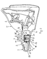
- in perspektivischer Darstellung einen Spiegelfuß eines erfindungsgemäßen Außenrückblickspiegels mit einer Umfeldleuchte im Schnitt,
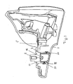
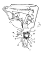
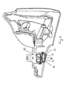
- Fig. 2 bis 6
- jeweils eine weitere Ausführungsform eines erfindungsgemäßen Außenrückblickspiegels in Darstellungen gemäß Fig. 1.
- Fig. 1 zeigt einen Spiegelfuß 1 mit einer Abdeckung 2 und einer Umfeldleuchte 3 eines Außenrückblickspiegels, der über den Spiegelfuß 1 an einem (nicht dargestellten) Fahrzeug befestigt ist. Am Spiegelfuß 1 wird ein (nicht dargestellter) Spiegelkopf angelenkt, der aus einer Gebrauchslage in eine Außergebrauchslage benachbart zum Fahrzeug verschwenkt werden kann. Mit der Umfeldleuchte 3 wird ein Bereich unterhalb des Außenrückblickspiegels und benachbart zum Fahrzeug bzw. der Fahrzeugtüre beleuchtet.
- Der Spiegelfuß 1 hat eine Aufnahme 4 für die Leuchte 3, die vorzugsweise von einem umlaufenden Steg 5 gebildet wird. Die Aufnahme 4 kann eckigen oder runden Querschnitt haben. Entsprechend der unterschiedlichen Bauhöhe des Spiegelfußes 1 im Bereich des Einbauraumes der Umfeldleuchte 3 hat der Steg 5 über seinen Umfang unterschiedliche Höhe. Im Ausführungsbeispiel liegt die Aufnahme 4 im Bereich einer Bohrung 7, die einen Lagerbolzen zur schwenkbaren Lagerung des Spiegelkopfes aufnimmt.
- Der Spiegelfuß 1 hat einen Tragkörper 1', der vorzugsweise aus Metall oder aus hartem Kunststoff besteht. Der Tragkörper 1' ist nach außen durch die kappenartig ausgebildete Abdeckung 2 abgedeckt, die eine Öffnung 9 für ein Lichtfester 10 der Leuchte 3 aufweist. Die Abdeckung 2 besteht vorteilhaft aus Kunststoff. Sie wird über eine oder mehrere Formschlußverbindungen 11 auf dem Tragkörper 1' gehalten. Die Abdeckung hat einen umgebogenen Randabschnitt 12 und einen etwa parallel und mit Abstand dazu liegenden inneren Steg 13, die eine Aufnahmeöffnung 14 für einen freien Rand 15 des Tragkörpers 1' begrenzen.
- Die Umfeldleuchte 3 hat als Leuchtmittel eine LED 16, die auf einer Platine 17 angeordnet ist, und ein Leuchtengehäuse 18, das das Lichtfenster 10 aufweist. Die Platine 17 ist eine ebene Kunststoffplatte, die einen (nicht dargestellten) Metallkern, vorzugsweise eine gleiche Umrißform aufweisende Metallplatte als Wärmeleiter enthält. In der Einbaulage liegt die Metallkernplatine 16 flächig auf dem ebenen Boden 8 der Aufnahme 4 auf.
- Das Leuchtengehäuse 18 ist einteilig mit dem Lichtfenster 10 aus einem lichtdurchlässigen Kunststoff hergestellt. Das Gehäuse hat kreisförmigen Querschnitt mit einem umlaufenden, im Querschnitt L-förmigen Rand 19, der eine Ringnut 20 für eine Ringdichtung 21 begrenzt. In die Ringnut 20 ragt das freie Ende des Steges 5 der Aufnahme 4 des Tragkörpers 1'. Auf diese Weise ist das Gehäuse 18 in montierter Lage in der Aufnahme 4 gegen Verdrehen gesichert. Die Platine 17 schließt das Gehäuse 18 an dem dem Lichtfenster 10 gegenüberliegenden Ende.
- Das Lichtfester 10 ragt mit einem zentralen Abschnitt 22 so in die Gehäuseöffnung 9, daß die Stirnfläche 25 des Abschnittes 22 in der Außenseite der Abdeckung 2 liegt. Der Gehäuseabschnitt 22 füllt die Öffnung 9 vollständig aus und geht über eine Schulter 24 in den übrigen Gehäuseteil über. Die Stirnfläche 25 ist mit großem Krümmungsradius teilkreisförmig nach außen über die anschließende Wand 30 der Abdeckung 2 gewölbt. In montierter Lage der Abdeckung 2 ragt das Lichtfenster 10 in die Öffnung 9 der Abdeckung 2, so daß der Öffnungsrand 26 in der Schulter 24 liegt. Das Leuchtengehäuse 18 liegt benachbart zum Öffnungsrand 26 auf der Innenseite der Abdekkung 2 auf. Die Höhe des Leuchtengehäuses 18 ist geringfügig größer als der Abstand, den die Abdeckung 2 im Bereich des Gehäuses vom Boden 8 der Aufnahme 4 des Tragkörpers 1' hat. Dadurch wird das Leuchtengehäuse 18 in montierter Lage und bei montierter Abdeckung 2 gegenüber der Platine 17 vorgespannt, so daß diese unter Vorspannung am Boden 8 der Spiegelfußaufnahme 4 anliegt. Da die LED 16 sehr hohe Lumenwerte pro Watt erzeugt, tritt eine starke Wärmeentwicklung auf, die über den Metallkern in der Platine 17 unmittelbar auf den Tragkörper 1' übertragen bzw. an diesen abgeleitet wird. Auf diese Weise wird die Umfeldleuchte 3 bzw. ihr Gehäuse 18 vor übermäßiger Erwärmung oder vor Überhitzen geschützt.
- Die Abdeckung 2 wird über das vormontierte Lichtfenster 10 geschoben. Dabei gleitet die Abdeckung 2 unter elastischer Aufweitung auf der Stirnfläche 25 des Lichtfensters 10, bis der Öffnungsrand 26 in die Schulter 24 des Lichtfensters einschnappt. Auf diese Weise wird das Lichtfenster 10 gegen den Träger 17 verspannt und gehalten. Zusätzliche Befestigungsmittel für das Lichtfenster 10 sind somit nicht notwendig.
- Durch die Vorspannung des Leuchtengehäuses 18 wird auch die Dichtung 21 zwischen dem Steg 5 und dem Gehäuse 18 elastisch zusammengedrückt, so daß zuverlässig das Eindringen von Feuchtigkeit in das Gehäuse 18 verhindert wird.
- Die Ausführungsform gemäß Fig. 2 unterscheidet sich von der zuvor beschriebenen Ausführungsform nur dadurch, daß das Leuchtengehäuse 18 einen vorzugsweise ringförmigen Hohlraum 27 aufweist, der zwischen den Gehäusewänden 29, 29' und einem zentralen Mittelteil 28 vorgesehen ist. Dieser Mittelteil 28 weist an seinem freien Ende eine Ausnehmung 28' auf, in die bei montiertem Leuchtengehäuse 18 die LED 16 formschlüssig ragt. Das Lichtfenster 10 hat den zentralen, vorstehenden Gehäuseabschnitt 22, der in der Öffnung 9 liegt. Die Stirnseite 25 des zentralen Gehäuseabschnittes 22 ist im Unterschied zur zuvor beschriebenen Ausführungsform konvex gekrümmt ausgebildet, so daß sie etwa in einer Ebene mit der angrenzenden Wand 30 der Abdeckung 2 liegt. Auch bei dieser Ausführungsform besteht das Leuchtengehäuse 18 aus lichtdurchlässigem Kunststoff.
- Das Gehäuse 18 weist unmittelbar an die Außenschulter 24 anschließend eine weitere Außenschulter 43 auf, in der eine Ringdichtung 42 angeordnet ist. In der Einbaulage liegt sie unter elastischer Verformung zwischen dem Leuchtengehäuse 18 und der Innenseite der Abdeckung 2 und verhindert den Zutritt von Feuchtigkeit und/oder Schmutz durch die Öffnung 9 in den Spiegelfuß 1. Im übrigen ist diese Ausführungsform gleich ausgebildet wie das vorige Ausführungsbeispiel. Die Metallkernplatine 17 wird wiederum fest gegen den Boden 8 der Aufnahme 4 des Tragkörpers 1' gedrückt, so daß die bei eingeschalteter LED 16 entstehende Wärme zuverlässig in den Tragkörper 1' geleitet wird.
- Die Ausführungsform nach Fig. 3 entspricht der nach Fig. 2 mit dem einzigen Unterschied, daß das Leuchtengehäuse 18 ohne den Mittelteil 28 ausgebildet ist. Die LED 16 mit der den Metallkern aufweisenden Platine 17 liegt wieder auf dem Boden 8 der Aufnahme 4 des Tragkörpers 1' unter Druck ganzflächig auf. Das Gehäuse 18 ist in montierter Lage gemäß Fig. 3 durch die Abdeckung 2 in Richtung auf den Tragkörper 1' belastet. Dadurch wird die Ringdichtung 21 in der Ringnut 20 elastisch verformt und die Platine 17 gegen den Boden 8 der Aufnahme 4 gedrückt, so daß eine schnelle und einwandfreie Wärmeableitung und eine zuverlässige Abdichtung des Gehäuses 18 gewährleistet sind.
- Fig. 4 zeigt eine Ausführungsform entsprechend Fig. 3, wobei das Gehäuse 18 als Einsatz 31 einen Reflektor aufweist. Er liegt an der Innenwand des Gehäuses 18 an und ist mit einer Öffnung 32 versehen, durch welche die LED 16 ragt. Der Reflektor 31 hat eine Reflektorfläche 33, daß das von der LED 16 ausgesandte Licht zum Lichtfenster 10 reflektiert. Der Reflektor 31 kann je nach gewünschter Leuchtwirkung unterschiedlich gestaltet sein, beispielsweise als Paraboloid. Mit seinem freien Rand stützt sich der Reflektor 31 an einer Innenschulter 34 des Gehäuses 18 ab, die auch bei den Gehäusen gemäß den Fig. 2 und 3 vorgesehen ist. Die Innenschulter 34 ist gegenüber der Außenschulter 24 nach innen zurückversetzt. Der Reflektor 31 liegt außerdem auf der Platine 17 auf. Der Reflektor 31 besteht vorzugsweise aus hitzebeständigem Kunststoff. Im übrigen ist die Umfeldleuchte 3 gleich ausgebildet wie die bei der Ausführungsform gemäß Fig. 3.
- Der Reflektor 31 kann auch als wärmeableitendes Element ausgebildet sein. In diesem Falle besteht er aus metallischem Werkstoff und ist so ausgebildet, daß er die Form des Leuchtengehäuses 18 hat. Die Ringnut 20 ist dann an der Außenseite des Reflektors 31 vorgesehen. In das freie Ende eines solchen Reflektors ist dann eine Lichtscheibe eingesetzt. Die von der LED 16 erzeugte Wärme wird bei einer solchen Ausbildung nicht nur über den Träger 17 in den Tragkörper 1', sondern auch über den Reflektor 31 in den Steg 5 abgeleitet.
- Über die Platine 17 der Umfeldleuchte 3 wird auch hier die von der LED 16 erzeugte Wärme schnell und vollständig in den Tragkörper 1' abgeleitet.
- Fig. 5 zeigt eine Ausführungsform, bei der das Leuchtengehäuse 18 im wesentlichen dem nach Fig. 3 entspricht. Nur die Stirnfläche 25 des zentralen Abschnittes 22 des Lichtfensters 10 ist entsprechend der Ausführungsform nach Fig. 1 konkav gewölbt. Die Innenseite des Lichtfensters 10 ist mit einer Optikstruktur 38 versehen, mit der eine gezielte Lenkung des von der LED 16 abgestrahlten Lichtes erreicht werden kann. Mit Abstand hinter dem Lichtfenster 10 ist ein Optikelement 39 angeordnet, das beispielsweise als Fresnellinse ausgebildet ist. Zwischen dem Optikelement 39 und der LED 16 ist eine Linse 40 im Gehäuse 18 untergebracht. Die Optikelemente 38 bis 40 können selbstverständlich auch in anderer Anordnung im Gehäuse eingebaut sein. Es können auch unterschiedliche Kombinationen dieser Optikelemente eingesetzt werden, um eine gezielte Lenkung des Lichtes zu erreichen.
- Bei der Ausführungsform nach Fig. 6 sind wie beim vorigen Ausführungsbeispiel die Optikelemente 38 bis 40 vorgesehen. Zusätzlich ist die Stirnseite 25 des Lichtfensters 10 mit einer Optikstruktur 41 versehen.
- Anstelle des Leuchtengehäuses 18 kann auch ein Lichtleiter verwendet werden oder eine Kombination aus einem Lichtleiter und dem Gehäuse 18. Die Einbautiefe der LED 16 kann bei entsprechender Anpassung des Spiegelfußes ebenfalls variiert werden; um das Leuchtfeld zu verändern.
- Schließlich kann auch die Lage der Umfeldbeleuchtung 3 auf dem Spiegelfuß 1 je nachdem, welcher Bereich neben dem Fahrzeug und am Boden ausgeleuchtet werden soll, beliebig verändert werden.
- Selbstverständlich können anstelle der einen LED 16 auch weitere, beispielsweise in Reihe nebeneinander angeordnete LEDs vorgesehen werden, um die Lichtintensität zu erhöhen.
- Bei allen beschriebenen Ausführungsformen können im Außenrückblickspiegel, insbesondere im Spiegelkopf, Leuchtmittel als Wiederholblinkleuchte, Sender und/oder Empfänger von Garagentoröffnern, und/oder von Navigationssystemen, Sensoren als Teil der Steuerung eines EC- oder eines LCD-Glases, Antennen für Autoradios, Kompaß und dgl., Lautsprecher und dgl. eingebaut sein. Auch im Spiegelfuß können weitere Bauteile vorgesehen sein, wie Sender und/oder Empfänger von Garagentoröffnern oder von Navigationssystemen.
Claims (37)
- Außenrückblickspiegel für Fahrzeuge, insbesondere Kraftfahrzeuge, mit einem am Fahrzeug zu befestigenden Spiegelfuß (1), an dem ein abklappbarer Spiegelkopf befestigt ist, und mit mindestens einer im Spiegelfuß (1) angeordneten Umfeldleuchte (3) mit mindestens einem Leuchtmittel (16), vorzugsweise einer LED, das auf einem Träger (17) angeordnet ist,
dadurch gekennzeichnet, daß der Träger (17) einen metallischen Wärmeleiter enthält, der zur Wärmeableitung unmittelbar an einem wärmeableitenden Tragkörper (1') des Spiegelfußes (1) anliegt. - Außenrückblickspiegel nach Anspruch 1,
dadurch gekennzeichnet, daß der Wärmeleiter plattenartig ausgebildet ist. - Außenrückblickspiegel nach Anspruch 1 oder 2,
dadurch gekennzeichnet, daß der Wärmeleiter versenkt im Träger (17) angeordnet ist, der vorzugsweise durch eine Leiterplatine gebildet ist. - Außenrückblickspiegel nach einem der Ansprüche 1 bis 3,
dadurch gekennzeichnet, daß das Leuchtmittel (16) mit dem Träger (17) eine Baueinheit bildet. - Außenrückblickspiegel nach einem der Ansprüche 1 bis 4,
dadurch gekennzeichnet, daß auf dem Träger (17) ein das Leuchtmittel (16) aufnehmendes Leuchtengehäuse (18) angeordnet ist. - Außenrückblickspiegel nach Anspruch 5,
dadurch gekennzeichnet, daß das Leuchtengehäuse (18) ein Lichtfenster (10) aufweist. - Außenrückblickspiegel nach Anspruch 5 oder 6,
dadurch gekennzeichnet, daß das Leuchtengehäuse (18) aus hitzebeständigem Material, vorzugsweise Kunststoff, besteht. - Außenrückblickspiegel nach einem der Ansprüche 5 bis 7,
dadurch gekennzeichnet, daß das Leuchtengehäuse (18) und das Lichtfenster (10) einteilig ausgebildet sind. - Außenrückblickspiegel, insbesondere nach einem der Ansprüche 5 bis 8,
dadurch gekennzeichnet, daß das Leuchtengehäuse (18) gegenüber dem Träger (17) in montierter Lage derart vorgespannt ist, daß der Wärmeleiter des Trägers (17) unter Vorspannung an den Teilen des Spiegelfußes (1) anliegt. - Außenrückblickspiegel nach einem der Ansprüche 5 bis 9,
dadurch gekennzeichnet, daß das Leuchtengehäuse (18) unter Zwischenlage mindestens einer Dichtung (21) am Spiegelfuß (1) anliegt. - Außenrückblickspiegel nach Anspruch 10,
dadurch gekennzeichnet, daß die Dichtung (21) eine Ringdichtung ist. - Außenrückblickspiegel nach Anspruch 10 oder 11,
dadurch gekennzeichnet, daß die Dichtung (21) in einer Ringnut (20) liegt. - Außenrückblickspiegel nach einem der Ansprüche 5 bis 12,
dadurch gekennzeichnet, daß das Leuchtengehäuse (18) verdrehsicher im Spiegelfuß (1) gehalten ist. - Außenrückblickspiegel, insbesondere nach einem der Ansprüche 5 bis 13,
dadurch gekennzeichnet, daß das Leuchtengehäuse (18) durch eine Abdeckung (2) des Spiegelfußes (1) gegen den Träger (17) derart verspannt ist, daß der Wärmeleiter des Trägers (17) unter Vorspannung an den Teilen des Spiegelfußes (1) anliegt. - Außenrückblickspiegel nach Anspruch 14,
dadurch gekennzeichnet, daß die Abdeckung (2) an dem Tragkörper (1') des Spiegelfußes (1) über eine Rastverbindung, vorzugsweise eine Schnappverbindung, gehalten ist. - Außenrückblickspiegel nach Anspruch 14 oder 15,
dadurch gekennzeichnet, daß zwischen der Abdeckung (2) und dem Leuchtengehäuse (18) eine weitere Dichtung (42) angeordnet ist. - Außenrückblickspiegel nach einem der Ansprüche 6 bis 16,
dadurch gekennzeichnet, daß das Lichtfenster (10) über eine Außenschulter (24) in den übrigen Gehäuseteil übergeht. - Außenrückblickspiegel nach Anspruch 17,
dadurch gekennzeichnet, daß die Abdeckung (2) mit einem Rand (26) in die Außenschulter (24) des Leuchtengehäuses (18) eingreift. - Außenrückblickspiegel nach einem der Ansprüche 16 bis 18,
dadurch gekennzeichnet, daß die weitere Dichtung (42) in einer weiteren Außenschulter (43) des Leuchtengehäuses (18) liegt. - Außenrückblickspiegel nach einem der Ansprüche 14 bis 19,
dadurch gekennzeichnet, daß das Leuchtengehäuse (18) an der Innenseite der Abdeckung (2) abgestützt ist. - Außenrückblickspiegel nach einem der Ansprüche 5 bis 20,
dadurch gekennzeichnet, daß das Leuchtengehäuse (18) an seiner vom Lichtfenster (10) abgewandten Rückseite eine Vertiefung (28') aufweist, in die das Leuchtmittel (16) bei montiertem Leuchtengehäuse ragt. - Außenrückblickspiegel nach einem der Ansprüche 5 bis 21,
dadurch gekennzeichnet, daß das Leuchtengehäuse (18) napfförmig ausgebildet ist. - Außenrückblickspiegel nach einem der Ansprüche 5 bis 22,
dadurch gekennzeichnet, daß das Leuchtengehäuse (18) einen Mittelteil (28) aufweist. - Außenrückblickspiegel nach Anspruch 23,
dadurch gekennzeichnet, daß der Mittelteil (28) die Vertiefung (28') zur Aufnahme des Leuchtmittels (16) aufweist. - Außenrückblickspiegel nach einem der Ansprüche 5 bis 24,
dadurch gekennzeichnet, daß im Leuchtengehäuse (18) ein Reflektor (31) untergebracht ist. - Außenrückblickspiegel nach Anspruch 25,
dadurch gekennzeichnet, daß das Leuchtmittel (16) in den Reflektor (31) ragt. - Außenrückblickspiegel nach Anspruch 25 oder 26,
dadurch gekennzeichnet, daß der Reflektor (31) auf dem Träger (17) aufsitzt. - Außenrückblickspiegel nach einem der Ansprüche 25 bis 27,
dadurch gekennzeichnet, daß sich der Reflektor (31) an einer Innenschulter (34) des Leuchtengehäuses (18) abstützt. - Außenrückblickspiegel nach einem der Ansprüche 25 bis 28,
dadurch gekennzeichnet, daß der Reflektor (31) aus hitzebeständigem Material, vorzugsweise Kunststoff, besteht. - Außenrückblickspiegel nach einem der Ansprüche 25 bis 29,
dadurch gekennzeichnet, daß der Reflektor (31) aus wärmeableitendem Material, vorzugsweise Metall, besteht. - Außenrückblickspiegel nach Anspruch 30,
dadurch gekennzeichnet, daß der Reflektor (31) einen Teil des Leuchtengehäuses (8) bildet. - Außenrückblickspiegel nach einem der Ansprüche 5 bis 31,
dadurch gekennzeichnet, daß das Leuchtengehäuse (18) mindestens ein, vorzugsweise mehrere Optikelemente (38 bis 41) aufweist. - Außenrückblickspiegel nach einem der Ansprüche 6 bis 32,
dadurch gekennzeichnet, daß das Lichtfenster (10) in einer Öffnung (9) des Spiegelfußes (1), insbesondere der Abdeckung (2), liegt. - Außenrückblickspiegel nach einem der Ansprüche 6 bis 33,
dadurch gekennzeichnet, daß die Stirnseite (22) des Lichtfensters (10) im wesentlichen eine Fortsetzung der Außenseite der Abdeckung (2) bildet. - Außenrückblickspiegel nach einem der Ansprüche 15 bis 34,
dadurch gekennzeichnet, daß der Tragkörper (1') des Spiegelfußes (1) eine Aufnahme (4) für das Leuchtengehäuse (18) aufweist. - Außenrückblickspiegel nach Anspruch 35,
dadurch gekennzeichnet, daß die Aufnahme (4) durch Stege (5, 6) des Tragkörpers (1') begrenzt ist. - Außenrückblickspiegel nach Anspruch 35 oder 36,
dadurch gekennzeichnet, daß der Träger (17) unter Druckbelastung durch das Leuchtengehäuse (18) am Boden (8) der Aufnahme (4) flächig anliegt.
Applications Claiming Priority (3)
| Application Number | Priority Date | Filing Date | Title |
|---|---|---|---|
| DE10256197 | 2002-12-02 | ||
| DE10256197A DE10256197A1 (de) | 2002-12-02 | 2002-12-02 | Außenrückblickspiegel für Fahrzeuge, insbesondere Kraftfahrzeuge |
| PCT/DE2003/003904 WO2004050428A1 (de) | 2002-12-02 | 2003-11-26 | Aussenrückspiegel für fahrzeuge |
Publications (2)
| Publication Number | Publication Date |
|---|---|
| EP1567390A1 EP1567390A1 (de) | 2005-08-31 |
| EP1567390B1 true EP1567390B1 (de) | 2007-01-10 |
Family
ID=32308906
Family Applications (1)
| Application Number | Title | Priority Date | Filing Date |
|---|---|---|---|
| EP03767450A Expired - Lifetime EP1567390B1 (de) | 2002-12-02 | 2003-11-26 | Aussenrückblickspiegel für fahrzeuge |
Country Status (6)
| Country | Link |
|---|---|
| US (1) | US7682056B2 (de) |
| EP (1) | EP1567390B1 (de) |
| KR (1) | KR100946092B1 (de) |
| AU (1) | AU2003291945A1 (de) |
| DE (3) | DE10256197A1 (de) |
| WO (1) | WO2004050428A1 (de) |
Families Citing this family (18)
| Publication number | Priority date | Publication date | Assignee | Title |
|---|---|---|---|---|
| US7195382B1 (en) * | 2004-06-30 | 2007-03-27 | Magna Donnelly Mirrors North America, L.L.C. | Vehicle mirror with secondary lighting lens for ground illuminator |
| DE102005047189B4 (de) * | 2005-09-23 | 2013-03-07 | SMR Patents S.à.r.l. | Außenrückblickspiegel für Kraftfahrzeuge |
| US7404655B2 (en) * | 2006-05-10 | 2008-07-29 | Gentex Corporation | Vehicle rearview assembly including a map light |
| US20090086346A1 (en) * | 2007-10-01 | 2009-04-02 | Schefenacker Vision Systems Usa, Inc. | Side mirror assembly for a motor vehicle |
| DE102009019092A1 (de) * | 2009-04-20 | 2010-11-04 | SMR Patents S.à.r.l. | Minimaler LED Blinker im Außenspiegel |
| JP5734762B2 (ja) * | 2011-06-22 | 2015-06-17 | 株式会社東海理化電機製作所 | 車両用ミラー装置 |
| KR101218797B1 (ko) * | 2012-01-02 | 2013-01-04 | 주식회사 파인디앤씨 | 디스플레이 장치용 백라이트 유닛의 광원장치 |
| AT514405B1 (de) * | 2013-06-07 | 2015-05-15 | Zkw Slovakia S R O | Beleuchtungskörper für ein Fahrzeug |
| DE102016002575A1 (de) * | 2016-03-03 | 2017-09-07 | GM Global Technology Operations LLC (n. d. Ges. d. Staates Delaware) | Außenspiegelhalter |
| DE102017119542A1 (de) * | 2017-08-25 | 2019-02-28 | SMR Patents S.à.r.l. | Rückblickvorrichtung und Fahrzeug mit einer solchen Rückblickvorrichtung |
| US11305696B2 (en) * | 2017-08-25 | 2022-04-19 | SMR Patents S.à.r.l. | Rearview device and vehicle with such rearview device |
| US10391929B1 (en) | 2018-08-20 | 2019-08-27 | Ficosa North America Corporation | Lighted path system for vehicle |
| JP7298094B2 (ja) * | 2019-09-09 | 2023-06-27 | 株式会社東海理化電機製作所 | 車両用投射装置及び車両用視認装置 |
| CN212929936U (zh) * | 2020-08-20 | 2021-04-09 | 肯舒摩照明(美国)有限责任公司 | 感测装置和照明装置 |
| CN113776022B (zh) * | 2021-11-15 | 2022-02-11 | 深圳市金风驰科技有限公司 | 一种摩托车照明装置 |
| US20230331149A1 (en) | 2022-04-14 | 2023-10-19 | Magna Exteriors Inc. | Integrated in-surface lens assembly |
| US12377781B2 (en) * | 2022-04-14 | 2025-08-05 | Magna Exteriors, Inc. | Integrated in-surface lens assembly |
| JP2024158524A (ja) * | 2023-04-27 | 2024-11-08 | 美里工業株式会社 | 車両用ドアミラー及びその製造方法 |
Family Cites Families (25)
| Publication number | Priority date | Publication date | Assignee | Title |
|---|---|---|---|---|
| US1223981A (en) * | 1916-02-08 | 1917-04-24 | Axel W Johnson | Automobile signaling device. |
| US1381561A (en) * | 1919-08-21 | 1921-06-14 | Johnson Samuel Sylvester | Signal device or indicator |
| US1368644A (en) * | 1920-05-12 | 1921-02-15 | Jack K Mochizuki | Signaling device |
| US1814728A (en) * | 1930-06-05 | 1931-07-14 | Moore George | Combined rear view mirror and parking light for automobiles |
| US2595331A (en) * | 1950-01-30 | 1952-05-06 | Paul F Calihan | Combination vision mirror and signaling device |
| US4211955A (en) * | 1978-03-02 | 1980-07-08 | Ray Stephen W | Solid state lamp |
| US5017903C1 (en) * | 1989-02-21 | 2002-08-13 | Jacob Krippelz Sr | Emergency light |
| US5014167A (en) * | 1990-02-20 | 1991-05-07 | K. W. Muth Company, Inc. | Visual signaling apparatus |
| US5160200A (en) * | 1991-03-06 | 1992-11-03 | R & D Molded Products, Inc. | Wedge-base LED bulb housing |
| US5669699A (en) * | 1994-11-02 | 1997-09-23 | Donnelly Corporation | Exterior vehicle security light |
| US5660457A (en) * | 1995-11-07 | 1997-08-26 | Whelen Engineering Company, Inc. | Integrated warning light and rear-view mirror |
| US6152590A (en) * | 1998-02-13 | 2000-11-28 | Donnelly Hohe Gmbh & Co. Kg | Lighting device for motor vehicles |
| US6572250B1 (en) * | 1999-03-15 | 2003-06-03 | Britax Wingard Limited | Exterior mirror having an attachment member including an approach light |
| US6371636B1 (en) * | 1999-05-24 | 2002-04-16 | Jam Strait, Inc. | LED light module for vehicles |
| US6049271A (en) * | 1999-06-29 | 2000-04-11 | Chu; Ching-Ti | Vehicle rearview mirror with multiple signal means |
| US6227689B1 (en) * | 1999-09-28 | 2001-05-08 | Donnelly Corporation | Illumination device for exterior mirror |
| EP1292931B1 (de) * | 2000-02-11 | 2013-04-03 | SMR Patents S.à.r.l. | Aussenspiegel |
| US7195381B2 (en) * | 2001-01-23 | 2007-03-27 | Donnelly Corporation | Vehicle interior LED lighting system |
| ES2168071B1 (es) * | 2000-07-12 | 2003-07-16 | Barros Alejandro Rodriguez | Retrovisor modular con señales multiples intercambiables para vehiculos de 2, 3, 4 o mas ruedas. |
| US6357902B1 (en) * | 2000-09-25 | 2002-03-19 | Brian Horowitz | After market LED taillight bulb |
| DE60223050T2 (de) * | 2001-08-31 | 2008-07-17 | Gentex Corp., Zeeland | Fahrzeuglampenanordnung mit kühlkörper |
| US6827468B2 (en) * | 2001-12-10 | 2004-12-07 | Robert D. Galli | LED lighting assembly |
| US20040022064A1 (en) * | 2002-07-31 | 2004-02-05 | Fang-Mei Kuo | Lamp for the rear-view mirror of a vehicle |
| DE10308073A1 (de) * | 2003-02-26 | 2004-09-09 | Schefenacker Vision Systems Germany Gmbh & Co. Kg | Außenrückblickspiegel für Fahrzeuge, vorzugsweise für Kraftfahrzeuge |
| US7195382B1 (en) * | 2004-06-30 | 2007-03-27 | Magna Donnelly Mirrors North America, L.L.C. | Vehicle mirror with secondary lighting lens for ground illuminator |
-
2002
- 2002-12-02 DE DE10256197A patent/DE10256197A1/de not_active Withdrawn
-
2003
- 2003-11-26 WO PCT/DE2003/003904 patent/WO2004050428A1/de not_active Ceased
- 2003-11-26 DE DE50306279T patent/DE50306279D1/de not_active Expired - Lifetime
- 2003-11-26 US US10/537,165 patent/US7682056B2/en not_active Expired - Fee Related
- 2003-11-26 DE DE10394128T patent/DE10394128D2/de not_active Expired - Fee Related
- 2003-11-26 KR KR1020047019576A patent/KR100946092B1/ko not_active Expired - Fee Related
- 2003-11-26 EP EP03767450A patent/EP1567390B1/de not_active Expired - Lifetime
- 2003-11-26 AU AU2003291945A patent/AU2003291945A1/en not_active Abandoned
Also Published As
| Publication number | Publication date |
|---|---|
| EP1567390A1 (de) | 2005-08-31 |
| KR20050088261A (ko) | 2005-09-05 |
| DE10394128D2 (de) | 2005-10-27 |
| KR100946092B1 (ko) | 2010-03-10 |
| WO2004050428A1 (de) | 2004-06-17 |
| US20060133101A1 (en) | 2006-06-22 |
| DE50306279D1 (de) | 2007-02-22 |
| DE10256197A1 (de) | 2004-06-09 |
| US7682056B2 (en) | 2010-03-23 |
| AU2003291945A1 (en) | 2004-06-23 |
Similar Documents
| Publication | Publication Date | Title |
|---|---|---|
| EP1567390B1 (de) | Aussenrückblickspiegel für fahrzeuge | |
| EP1598237B1 (de) | Aussenrückblickspiegel für Fahrzeuge, insbesondere Kraftfahrzeuge | |
| EP0858932B2 (de) | Aussenrückblickspiegel für Fahrzeuge, vorzugsweise für Kraftfahrzeuge | |
| DE19805771A1 (de) | Beleuchtungseinrichtung für Kraftfahrzeuge | |
| DE102005013682B4 (de) | Außenrückblickspiegel von Fahrzeugen, vorzugsweise von Kraftfahrzeugen | |
| DE20001407U1 (de) | Außenrückblickspiegel für Fahrzeuge, vorzugsweise für Kraftfahrzeuge | |
| EP1757487A1 (de) | Außenrückblickspiegel für Fahrzeuge | |
| WO2005113291A1 (de) | Aussenrückblickspiegel für fahrzeuge, insbesondere für kraftfahrzeuge | |
| EP0961074A2 (de) | Beleuchtungseinrichtung für Fahrzeuge | |
| EP0745511A2 (de) | Beleuchtungseinrichtung für Fahrzeuge | |
| DE102007010747A1 (de) | Außenrückblickspiegel für Fahrzeuge, insbesondere Kraftfahrzeuge | |
| DE102004018695A1 (de) | Außenrückblickspiegel für Fahrzeuge, vorzugsweise Kraftfahrzeuge | |
| EP2239498B1 (de) | Leuchte mit umlaufender Dichtlippe | |
| DE19546271B4 (de) | Scheinwerfer für Fahrzeuge mit einem verschwenkbaren Reflektor | |
| DE102011118219A1 (de) | Leuchteinrichtung für ein Kraftfahrzeug | |
| DE102005012104A1 (de) | Gehäuse, insbesondere Spiegelgehäuse | |
| EP1964720B1 (de) | Aussenrückblickspiegel für Fahrzeuge, vorzugsweise für Kraftfahrzeuge | |
| DE10320307B4 (de) | Innenleuchte eines Fahrzeugs | |
| DE10339833A1 (de) | Beleuchtetes Stellrad | |
| GB2261497A (en) | Lamp for motor vehicles | |
| DE19838911B4 (de) | Beleuchtungseinrichtung eines Fahrzeugs | |
| WO2004076236A1 (de) | Aussenrückblickspiegel für kraftfahrzeuge | |
| EP2828125B1 (de) | Anordnung zum bereitstellen einer innenraumbeleuchtung eines fahrzeugs und verfahren zum herstellen derselben | |
| EP0735310A2 (de) | Fahrzeugleuchte mit Freiformflächenreflektor und brillanter transparenter Abdeckscheibe | |
| DE102015119445A1 (de) | Verfahren zur Herstellung einer Designeinrichtung für Fahrzeuge sowie Beleuchtungsvorrichtung |
Legal Events
| Date | Code | Title | Description |
|---|---|---|---|
| PUAI | Public reference made under article 153(3) epc to a published international application that has entered the european phase |
Free format text: ORIGINAL CODE: 0009012 |
|
| 17P | Request for examination filed |
Effective date: 20050203 |
|
| AK | Designated contracting states |
Kind code of ref document: A1 Designated state(s): AT BE BG CH CY CZ DE DK EE ES FI FR GB GR HU IE IT LI LU MC NL PT RO SE SI SK TR |
|
| AX | Request for extension of the european patent |
Extension state: AL LT LV MK |
|
| DAX | Request for extension of the european patent (deleted) | ||
| RBV | Designated contracting states (corrected) |
Designated state(s): DE FR GB |
|
| GRAP | Despatch of communication of intention to grant a patent |
Free format text: ORIGINAL CODE: EPIDOSNIGR1 |
|
| GRAS | Grant fee paid |
Free format text: ORIGINAL CODE: EPIDOSNIGR3 |
|
| GRAA | (expected) grant |
Free format text: ORIGINAL CODE: 0009210 |
|
| RAP1 | Party data changed (applicant data changed or rights of an application transferred) |
Owner name: SCHEFENACKER VISION SYSTEMS GERMANY GMBH |
|
| AK | Designated contracting states |
Kind code of ref document: B1 Designated state(s): DE FR GB |
|
| REG | Reference to a national code |
Ref country code: GB Ref legal event code: FG4D Free format text: NOT ENGLISH |
|
| REF | Corresponds to: |
Ref document number: 50306279 Country of ref document: DE Date of ref document: 20070222 Kind code of ref document: P |
|
| GBT | Gb: translation of ep patent filed (gb section 77(6)(a)/1977) |
Effective date: 20070425 |
|
| ET | Fr: translation filed | ||
| PLBE | No opposition filed within time limit |
Free format text: ORIGINAL CODE: 0009261 |
|
| STAA | Information on the status of an ep patent application or granted ep patent |
Free format text: STATUS: NO OPPOSITION FILED WITHIN TIME LIMIT |
|
| 26N | No opposition filed |
Effective date: 20071011 |
|
| REG | Reference to a national code |
Ref country code: GB Ref legal event code: 732E Free format text: REGISTERED BETWEEN 20090219 AND 20090225 |
|
| REG | Reference to a national code |
Ref country code: FR Ref legal event code: CD Ref country code: FR Ref legal event code: TP Ref country code: FR Ref legal event code: CA |
|
| REG | Reference to a national code |
Ref country code: DE Ref legal event code: R082 Ref document number: 50306279 Country of ref document: DE Representative=s name: JONES DAY RECHTSANWAELTE PATENTANWAELTE, DE |
|
| PGFP | Annual fee paid to national office [announced via postgrant information from national office to epo] |
Ref country code: FR Payment date: 20121130 Year of fee payment: 10 Ref country code: DE Payment date: 20121121 Year of fee payment: 10 |
|
| PGFP | Annual fee paid to national office [announced via postgrant information from national office to epo] |
Ref country code: GB Payment date: 20121120 Year of fee payment: 10 |
|
| GBPC | Gb: european patent ceased through non-payment of renewal fee |
Effective date: 20131126 |
|
| REG | Reference to a national code |
Ref country code: FR Ref legal event code: ST Effective date: 20140731 |
|
| REG | Reference to a national code |
Ref country code: DE Ref legal event code: R119 Ref document number: 50306279 Country of ref document: DE Effective date: 20140603 |
|
| PG25 | Lapsed in a contracting state [announced via postgrant information from national office to epo] |
Ref country code: DE Free format text: LAPSE BECAUSE OF NON-PAYMENT OF DUE FEES Effective date: 20140603 |
|
| PG25 | Lapsed in a contracting state [announced via postgrant information from national office to epo] |
Ref country code: FR Free format text: LAPSE BECAUSE OF NON-PAYMENT OF DUE FEES Effective date: 20131202 Ref country code: GB Free format text: LAPSE BECAUSE OF NON-PAYMENT OF DUE FEES Effective date: 20131126 |