EP1567390B1 - Retroviseur exterieur destine a des vehicules - Google Patents
Retroviseur exterieur destine a des vehicules Download PDFInfo
- Publication number
- EP1567390B1 EP1567390B1 EP03767450A EP03767450A EP1567390B1 EP 1567390 B1 EP1567390 B1 EP 1567390B1 EP 03767450 A EP03767450 A EP 03767450A EP 03767450 A EP03767450 A EP 03767450A EP 1567390 B1 EP1567390 B1 EP 1567390B1
- Authority
- EP
- European Patent Office
- Prior art keywords
- rearview mirror
- exterior rearview
- mirror according
- lamp housing
- support
- Prior art date
- Legal status (The legal status is an assumption and is not a legal conclusion. Google has not performed a legal analysis and makes no representation as to the accuracy of the status listed.)
- Expired - Lifetime
Links
- 239000002184 metal Substances 0.000 claims description 8
- 230000003287 optical effect Effects 0.000 claims description 8
- 239000004020 conductor Substances 0.000 claims description 7
- 239000003779 heat-resistant material Substances 0.000 claims 2
- 239000000463 material Substances 0.000 claims 1
- 238000010438 heat treatment Methods 0.000 abstract description 3
- 230000001627 detrimental effect Effects 0.000 abstract 1
- 230000002411 adverse Effects 0.000 description 1
- 238000010276 construction Methods 0.000 description 1
- 230000000694 effects Effects 0.000 description 1
- 230000005489 elastic deformation Effects 0.000 description 1
- 239000011521 glass Substances 0.000 description 1
- 230000017525 heat dissipation Effects 0.000 description 1
- 238000009434 installation Methods 0.000 description 1
- 239000007769 metal material Substances 0.000 description 1
- 238000013021 overheating Methods 0.000 description 1
- 230000035515 penetration Effects 0.000 description 1
- 238000007789 sealing Methods 0.000 description 1
- 239000007787 solid Substances 0.000 description 1
Images


Classifications
-
- B—PERFORMING OPERATIONS; TRANSPORTING
- B60—VEHICLES IN GENERAL
- B60R—VEHICLES, VEHICLE FITTINGS, OR VEHICLE PARTS, NOT OTHERWISE PROVIDED FOR
- B60R1/00—Optical viewing arrangements; Real-time viewing arrangements for drivers or passengers using optical image capturing systems, e.g. cameras or video systems specially adapted for use in or on vehicles
- B60R1/12—Mirror assemblies combined with other articles, e.g. clocks
- B60R1/1207—Mirror assemblies combined with other articles, e.g. clocks with lamps; with turn indicators
-
- B—PERFORMING OPERATIONS; TRANSPORTING
- B60—VEHICLES IN GENERAL
- B60Q—ARRANGEMENT OF SIGNALLING OR LIGHTING DEVICES, THE MOUNTING OR SUPPORTING THEREOF OR CIRCUITS THEREFOR, FOR VEHICLES IN GENERAL
- B60Q1/00—Arrangement of optical signalling or lighting devices, the mounting or supporting thereof or circuits therefor
- B60Q1/26—Arrangement of optical signalling or lighting devices, the mounting or supporting thereof or circuits therefor the devices being primarily intended to indicate the vehicle, or parts thereof, or to give signals, to other traffic
- B60Q1/2661—Arrangement of optical signalling or lighting devices, the mounting or supporting thereof or circuits therefor the devices being primarily intended to indicate the vehicle, or parts thereof, or to give signals, to other traffic mounted on parts having other functions
- B60Q1/2665—Arrangement of optical signalling or lighting devices, the mounting or supporting thereof or circuits therefor the devices being primarily intended to indicate the vehicle, or parts thereof, or to give signals, to other traffic mounted on parts having other functions on rear-view mirrors
-
- B—PERFORMING OPERATIONS; TRANSPORTING
- B60—VEHICLES IN GENERAL
- B60R—VEHICLES, VEHICLE FITTINGS, OR VEHICLE PARTS, NOT OTHERWISE PROVIDED FOR
- B60R1/00—Optical viewing arrangements; Real-time viewing arrangements for drivers or passengers using optical image capturing systems, e.g. cameras or video systems specially adapted for use in or on vehicles
- B60R1/02—Rear-view mirror arrangements
- B60R1/06—Rear-view mirror arrangements mounted on vehicle exterior
-
- F—MECHANICAL ENGINEERING; LIGHTING; HEATING; WEAPONS; BLASTING
- F21—LIGHTING
- F21S—NON-PORTABLE LIGHTING DEVICES; SYSTEMS THEREOF; VEHICLE LIGHTING DEVICES SPECIALLY ADAPTED FOR VEHICLE EXTERIORS
- F21S45/00—Arrangements within vehicle lighting devices specially adapted for vehicle exteriors, for purposes other than emission or distribution of light
- F21S45/10—Protection of lighting devices
-
- F—MECHANICAL ENGINEERING; LIGHTING; HEATING; WEAPONS; BLASTING
- F21—LIGHTING
- F21V—FUNCTIONAL FEATURES OR DETAILS OF LIGHTING DEVICES OR SYSTEMS THEREOF; STRUCTURAL COMBINATIONS OF LIGHTING DEVICES WITH OTHER ARTICLES, NOT OTHERWISE PROVIDED FOR
- F21V29/00—Protecting lighting devices from thermal damage; Cooling or heating arrangements specially adapted for lighting devices or systems
- F21V29/50—Cooling arrangements
- F21V29/70—Cooling arrangements characterised by passive heat-dissipating elements, e.g. heat-sinks
- F21V29/74—Cooling arrangements characterised by passive heat-dissipating elements, e.g. heat-sinks with fins or blades
- F21V29/76—Cooling arrangements characterised by passive heat-dissipating elements, e.g. heat-sinks with fins or blades with essentially identical parallel planar fins or blades, e.g. with comb-like cross-section
-
- F—MECHANICAL ENGINEERING; LIGHTING; HEATING; WEAPONS; BLASTING
- F21—LIGHTING
- F21V—FUNCTIONAL FEATURES OR DETAILS OF LIGHTING DEVICES OR SYSTEMS THEREOF; STRUCTURAL COMBINATIONS OF LIGHTING DEVICES WITH OTHER ARTICLES, NOT OTHERWISE PROVIDED FOR
- F21V31/00—Gas-tight or water-tight arrangements
- F21V31/005—Sealing arrangements therefor
-
- F—MECHANICAL ENGINEERING; LIGHTING; HEATING; WEAPONS; BLASTING
- F21—LIGHTING
- F21V—FUNCTIONAL FEATURES OR DETAILS OF LIGHTING DEVICES OR SYSTEMS THEREOF; STRUCTURAL COMBINATIONS OF LIGHTING DEVICES WITH OTHER ARTICLES, NOT OTHERWISE PROVIDED FOR
- F21V5/00—Refractors for light sources
- F21V5/04—Refractors for light sources of lens shape
-
- F—MECHANICAL ENGINEERING; LIGHTING; HEATING; WEAPONS; BLASTING
- F21—LIGHTING
- F21S—NON-PORTABLE LIGHTING DEVICES; SYSTEMS THEREOF; VEHICLE LIGHTING DEVICES SPECIALLY ADAPTED FOR VEHICLE EXTERIORS
- F21S45/00—Arrangements within vehicle lighting devices specially adapted for vehicle exteriors, for purposes other than emission or distribution of light
- F21S45/40—Cooling of lighting devices
- F21S45/47—Passive cooling, e.g. using fins, thermal conductive elements or openings
-
- F—MECHANICAL ENGINEERING; LIGHTING; HEATING; WEAPONS; BLASTING
- F21—LIGHTING
- F21S—NON-PORTABLE LIGHTING DEVICES; SYSTEMS THEREOF; VEHICLE LIGHTING DEVICES SPECIALLY ADAPTED FOR VEHICLE EXTERIORS
- F21S45/00—Arrangements within vehicle lighting devices specially adapted for vehicle exteriors, for purposes other than emission or distribution of light
- F21S45/50—Waterproofing
-
- F—MECHANICAL ENGINEERING; LIGHTING; HEATING; WEAPONS; BLASTING
- F21—LIGHTING
- F21W—INDEXING SCHEME ASSOCIATED WITH SUBCLASSES F21K, F21L, F21S and F21V, RELATING TO USES OR APPLICATIONS OF LIGHTING DEVICES OR SYSTEMS
- F21W2107/00—Use or application of lighting devices on or in particular types of vehicles
- F21W2107/10—Use or application of lighting devices on or in particular types of vehicles for land vehicles
-
- F—MECHANICAL ENGINEERING; LIGHTING; HEATING; WEAPONS; BLASTING
- F21—LIGHTING
- F21Y—INDEXING SCHEME ASSOCIATED WITH SUBCLASSES F21K, F21L, F21S and F21V, RELATING TO THE FORM OR THE KIND OF THE LIGHT SOURCES OR OF THE COLOUR OF THE LIGHT EMITTED
- F21Y2115/00—Light-generating elements of semiconductor light sources
- F21Y2115/10—Light-emitting diodes [LED]
Definitions
- the invention relates to an exterior rearview mirror for vehicles, in particular motor vehicles, according to the preamble of claim 1.
- Exterior rear view mirrors are known (for example from the generic WO 02/08015 A), in which an ambient light is provided on the mirror base which contains at least one light source.
- the bulbs have LEDs, which sit on a board, which is inserted into a housing, which in turn is held in the mirror.
- the bulbs develop a relatively strong heat, which can lead to damage to the ambient light and / or the exterior rearview mirror.
- the invention is based on the object, the generic exterior rearview mirror in such a way that the heat generated by the lamp does not adversely affect.
- the heat generated by the lamp is transmitted from the metallic heat conductor of the carrier directly to the mirror. This can be avoided in a simple way excessive heating of the ambient light and the mirror base.
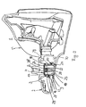
- Fig. 1 shows a mirror 1 with a cover 2 and an ambient light 3 of an exterior rearview mirror, which is attached via the mirror 1 on a vehicle (not shown).
- mirror 1 On mirror 1 a (not shown) mirror head is hinged, which can be pivoted from a position of use in a non-use position adjacent to the vehicle. With the ambient light 3, an area below the exterior rearview mirror and adjacent to the vehicle or the vehicle door is illuminated.
- the mirror 1 has a receptacle 4 for the lamp 3, which is preferably formed by a circumferential ridge 5.
- the receptacle 4 may have square or round cross-section. According to the different height of the mirror base 1 in the region of the installation space of the ambient light 3, the web 5 has different height over its circumference.
- the receptacle 4 is in the region of a bore 7, which receives a bearing pin for pivotally mounting the mirror head.
- the mirror 1 has a support body 1 ', which preferably consists of metal or hard plastic.
- the support body 1 ' is covered to the outside by the cap-like cover 2, which has an opening 9 for a light-solid 10 of the lamp 3.
- the cover 2 is advantageously made of plastic. It is held on one or more form-locking connections 11 on the support body 1 '.
- the cover has a bent edge portion 12 and an approximately parallel and spaced therefrom inner web 13, which define a receiving opening 14 for a free edge 15 of the support body 1 '.
- the ambient light 3 has as a light source an LED 16 which is arranged on a circuit board 17, and a luminaire housing 18 which has the light window 10.
- the circuit board 17 is a flat plastic plate containing a metal core (not shown), preferably a metal plate having the same contour shape as a heat conductor. In the installed position, the metal core board 16 lies flat on the flat bottom 8 of the receptacle 4.
- the light housing 18 is made in one piece with the light window 10 made of a translucent plastic.
- the housing has a circular cross-section with a circumferential, in cross-section L-shaped edge 19 which defines an annular groove 20 for a ring seal 21.
- annular groove 20 protrudes the free end of the web 5 of the receptacle 4 of the support body 1 '. In this way, the housing 18 is secured in the mounted position in the receptacle 4 against rotation.
- the board 17 closes the housing 18 at the opposite end of the light window 10.
- the light-resistant 10 protrudes with a central portion 22 in the housing opening 9, that the end face 25 of the portion 22 is located in the outside of the cover 2.
- the housing portion 22 fills the opening 9 completely and goes through a shoulder 24 in the rest Housing part over.
- the end face 25 is curved with a large radius of curvature part-circular outward over the adjoining wall 30 of the cover 2.
- the light window 10 projects into the opening 9 of the cover 2, so that the opening edge 26 is located in the shoulder 24.
- the lamp housing 18 is adjacent to the opening edge 26 on the inside of the cover 2.
- the height of the lamp housing 18 is slightly larger than the distance that the cover 2 in the region of the housing from the bottom 8 of the receptacle 4 of the support body 1 'has.
- the lamp housing 18 is biased in the mounted position and mounted cover 2 relative to the board 17, so that it rests under pretension on the bottom 8 of the Spiegelfußfact 4. Since the LED 16 produces very high lumen values per watt, a strong heat development occurs, which is transmitted directly to the support body 1 'via the metal core in the circuit board 17 or is dissipated therefrom. In this way, the ambient light 3 or its housing 18 is protected from excessive heating or overheating.
- the cover 2 is pushed over the pre-assembled light window 10.
- the cover 2 slides under elastic expansion on the end face 25 of the light window 10 until the opening edge 26 snaps into the shoulder 24 of the light window. In this way, the light window 10 is clamped and held against the carrier 17. Additional fastening means for the light window 10 are thus not necessary.
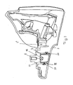
- FIG. 2 differs from the embodiment described above only in that the lamp housing 18 has a preferably annular cavity 27 which is provided between the housing walls 29, 29 'and a central central portion 28.
- This middle part 28 has at its free end a recess 28 ', into which the LED 16 projects in a form-fitting manner when the luminaire housing 18 is mounted.
- the light window 10 has the central projecting housing portion 22 which lies in the opening 9.
- the end face 25 of the central housing portion 22 is formed in contrast to the previously described embodiment convexly curved, so that it lies approximately in a plane with the adjacent wall 30 of the cover 2.
- the lamp housing 18 made of translucent plastic.
- the housing 18 has immediately on the outer shoulder 24 then a further outer shoulder 43, in which an annular seal 42 is arranged. In the installed position it lies under elastic deformation between the lamp housing 18 and the inside of the cover 2 and prevents the ingress of moisture and / or dirt through the opening 9 in the mirror base 1. Otherwise, this embodiment is the same design as the previous embodiment.
- the metal core board 17 is in turn pressed firmly against the bottom 8 of the receptacle 4 of the support body 1 ', so that the heat generated when the LED 16 is turned on reliably in the support body 1' is passed.
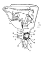
- FIG. 3 corresponds to that of FIG. 2 with the only difference that the lamp housing 18 is formed without the central part 28.
- the LED 16 with the metal core having board 17 is again on the floor 8 of the receptacle 4 of the support body 1 'under pressure over the entire surface.
- the housing 18 is loaded in the assembled position shown in FIG. 3 by the cover 2 in the direction of the support body 1 '.
- the annular seal 21 is elastically deformed in the annular groove 20 and the board 17 is pressed against the bottom 8 of the receptacle 4, so that a fast and flawless Heat dissipation and a reliable sealing of the housing 18 are ensured.
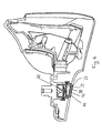
- Fig. 4 shows an embodiment according to FIG. 3, wherein the housing 18 as insert 31 has a reflector. It abuts the inner wall of the housing 18 and is provided with an opening 32 through which the LED 16 protrudes.
- the reflector 31 has a reflector surface 33 that reflects the light emitted by the LED 16 to the light window 10.
- the reflector 31 may be designed differently depending on the desired lighting effect, for example as a paraboloid. With its free edge, the reflector 31 is supported on an inner shoulder 34 of the housing 18, which is also provided in the housings according to FIGS. 2 and 3. The inner shoulder 34 is set back relative to the outer shoulder 24 inwards.
- the reflector 31 is also located on the board 17.
- the reflector 31 is preferably made of heat-resistant plastic.
- the ambient light 3 is the same design as that in the embodiment of FIG. 3rd
- the reflector 31 may also be formed as a heat-dissipating element. In this case, it consists of metallic material and is formed so that it has the shape of the lamp housing 18. The annular groove 20 is then provided on the outside of the reflector 31. In the free end of such a reflector then a lens is inserted. The heat generated by the LED 16 is derived in such a design not only on the carrier 17 in the support body 1 ', but also on the reflector 31 in the web 5.
- the board 17 of the ambient light 3, the heat generated by the LED 16 is also quickly and completely in the support body 1 'derived.
- Fig. 5 shows an embodiment in which the lamp housing 18 substantially corresponds to that of FIG. 3. Only the end face 25 of the central portion 22 of the light window 10 is concave according to the embodiment of FIG. 1.
- the inside of the light window 10 is provided with an optical structure 38 with which a targeted steering of the light emitted by the LED 16 light can be achieved.
- an optical element 39 is arranged, which is formed for example as a Fresnel lens.
- a lens 40 is housed in the housing 18.
- the optical elements 38 to 40 can of course also be installed in a different arrangement in the housing. It is also possible to use different combinations of these optical elements in order to achieve targeted steering of the light.
- the optical elements 38 to 40 are provided.
- the end face 25 of the light window 10 is provided with an optical structure 41.
- the light housing 18 may also be a light guide may be used or a combination of a light guide and the housing 18.
- the depth of the LED 16 can also be varied with a corresponding adjustment of the mirror base; to change the light field.
- the position of the ambient lighting 3 on the mirror 1, depending on which area is to be lit next to the vehicle and on the ground, can be changed arbitrarily.
- LED 16 instead of one LED 16, further LEDs, for example arranged in a row next to one another, may be provided in order to increase the light intensity.
- the described embodiments may in the exterior rearview mirror, in particular in the mirror head, bulbs as a repeater, transmitter and / or receiver of garage door openers, and / or navigation systems, sensors as part of the control of EC or LCD glass, antennas for car radios, compass and Like., Speakers and the like. Be installed. Also in the mirror other components can be provided, such as sender and / or receiver of garage door openers or navigation systems.
Landscapes
- Engineering & Computer Science (AREA)
- General Engineering & Computer Science (AREA)
- Mechanical Engineering (AREA)
- Multimedia (AREA)
- Lighting Device Outwards From Vehicle And Optical Signal (AREA)
- Rear-View Mirror Devices That Are Mounted On The Exterior Of The Vehicle (AREA)
Abstract
Claims (37)
- Rétroviseur extérieur pour véhicule, en particulier pour véhicule automobile, comportant un pied (1) à fixer sur le véhicule et sur lequel est fixée une tête rabattable, et comportant au moins un feu d'environnement (3) agencé dans le pied (1) et pourvu d'au moins un moyen lumineux (16), de préférence une diode électroluminescente, qui est agencé sur un support (17),
caractérisé en ce que le support (17) comprend un conducteur de chaleur métallique qui, dans le but de la dissipation de chaleur, prend appui directement contre un corps porteur (1'), dissipateur de chaleur, du pied (1). - Rétroviseur extérieur selon la revendication 1,
caractérisé en ce que le conducteur de chaleur est réalisé en forme de plaque. - Rétroviseur extérieur selon la revendication 1 ou 2,
caractérisé en ce que le conducteur de chaleur est agencé en renfoncement dans le support (17) qui est constitué de préférence par une carte à circuits imprimés. - Rétroviseur extérieur selon l'une des revendications 1 à 3,
caractérisé en ce que le moyen lumineux (16) forme une unité structurelle avec le support (17). - Rétroviseur extérieur selon l'une des revendications 1 à 4,
caractérisé en ce que sur le support (17) est agencé un boîtier de feu (18) recevant le moyen lumineux (16). - Rétroviseur extérieur selon la revendication 5,
caractérisé en ce que le boîtier de feu (18) présente une fenêtre à lumière (10). - Rétroviseur extérieur selon la revendication 5 ou 6,
caractérisé en ce que le boîtier de feu (18) est constitué d'un matériau résistant à la chaleur, de préférence de matière plastique. - Rétroviseur extérieur selon l'une des revendications 5 à 7,
caractérisé en ce que le boîtier de feu (18) et la fenêtre à lumière (10) sont réalisés d'un seul tenant. - Rétroviseur extérieur en particulier selon l'une des revendications 5 à 8,
caractérisé en ce que le boîtier de feu (18) est précontraint par rapport au support (17) dans la position montée, de telle sorte que le conducteur de chaleur du support (17) prend appui sous précontrainte contre les éléments du pied (1). - Rétroviseur extérieur selon l'une des revendications 5 à 9,
caractérisé en ce que le boîtier de feu (18) prend appui contre le pied (1) avec interposition d'au moins un joint d'étanchéité (21). - Rétroviseur extérieur selon la revendication 10,
caractérisé en ce que le joint (21) est un joint annulaire. - Rétroviseur extérieur selon la revendication 10 ou 11,
caractérisé en ce que le joint (21) se trouve dans une gorge annulaire (20). - Rétroviseur extérieur selon l'une des revendications 5 à 12,
caractérisé en ce que le boîtier de feu (18) est retenu avec blocage anti-rotation dans le pied (1). - Rétroviseur extérieur en particulier selon l'une des revendications 5 à 13,
caractérisé en ce que le boîtier de feu (18) est contraint contre le support (17) par un recouvrement (2) du pied (1), de telle sorte que le conducteur de chaleur du support (17) prend appui sous précontrainte contre les éléments du pied (1). - Rétroviseur extérieur selon la revendication 14,
caractérisé en ce que le recouvrement (2) est retenu sur le corps porteur (1') du pied (1) par l'intermédiaire d'une liaison à enclenchement, de préférence une liaison à encliquetage. - Rétroviseur extérieur selon la revendication 14 ou 15,
caractérisé en ce qu'un autre joint d'étanchéité (42) est agencé entre le recouvrement (2) et le boîtier de feu (18). - Rétroviseur extérieur selon l'une des revendications 6 à 16,
caractérisé en ce que la fenêtre à lumière (10) se transforme en la partie de boîtier restante via un épaulement extérieur (24). - Rétroviseur extérieur selon la revendication 17,
caractérisé en ce que le recouvrement (2) s'engage par une bordure (26) dans l'épaulement extérieur (24) du boîtier de feu (18). - Rétroviseur extérieur selon l'une des revendications 16 à 18,
caractérisé en ce que l'autre joint (42) se trouve dans un autre épaulement extérieur (43) du boîtier de feu (18). - Rétroviseur extérieur selon l'une des revendications 14 à 19,
caractérisé en ce que le boîtier de feu (18) est supporté sur le côté intérieur du recouvrement (2). - Rétroviseur extérieur selon l'une des revendications 5 à 20,
caractérisé en ce que le boîtier de feu (18) présente un renfoncement (28') sur son côté postérieur détourné de la fenêtre à lumière (10), renfoncement dans lequel pénètre le moyen lumineux (16) dans l'état monté du boîtier de feu. - Rétroviseur extérieur selon l'une des revendications 5 à 21,
caractérisé en ce que le boîtier de feu (18) est réalisé en forme de godet. - Rétroviseur extérieur selon l'une des revendications 5 à 22,
caractérisé en ce que le boîtier de feu (18) comprend une partie médiane (28). - Rétroviseur extérieur selon la revendication 23,
caractérisé en ce que la partie médiane (28) présente le renfoncement (28') pour recevoir le moyen lumineux (16). - Rétroviseur extérieur selon l'une des revendications 5 à 24,
caractérisé en ce qu'un réflecteur (31) est logé dans le boîtier de feu (18). - Rétroviseur extérieur selon la revendication 25,
caractérisé en ce que le moyen lumineux (16) pénètre dans le réflecteur (31). - Rétroviseur extérieur selon la revendication 25 ou 26,
caractérisé en ce que le réflecteur (31) repose sur le support (17). - Rétroviseur extérieur selon l'une des revendications 25 à 27,
caractérisé en ce que le réflecteur (31) prend appui sur un épaulement intérieur (34) du boîtier de feu (18). - Rétroviseur extérieur selon l'une des revendications 25 à 28,
caractérisé en ce que le réflecteur (31) est constitué d'un matériau résistant à la chaleur, de préférence de matière plastique. - Rétroviseur extérieur selon l'une des revendications 25 à 29,
caractérisé en ce que le réflecteur (31) est constitué d'un matériau dissipateur de chaleur, de préférence de métal. - Rétroviseur extérieur selon la revendication 30,
caractérisé en ce que le réflecteur (31) constitue une partie du boîtier de feu (8). - Rétroviseur extérieur selon l'une des revendications 5 à 31,
caractérisé en ce que le boîtier de feu (18) comprend au moins un, de préférence plusieurs éléments optiques (38 à 41). - Rétroviseur extérieur selon l'une des revendications 6 à 32,
caractérisé en ce que la fenêtre à lumière (10) se trouve dans une ouverture (9) du pied (1), en particulier du recouvrement (2). - Rétroviseur extérieur selon l'une des revendications 6 à 33,
caractérisé en ce que le côté frontal (22) de la fenêtre à lumière (10) constitue sensiblement un prolongement du côté extérieur du recouvrement (2). - Rétroviseur extérieur selon l'une des revendications 15 à 34,
caractérisé en ce que le corps porteur (1') du pied (1) présente un logement (4) pour le boîtier de feu (18). - Rétroviseur extérieur selon la revendication 35,
caractérisé en ce que le logement (4) est limité par des barrettes (5, 6) du corps porteur (1'). - Rétroviseur extérieur selon la revendication 35 ou 36,
caractérisé en ce que le support (17) prend appui par sa surface contre le fond (8) du logement (4) en étant chargé en pression par le boîtier de feu (18).
Applications Claiming Priority (3)
| Application Number | Priority Date | Filing Date | Title |
|---|---|---|---|
| DE10256197A DE10256197A1 (de) | 2002-12-02 | 2002-12-02 | Außenrückblickspiegel für Fahrzeuge, insbesondere Kraftfahrzeuge |
| DE10256197 | 2002-12-02 | ||
| PCT/DE2003/003904 WO2004050428A1 (fr) | 2002-12-02 | 2003-11-26 | Retroviseur exterieur destine a des vehicules |
Publications (2)
| Publication Number | Publication Date |
|---|---|
| EP1567390A1 EP1567390A1 (fr) | 2005-08-31 |
| EP1567390B1 true EP1567390B1 (fr) | 2007-01-10 |
Family
ID=32308906
Family Applications (1)
| Application Number | Title | Priority Date | Filing Date |
|---|---|---|---|
| EP03767450A Expired - Lifetime EP1567390B1 (fr) | 2002-12-02 | 2003-11-26 | Retroviseur exterieur destine a des vehicules |
Country Status (6)
| Country | Link |
|---|---|
| US (1) | US7682056B2 (fr) |
| EP (1) | EP1567390B1 (fr) |
| KR (1) | KR100946092B1 (fr) |
| AU (1) | AU2003291945A1 (fr) |
| DE (3) | DE10256197A1 (fr) |
| WO (1) | WO2004050428A1 (fr) |
Families Citing this family (18)
| Publication number | Priority date | Publication date | Assignee | Title |
|---|---|---|---|---|
| US7195382B1 (en) * | 2004-06-30 | 2007-03-27 | Magna Donnelly Mirrors North America, L.L.C. | Vehicle mirror with secondary lighting lens for ground illuminator |
| DE102005047189B4 (de) * | 2005-09-23 | 2013-03-07 | SMR Patents S.à.r.l. | Außenrückblickspiegel für Kraftfahrzeuge |
| US7404655B2 (en) * | 2006-05-10 | 2008-07-29 | Gentex Corporation | Vehicle rearview assembly including a map light |
| US20090086346A1 (en) * | 2007-10-01 | 2009-04-02 | Schefenacker Vision Systems Usa, Inc. | Side mirror assembly for a motor vehicle |
| DE102009019092A1 (de) * | 2009-04-20 | 2010-11-04 | SMR Patents S.à.r.l. | Minimaler LED Blinker im Außenspiegel |
| JP5734762B2 (ja) * | 2011-06-22 | 2015-06-17 | 株式会社東海理化電機製作所 | 車両用ミラー装置 |
| KR101218797B1 (ko) * | 2012-01-02 | 2013-01-04 | 주식회사 파인디앤씨 | 디스플레이 장치용 백라이트 유닛의 광원장치 |
| AT514405B1 (de) * | 2013-06-07 | 2015-05-15 | Zkw Slovakia S R O | Beleuchtungskörper für ein Fahrzeug |
| DE102016002575A1 (de) * | 2016-03-03 | 2017-09-07 | GM Global Technology Operations LLC (n. d. Ges. d. Staates Delaware) | Außenspiegelhalter |
| DE102017119542A1 (de) * | 2017-08-25 | 2019-02-28 | SMR Patents S.à.r.l. | Rückblickvorrichtung und Fahrzeug mit einer solchen Rückblickvorrichtung |
| US11305696B2 (en) | 2017-08-25 | 2022-04-19 | SMR Patents S.à.r.l. | Rearview device and vehicle with such rearview device |
| US10391929B1 (en) | 2018-08-20 | 2019-08-27 | Ficosa North America Corporation | Lighted path system for vehicle |
| JP7298094B2 (ja) * | 2019-09-09 | 2023-06-27 | 株式会社東海理化電機製作所 | 車両用投射装置及び車両用視認装置 |
| CN212929936U (zh) * | 2020-08-20 | 2021-04-09 | 肯舒摩照明(美国)有限责任公司 | 感测装置和照明装置 |
| CN113776022B (zh) * | 2021-11-15 | 2022-02-11 | 深圳市金风驰科技有限公司 | 一种摩托车照明装置 |
| US12377781B2 (en) * | 2022-04-14 | 2025-08-05 | Magna Exteriors, Inc. | Integrated in-surface lens assembly |
| US20230331149A1 (en) | 2022-04-14 | 2023-10-19 | Magna Exteriors Inc. | Integrated in-surface lens assembly |
| JP2024158524A (ja) * | 2023-04-27 | 2024-11-08 | 美里工業株式会社 | 車両用ドアミラー及びその製造方法 |
Family Cites Families (25)
| Publication number | Priority date | Publication date | Assignee | Title |
|---|---|---|---|---|
| US1223981A (en) * | 1916-02-08 | 1917-04-24 | Axel W Johnson | Automobile signaling device. |
| US1381561A (en) * | 1919-08-21 | 1921-06-14 | Johnson Samuel Sylvester | Signal device or indicator |
| US1368644A (en) * | 1920-05-12 | 1921-02-15 | Jack K Mochizuki | Signaling device |
| US1814728A (en) * | 1930-06-05 | 1931-07-14 | Moore George | Combined rear view mirror and parking light for automobiles |
| US2595331A (en) * | 1950-01-30 | 1952-05-06 | Paul F Calihan | Combination vision mirror and signaling device |
| US4211955A (en) * | 1978-03-02 | 1980-07-08 | Ray Stephen W | Solid state lamp |
| US5017903C1 (en) * | 1989-02-21 | 2002-08-13 | Jacob Krippelz Sr | Emergency light |
| US5014167A (en) * | 1990-02-20 | 1991-05-07 | K. W. Muth Company, Inc. | Visual signaling apparatus |
| US5160200A (en) * | 1991-03-06 | 1992-11-03 | R & D Molded Products, Inc. | Wedge-base LED bulb housing |
| US5669699A (en) * | 1994-11-02 | 1997-09-23 | Donnelly Corporation | Exterior vehicle security light |
| US5660457A (en) * | 1995-11-07 | 1997-08-26 | Whelen Engineering Company, Inc. | Integrated warning light and rear-view mirror |
| US6152590A (en) * | 1998-02-13 | 2000-11-28 | Donnelly Hohe Gmbh & Co. Kg | Lighting device for motor vehicles |
| US6572250B1 (en) * | 1999-03-15 | 2003-06-03 | Britax Wingard Limited | Exterior mirror having an attachment member including an approach light |
| US6371636B1 (en) * | 1999-05-24 | 2002-04-16 | Jam Strait, Inc. | LED light module for vehicles |
| US6049271A (en) * | 1999-06-29 | 2000-04-11 | Chu; Ching-Ti | Vehicle rearview mirror with multiple signal means |
| US6227689B1 (en) * | 1999-09-28 | 2001-05-08 | Donnelly Corporation | Illumination device for exterior mirror |
| AU2001238087A1 (en) * | 2000-02-11 | 2001-08-20 | Britax Vision Systems (North America) Inc. | Exterior mirror |
| ES2168071B1 (es) | 2000-07-12 | 2003-07-16 | Barros Alejandro Rodriguez | Retrovisor modular con señales multiples intercambiables para vehiculos de 2, 3, 4 o mas ruedas. |
| US6357902B1 (en) * | 2000-09-25 | 2002-03-19 | Brian Horowitz | After market LED taillight bulb |
| WO2002062623A2 (fr) * | 2001-01-23 | 2002-08-15 | Donnelly Corporation | Systeme d'eclairage ameliore destine a un vehicule |
| EP1421316B1 (fr) * | 2001-08-31 | 2007-10-17 | Gentex Corporation | Ensemble lampe de vehicule avec dissipateur de chaleur |
| US6827468B2 (en) * | 2001-12-10 | 2004-12-07 | Robert D. Galli | LED lighting assembly |
| US20040022064A1 (en) * | 2002-07-31 | 2004-02-05 | Fang-Mei Kuo | Lamp for the rear-view mirror of a vehicle |
| DE10308073A1 (de) * | 2003-02-26 | 2004-09-09 | Schefenacker Vision Systems Germany Gmbh & Co. Kg | Außenrückblickspiegel für Fahrzeuge, vorzugsweise für Kraftfahrzeuge |
| US7195382B1 (en) * | 2004-06-30 | 2007-03-27 | Magna Donnelly Mirrors North America, L.L.C. | Vehicle mirror with secondary lighting lens for ground illuminator |
-
2002
- 2002-12-02 DE DE10256197A patent/DE10256197A1/de not_active Withdrawn
-
2003
- 2003-11-26 DE DE10394128T patent/DE10394128D2/de not_active Expired - Fee Related
- 2003-11-26 WO PCT/DE2003/003904 patent/WO2004050428A1/fr not_active Ceased
- 2003-11-26 EP EP03767450A patent/EP1567390B1/fr not_active Expired - Lifetime
- 2003-11-26 US US10/537,165 patent/US7682056B2/en not_active Expired - Fee Related
- 2003-11-26 AU AU2003291945A patent/AU2003291945A1/en not_active Abandoned
- 2003-11-26 KR KR1020047019576A patent/KR100946092B1/ko not_active Expired - Fee Related
- 2003-11-26 DE DE50306279T patent/DE50306279D1/de not_active Expired - Lifetime
Also Published As
| Publication number | Publication date |
|---|---|
| AU2003291945A1 (en) | 2004-06-23 |
| DE10256197A1 (de) | 2004-06-09 |
| EP1567390A1 (fr) | 2005-08-31 |
| US20060133101A1 (en) | 2006-06-22 |
| DE50306279D1 (de) | 2007-02-22 |
| KR100946092B1 (ko) | 2010-03-10 |
| US7682056B2 (en) | 2010-03-23 |
| WO2004050428A1 (fr) | 2004-06-17 |
| DE10394128D2 (de) | 2005-10-27 |
| KR20050088261A (ko) | 2005-09-05 |
Similar Documents
| Publication | Publication Date | Title |
|---|---|---|
| EP1567390B1 (fr) | Retroviseur exterieur destine a des vehicules | |
| EP1598237B1 (fr) | Rétroviseur extérieur de véhicule | |
| EP0858932B2 (fr) | Rétroviseur extérieur de véhicules, en particulier à moteur | |
| US7434962B2 (en) | Low-profile, aimable lighting assembly | |
| EP1232910B1 (fr) | Feu de véhicule | |
| DE19805771A1 (de) | Beleuchtungseinrichtung für Kraftfahrzeuge | |
| DE102005013682B4 (de) | Außenrückblickspiegel von Fahrzeugen, vorzugsweise von Kraftfahrzeugen | |
| EP1120312A2 (fr) | Rétroviseur extérieur de véhicule, en particulier de véhicule automobile | |
| EP1757487A1 (fr) | Rétroviseur extérieur pour véhicules | |
| EP3844028A1 (fr) | Dispositif d'éclairage destiné à un véhicule automobile | |
| WO2005113291A1 (fr) | Rétroviseur externe pour véhicules, en particulier pour véhicules à moteur | |
| EP0745511A2 (fr) | Dispositif d'éclairage pour véhicule | |
| DE102007010747A1 (de) | Außenrückblickspiegel für Fahrzeuge, insbesondere Kraftfahrzeuge | |
| EP2651695A1 (fr) | Dispositif d'éclairage intérieur dans un véhicule automobile | |
| EP2239498B1 (fr) | Lampe dotée d'une lèvre d'étanchéité sur la circonférence | |
| DE19546271B4 (de) | Scheinwerfer für Fahrzeuge mit einem verschwenkbaren Reflektor | |
| DE102011118219A1 (de) | Leuchteinrichtung für ein Kraftfahrzeug | |
| DE10339833B4 (de) | Beleuchtetes Stellrad | |
| EP1597112B1 (fr) | Retroviseur exterieur pour vehicules automobiles | |
| DE102005012104A1 (de) | Gehäuse, insbesondere Spiegelgehäuse | |
| EP1964720B1 (fr) | Rétroviseur extérieur pour véhicules, de préférence pour véhicules automobiles | |
| EP2828125B1 (fr) | Système destiné à fournir un dispositif permettant d'éclairer l'habitable d'un véhicule et procédé destiné à fabriquer un tel système | |
| DE102015119445A1 (de) | Verfahren zur Herstellung einer Designeinrichtung für Fahrzeuge sowie Beleuchtungsvorrichtung | |
| DE102011113184B4 (de) | Rückspiegelgehäuseeinheit für einen Fahrzeugaußenspiegel | |
| DE102018222335B4 (de) | Kraftfahrzeugscheinwerfer sowie Kraftfahrzeug |
Legal Events
| Date | Code | Title | Description |
|---|---|---|---|
| PUAI | Public reference made under article 153(3) epc to a published international application that has entered the european phase |
Free format text: ORIGINAL CODE: 0009012 |
|
| 17P | Request for examination filed |
Effective date: 20050203 |
|
| AK | Designated contracting states |
Kind code of ref document: A1 Designated state(s): AT BE BG CH CY CZ DE DK EE ES FI FR GB GR HU IE IT LI LU MC NL PT RO SE SI SK TR |
|
| AX | Request for extension of the european patent |
Extension state: AL LT LV MK |
|
| DAX | Request for extension of the european patent (deleted) | ||
| RBV | Designated contracting states (corrected) |
Designated state(s): DE FR GB |
|
| GRAP | Despatch of communication of intention to grant a patent |
Free format text: ORIGINAL CODE: EPIDOSNIGR1 |
|
| GRAS | Grant fee paid |
Free format text: ORIGINAL CODE: EPIDOSNIGR3 |
|
| GRAA | (expected) grant |
Free format text: ORIGINAL CODE: 0009210 |
|
| RAP1 | Party data changed (applicant data changed or rights of an application transferred) |
Owner name: SCHEFENACKER VISION SYSTEMS GERMANY GMBH |
|
| AK | Designated contracting states |
Kind code of ref document: B1 Designated state(s): DE FR GB |
|
| REG | Reference to a national code |
Ref country code: GB Ref legal event code: FG4D Free format text: NOT ENGLISH |
|
| REF | Corresponds to: |
Ref document number: 50306279 Country of ref document: DE Date of ref document: 20070222 Kind code of ref document: P |
|
| GBT | Gb: translation of ep patent filed (gb section 77(6)(a)/1977) |
Effective date: 20070425 |
|
| ET | Fr: translation filed | ||
| PLBE | No opposition filed within time limit |
Free format text: ORIGINAL CODE: 0009261 |
|
| STAA | Information on the status of an ep patent application or granted ep patent |
Free format text: STATUS: NO OPPOSITION FILED WITHIN TIME LIMIT |
|
| 26N | No opposition filed |
Effective date: 20071011 |
|
| REG | Reference to a national code |
Ref country code: GB Ref legal event code: 732E Free format text: REGISTERED BETWEEN 20090219 AND 20090225 |
|
| REG | Reference to a national code |
Ref country code: FR Ref legal event code: CD Ref country code: FR Ref legal event code: TP Ref country code: FR Ref legal event code: CA |
|
| REG | Reference to a national code |
Ref country code: DE Ref legal event code: R082 Ref document number: 50306279 Country of ref document: DE Representative=s name: JONES DAY RECHTSANWAELTE PATENTANWAELTE, DE |
|
| PGFP | Annual fee paid to national office [announced via postgrant information from national office to epo] |
Ref country code: FR Payment date: 20121130 Year of fee payment: 10 Ref country code: DE Payment date: 20121121 Year of fee payment: 10 |
|
| PGFP | Annual fee paid to national office [announced via postgrant information from national office to epo] |
Ref country code: GB Payment date: 20121120 Year of fee payment: 10 |
|
| GBPC | Gb: european patent ceased through non-payment of renewal fee |
Effective date: 20131126 |
|
| REG | Reference to a national code |
Ref country code: FR Ref legal event code: ST Effective date: 20140731 |
|
| REG | Reference to a national code |
Ref country code: DE Ref legal event code: R119 Ref document number: 50306279 Country of ref document: DE Effective date: 20140603 |
|
| PG25 | Lapsed in a contracting state [announced via postgrant information from national office to epo] |
Ref country code: DE Free format text: LAPSE BECAUSE OF NON-PAYMENT OF DUE FEES Effective date: 20140603 |
|
| PG25 | Lapsed in a contracting state [announced via postgrant information from national office to epo] |
Ref country code: FR Free format text: LAPSE BECAUSE OF NON-PAYMENT OF DUE FEES Effective date: 20131202 Ref country code: GB Free format text: LAPSE BECAUSE OF NON-PAYMENT OF DUE FEES Effective date: 20131126 |