EP1567352B1 - Parallel-tintenstrahldruckgerät und herstellungsverfahren - Google Patents
Parallel-tintenstrahldruckgerät und herstellungsverfahren Download PDFInfo
- Publication number
- EP1567352B1 EP1567352B1 EP03772640A EP03772640A EP1567352B1 EP 1567352 B1 EP1567352 B1 EP 1567352B1 EP 03772640 A EP03772640 A EP 03772640A EP 03772640 A EP03772640 A EP 03772640A EP 1567352 B1 EP1567352 B1 EP 1567352B1
- Authority
- EP
- European Patent Office
- Prior art keywords
- modules
- ink
- ejection
- chambers
- parallel
- Prior art date
- Legal status (The legal status is an assumption and is not a legal conclusion. Google has not performed a legal analysis and makes no representation as to the accuracy of the status listed.)
- Expired - Lifetime
Links
- 238000007641 inkjet printing Methods 0.000 title claims description 17
- 238000004519 manufacturing process Methods 0.000 title claims description 15
- 238000007639 printing Methods 0.000 claims abstract description 50
- 238000010438 heat treatment Methods 0.000 claims abstract description 9
- 239000000463 material Substances 0.000 claims abstract description 5
- 238000000034 method Methods 0.000 claims description 12
- 230000008569 process Effects 0.000 claims description 5
- 239000000853 adhesive Substances 0.000 claims description 4
- 230000001070 adhesive effect Effects 0.000 claims description 4
- 239000003086 colorant Substances 0.000 claims description 4
- 238000006116 polymerization reaction Methods 0.000 claims 1
- 230000001360 synchronised effect Effects 0.000 claims 1
- 238000005476 soldering Methods 0.000 description 8
- PNEYBMLMFCGWSK-UHFFFAOYSA-N Alumina Chemical compound [O-2].[O-2].[O-2].[Al+3].[Al+3] PNEYBMLMFCGWSK-UHFFFAOYSA-N 0.000 description 6
- 238000004026 adhesive bonding Methods 0.000 description 4
- 239000010408 film Substances 0.000 description 4
- 239000011347 resin Substances 0.000 description 4
- 229920005989 resin Polymers 0.000 description 4
- 239000000919 ceramic Substances 0.000 description 3
- 229910021419 crystalline silicon Inorganic materials 0.000 description 3
- 238000005516 engineering process Methods 0.000 description 3
- 230000010355 oscillation Effects 0.000 description 3
- 239000000758 substrate Substances 0.000 description 3
- 235000012431 wafers Nutrition 0.000 description 3
- PXHVJJICTQNCMI-UHFFFAOYSA-N Nickel Chemical compound [Ni] PXHVJJICTQNCMI-UHFFFAOYSA-N 0.000 description 2
- XUIMIQQOPSSXEZ-UHFFFAOYSA-N Silicon Chemical compound [Si] XUIMIQQOPSSXEZ-UHFFFAOYSA-N 0.000 description 2
- 238000010276 construction Methods 0.000 description 2
- 230000008021 deposition Effects 0.000 description 2
- 238000010586 diagram Methods 0.000 description 2
- 238000003754 machining Methods 0.000 description 2
- 238000003825 pressing Methods 0.000 description 2
- 229910052710 silicon Inorganic materials 0.000 description 2
- 239000010703 silicon Substances 0.000 description 2
- 238000012360 testing method Methods 0.000 description 2
- RYGMFSIKBFXOCR-UHFFFAOYSA-N Copper Chemical compound [Cu] RYGMFSIKBFXOCR-UHFFFAOYSA-N 0.000 description 1
- 238000010521 absorption reaction Methods 0.000 description 1
- 230000004913 activation Effects 0.000 description 1
- 230000015572 biosynthetic process Effects 0.000 description 1
- 239000005388 borosilicate glass Substances 0.000 description 1
- 238000003486 chemical etching Methods 0.000 description 1
- 230000000295 complement effect Effects 0.000 description 1
- 229910052802 copper Inorganic materials 0.000 description 1
- 239000010949 copper Substances 0.000 description 1
- 230000008878 coupling Effects 0.000 description 1
- 238000010168 coupling process Methods 0.000 description 1
- 238000005859 coupling reaction Methods 0.000 description 1
- 238000005520 cutting process Methods 0.000 description 1
- 230000007547 defect Effects 0.000 description 1
- 238000006073 displacement reaction Methods 0.000 description 1
- 238000005323 electroforming Methods 0.000 description 1
- 238000000605 extraction Methods 0.000 description 1
- 238000011049 filling Methods 0.000 description 1
- 238000001914 filtration Methods 0.000 description 1
- 238000010304 firing Methods 0.000 description 1
- PCHJSUWPFVWCPO-UHFFFAOYSA-N gold Chemical compound [Au] PCHJSUWPFVWCPO-UHFFFAOYSA-N 0.000 description 1
- 239000010931 gold Substances 0.000 description 1
- 229910052737 gold Inorganic materials 0.000 description 1
- 230000004886 head movement Effects 0.000 description 1
- 238000007689 inspection Methods 0.000 description 1
- 238000002372 labelling Methods 0.000 description 1
- 229910052751 metal Inorganic materials 0.000 description 1
- 239000002184 metal Substances 0.000 description 1
- 238000000465 moulding Methods 0.000 description 1
- 229910052759 nickel Inorganic materials 0.000 description 1
- 239000004033 plastic Substances 0.000 description 1
- 229920000642 polymer Polymers 0.000 description 1
- 238000002360 preparation method Methods 0.000 description 1
- 230000009467 reduction Effects 0.000 description 1
- 239000002990 reinforced plastic Substances 0.000 description 1
- 230000000284 resting effect Effects 0.000 description 1
- 238000005488 sandblasting Methods 0.000 description 1
- 238000007789 sealing Methods 0.000 description 1
- 239000004065 semiconductor Substances 0.000 description 1
- 239000010409 thin film Substances 0.000 description 1
Images

Classifications
-
- B—PERFORMING OPERATIONS; TRANSPORTING
- B41—PRINTING; LINING MACHINES; TYPEWRITERS; STAMPS
- B41J—TYPEWRITERS; SELECTIVE PRINTING MECHANISMS, i.e. MECHANISMS PRINTING OTHERWISE THAN FROM A FORME; CORRECTION OF TYPOGRAPHICAL ERRORS
- B41J2/00—Typewriters or selective printing mechanisms characterised by the printing or marking process for which they are designed
- B41J2/005—Typewriters or selective printing mechanisms characterised by the printing or marking process for which they are designed characterised by bringing liquid or particles selectively into contact with a printing material
- B41J2/01—Ink jet
- B41J2/135—Nozzles
- B41J2/14—Structure thereof only for on-demand ink jet heads
- B41J2/14016—Structure of bubble jet print heads
- B41J2/14024—Assembling head parts
-
- B—PERFORMING OPERATIONS; TRANSPORTING
- B41—PRINTING; LINING MACHINES; TYPEWRITERS; STAMPS
- B41J—TYPEWRITERS; SELECTIVE PRINTING MECHANISMS, i.e. MECHANISMS PRINTING OTHERWISE THAN FROM A FORME; CORRECTION OF TYPOGRAPHICAL ERRORS
- B41J2/00—Typewriters or selective printing mechanisms characterised by the printing or marking process for which they are designed
- B41J2/005—Typewriters or selective printing mechanisms characterised by the printing or marking process for which they are designed characterised by bringing liquid or particles selectively into contact with a printing material
- B41J2/01—Ink jet
- B41J2/135—Nozzles
- B41J2/145—Arrangement thereof
-
- B—PERFORMING OPERATIONS; TRANSPORTING
- B41—PRINTING; LINING MACHINES; TYPEWRITERS; STAMPS
- B41J—TYPEWRITERS; SELECTIVE PRINTING MECHANISMS, i.e. MECHANISMS PRINTING OTHERWISE THAN FROM A FORME; CORRECTION OF TYPOGRAPHICAL ERRORS
- B41J2202/00—Embodiments of or processes related to ink-jet or thermal heads
- B41J2202/01—Embodiments of or processes related to ink-jet heads
- B41J2202/20—Modules
Definitions
- This invention relates to parallel type, ink jet printing devices. More specifically, the invention relates to an ink jet printing device with a parallel type or serial-parallel type head comprising a plurality of ejection modules in accordance with the introductorypart of claim 1.
- the invention has been developed with particular regard for application on a device in which heat energy is used to produce vapour bubbles in chambers filled with ink, resulting in the ejection of droplets of ink through relative nozzles.
- Thermal type ink jet printing devices use heads having ejection modules which are usually made from wafers of semiconducting material with technologies similar to those employed for producing integrated and/or hybrid circuits. This means that the heating elements and relative driving circuits, together with the hydraulic, ink feeding network, can be obtained, all within extremely reduced dimensions.
- the ink jet technology is also suitable for the production of printing devices having parallel or serial-parallel type heads with printing of the entire line of a page in a single run, that is without any scanning movement of the head over the surface being printed on or with a movement that is restricted to a fraction of the line.
- the printing devices with heads that operate in parallel or serial-parallel are of compact dimensions and enable printers of great simplicity and limited encumbrance height-wise to be produced. Their field of application thus extends to sectors which include, inter alia, the printing of cash slips, labelling, printing in measuring equipment and photographic printing, as described for example in patent application No. TO2001A000707, filed on 19 July 2001 by the Applicant (see also WO-A-008195 ).
- one proposal has been the recourse to heads with numerous elementary ejection modules of compact dimensions, assembled in such a way as to give a disposition of nozzles aligned in a common direction as in a single module, of the same length as the printing width.
- the modules are stuck side by side, with pitch between the nozzles being maintained constant. This also applies to the last nozzle and the first nozzle of two adjacent units.
- other problems arise from using this structure such as, for instance, that of the impossibility of using modules in which feeding of the ink occurs through common slots.
- patent US-A-6,068,367 discloses a parallel ink jet printing device comprising a plurality of modules on a frame.
- the modules are capable to be inserted in corresponding openings formed in the frame and are provided with an associated reservoir having a tubular structure.
- Patent application EP-A-0816085 discloses, inter alia, an ink jet apparatus wherein, in one embodiment, an elongated head including a plurality of chip elements or modules are aligned to provide many numbers of discharge ports along one line.
- Patent US-A-6,137,506 discloses an ink jet recording head comprising a substrate having a plurality of thermal generating means and a plurality of orifice plates.
- the orifice plates are attached to the substrate so that the orifices are disposed above the plurality of thermal generating means and each orifice plate is separated from any other by oblique transverse slits in order to compensate a different thermal expansion between the substrate and the orifice plates.
- US-A-6,155,669 discloses a parallel printing head having a print-bar including a plurality of nozzles aligned perpendicular to a recording medium path.
- a recording medium transport is arranged to move the recording medium along the recording medium path.
- ink jet devices with heads operating in parallel, having ejection modules and nozzles in a staggered arrangement. This, however, gives rise to a worsening of the alignment of the dots in the printing phase and a more complex logic for controlling activation of the nozzles and in the associated circuitry.
- the main object of this invention consists in producing ink jet printing devices having parallel or serial-parallel type heads, without the drawbacks mentioned above and which can be made with low production times and costs.
- Another object of the invention is that of defining a process for the production of ink jet printing devices with parallel or serial-parallel type heads, in which there is feeding of the ink into the ejection chambers through common ducts or slots, produced on a low-cost support and with little precision, which do not interfere with the integrity and robustness of the ejection modules and associated functional components.
- Yet another object of the invention is that of providing an ink jet printing device with nozzles arranged in a line in a direction parallel to the printing axis, of low dimensions and cost and which guarantees a good printing resolution.
- a further object of the invention is to produce a colour ink jet printing device, with parallel or serial-parallel heads of compact dimensions and at low cost.
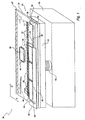
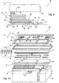
- FIG. 1 Depicted in figure 1 , and designated with the numeral 20, in an upside-down position, is an ink jet printing device according to the invention for a printer not shown in any of the figures, with reference to an axis "X" parallel to the line of print and to an axis "Y" in the direction of feeding of the print medium.
- the device 20 employs a head 21 of the serial-parallel type having a row of nozzles which extends in a main direction parallel to the line of printing of a page and in which the nozzles eject droplets of ink on an elementary line of printing.
- the head 21 comprises a plurality of ejection modules 22, arranged in a row, aligned among one another and parallel to the "X" axis ( Fig. 3 ).
- Each module 22 is provided with respective ejection chambers 23 ( Figs. 4 , 5 and 6 ) suitable for containing ink and with associated relative heating elements or resistors 24, with a "topshooter” type architecture for control of the function of ejecting ink on a sheet 26.
- the head 21 ( Figs.1 , 2 , 4 and 6 ) comprises a support including a base plate 27 for the modules 22 and hydraulic tight means between the modules 22 and the support.
- the tight means encloses a lamina which extends parallel to the "X" axis in the embodiment described herein.
- the ejection nozzles indicated with 32 are obtained in the same lamina, defined as nozzle plate 28, and are disposed along a line which extends parallel to the "X" axis.
- a chip driver 29, for selection and driving of the modules 22, and an auxiliary tank 31 for the ink are also included.
- the support, the nozzle plate 28 and the tank 31 are common for all the modules 22 of the row and extend parallel to the "X" axis.
- the plate 27 is of rigid and isolating material and acts as a support for the modules 22.
- the plate 27 includes a feeding duct for the ink defined by a slot-shaped aperture 33 which passes through the thickness of the plate itself and is connected to the tank 31.
- the chip driver 29 On the plate, behind the row of modules 22 in the direction of the "Y" axis, is mounted the chip driver 29. According to known techniques, the selection and driving functions may, alternatively, be handled by integrated circuits in the individual modules 22.
- the ejection modules 22 are mounted side by side on the plate 27, with the chambers 23 in hydraulic, tight connection with the aperture 33.
- the plate 28 is mounted on the modules 22 and constitutes a hydraulically tight upper cover for them, for the chambers 23 and in which the nozzles 32 are in hydraulic, tight connection with corresponding chambers 23 of the modules 22.
- the idea of the solution according to this invention is that of constructing the printing device 20 using a head 21 with a plurality of ejection modules 22, having sides 37 and 38 of reduced dimensions (along the Y axis), that are simple to produce and that are assembled together at the end of their respective machining processes.
- the plate 27 extends substantially for the length of the printing line of the sheet 26 and the slot-shaped aperture 33 extends along the plate, also for the length of the printing line along the "X" axis, adjacent to a front thereof.
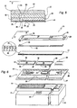
- Each module 22 consists of a rectangular shaped die 34 of crystalline silicon, with a front of greater length 36 and sides 37 and 38. Using known processes, the active components constituting the selections circuits are made on the die 34. Made next are the layers relative to the heating elements or resistors 24, the relative interconnections, not shown in any figures, and I/O pads 39 and a photosensitive resin film 41 in which the ink ejection chambers 23, aligned with the corresponding heating elements or resistors 24, and the feeding ducts 35 are made ( Figs. 5 and 6 ).
- the various ejection modules 22, for the length associated with the line of print, are mounted on the base plate 27 by gluing and pressing.
- the modules are disposed with the fronts of greater length 36 aligned among each other and parallel to the "X" axis ( Fig. 3 ).
- the head 21 is completed with the application, above the frame 42 and the modules 22, of the plate 28, the ejection nozzles 32 of which are exactly facing the ejection chambers 23 and the respective resistors 24, in such a way that the ink droplets are ejected on the sheet 26 ( Fig. 2 ) in a direction perpendicular to the plane of the nozzle plate 28.
- the ejection modules 22 have, for example, a width of 1.5-2.5 mm and a length of 8.4 mm (1/3") or 12.4 mm (1/2") or greater, and may be made from a wafer of crystalline silicon, not shown in any of the drawings, of thickness between 400 and 600 ⁇ m. In detail, from a disk of 6", approximately 700 modules may be made, net of any production rejects.
- the chambers 23 and the resistors 24 are arranged parallel to the front 36 adjacent to the edge, the I pads /O 39 along the opposite front and the active components in the central part.
- the logic circuits for selection, the resistors 24, the ejection chambers, the I/O pads, the internal interconnections and those for the ink may be obtained, following construction processes known in the art, as described for instance in Italian patent No. 1.234.800 , or in Italian patent application No. TO2001A001019 filed by the applicant, which are cited for reference.
- the chambers 23 and the resistors 24 have pitch "P" equal to the pitch of the nozzles 32, whereas the distances between the sides 37 and 38 and the axes of the terminal chambers 23 are slightly less than "0.5 P", so as to allow, during assembly on the plate 27, a space “G” to be left between the sides 37 and 38 of two adjacent modules 22, ensuring alignment and constancy of the pitch "P" between the chambers of the two modules.
- the modules 22 are separated by cutting of the disc, according to a rectangular grid of dimensions conforming to the dimensions of the individual modules.
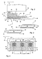
- the base plate 27 ( Fig. 5 ) is substantially rectangular, delimited by opposite, flat and parallel surfaces.
- the plate 27 may be cut by a rigid, electrically isolating, chemically inert sheet, with coefficient of thermal expansion close to that of the crystalline silicon, such as aluminium oxide or borosilicate glass.
- the material may be silicon of the type known commercially as "reworked”, without any special electrical or mechanical characteristics, however it is also possible to use a thermally stabilized, ceramic-coated, reinforced plastic metal (PCB).
- PCB thermally stabilized, ceramic-coated, reinforced plastic metal
- the slot-shaped aperture 33 may be obtained without any restrictions on precision as it has no delicate components. It can be made with any one of the methods known in the sector art, such as sand blasting, laser beam, vacuum plasma, chemical etching, etc. In the case of aluminium oxide or ceramic, the slot can be obtained by moulding before firing.
- soldering pads 43 and 44 are made on the base plate 27 in which to create soldering pads 43 and 44, interconnection tracks 46 (depicted merely by way of example) and I/O pads 47.
- the pads 43 and 44 concern the connections to the I/O pads 39 of the modules 22 and the soldering with the terminals of the chip driver 29, and the I/O pads 47 are provided for connection of the device 20 with cables of the printer, not shown in any of the figures.
- the pads 43, 44 and 47 and the interconnection tracks 46 may be of thick film or thin film if the support is ceramic or of gold plated copper in the case of a plastic support (PCB).
- the counterpart 42 comprises a substantially rectangular shaped resin frame of the same thickness as the module 22 and having a central aperture 48, also rectangular shape.
- the aperture 48 is complementary to the overall dimension of all the ejection modules 22 parallel to the fronts 36 and such as to partially or totally border the side 37 of the first module and the side 38 of the last module 22.
- the counterpart or frame 42 is at a distance from the fronts 36 in such a way as to form a passage for the ink 50 communicating with the slot 33 and, through the feeding channels 35 made with the photosensitive film 41, with the ejection chambers 23.
- the thickness of the counterpart 42 ensures that the respective upper surfaces form a flat surface, thus facilitating tight gluing of the nozzle plate 28 ( Fig.5 ).
- the nozzle plate 28 is made of Kapton TM and, as well as the nozzles 32, also includes slots 49 which, during the assembly stage, are in correspondence with junctions in the sides of the modules 22 and in the heads, and are filled with resin to obtain a hydraulic seal.
- the plate 28 can be made from a tape etched by laser, leaving support appendages. Alternatively, the plate 28 may be obtained by electroforming of a thin metallic sheet of gold-plated nickel.
- the auxiliary tank 31 is defined by a hollow body of parallelepiped shape, of the same length as the aperture 33 and arranged on the surface of the plate 27 opposite that on which the modules 22 are mounted.
- the tank 31, internally, has a well-known sponge type filling 51, is in hydraulic, tight connection with the aperture 33 and can be filled with ink for testing functionality of the head 21.
- the device 20 also comprises, associated with the head 20, a main ink cartridge 53, removable type, suitable for connection with the tank 31 through an elastic joint filter 52.
- the joint filter 52 acts as a mechanical decoupling between head 21 and cartridge 53 and tight, filtering coupling in relation to the cartridge 53.
- Assembly of the device 20, for the head 21 entails a step in which the modules 22 are mounted on the base plate 27. More specifically, the modules are positioned respecting the alignment, shown in figures 4 and 5 , of the edges 36 facing the slot-shaped aperture 33 and stuck hydraulically tight by means of a polymerizable adhesive.
- the counterpart or frame 42 is positioned and then stuck on the plate 27, with the top part coplanar with the upper surface of the modules 22 defining, together with the edges 36, the passage for the ink 50 facing the slot-shaped aperture 33.
- the slots 49 are then filled with resin in correspondence with the spaces between the various components, guaranteeing that they are mechanically and hydraulically sealed.
- the auxiliary tank 31 is fixed tight on the plate 27, in connection with the slot-shaped aperture 33.
- the preparation of the base plate 27 is completed with electrical connection (wire bonding) of the I/O pads 39 of the modules 22 with the soldering pads 43 of the base plate 27 and with the soldering of the chip driver 29 to the pads 44.
- a flat cable is connected to the device 20, produced as described, by soldering of its ends to the I/O pads 47.
- the elastic joint filter 52 and the flat cable allow the whole consisting of the modules 22 and the base plate 27 to move transversally with respect to the sheet 26, while keeping the cartridge 53 still.
- the device 20 of the invention can be used in a printer in which the transversal oscillating movement is impressed on the sheet, while the relative head remains still.
- the cartridge 53 may be replaced periodically with arrangements similar to those adopted for replacement of the ink cartridges, provided with refill capability, in serial printing devices.
- FIG. 7 Shown in figure 7 is a colour printing group, designated with the numeral 54, in which three heads 21a, 21b and 21c similar to the head 21 of the device 20 are assembled on a single plate 56, each with a row of modules 22, relative counterpart 42 and the nozzle plate 28, for three relative ink cartridges 57a, 57b and 57c with the fundamental colours and through three auxiliary tanks 31.
- the modules 22 of each row are aligned parallel to the "X" axis and the three heads are arranged one behind the other along the "Y" axis.
- the modules 22 are active type with integrated selection circuits, to minimize the number of interconnection tracks.
- the plate 56 is of the same length on the "X" axis as the plate 27 of Fig. 6 and has three slot-shaped apertures 58a, 58b and 58c, each identical to the aperture 33 and having the purpose of feeding the three rows of modules 22 with the ink of the cartridges.
- the width of the group 54 on the "X" axis and the overall height are substantially determined by the dimensions and therefore by the effective capacity of the cartridges 57a, 57b and 57c.
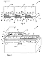
- the head 73 also has the ejection modules 22 aligned with the row of nozzles 32 arranged in a single line parallel to the line of printing, and therefore the "X" axis. These modules are fed from the auxiliary tank 31 and are driven by the chip driver 29.
- the head 73 has a base plate, indicated with 62 for assembly of the modules 22, a frame 63 and a nozzle plate 64.
- the plate 62 defines the support element for the modules 22 and the lamina 64 defines the row of ejection nozzles 32.
- the plate 62 is made of the same material as the plate 27 of Fig. 6 and includes the slot-shaped aperture 33 connected to the tank 31, but is without the metallic conducting layers.
- the ejection modules 22 are mounted on the plate 62 and the frame 63 has an aperture 65 that completely surrounds the modules 22.
- the nozzle plate 64 is mounted on the modules 22 and on the frame 63 and its nozzles 32 are hydraulically connected to the chambers 23 of the modules 22.
- the plate 64 extends width-wise along the "Y" axis beyond the I/O pads 39 and is provided with a slot 66 above the pads 39, an aperture 70 for accommodating the chip driver 29 and soldering tabs 67 and 68, respectively for the connections to the I/O pads 39 and for the soldering with the terminals of the chip driver 29, interconnection tracks 69 and I/O pads 71.
- the head 73 is assembled in the same way as the head 20 as regards the gluing of the various components.
- the electrical connections between the pads of the modules 22 and the terminals of the chip driver 29 with the I/O pads 71 are made by direct thermocompression soldering on the tabs 67 and 68, through the slot 66 and the aperture 70.
- the device 61 may also be used for forming a colour printing group (not shown in any of the figures), by assembling on a single plate 62 three heads of the device 61, each with a row of modules 22 for three relative ink cartridges 57a, 57b and 57c with the fundamental colours through three auxiliary tanks 31 and, for instance, with a single nozzle plate 64.
- the devices 20 or 61 may be used to produce printers of reduced dimensions and low cost for the printing of compact size media, such as payment slips, labels and strips 1" wide, using two modules 22 of 1/2" or three modules of 1/3" or for printers of 2" or 4", with four or eight modules of 1/2" for use in conjunction with digital cameras or in relative, compact accessories or for measuring instruments.
- Figure 11 shows a printer 76 which uses the colour printing group 54 with the three heads 21a, 21b and 21c, in association with a bin 77 for a series of paper cards 78.
- the printer 76 comprises a support plate 79 for the three cartridges 57a, 57b and 57c. Guiding elements 81 are provided for the oscillating movement of the plate 56, a support frame 82 for the paper cards 78 while they are being printed and sealing plugs 83a, 83b and 83c for the heads 21a, 21b and 21c.
- the paper card 78 extraction and feeding movements are performed by way of a skimming roller 84, a couple of feeding rollers 86, two intermediate rollers 87 and two pairs of terminal rollers 88.
- the paper cards 78 are overlaid in the bin 77, with the bottom-most paper card resting on the skimming roller 84 over its full width.
- the roller 84 is suitable for skimming the paper cards 78, bringing them between the feeding rollers 86, co-planar with the frame 82.
- the rollers 86 are suitable for engaging the paper card 78 over its entire width, whereas the rollers 87 and 88 can mesh with the edges of the paper card, according to a known technique.
- the plugs 83a, 83b are 83c are partially accommodated, with abundant clearance in correspondence with apertures in the frame 82 and are supported by a plate 89 arranged below the frame 82 and capable of vertical movement.
- the plate 89 When printing is finished, the plate 89 is lifted up, bringing the plugs 83a, 83b and 83c to seal the nozzles of the heads 21a, 21b and 21c.
- Movement of the heads 21 or 73 of the devices 21 or 54 or 61 and driving of the nozzles can be in combination with a continuous movement of the print medium, of the type described in patent application no. TO2001A000707 filed by the applicant.
- a printer that uses a colour printing group 54 with three heads 21a, 21b, 21c of the device 54 comprises a control unit which controls, through the chip driver 29, the driving of the nozzles and provides for synchronization of the relative commands with the movements of the medium and with the oscillating movement of the carriage.
- a low oscillation frequency of the heads is selected, between 5 and 40 Hz and preferably less than 20 Hz. In this way, as well as a reduction in the noise emitted by the moving parts, the printing time can be considered instantaneous with respect to the displacements under way.
- the device 54 provides specific signals St1, St2 and St3 for the modules 22 of the heads 21a, 21b, 21c ( Fig. 12a ) and, in common with the modules, a data channel Dat, a decoder channel Dec and a synchronization line Clk.
- the single modules 22 may be selected through the signals St1, St2 and St3 whereas the resistors 24 of the modules selected can be activated by the selecting circuits through the Dat and Dec channels.
- the resistors 24 ( Figs. 12a, 12b and 12c ) are activated in sequential groups Gr1, Gr2, Grm and the time periods associated with the signals St1, St2, St3 are differentiated in order to minimize the peak currents Imax and permit the use of an autonomous battery-supplied power supply.
- heads 21a, 21b, 21c are used with 640 dots in a pitch of 1/300" and in which the relative resistors are driven in 16 blocks of 40.
- a head oscillation period of 33msec (30 Hz) 8 lines of dots with pitch 1/600 can be printed.
- the head oscillating movement does not in any substantial way worsen the printer's working characteristics.
- a period of approx. 4 ms per line is available and the time needed to print a line is therefore more than 16 times less the time necessary for the sheet to travel the corresponding distance.
- the printing time can therefore be considered instantaneous with respect to the continuous movement of the print medium, and there are no drawbacks in deposition of the ink on the sheet.
- the nozzle resolution of 1/300" allows practicable module 22 machining and positioning tolerances. In the case of parallel printing without oscillating head movement, the printing resolution will be the same as that of the nozzles.
- the overall resolution may be significantly greater than that of the nozzles, depending on the movement of the device 20, 54, 61 with respect to the sheet, as described in the patent application no. T02001A000707 cited above, but with the simplification that, in this case, the nozzles are all arranged in a single line.
- modules with nozzles of pitch less than 1/300" may be used, considerably increasing amplitude of the oscillating movement.
- the printing devices according to the invention offer numerous advantages with respect to those of the prior art.
- production of these devices is simpler and more reliable because, as the feeding slots are separate from the modules, they do not have the restrictions regarding precision and high quality finishing required by the traditional manufacturing techniques.
- the new devices are also cheaper, because the active modules do not have slots, which cause low production yields, they are not fragile, they allow a greater number of chips to be had on each wafer and therefore a lower cost, and can be built in compact dimensions.
Landscapes
- Particle Formation And Scattering Control In Inkjet Printers (AREA)
- Ink Jet (AREA)
Claims (15)
- Tintenstrahldruckvorrichtung (20, 54, 61) mit einem Kopf (21, 73) oder mit Köpfen (21a, 21b, 21c) vom parallelen oder seriell-parallelen Typ, umfassend eine Vielzahl von Ausstoßmodulen (22), wobei jedes davon Kammern (23), die zum Aufbewahren von Tinte geeignet sind, und entsprechende relative Heizelemente (24) aufweist, um das Ausstoßen der Tinte zu bewirken, wobei die Vorrichtung folgendes umfasst: Ausstoßöffnungen (32), die entlang einer gemeinsamen Richtung (X-Achse) ausgerichtet sind, eine gemeinsame Halterung für die Module (22) und hydraulische Dichtmittel, und in welcher:die Halterung eine Grundplatte (27, 56, 62) aus einem unelastischen Material umfasst, wobei die Grundplatte über ihre Dicke einen Zuführungskanal (33, 58a, 58b, 58c) für die Tinte definiert, welcher bei der Benutzung im Wesentlichen parallel zu der Drucklinie (X-Achse) ist; unddie Ausstoßmodule (22) seitlich aneinander auf der Grundplatte (27, 56, 62) angebracht und mit den Kammern (23) in einer Linie entlang der gemeinsamen Richtung (X-Achse) angeordnet sind und in hydraulischer Verbindung mit dem Zuführungskanal (33) stehen,wobei das hydraulische Dichtmittel eine hydraulisch dichte Verbindung zwischen den Modulen (22) und dem Zuführungskanal (33) bewirkt.
- Vorrichtung nach Anspruch 1, dadurch gekennzeichnet, dass das hydraulische Dichtmittel eine dünne Schicht, die zwischen den Modulen (22) und der Halterung über geeignete Mittel (42, 63) ausgebildet ist, umfasst.
- Vorrichtung nach Anspruch 1 oder Anspruch 2, dadurch gekennzeichnet, dass die Ausstoßöffnungen (32) von einer Düsenplatte (28, 64) erzielt werden, wobei die Düsenplatte (28, 64) eine hydraulisch dichte obere Abschlussoberfläche für die Kammern (23) bildet und in welcher die Ausstoßöffnungen (32) in hydraulischer Verbindung mit den entsprechenden Kammern (23) der besagten Module (22) stehen.
- Vorrichtung nach einem der vorhergehenden Ansprüche, dadurch gekennzeichnet, dass es weiter einen sekundären Tank (31) in hydraulischer Verbindung mit dem Zuführungskanal (33) aufweist, der integral mit der Platte (27, 54, 62) und ausgebildet ist, um eine Ladung von Tinte aufzunehmen.
- Vorrichtung nach einem der vorhergehenden Ansprüche, dadurch gekennzeichnet, dass sie weiter einen elastischen Verbindungsfilter (52) für eine entfernbare Kassette (53, 57a, 57b, 57c) aufweist, und in welcher die Verbindung eine freie Bewegung zwischen der Platte (27, 54, 62) und der Kassette erlaubt und eine Filterfunktion für die Tinte in der zuvor genannten Kassette (53,57a, 57b, 57c) hat.
- Vorrichtung nach einem der vorhergehenden Ansprüche, dadurch gekennzeichnet, dass der Zuführungskanal einen slotartigen Durchlass bildet, der sich in longitudinaler Richtung, in welcher die Module angeordnet sind (X-Achse), erstreckt.
- Vorrichtung nach einem der vorhergehenden Ansprüche und einschließlich Anspruch 2 oder 3, dadurch gekennzeichnet, dass die Kammern (23) in hydraulischer Verbindung mit einer Vorderseite (36) der Module sind, und in welcher ein Gegenstück (42, 63) mit der gleichen Dicke wie die Module (22) bereitgestellt ist und auf der Grundplatte (27, 56, 62) parallel zu der Vorderseite der Module (22) angebracht ist und durch die dünne Schicht oder die Düsenplatte (28) begrenzt ist und mit dem Kanal verbunden ist, um eine Passage für die Tinte (50) für die Kammern zu definieren.
- Vorrichtung nach einem der Ansprüche 3 und 7, dadurch gekennzeichnet, dass die Kammern (23) als Einbuchtungen in einem polymerisierenden Film, der auf einem Düsenkopf (34) des Moduls ausgebildet ist, definiert sind und in welcher die Düsenplatte (28, 64) über eine Polymerisation mit dem Film auf den Modulen (22) und mit einem Kleber auf dem Gegenstück (42, 63) dicht aufgeklebt ist.
- Vorrichtung nach einem der vorhergehenden Ansprüche, dadurch gekennzeichnet, dass die Grundplatte (27, 62) eine Halterung für elektrische Schnittstellenschaltungen für die Module (22) bietet.
- Vorrichtung nach einem der Ansprüche 1 bis 8 und einschließlich Anspruch 3, dadurch gekennzeichnet, dass die Düsenplatte (28) eine Halterung für elektrische Schnittstellenschaltungen für die Module (22) bietet.
- Vorrichtung nach einem der vorhergehenden Ansprüche, dadurch gekennzeichnet, dass sie verschiedene Reihen der Vielzahl von Modulen (22) für verschiedene Farbe aufweist und in welcher die Reihen von Modulen (22) in einem Array auf der Halteplatte (56) angeordnet sind, um verschiedene Zuführungskanäle (58a, 58b, 58c) für die Kammern (23) der zuvor genannten Reihen von Modulen zu definieren.
- Vorrichtung nach einem der vorhergehenden Ansprüche, dadurch gekennzeichnet, dass die Halteplatte und die Module den Kopf (21, 73) oder die Köpfe (21a, 21b, 21c) definieren und in welcher der Kopf (21, 73) oder die Köpfe (21a, 21b, 21c) ausgebildet sind, um alternierend in Bezug auf das Druckmedium (26) bewegt zu werden, um ein seriell-paralleles Drucken mit einer Druckauflösung, die größer ist als die physikalische Auflösung des Abstandes zwischen den Öffnungen, zu ermöglichen.
- Herstellungsverfahren zum Herstellen eines Tintenstrahldruckvorrichtung (20, 54, 61) mit einem Kopf (21, 73) oder mit Köpfen (21a, 21b, 21c) eines parallelen oder seriell-parallelen Typs, umfassend eine Vielzahl von Ausstoßmodulen (22), wobei jedes Kammern (23), die ausgebildet sind, um Tinte aufzunehmen, und entsprechende relative Heizelemente (24) aufweist, um das Ausstoßen der Tinte zu bewirken, wobei das Verfahren folgende Schritte umfasst:a) Bereitstellen einer gemeinsamen Halterung (27, 56, 62) für die Module (22), welche über ihre Dicke eine slotartige Öffnung (33) für die Tinte definiert, wobei die Öffnung einen Zuführungskanal für die Tinte darstellt, und einer Düsenplatte (28, 64), in welcher die Ausstoßöffnungen (32) im Wesentlichen entlang einer gemeinsamen Richtung (X-Achse) angeordnet sind;b) Befestigen der Ausstoßmodule (22) seitlich aneinander an der Halterung (27, 56, 62) und mit den Kammern (23) in einer Linie entlang der gleichen Richtung (X-Achse) und in hydraulisch dichter Verbindung mit der slotartigen Öffnung (33) und derart, dass die entsprechenden Ränder (36) ausgerichtet und der slotartigen Öffnung (3) zugewandt sind; undc) hydraulisch dichtes Anbringen der Düsenplatte (28, 64) an den Modulen (22) und der Halterung (27, 62) derart, dass die Öffnungen (32) den Kammern (23) zugewandt sind und dadurch eine obere geschlossene Oberfläche der Ausstoßkammern (23) und des Zufiihrungskanals für die Tinte bilden.
- Drucker umfassend eine Tintenstrahldruckvorrichtung (20, 54, 61) nach Anspruch 1, in welchem zwischen der Tintenstrahldruckvorrichtung (20, 54, 61) und einem Druckmedium (26) eine alternierende Bewegung ausführbar ist, die quer zu der kontinuierlichen Zuführbewegung des Druckmediums ist, um eine Druckauflösung, die größer als die physikalische Auflösung des Abstandes zwischen den Öffnungen ist, zu erreichen.
- Drucker umfassend eine Tintenstrahldruckvorrichtung (20, 54, 61) nach Anspruch 14, in welchem die alternierende Bewegung synchron mit der kontinuierlichen Zuführbewegung des Druckmediums ist.
Applications Claiming Priority (3)
| Application Number | Priority Date | Filing Date | Title |
|---|---|---|---|
| IT000876A ITTO20020876A1 (it) | 2002-10-10 | 2002-10-10 | Dispositivo di stampa a getto di inchiostro in parallelo |
| ITTO20020876 | 2002-10-10 | ||
| PCT/IT2003/000607 WO2004033210A2 (en) | 2002-10-10 | 2003-10-08 | Parallel ink jet printing device and manufacturing process |
Publications (2)
| Publication Number | Publication Date |
|---|---|
| EP1567352A2 EP1567352A2 (de) | 2005-08-31 |
| EP1567352B1 true EP1567352B1 (de) | 2011-01-12 |
Family
ID=32089024
Family Applications (1)
| Application Number | Title | Priority Date | Filing Date |
|---|---|---|---|
| EP03772640A Expired - Lifetime EP1567352B1 (de) | 2002-10-10 | 2003-10-08 | Parallel-tintenstrahldruckgerät und herstellungsverfahren |
Country Status (8)
| Country | Link |
|---|---|
| US (2) | US7984978B2 (de) |
| EP (1) | EP1567352B1 (de) |
| JP (1) | JP2006502023A (de) |
| AT (1) | ATE495017T1 (de) |
| AU (1) | AU2003279532A1 (de) |
| DE (1) | DE60335737D1 (de) |
| IT (1) | ITTO20020876A1 (de) |
| WO (1) | WO2004033210A2 (de) |
Families Citing this family (4)
| Publication number | Priority date | Publication date | Assignee | Title |
|---|---|---|---|---|
| JP4827668B2 (ja) * | 2006-09-11 | 2011-11-30 | 富士フイルム株式会社 | 液体吐出ヘッドおよび液体吐出ヘッドの製造方法 |
| WO2014051536A1 (en) * | 2012-09-25 | 2014-04-03 | Hewlett-Packard Development Company, L.P. | Print head die |
| US9211712B2 (en) * | 2013-12-27 | 2015-12-15 | Palo Alto Research Center Incorporated | Injection molded ink jet modules |
| DE102016100525B4 (de) | 2016-01-14 | 2024-05-08 | Jdm Innovation Gmbh | Elektronisches Kassensystem und Betriebsverfahren hierfür |
Family Cites Families (30)
| Publication number | Priority date | Publication date | Assignee | Title |
|---|---|---|---|---|
| IT1234800B (it) | 1989-06-08 | 1992-05-27 | C Olivetti & C Spa Sede Via Je | Procedimento di fabbricazione di testine termiche di stampa a getto d'inchiostro e testine cosi' ottenute |
| US4985710A (en) * | 1989-11-29 | 1991-01-15 | Xerox Corporation | Buttable subunits for pagewidth "Roofshooter" printheads |
| US5469199A (en) * | 1990-08-16 | 1995-11-21 | Hewlett-Packard Company | Wide inkjet printhead |
| US5160945A (en) * | 1991-05-10 | 1992-11-03 | Xerox Corporation | Pagewidth thermal ink jet printhead |
| JP2998764B2 (ja) * | 1991-06-13 | 2000-01-11 | セイコーエプソン株式会社 | インクジェット式印字ヘッド、インク補給方法、及び気泡除去方法 |
| IT1272050B (it) * | 1993-11-10 | 1997-06-11 | Olivetti Canon Ind Spa | Dispositivo stampante parallelo con struttura modulare e relativo procedimento di realizzazione. |
| JPH07148927A (ja) * | 1993-11-26 | 1995-06-13 | Canon Inc | 画像形成装置及び該装置におけるヘッド電圧調整方法 |
| US5565900A (en) * | 1994-02-04 | 1996-10-15 | Hewlett-Packard Company | Unit print head assembly for ink-jet printing |
| JP3268937B2 (ja) | 1994-04-14 | 2002-03-25 | キヤノン株式会社 | インクジェット記録ヘッド用基板及びそれを用いたヘッド |
| US6137506A (en) * | 1994-06-13 | 2000-10-24 | Canon Kabushiki Kaisha | Ink jet recording head with a plurality of orifice plates |
| JPH08258292A (ja) * | 1995-03-20 | 1996-10-08 | Canon Inc | 記録装置 |
| JP3456302B2 (ja) * | 1995-05-10 | 2003-10-14 | 富士ゼロックス株式会社 | インクジェット記録ユニット |
| US6039441A (en) * | 1995-09-28 | 2000-03-21 | Fuji Xerox Co., Ltd. | Ink jet recording unit |
| JP3337912B2 (ja) | 1996-06-28 | 2002-10-28 | キヤノン株式会社 | インクジェットヘッドの駆動方法及びこれを実行するインクジェット装置 |
| JPH1086371A (ja) * | 1996-09-18 | 1998-04-07 | Fuji Xerox Co Ltd | インクジェットプリントヘッド |
| JP3632353B2 (ja) * | 1997-02-24 | 2005-03-23 | セイコーエプソン株式会社 | インクジェットプリンタ及びインクジェットプリンタの印刷方法 |
| JP3554161B2 (ja) * | 1997-11-14 | 2004-08-18 | キヤノン株式会社 | インクジェット記録装置およびインクジェット記録方法 |
| US6089693A (en) * | 1998-01-08 | 2000-07-18 | Xerox Corporation | Pagewidth ink jet printer including multiple pass defective nozzle correction |
| US6155669A (en) * | 1998-01-08 | 2000-12-05 | Xerox Corporation | Pagewidth ink jet printer including a printbar mounted encoding system |
| JP2000015816A (ja) * | 1998-06-29 | 2000-01-18 | Casio Comput Co Ltd | インクジェットヘッド及びその製造方法 |
| AUPQ455999A0 (en) * | 1999-12-09 | 2000-01-06 | Silverbrook Research Pty Ltd | Memjet four color modular print head packaging |
| US6467870B2 (en) * | 2000-07-21 | 2002-10-22 | Fuji Photo Film Co., Ltd. | Recording head |
| JP2002067328A (ja) * | 2000-08-28 | 2002-03-05 | Casio Comput Co Ltd | 記録ヘッド |
| JP2002103582A (ja) * | 2000-09-27 | 2002-04-09 | Seiko Epson Corp | データ記録媒体の表面層への印刷 |
| JP2002144575A (ja) * | 2000-11-17 | 2002-05-21 | Canon Inc | 液体噴射ヘッドおよび液体噴射装置 |
| US6557976B2 (en) * | 2001-02-14 | 2003-05-06 | Hewlett-Packard Development Company, L.P. | Electrical circuit for wide-array inkjet printhead assembly |
| JP3728210B2 (ja) * | 2001-02-23 | 2005-12-21 | キヤノン株式会社 | インクジェットヘッドおよびその製造方法、インクジェット記録装置 |
| ITTO20010707A1 (it) | 2001-07-19 | 2003-01-20 | Olivetti I Jet Spa | Dispositivo di stampa con testina a getto di inchiostro di tipo parallelo. |
| ITTO20011019A1 (it) | 2001-10-25 | 2003-04-28 | Olivetti I Jet | Procedimento perfezionato per la costruzione di un condotto di alimentazione per una testina di stampa a getto di inchiostro. |
| ITTO20020144A1 (it) | 2002-02-20 | 2003-08-20 | Olivetti I Jet Spa | Testina di stampa composita a getto d'inchiostro e relativo procedimento di realizzazione. |
-
2002
- 2002-10-10 IT IT000876A patent/ITTO20020876A1/it unknown
-
2003
- 2003-10-08 DE DE60335737T patent/DE60335737D1/de not_active Expired - Lifetime
- 2003-10-08 AU AU2003279532A patent/AU2003279532A1/en not_active Abandoned
- 2003-10-08 WO PCT/IT2003/000607 patent/WO2004033210A2/en not_active Ceased
- 2003-10-08 JP JP2004542778A patent/JP2006502023A/ja active Pending
- 2003-10-08 EP EP03772640A patent/EP1567352B1/de not_active Expired - Lifetime
- 2003-10-08 AT AT03772640T patent/ATE495017T1/de not_active IP Right Cessation
- 2003-10-08 US US10/530,407 patent/US7984978B2/en not_active Expired - Fee Related
-
2011
- 2011-07-14 US US13/182,551 patent/US8393710B2/en not_active Expired - Fee Related
Also Published As
| Publication number | Publication date |
|---|---|
| US8393710B2 (en) | 2013-03-12 |
| US20070195121A1 (en) | 2007-08-23 |
| WO2004033210A3 (en) | 2004-12-29 |
| JP2006502023A (ja) | 2006-01-19 |
| AU2003279532A8 (en) | 2004-05-04 |
| US7984978B2 (en) | 2011-07-26 |
| US20110267402A1 (en) | 2011-11-03 |
| WO2004033210A2 (en) | 2004-04-22 |
| AU2003279532A1 (en) | 2004-05-04 |
| ITTO20020876A1 (it) | 2004-04-11 |
| EP1567352A2 (de) | 2005-08-31 |
| DE60335737D1 (de) | 2011-02-24 |
| ATE495017T1 (de) | 2011-01-15 |
Similar Documents
| Publication | Publication Date | Title |
|---|---|---|
| US5818482A (en) | Ink jet printing head | |
| EP0430692B1 (de) | Herstellungsverfahren eines Druckkopfes | |
| US4829324A (en) | Large array thermal ink jet printhead | |
| US7431425B2 (en) | Modular printhead with closely spaced rows in media feed direction | |
| EP0845359B1 (de) | Heizelementchips für Matrixen mit grossen Abmessungen für thermische Tintenstrahldruckköpfe | |
| EP0214733B1 (de) | Hochauflösender mit Wärme arbeitender Tintenstrahldruckkopf | |
| CN109986884B (zh) | 含有分级对齐的打印头单元的喷墨打印头 | |
| JP3859967B2 (ja) | 印刷装置の製造方法 | |
| US8393710B2 (en) | Parallel ink jet printing device and relative manufacturing | |
| US6474776B1 (en) | Ink jet cartridge with two jet plates | |
| EP1485254B1 (de) | Verbundtintenstrahlkopf und entsprechendes herstellungsverfahren | |
| JPH09300609A (ja) | インクジェットヘッド | |
| US20040066431A1 (en) | Housing used in inkjet head | |
| US7802872B2 (en) | Ink jet printhead and its manufacturing process | |
| JPH0952365A (ja) | インクジェット記録ヘッド及びその製造方法、並びにインクジェット記録装置 | |
| JPH04223175A (ja) | インクジェットプリントヘッド | |
| AU2004200363B2 (en) | An ink supply device for a four color modular printhead | |
| JP3658153B2 (ja) | 液体噴射記録ヘッドの製造方法 | |
| AU2004200368B2 (en) | Modular Inkjet Printhead Assembly | |
| JP2000255064A (ja) | インクジェット記録ヘッドおよびその製造方法 |
Legal Events
| Date | Code | Title | Description |
|---|---|---|---|
| PUAI | Public reference made under article 153(3) epc to a published international application that has entered the european phase |
Free format text: ORIGINAL CODE: 0009012 |
|
| 17P | Request for examination filed |
Effective date: 20050414 |
|
| AK | Designated contracting states |
Kind code of ref document: A2 Designated state(s): AT BE BG CH CY CZ DE DK EE ES FI FR GB GR HU IE IT LI LU MC NL PT RO SE SI SK TR |
|
| 17Q | First examination report despatched |
Effective date: 20080526 |
|
| GRAP | Despatch of communication of intention to grant a patent |
Free format text: ORIGINAL CODE: EPIDOSNIGR1 |
|
| GRAS | Grant fee paid |
Free format text: ORIGINAL CODE: EPIDOSNIGR3 |
|
| GRAA | (expected) grant |
Free format text: ORIGINAL CODE: 0009210 |
|
| AK | Designated contracting states |
Kind code of ref document: B1 Designated state(s): AT BE BG CH CY CZ DE DK EE ES FI FR GB GR HU IE IT LI LU MC NL PT RO SE SI SK TR |
|
| REG | Reference to a national code |
Ref country code: GB Ref legal event code: FG4D |
|
| REG | Reference to a national code |
Ref country code: CH Ref legal event code: EP |
|
| REG | Reference to a national code |
Ref country code: IE Ref legal event code: FG4D |
|
| REF | Corresponds to: |
Ref document number: 60335737 Country of ref document: DE Date of ref document: 20110224 Kind code of ref document: P |
|
| REG | Reference to a national code |
Ref country code: DE Ref legal event code: R096 Ref document number: 60335737 Country of ref document: DE Effective date: 20110224 |
|
| REG | Reference to a national code |
Ref country code: NL Ref legal event code: T3 |
|
| PG25 | Lapsed in a contracting state [announced via postgrant information from national office to epo] |
Ref country code: PT Free format text: LAPSE BECAUSE OF FAILURE TO SUBMIT A TRANSLATION OF THE DESCRIPTION OR TO PAY THE FEE WITHIN THE PRESCRIBED TIME-LIMIT Effective date: 20110512 Ref country code: GR Free format text: LAPSE BECAUSE OF FAILURE TO SUBMIT A TRANSLATION OF THE DESCRIPTION OR TO PAY THE FEE WITHIN THE PRESCRIBED TIME-LIMIT Effective date: 20110413 Ref country code: SE Free format text: LAPSE BECAUSE OF FAILURE TO SUBMIT A TRANSLATION OF THE DESCRIPTION OR TO PAY THE FEE WITHIN THE PRESCRIBED TIME-LIMIT Effective date: 20110112 Ref country code: ES Free format text: LAPSE BECAUSE OF FAILURE TO SUBMIT A TRANSLATION OF THE DESCRIPTION OR TO PAY THE FEE WITHIN THE PRESCRIBED TIME-LIMIT Effective date: 20110423 |
|
| PG25 | Lapsed in a contracting state [announced via postgrant information from national office to epo] |
Ref country code: BG Free format text: LAPSE BECAUSE OF FAILURE TO SUBMIT A TRANSLATION OF THE DESCRIPTION OR TO PAY THE FEE WITHIN THE PRESCRIBED TIME-LIMIT Effective date: 20110412 Ref country code: BE Free format text: LAPSE BECAUSE OF FAILURE TO SUBMIT A TRANSLATION OF THE DESCRIPTION OR TO PAY THE FEE WITHIN THE PRESCRIBED TIME-LIMIT Effective date: 20110112 Ref country code: AT Free format text: LAPSE BECAUSE OF FAILURE TO SUBMIT A TRANSLATION OF THE DESCRIPTION OR TO PAY THE FEE WITHIN THE PRESCRIBED TIME-LIMIT Effective date: 20110112 Ref country code: SI Free format text: LAPSE BECAUSE OF FAILURE TO SUBMIT A TRANSLATION OF THE DESCRIPTION OR TO PAY THE FEE WITHIN THE PRESCRIBED TIME-LIMIT Effective date: 20110112 Ref country code: FI Free format text: LAPSE BECAUSE OF FAILURE TO SUBMIT A TRANSLATION OF THE DESCRIPTION OR TO PAY THE FEE WITHIN THE PRESCRIBED TIME-LIMIT Effective date: 20110112 Ref country code: CY Free format text: LAPSE BECAUSE OF FAILURE TO SUBMIT A TRANSLATION OF THE DESCRIPTION OR TO PAY THE FEE WITHIN THE PRESCRIBED TIME-LIMIT Effective date: 20110112 |
|
| PG25 | Lapsed in a contracting state [announced via postgrant information from national office to epo] |
Ref country code: DK Free format text: LAPSE BECAUSE OF FAILURE TO SUBMIT A TRANSLATION OF THE DESCRIPTION OR TO PAY THE FEE WITHIN THE PRESCRIBED TIME-LIMIT Effective date: 20110112 Ref country code: EE Free format text: LAPSE BECAUSE OF FAILURE TO SUBMIT A TRANSLATION OF THE DESCRIPTION OR TO PAY THE FEE WITHIN THE PRESCRIBED TIME-LIMIT Effective date: 20110112 |
|
| PLBE | No opposition filed within time limit |
Free format text: ORIGINAL CODE: 0009261 |
|
| STAA | Information on the status of an ep patent application or granted ep patent |
Free format text: STATUS: NO OPPOSITION FILED WITHIN TIME LIMIT |
|
| PG25 | Lapsed in a contracting state [announced via postgrant information from national office to epo] |
Ref country code: SK Free format text: LAPSE BECAUSE OF FAILURE TO SUBMIT A TRANSLATION OF THE DESCRIPTION OR TO PAY THE FEE WITHIN THE PRESCRIBED TIME-LIMIT Effective date: 20110112 Ref country code: RO Free format text: LAPSE BECAUSE OF FAILURE TO SUBMIT A TRANSLATION OF THE DESCRIPTION OR TO PAY THE FEE WITHIN THE PRESCRIBED TIME-LIMIT Effective date: 20110112 Ref country code: CZ Free format text: LAPSE BECAUSE OF FAILURE TO SUBMIT A TRANSLATION OF THE DESCRIPTION OR TO PAY THE FEE WITHIN THE PRESCRIBED TIME-LIMIT Effective date: 20110112 |
|
| 26N | No opposition filed |
Effective date: 20111013 |
|
| REG | Reference to a national code |
Ref country code: DE Ref legal event code: R097 Ref document number: 60335737 Country of ref document: DE Effective date: 20111013 |
|
| PG25 | Lapsed in a contracting state [announced via postgrant information from national office to epo] |
Ref country code: MC Free format text: LAPSE BECAUSE OF NON-PAYMENT OF DUE FEES Effective date: 20111031 |
|
| REG | Reference to a national code |
Ref country code: CH Ref legal event code: PL |
|
| PG25 | Lapsed in a contracting state [announced via postgrant information from national office to epo] |
Ref country code: LI Free format text: LAPSE BECAUSE OF NON-PAYMENT OF DUE FEES Effective date: 20111031 Ref country code: CH Free format text: LAPSE BECAUSE OF NON-PAYMENT OF DUE FEES Effective date: 20111031 |
|
| REG | Reference to a national code |
Ref country code: IE Ref legal event code: MM4A |
|
| PG25 | Lapsed in a contracting state [announced via postgrant information from national office to epo] |
Ref country code: IE Free format text: LAPSE BECAUSE OF NON-PAYMENT OF DUE FEES Effective date: 20111008 |
|
| PG25 | Lapsed in a contracting state [announced via postgrant information from national office to epo] |
Ref country code: LU Free format text: LAPSE BECAUSE OF NON-PAYMENT OF DUE FEES Effective date: 20111008 |
|
| PG25 | Lapsed in a contracting state [announced via postgrant information from national office to epo] |
Ref country code: TR Free format text: LAPSE BECAUSE OF FAILURE TO SUBMIT A TRANSLATION OF THE DESCRIPTION OR TO PAY THE FEE WITHIN THE PRESCRIBED TIME-LIMIT Effective date: 20110112 |
|
| PG25 | Lapsed in a contracting state [announced via postgrant information from national office to epo] |
Ref country code: HU Free format text: LAPSE BECAUSE OF FAILURE TO SUBMIT A TRANSLATION OF THE DESCRIPTION OR TO PAY THE FEE WITHIN THE PRESCRIBED TIME-LIMIT Effective date: 20110112 |
|
| REG | Reference to a national code |
Ref country code: FR Ref legal event code: PLFP Year of fee payment: 13 |
|
| PGFP | Annual fee paid to national office [announced via postgrant information from national office to epo] |
Ref country code: GB Payment date: 20150924 Year of fee payment: 13 |
|
| PGFP | Annual fee paid to national office [announced via postgrant information from national office to epo] |
Ref country code: FR Payment date: 20150925 Year of fee payment: 13 |
|
| PGFP | Annual fee paid to national office [announced via postgrant information from national office to epo] |
Ref country code: IT Payment date: 20150925 Year of fee payment: 13 Ref country code: DE Payment date: 20150922 Year of fee payment: 13 |
|
| PGFP | Annual fee paid to national office [announced via postgrant information from national office to epo] |
Ref country code: NL Payment date: 20150923 Year of fee payment: 13 |
|
| REG | Reference to a national code |
Ref country code: DE Ref legal event code: R119 Ref document number: 60335737 Country of ref document: DE |
|
| REG | Reference to a national code |
Ref country code: NL Ref legal event code: MM Effective date: 20161101 |
|
| GBPC | Gb: european patent ceased through non-payment of renewal fee |
Effective date: 20161008 |
|
| REG | Reference to a national code |
Ref country code: FR Ref legal event code: ST Effective date: 20170630 |
|
| PG25 | Lapsed in a contracting state [announced via postgrant information from national office to epo] |
Ref country code: GB Free format text: LAPSE BECAUSE OF NON-PAYMENT OF DUE FEES Effective date: 20161008 Ref country code: FR Free format text: LAPSE BECAUSE OF NON-PAYMENT OF DUE FEES Effective date: 20161102 Ref country code: DE Free format text: LAPSE BECAUSE OF NON-PAYMENT OF DUE FEES Effective date: 20170503 |
|
| PG25 | Lapsed in a contracting state [announced via postgrant information from national office to epo] |
Ref country code: NL Free format text: LAPSE BECAUSE OF NON-PAYMENT OF DUE FEES Effective date: 20161101 |
|
| PG25 | Lapsed in a contracting state [announced via postgrant information from national office to epo] |
Ref country code: IT Free format text: LAPSE BECAUSE OF NON-PAYMENT OF DUE FEES Effective date: 20161008 |