EP1566577A2 - Système de contrôle pour pression hydraulique - Google Patents
Système de contrôle pour pression hydraulique Download PDFInfo
- Publication number
- EP1566577A2 EP1566577A2 EP05003768A EP05003768A EP1566577A2 EP 1566577 A2 EP1566577 A2 EP 1566577A2 EP 05003768 A EP05003768 A EP 05003768A EP 05003768 A EP05003768 A EP 05003768A EP 1566577 A2 EP1566577 A2 EP 1566577A2
- Authority
- EP
- European Patent Office
- Prior art keywords
- engagement
- engagement element
- hydraulic pressure
- actuator
- control
- Prior art date
- Legal status (The legal status is an assumption and is not a legal conclusion. Google has not performed a legal analysis and makes no representation as to the accuracy of the status listed.)
- Withdrawn
Links
Images


Classifications
-
- F—MECHANICAL ENGINEERING; LIGHTING; HEATING; WEAPONS; BLASTING
- F16—ENGINEERING ELEMENTS AND UNITS; GENERAL MEASURES FOR PRODUCING AND MAINTAINING EFFECTIVE FUNCTIONING OF MACHINES OR INSTALLATIONS; THERMAL INSULATION IN GENERAL
- F16H—GEARING
- F16H61/00—Control functions within control units of change-speed- or reversing-gearings for conveying rotary motion ; Control of exclusively fluid gearing, friction gearing, gearings with endless flexible members or other particular types of gearing
- F16H61/04—Smoothing ratio shift
- F16H61/06—Smoothing ratio shift by controlling rate of change of fluid pressure
- F16H61/061—Smoothing ratio shift by controlling rate of change of fluid pressure using electric control means
-
- F—MECHANICAL ENGINEERING; LIGHTING; HEATING; WEAPONS; BLASTING
- F16—ENGINEERING ELEMENTS AND UNITS; GENERAL MEASURES FOR PRODUCING AND MAINTAINING EFFECTIVE FUNCTIONING OF MACHINES OR INSTALLATIONS; THERMAL INSULATION IN GENERAL
- F16H—GEARING
- F16H61/00—Control functions within control units of change-speed- or reversing-gearings for conveying rotary motion ; Control of exclusively fluid gearing, friction gearing, gearings with endless flexible members or other particular types of gearing
- F16H61/02—Control functions within control units of change-speed- or reversing-gearings for conveying rotary motion ; Control of exclusively fluid gearing, friction gearing, gearings with endless flexible members or other particular types of gearing characterised by the signals used
- F16H61/0202—Control functions within control units of change-speed- or reversing-gearings for conveying rotary motion ; Control of exclusively fluid gearing, friction gearing, gearings with endless flexible members or other particular types of gearing characterised by the signals used the signals being electric
- F16H61/0204—Control functions within control units of change-speed- or reversing-gearings for conveying rotary motion ; Control of exclusively fluid gearing, friction gearing, gearings with endless flexible members or other particular types of gearing characterised by the signals used the signals being electric for gearshift control, e.g. control functions for performing shifting or generation of shift signal
-
- F—MECHANICAL ENGINEERING; LIGHTING; HEATING; WEAPONS; BLASTING
- F16—ENGINEERING ELEMENTS AND UNITS; GENERAL MEASURES FOR PRODUCING AND MAINTAINING EFFECTIVE FUNCTIONING OF MACHINES OR INSTALLATIONS; THERMAL INSULATION IN GENERAL
- F16H—GEARING
- F16H61/00—Control functions within control units of change-speed- or reversing-gearings for conveying rotary motion ; Control of exclusively fluid gearing, friction gearing, gearings with endless flexible members or other particular types of gearing
- F16H61/04—Smoothing ratio shift
- F16H61/06—Smoothing ratio shift by controlling rate of change of fluid pressure
- F16H61/061—Smoothing ratio shift by controlling rate of change of fluid pressure using electric control means
- F16H2061/062—Smoothing ratio shift by controlling rate of change of fluid pressure using electric control means for controlling filling of clutches or brake servos, e.g. fill time, fill level or pressure during filling
-
- F—MECHANICAL ENGINEERING; LIGHTING; HEATING; WEAPONS; BLASTING
- F16—ENGINEERING ELEMENTS AND UNITS; GENERAL MEASURES FOR PRODUCING AND MAINTAINING EFFECTIVE FUNCTIONING OF MACHINES OR INSTALLATIONS; THERMAL INSULATION IN GENERAL
- F16H—GEARING
- F16H61/00—Control functions within control units of change-speed- or reversing-gearings for conveying rotary motion ; Control of exclusively fluid gearing, friction gearing, gearings with endless flexible members or other particular types of gearing
- F16H61/66—Control functions within control units of change-speed- or reversing-gearings for conveying rotary motion ; Control of exclusively fluid gearing, friction gearing, gearings with endless flexible members or other particular types of gearing specially adapted for continuously variable gearings
- F16H2061/6604—Special control features generally applicable to continuously variable gearings
- F16H2061/661—Conjoint control of CVT and drive clutch
-
- F—MECHANICAL ENGINEERING; LIGHTING; HEATING; WEAPONS; BLASTING
- F16—ENGINEERING ELEMENTS AND UNITS; GENERAL MEASURES FOR PRODUCING AND MAINTAINING EFFECTIVE FUNCTIONING OF MACHINES OR INSTALLATIONS; THERMAL INSULATION IN GENERAL
- F16H—GEARING
- F16H2312/00—Driving activities
- F16H2312/02—Driving off
-
- F—MECHANICAL ENGINEERING; LIGHTING; HEATING; WEAPONS; BLASTING
- F16—ENGINEERING ELEMENTS AND UNITS; GENERAL MEASURES FOR PRODUCING AND MAINTAINING EFFECTIVE FUNCTIONING OF MACHINES OR INSTALLATIONS; THERMAL INSULATION IN GENERAL
- F16H—GEARING
- F16H2312/00—Driving activities
- F16H2312/14—Going to, or coming from standby operation, e.g. for engine start-stop operation at traffic lights
Definitions
- the present invention relates to an automatic transmission employing a torque converter as a starting element, and more particularly to an automatic transmission which controls an engagement force of a clutch such as a forward clutch using an actuator for a lockup clutch hydraulic control.
- Japanese Published Patent Application No. 7-269667 discloses an automatic transmission which employs a torque converter as a starting element. It is generally necessary to set an engagement capacity of a forward clutch at a value greater than a product of an engine torque and a stall torque ratio of a forward clutch.
- the forward clutch is designed so that a piston thereof has a large outer diameter to ensure a sufficient engagement capacity.
- the related art does not disclose a feature as to the optimization of the forward clutch taking account of a hydraulic circuit thereof. It is now required to totally design the forward clutch and the hydraulic circuit thereof. Particularly, in case that a vehicle having an idle stop function does not employ an electromotive oil pump, a supply of hydraulic pressure is limited at an engine restarting period. Therefore, if the forward clutch has a large diameter such that a piston ensures a large cross section, a hydraulic startup of the forward clutch is delayed at the engine restarting period. Therefore it is important to design the automatic transmission so as to optimize the hydraulic circuit thereof.
- An aspect of the present invention resides in a hydraulic pressure control system for an automatic transmission of a vehicle, which comprises a hydraulic pressure source driven by an internal combustion engine of the vehicle to generate a hydraulic pressure; an engagement element engaged when the vehicle runs, the engagement element having an effective cross sectional area which receives a controlled hydraulic pressure generated from the hydraulic pressure; and a first engagement control actuator controlling a lockup clutch of a torque converter, the first control actuator controlling the engagement element by supplying the controlled hydraulic pressure to the engagement element when the vehicle starts running; wherein the effective cross sectional area is set at a minimum area which has an engagement capacity capable of transmitting a maximum torque inputted from the engine when the engagement element receives a maximum pressure controlled by the first engagement control actuator.
- the hydraulic pressure control system comprises an engagement element put in an engagement state when a vehicle runs, the engagement element including a piston of receiving a controlled hydraulic pressure; and a first actuator controlling a lockup clutch of the torque converter, the first actuator controlling the engagement state of the engagement element when the vehicle starts running; wherein an effective cross sectional area of the piston is set at a smallest area of areas which have an engagement capacity capable of transmitting a maximum torque inputted from the engine when the engagement element receives a maximum pressure controlled by the first actuator.
- a further aspect of the present invention resides in a method of controlling an engagement element of an automatic transmission installed in a vehicle which is equipped with an internal combustion engine and an automatic transmission with a torque converter.
- the method comprising the steps of: controlling the engagement element using a first actuator for controlling a lockup clutch of the torque converter when the vehicle starts running; and controlling the engagement element using a second actuator which is capable of outputting a hydraulic pressure higher than a hydraulic pressure of the first actuator after the engagement element is engaged by the control of the first actuator.
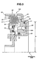
- Fig. 3 is a cross sectional view showing the forward clutch of the embodiment according to the present invention.
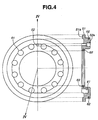
- Fig. 4 is a detailed view showing a hydraulic piston of the forward clutch in Fig. 3.
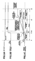
- Figs. 5A, 5B and 5C are time charts showing the control procedure at an engine restart period after an idle stop.
- Fig. 6 is a graph showing a relationship between a hydraulic pressure of the forward clutch and an engagement torque of the forward clutch.
- Fig. 7 is a cross sectional view showing a forward clutch compared with the forward clutch according to the present invention.
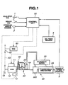
- the main unit of the vehicle comprises an internal combustion engine 10, an automatic transmission 20, a torque converter 30, a lockup clutch 40, a control unit 50, a starter motor 13, a 42-volt motor (motor/generator) 60 and the like as shown in Fig. 1.
- a fuel supply device 11 is attached to engine 10 so as to supply fuel to engine 10.
- a chain sprocket 12 is connected to engine 10 and is interconnected with a chain sprocket 62 connected to a motor/generator 60 via a chain 63.
- Motor/generator 60 functions as a generator of generating electric power according to a condition of starter motor 13, an operating condition of the generator under a vehicle decelerating condition and an electricity charged condition of a battery.
- starter motor 13 is used as a starter of starting engine 10 when engine 10 is first started, and motor/generator 60 is used as a starter when engine 10 is restarted after an idle stop was executed.
- a pump 22 of a mechanical type is provided in automatic transmission 20 and is driven by engine 10 to generate a hydraulic pressure.
- a control unit 50 is connected to an idle switch 1, a brake switch 2, a steering angle sensor 3, an oil temperature sensor 4 and a vehicle speed sensor 5 to receive signals thereof.
- Control unit 50 controls starter motor 13, motor/generator 60 and fuel supply device 11 according to the signal sent from the sensors 1, 2, 3, 4 and 5.
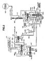
- Fig. 2 shows a hydraulic circuit diagram which represents a hydraulic supply to a forward clutch 190 of automatic transmission 20 of the embodiment according to the present invention.
- This hydraulic circuit comprises a pressure regulator valve 110, a clutch regulator valve 120, a pilot valve 130, a select switching solenoid 140 corresponding to a second engagement control actuator, a lockup solenoid valve 150 corresponding to a first engagement control actuator, a select switching valve 160, a select control valve 170, a manual valve 180, a forward clutch 190 corresponding to an engagement element, and a pressure modifier valve 200.
- the line pressure controlled by pressure regulator valve 110 is supplied to an oil passage 103 and an oil passage 105 via an oil passage 101 and an oil passage 102.
- the line pressure supplied to oil passage 102 is supplied to a shift control valve (not shown) and the like as a source pressure of a pulley hydraulic pressure.
- the line pressure supplied to oil passage 105 is supplied to a port 130a of pilot valve 130. Pilot valve 130 produces a pilot pressure by decreasing the line pressure to a constant pressure corresponding to a preset load of a spring in pilot valve 130.
- the line pressure supplied oil passage 103 is supplied to an oil passage 106 through an orifice 104.
- Clutch regulator valve 120 is disposed downstream of pressure regulator valve 110. Clutch regulator valve 120 controls the hydraulic pressure drained from pressure regulator valve 110. The hydraulic pressure controlled by clutch regulator valve 120 is used to control an engagement pressure of forward clutch 190.
- Pressure regulator valve 110 and clutch regulator valve 120 are controlled in pressure according to a signal pressure which is set according to a throttle opening and the like and which is supplied from pressure modifier valve 200. More specifically, the forward clutch hydraulic pressure set by clutch regulator valve 120 varies in synchronization with a pulley set pressure. For example, when a high pulley pressure is demanded, that is, when an input torque is large, the forward clutch hydraulic pressure is also increased to prevent a belt slippage on the pulley.
- a spool valve 160A of select switching valve 160 When select switching solenoid 140 is turned ON, a spool valve 160A of select switching valve 160 is pushed up along the upward direction in Fig. 2. In response to this lifting of spool valve 160A (under this ON state), the hydraulic pressure supplied from an oil passage 107 is supplied to forward clutch 190 via an oil passage 112, a port 170a, a port 170b of select control valve 170, a port 160b and a port 160a of select switching valve 160, an oil passage 115, a manual valve 180 and an oil passage 117 in the order of mention.
- select switching solenoid 140 When select switching solenoid 140 is turned OFF, spool valve 160A of select switching valve 160 is positioned at a lowermost position due to a biasing force of the spring installed in an upper portion in a cylinder of select switching valve 160. Under this OFF state, the hydraulic pressure supplied from oil passage 107 is supplied to forward clutch 190 via a port 160c of select switching valve 160, a port 160e of select switching valve 160, an oil passage 115, manual valve 180 and oil passage 170b in the order of mention.
- Fig. 4 shows a hydraulic piston 51 of forward clutch 190.
- a drawing located at the left hand side on Fig. 4 is a plan view of hydraulic piston 51 as viewed from an axial end of forward clutch 190.
- a drawing located at the right hand side on Fig. 4 is a cross sectional view of forward clutch 190.
- a plurality of springs 54 are disposed on hydraulic piston 51 at equal intervals. Therefore, a plurality of spring holes 61 are formed on hydraulic piston 51 at equal intervals so as to correspond with springs in position.
- a position of a ball receiving hole 51a of drift-on hole 52 is almost the same as the position of spring holes 61 in the diametrical direction, and is located between the adjacent two spring holes 61 in the circumferential direction. This arrangement enables hydraulic piston 51 to be formed small in diameter.
- hydraulic piston 52 forward clutch 190
- hydraulic piston 51 slides in the right hand side in Fig. 3, and drift-on ball 52 moves toward piston chamber 53.
- ball receiving hole 52a is opened and establishes a fluid communication between piston chamber 53 and a side of providing springs 54. Accordingly, the hydraulic fluid in piston chamber 53 is discharged through ball receiving hole52a.
- Fig. 6 shows a relationship between the hydraulic pressure and the engagement torque of forward clutch 190 of the embodiment according to the present invention.
- a horizontal axis denotes a hydraulic pressure
- a vertical axis denotes an engagement torque.
- Reference A on the horizontal axis is a hydraulic pressure corresponding to the maximum engagement pressure which is capable of being controlled by lockup solenoid 150
- reference B on the horizontal axis is the hydraulic pressure corresponding to the maximum engagement pressure which is capable of being controlled by clutch regulator valve 120.
- a conventional forward clutch has ensured a torque N 2 as a forward clutch engagement torque by receiving the hydraulic pressure A. This torque N 2 is sufficiently larger than a torque derived from the product of the maximum engine torque and the torque converter stall torque ratio.
- the effective cross sectional area of forward clutch 190 of the embodiment according to the present invention is set such that the forward clutch engagement torque obtained by the hydraulic pressure A corresponding to the maximum engagement pressure of lockup solenoid 150 becomes equal to the product N 1 of the maximum engine torque and the torque converter stall torque ratio.
- the effective cross sectional area of hydraulic piston chamber 53 is set at a necessary minimum cross sectional area which generates the engagement capacity capable of transmitting the torque corresponding to the product of the engine maximum torque and the torque converter stall torque ratio.
- This arrangement enables forward clutch 190 to be formed at a necessary minimum size.
- a hydraulic piston radius of forward clutch 190 of the embodiment according to the present invention shown in Fig. 3 is set at a
- a hydraulic piston radius of forward clutch of a related art shown in Fig. 7 is set at b.
- the conventional forward clutch shown in Fig. 7 is arranged such that the diametrical position of drift-on ball 52 is located outside of the diametrical position of springs 54 relative to a rotational axis. This arrangement possibly decreases a centrifugal hydraulic pressure caused by the residual hydraulic pressure after discharging the hydraulic pressure, at a small value.
- the conventional arrangement increases the hydraulic quantity to be supplied at a pre-charging phase of the engine restart period after the idle stop operation.
- forward clutch 190 of the embodiment according to the present invention is arranged such that the diametrical position of drift-on ball 52 generally corresponds to the diametrical positions of springs 54 so as to decrease the hydraulic piston radius a. Accordingly, it becomes possible to decrease the hydraulic supply quantity at the engine restarting period after the idle stop operation.
- an engine restart command pressure is outputted, and therefore the operation phase proceeds to the pre-charge phase.
- An engagement-pressure command pressure is set at a command pressure P0 which enables only the creep torque to be transmitted so as to output a constant command pressure without being affected by the throttle opening.
- the control of the engagement element is executed using the lockup solenoid 150 of controlling lockup clutch 40.
- the engagement phase starts, and the command pressure is set at the target engagement pressure determined according to throttle opening TVO and engine speed and is outputted.
- engagement timer value T0 becomes greater than or equal to a pre-set pressure control time, and select switching solenoid 140 is turned OFF. Accordingly, a not-controlled source pressure, that is, a controlled pressure controlled by clutch regulator valve 120 is directly supplied to forward clutch 190. At this moment, forward clutch 190 is put in the complete engagement state. Therefore, even if a high pressure is supplied to forward clutch 190, no engagement shock is caused thereby.
- the control is executed by controlling lockup solenoid 150. After the engagement is completed, the supply of the clutch pressure is executed by controlling select switching solenoid 140.
- the torque capacity of forward clutch 190 is controlled. Until forward clutch 190 is put in the lockup state, it is possible to execute the control using lockup solenoid 150. Therefore, it becomes possible to set the volume of piston chamber 53 of forward clutch 190 at a necessary minimum. This arrangement decreases the hydraulic fluid supply quantity, and enables the vehicle to quickly start running at the engine restart after the idle stop.
Landscapes
- Engineering & Computer Science (AREA)
- General Engineering & Computer Science (AREA)
- Mechanical Engineering (AREA)
- Physics & Mathematics (AREA)
- Fluid Mechanics (AREA)
- Hydraulic Clutches, Magnetic Clutches, Fluid Clutches, And Fluid Joints (AREA)
- Control Of Transmission Device (AREA)
Applications Claiming Priority (2)
| Application Number | Priority Date | Filing Date | Title |
|---|---|---|---|
| JP2004045610 | 2004-02-23 | ||
| JP2004045610A JP2005233357A (ja) | 2004-02-23 | 2004-02-23 | 自動変速機の油圧制御装置 |
Publications (1)
| Publication Number | Publication Date |
|---|---|
| EP1566577A2 true EP1566577A2 (fr) | 2005-08-24 |
Family
ID=34709170
Family Applications (1)
| Application Number | Title | Priority Date | Filing Date |
|---|---|---|---|
| EP05003768A Withdrawn EP1566577A2 (fr) | 2004-02-23 | 2005-02-22 | Système de contrôle pour pression hydraulique |
Country Status (3)
| Country | Link |
|---|---|
| US (1) | US7225907B2 (fr) |
| EP (1) | EP1566577A2 (fr) |
| JP (1) | JP2005233357A (fr) |
Cited By (1)
| Publication number | Priority date | Publication date | Assignee | Title |
|---|---|---|---|---|
| CN104019221A (zh) * | 2013-02-28 | 2014-09-03 | 福特全球技术公司 | 采用检测的输出扭矩的降档控制方法 |
Families Citing this family (6)
| Publication number | Priority date | Publication date | Assignee | Title |
|---|---|---|---|---|
| US7353725B2 (en) * | 2005-11-09 | 2008-04-08 | Caterpillar Inc. | Method of shifting gears in a work machine |
| JP4944660B2 (ja) * | 2007-04-13 | 2012-06-06 | 本田技研工業株式会社 | 車両用駆動力配分装置 |
| US8613681B2 (en) * | 2009-11-19 | 2013-12-24 | GM Global Technology Operations LLC | Transmission hydraulic control system having clutch compensator feed override |
| JP5331734B2 (ja) * | 2010-03-09 | 2013-10-30 | ジヤトコ株式会社 | 変速機構の制御装置およびその制御方法 |
| JP6119690B2 (ja) | 2014-07-14 | 2017-04-26 | マツダ株式会社 | 自動変速機の制御装置 |
| KR101734688B1 (ko) * | 2015-10-15 | 2017-05-11 | 현대자동차주식회사 | Ehps 시스템을 이용한 유압식 isg 시스템의 작동제어방법 및 장치 |
Citations (1)
| Publication number | Priority date | Publication date | Assignee | Title |
|---|---|---|---|---|
| JPH07269667A (ja) | 1994-03-31 | 1995-10-20 | Mazda Motor Corp | 自動変速機 |
Family Cites Families (4)
| Publication number | Priority date | Publication date | Assignee | Title |
|---|---|---|---|---|
| US2627189A (en) * | 1947-04-12 | 1953-02-03 | Packard Motor Car Co | Transmission |
| US2699074A (en) * | 1950-06-21 | 1955-01-11 | Gen Motors Corp | Transmission control system |
| US3747436A (en) * | 1971-06-28 | 1973-07-24 | Gen Electric | Power package |
| US5040648A (en) * | 1990-11-05 | 1991-08-20 | Caterpillar Inc. | Electrohydraulic control device for a drive train of a vehicle |
-
2004
- 2004-02-23 JP JP2004045610A patent/JP2005233357A/ja active Pending
-
2005
- 2005-02-22 EP EP05003768A patent/EP1566577A2/fr not_active Withdrawn
- 2005-02-23 US US11/062,487 patent/US7225907B2/en not_active Expired - Fee Related
Patent Citations (1)
| Publication number | Priority date | Publication date | Assignee | Title |
|---|---|---|---|---|
| JPH07269667A (ja) | 1994-03-31 | 1995-10-20 | Mazda Motor Corp | 自動変速機 |
Cited By (2)
| Publication number | Priority date | Publication date | Assignee | Title |
|---|---|---|---|---|
| CN104019221A (zh) * | 2013-02-28 | 2014-09-03 | 福特全球技术公司 | 采用检测的输出扭矩的降档控制方法 |
| CN104019221B (zh) * | 2013-02-28 | 2017-10-20 | 福特全球技术公司 | 采用检测的输出扭矩的降档控制方法 |
Also Published As
| Publication number | Publication date |
|---|---|
| US20050183916A1 (en) | 2005-08-25 |
| US7225907B2 (en) | 2007-06-05 |
| JP2005233357A (ja) | 2005-09-02 |
Similar Documents
| Publication | Publication Date | Title |
|---|---|---|
| US7815545B2 (en) | Hydraulic control system for automatic transmission | |
| EP2369202B1 (fr) | Dispositif de commande de pression d'huile pour transmission et son procédé de commande | |
| US8016718B2 (en) | Vehicle drive unit | |
| CN105984455B (zh) | 车辆的控制装置 | |
| KR20120117928A (ko) | 자동 변속기의 유압 제어 장치 | |
| US9365205B2 (en) | Hydraulic pressure control device for transmission | |
| US10247300B2 (en) | Method and device for controlling automatic transmission | |
| US7225907B2 (en) | Hydraulic pressure control system | |
| JP5396319B2 (ja) | 自動変速機の油圧供給装置 | |
| JP6551545B2 (ja) | 変速装置 | |
| EP2902666A1 (fr) | Transmission automatique et son procédé de commande | |
| US9540013B2 (en) | Hydraulic control system for vehicle | |
| US9567963B2 (en) | Vehicle control device | |
| JP5531735B2 (ja) | 車両制御システム | |
| EP1291540B1 (fr) | Système et procédure de commande d'un embrayage électromagnétique à disques multiples | |
| EP2908031A1 (fr) | Transmission automatique et son procédé de commande | |
| JP2004316480A (ja) | アイドルストップ車両用駆動装置 | |
| JP5397002B2 (ja) | 可変フライホイールの制御装置 | |
| JP3858972B2 (ja) | 車両の駆動装置 | |
| JP6261211B2 (ja) | 内燃機関の制御装置。 | |
| US20190368557A1 (en) | Disconnect clutch | |
| JP4573795B2 (ja) | 自動変速機の油圧制御装置 | |
| JP2015148256A (ja) | 油圧制御装置 | |
| EP2902673A1 (fr) | Transmission automatique et son procédé de commande | |
| JP6008692B2 (ja) | 制御装置 |
Legal Events
| Date | Code | Title | Description |
|---|---|---|---|
| PUAI | Public reference made under article 153(3) epc to a published international application that has entered the european phase |
Free format text: ORIGINAL CODE: 0009012 |
|
| 17P | Request for examination filed |
Effective date: 20050222 |
|
| AK | Designated contracting states |
Kind code of ref document: A2 Designated state(s): AT BE BG CH CY CZ DE DK EE ES FI FR GB GR HU IE IS IT LI LT LU MC NL PL PT RO SE SI SK TR |
|
| AX | Request for extension of the european patent |
Extension state: AL BA HR LV MK YU |
|
| STAA | Information on the status of an ep patent application or granted ep patent |
Free format text: STATUS: THE APPLICATION HAS BEEN WITHDRAWN |
|
| 18W | Application withdrawn |
Effective date: 20080108 |