EP1566576B1 - Procédé et dispositif pour immobiliser le stator d'un convertisseur de couple - Google Patents
Procédé et dispositif pour immobiliser le stator d'un convertisseur de couple Download PDFInfo
- Publication number
- EP1566576B1 EP1566576B1 EP05250891A EP05250891A EP1566576B1 EP 1566576 B1 EP1566576 B1 EP 1566576B1 EP 05250891 A EP05250891 A EP 05250891A EP 05250891 A EP05250891 A EP 05250891A EP 1566576 B1 EP1566576 B1 EP 1566576B1
- Authority
- EP
- European Patent Office
- Prior art keywords
- coupling sleeve
- reaction member
- coupling
- teeth
- stator support
- Prior art date
- Legal status (The legal status is an assumption and is not a legal conclusion. Google has not performed a legal analysis and makes no representation as to the accuracy of the status listed.)
- Expired - Lifetime
Links
Images





Classifications
-
- F—MECHANICAL ENGINEERING; LIGHTING; HEATING; WEAPONS; BLASTING
- F16—ENGINEERING ELEMENTS AND UNITS; GENERAL MEASURES FOR PRODUCING AND MAINTAINING EFFECTIVE FUNCTIONING OF MACHINES OR INSTALLATIONS; THERMAL INSULATION IN GENERAL
- F16D—COUPLINGS FOR TRANSMITTING ROTATION; CLUTCHES; BRAKES
- F16D41/00—Freewheels or freewheel clutches
- F16D41/12—Freewheels or freewheel clutches with hinged pawl co-operating with teeth, cogs, or the like
-
- F—MECHANICAL ENGINEERING; LIGHTING; HEATING; WEAPONS; BLASTING
- F16—ENGINEERING ELEMENTS AND UNITS; GENERAL MEASURES FOR PRODUCING AND MAINTAINING EFFECTIVE FUNCTIONING OF MACHINES OR INSTALLATIONS; THERMAL INSULATION IN GENERAL
- F16D—COUPLINGS FOR TRANSMITTING ROTATION; CLUTCHES; BRAKES
- F16D25/00—Fluid-actuated clutches
- F16D25/06—Fluid-actuated clutches in which the fluid actuates a piston incorporated in, i.e. rotating with the clutch
- F16D25/061—Fluid-actuated clutches in which the fluid actuates a piston incorporated in, i.e. rotating with the clutch the clutch having interengaging clutch members
-
- F—MECHANICAL ENGINEERING; LIGHTING; HEATING; WEAPONS; BLASTING
- F16—ENGINEERING ELEMENTS AND UNITS; GENERAL MEASURES FOR PRODUCING AND MAINTAINING EFFECTIVE FUNCTIONING OF MACHINES OR INSTALLATIONS; THERMAL INSULATION IN GENERAL
- F16H—GEARING
- F16H41/00—Rotary fluid gearing of the hydrokinetic type
- F16H41/24—Details
-
- F—MECHANICAL ENGINEERING; LIGHTING; HEATING; WEAPONS; BLASTING
- F16—ENGINEERING ELEMENTS AND UNITS; GENERAL MEASURES FOR PRODUCING AND MAINTAINING EFFECTIVE FUNCTIONING OF MACHINES OR INSTALLATIONS; THERMAL INSULATION IN GENERAL
- F16H—GEARING
- F16H41/00—Rotary fluid gearing of the hydrokinetic type
- F16H41/24—Details
- F16H2041/246—Details relating to one way clutch of the stator
Definitions
- the present invention relates to a method and apparatus for engaging a torque converter reaction member comprising a reaction member carrier coupling sleeve, a stator support coupling sleeve and a pawl mounted on the reaction member carrier coupling sleeve.
- Sprag-type clutches are well known by those skilled in the art. These clutches are often used since they have a freewheel mode desirable to some. These clutches, however, have numerous disadvantages including very tight and expensive to manufacture tolerances that required for them to operate properly. For example, the diameter and concentricity of the races is required to be exact for the clutches to work. In addition, sprag-type clutches often have insufficient capacity, and the sprag is prone to skidding or flipping over, resulting in a history of poor durability for these clutches. Negative experiences in the industry with these clutches have led manufactures to cease offering freewheel clutches in the marketplace, with limited exceptions.
- US 2389 520 A discloses the features of the preamble of claim 1 or 11.
- U.S. Patent Nos. 5,718,114 and 5,852,932 teach a mechanism comprising an outer race on an inner circumferential side of a stator.
- the outer race includes a first side face being formed with first teeth.
- the mechanism also comprises an unrotatable inner race assembled on a stationary shaft.
- the inner race includes a second side face, opposite the first side face, formed with second teeth which can prohibit the outer race from rotating in one direction by meshing with the first teeth.
- the inner and outer races move axially with fluid pressure so that the first teeth and second teeth can be engaged and disengaged.
- a structure to adequately align and initiate engagement of the first and the second teeth is absent from these inventions. As a consequence, excessive wear on the teeth, noise and/or vibration may result.
- the present invention is directed toward a mechanism for a torque converter comprising a pawl, a reaction member carrier coupling sleeve, and a stator support coupling sleeve supported for axial movement along a helical spine.
- the reaction member carrier coupling sleeve comprises a first set of carrier coupling teeth and the stator support coupling sleeve comprises a second set of carrier coupling teeth for selectively engaging the first set of coupling teeth.
- the stator support coupling sleeve also comprises a plurality of indexing slots.
- the pawl is pivotally mounted on the reaction member carrier coupling sleeve.
- the present invention is also directed toward a method for selectively engaging a torque converter reaction member comprising providing the reaction member carrier coupling sleeve, locating the stator support coupling sleeve on a helical spline for axial movement, and selectively engaging the pawl into one of the plurality of indexing slots to engage the first set of coupling teeth and the second set of coupling teeth.
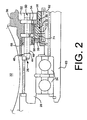
- a mechanism 26 for the torque converter assembly 24 is provided comprising a reaction member carrier coupling sleeve 28 and a stator support coupling sleeve 30.
- the reaction member carrier coupling sleeve 28 is connected to a torque converter reaction member 32, as known to those skilled in the art.
- At least two bearings 34 adjacent the reaction member carrier coupling sleeve 28 facilitate its rotation.
- a quantity of hydraulic fluid 36 is located among the reaction member carrier coupling sleeve 28 and the stator support coupling sleeve 30, as known to those skilled in the art.
- the reaction member carrier coupling sleeve 28 is comprised of first set of coupling teeth 38.
- the first set of coupling teeth 38 may have any design known to those skilled in the art. In a preferred embodiment, however, the individual teeth of the first set of coupling teeth 38 have a curvilinear, or curvic, design.
- a pawl pivot pin 44 is mounted in a predetermined location, described in more detail below, on the reaction member carrier coupling sleeve 28.
- a first end 46 of the pawl pivot pin 44 is located in a hole 48 in the reaction member carrier coupling sleeve 28.
- a second end 50 of the pawl pivot pin 44 is located in a retainer plate 52.
- the retainer plate 52 is held in place by one or more mechanical fasteners (not shown), such as bolts, attached to the reaction member carrier coupling sleeve 28.
- a pawl 54 is pivotally mounted on the pawl pivot pin 44.
- a spacer 56 may be located on the pawl pivot pin 44 between the pawl 54 and the reaction member carrier coupling sleeve 28 to locate the pawl 54 in a position to engage the stator support coupling sleeve 30, described in more detail below.
- one or more coil springs 58 are placed in contact with the pawl 54 to bias it toward the stator support coupling sleeve 30.
- a coil spring 58 is depicted in Fig. 2 , those skilled in the art will appreciate that other means to bias the pawl 54 may be used without departing from the scope of the present invention.
- a stop 60 is preferably located on the reaction member carrier coupling sleeve 28 to prevent the pawl 54 from rotating beyond a predetermined distance from the stator support coupling sleeve 30.
- the stop 60 is depicted as a pin extending from the reaction member carrier coupling sleeve 28, however, any structure to prevent movement of the pawl 54 beyond a predetermined distance from the stator support coupling sleeve 30 may be used.
- an inner splined sleeve 62 is provided on which the stator support coupling sleeve 30 is located.
- the inner splined sleeve 62 comprises a plurality of helical splines 64 on its outside surface 66.
- An internal surface 68 of the stator support coupling sleeve 30 has a plurality of helical splines 65 complementary design to the plurality of helical splines 64.
- the inner splined sleeve 62 is located on a stator support 63.
- the plurality of helical splines 65 mesh with the plurality of helical splines 64 to allow the stator support coupling sleeve 30 to move in the axial direction while rotating at the same time.
- the stator support coupling sleeve 30 moves between a first axial position 70 to a second axial position 72 along the helical splines 64, 65, as best seen in Fig. 2 .
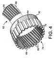
- the stator support coupling sleeve 30 preferably comprises a second set of coupling teeth 74 having a complementary design to the first set of coupling teeth 38.
- individual teeth of the second set of coupling teeth 74 have a curvilinear, or curvic, design.
- the first set of coupling teeth 38 and the second set of coupling teeth 74 selectively define a gap 80 between them. As described in more detail below, the first and second sets of coupling teeth 38, 74 vary the width of the gap 80 during various modes of operation of the mechanism 26, including one mode where the gap 80 is eliminated.
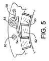
- the stator support coupling sleeve 30 comprises a plurality of indexing slots 82.
- Each slot 82 is defined by at least two upstanding portions 84. Additional material may be added to the at least two upstanding portions 84 to extend them in the radial direction.
- a preferred method of selectively engaging the torque converter reaction member 32 comprises rotating the reaction member carrier coupling sleeve 28, which carries the first set of coupling teeth 38.
- hydraulic loads on the reaction member 32 cause it to rotate in the clockwise or counterclockwise direction. Rotation in the clockwise direction is referred to as the freewheel state and rotation in the counterclockwise direction is referred to as the loaded state.
- the reaction member carrier coupling sleeve 28 rotates with the reaction member 32.
- the rotation of the first set of coupling teeth 38 in the counterclockwise direction during the loaded state produces a first hydraulic fluid force that acts on the stator support coupling sleeve 30 and urges it away from the reaction member carrier coupling sleeve 28.
- the first hydraulic fluid force moves the stator support coupling sleeve 30 in a first axial direction 88 to disengage the first set of coupling teeth 38 and the second set of coupling teeth 74, as depicted in Fig. 2 .
- the first hydraulic fluid force is sufficient to maintain the first set of coupling teeth 38 and the second set of coupling teeth 74 in the disengaged position. In the disengaged position, the gap 80 between the sets of coupling teeth 38, 74 is present.
- stator support coupling sleeve 30 moves in the first axial direction 88 while its helical spine 65 is rotationally engaged with the helical spine 64 of the inner splined sleeve 62.
- the upstanding portion prevents the pawl 54 from additional motion across the stator support coupling sleeve 30.
- the reaction member 32 continues to rotate.
- the pawl 54 engaged with the stator support coupling sleeve 30, drives the stator support coupling sleeve so that it rotates with the reaction member 30.
- the plurality of helical splines 65 of the stator support coupling sleeve 30 are engaged with the plurality of helical splines 64 of the inner splined sleeve 62 to cause the stator support coupling sleeve 30 to move in the second axial direction 92 while the sleeve 30 rotates, as shown in Fig. 2 .
- the second set of coupling teeth 74 on the stator support coupling sleeve 30 are brought closer to the second set of coupling teeth 74 and the gap 80 is gradually closed.
- the reaction member 32 and pawl 54 rotate the stator support coupling sleeve 30 to a pre-determined position in which the second set of coupling teeth 74 are in a complementary orientation with the first set of coupling teeth 38. More specifically, the second set of coupling teeth 74 are aligned between the first set of coupling teeth 38, as depicted in Fig. 6 .
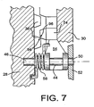
- the first set of coupling teeth 38 and the second set of coupling teeth 74 make initial contact, as shown in Fig. 7 .
- the initial contact is made between a first portion 94 of the first set of coupling teeth 38 and a first portion 96 of the second set of coupling teeth 74.
- the pressure angle on the first and second sets of coupling teeth 38, 74 displaces the radial alignment between the reaction member coupling sleeve 28 and the stator support coupling sleeve 30, as depicted in Fig. 8 .
- Displacing the radial alignment between the sleeves 28, 30, urges the pawl 54 out of engagement with the indexing slots 82 on the stator support coupling sleeve 30, as seen in Fig. 9 .
- the stator support coupling sleeve 30 continues to move in the second axial direction 92 causing the first and second set of coupling teeth 38, 74 to fully engage with each other.
- the fully engaged sets of teeth 38, 74 lock the reaction member carrier coupling sleeve 28 to the stator support coupling sleeve 30 so that all the torque from the reaction member carrier coupling sleeve 28 is carried by the first and second sets of coupling teeth 38, 74.
- the pawl 54 disengages from the indexing slots 82 so that it no longer carries the torque load of the reaction member carrier coupling sleeve 28, as shown in Fig. 3 .
- the above-described invention thus enables the torque converter assembly 24 to operate between the loaded and the freewheel state and vice versa.
Landscapes
- Engineering & Computer Science (AREA)
- General Engineering & Computer Science (AREA)
- Mechanical Engineering (AREA)
- Mechanical Operated Clutches (AREA)
- Brushless Motors (AREA)
- Control Of Motors That Do Not Use Commutators (AREA)
- Automatic Assembly (AREA)
Claims (18)
- Mécanisme pour un convertisseur de couple, comprenant:un manchon de couplage porteur de l'élément de réaction (28) comprenant un premier ensemble de dents de couplage (38);un manchon de couplage de support de stator (30) supporté en vue d'un mouvement axial et comprenant un deuxième ensemble de dents de couplage (74); caractérisé parun cliquet (54) installé d'une manière pivotante sur ledit manchon de couplage porteur de l'élément de réaction (28) pour une mise en prise sélective dudit deuxième ensemble de dents de couplage (74) avec ledit premier ensemble de dents de couplage (38).
- Mécanisme selon la revendication 1, où ledit manchon de couplage porteur de l'élément de réaction (28) est relié à un élément de réaction de convertisseur de couple (32).
- Mécanisme selon la revendication 1, dans lequel au moins un ressort (58) est en contact avec ledit cliquet (54) pour solliciter ledit cliquet (54) dans ledit manchon de couplage de support de stator (28).
- Mécanisme selon la revendication 1, dans lequel ledit premier ensemble de dents de couplage (38) et ledit deuxième ensemble de dents de couplage (74) sont curvilignes.
- Mécanisme selon la revendication 1, dans lequel ledit premier ensemble de dents de couplage (38) et ledit deuxième ensemble de dents de couplage (74) définissent sélectivement un espace (80) entre eux.
- Mécanisme selon la revendication 1, dans lequel ledit manchon de couplage de support de stator (28) possède une pluralité de cannelures hélicoïdales (65) sur une surface intérieure (68) en vue d'un mouvement axial de rotation entre une première position axiale (70) et une deuxième position axiale (72).
- Mécanisme selon la revendication 1, dans lequel ladite pluralité de cannelures hélicoïdales (65) dudit manchon de couplage de support de stator (28) engrènent avec une pluralité de cannelures hélicoïdales complémentaires (64) sur un manchon cannelé intérieur (62).
- Mécanisme selon la revendication 1, dans lequel ledit cliquet (54) est monté d'une manière pivotante sur ledit manchon de couplage porteur de l'élément de réaction (28) par au moins un axe (44).
- Mécanisme selon la revendication 1, dans lequel ledit cliquet (54) vient sélectivement en prise avec une d'une pluralité de fentes d'indexation (82) sur ledit manchon de couplage de support de stator (28).
- Mécanisme selon la revendication 1, dans lequel au moins une butée d'arrêt (60) sur ledit manchon de couplage porteur de l'élément de réaction (28) empêche un mouvement dudit cliquet (54) au-delà d'une distance prédéterminée de ladite pluralité de fentes d'indexation (82).
- Procédé pour une mise en prise sélective d'un élément de réaction de convertisseur de couple, comprenant:réaliser un manchon de couplage porteur de l'élément de réaction (28) comprenant un premier ensemble de dents de couplage (38);localiser un manchon de couplage de support de stator (30) sur une pluralité de cannelures hélicoïdales (65) pour déplacer sélectivement ledit manchon de couplage de support de stator (30) dans une direction axiale, ledit manchon de couplage de support de stator (30) comprenant un deuxième ensemble de dents de couplage (74); caractérisé parmettre en prise sélectivement un cliquet (54) avec une d'une pluralité de fentes d'indexation (82) sur ledit manchon de couplage de support de stator (30) pour mettre en prise sélectivement ledit premier ensemble de dents de couplage (38) et ledit deuxième ensemble de dents de couplage (74).
- Procédé selon la revendication 11, dans lequel une première force de fluide hydraulique produite par ledit manchon de couplage de l'élément de réaction (28) fait tourner ledit manchon de couplage de support de stator (30) dans une première direction axiale (88) au loin dudit manchon de couplage porteur de l'élément de réaction (28).
- Procédé selon la revendication 11, dans lequel ledit cliquet (54) est positionné sur ledit manchon de couplage porteur de l'élément de réaction (28) pour la mise en prise de ladite pluralité de fentes d'indexation (82) sur ledit manchon de couplage de support de stator (30) pour aligner ledit deuxième ensemble de dents de couplage (74) avec ledit premier ensemble de dents de couplage (38).
- Procédé selon la revendication 11, dans lequel ledit cliquet (54) est positionné sur ledit manchon de couplage porteur de l'élément de réaction (28) pour la mise en prise avec une de ladite pluralité de fentes d'indexation (82) sur ledit manchon de couplage de support de stator (30) lorsque ledit manchon de couplage de support de stator (30) est localisé dans une première position axiale (70).
- Procédé selon la revendication 11, dans lequel une première portion (94) dudit premier ensemble de dents de couplage (38) vient en contact avec une première portion (96) dudit deuxième ensemble de dents de couplage (74) créant un décalage entre ledit premier ensemble de dents de couplage (38) et ledit deuxième ensemble de dents de couplage (74).
- Procédé selon la revendication 15, dans lequel ledit décalage sollicite ledit cliquet (54) hors prise avec ladite pluralité de fentes d'indexation (82).
- Procédé selon la revendication 11, dans lequel ledit premier ensemble de dents de couplage (38) et ledit deuxième ensemble de dents de couplage (74) engrènent complètement pour verrouiller ledit manchon de couplage porteur de l'élément de réaction (28) et ledit manchon de couplage de support de stator (30) ensemble.
- Procédé selon la revendication 11, dans lequel ledit cliquet (54) vient en prise avec une de ladite pluralité de fentes d'indexation (82) pour faire tourner ledit manchon de couplage de support de stator (30) le long d'une pluralité de cannelures (65) dans une deuxième direction axiale (92) vers ledit manchon de couplage porteur de l'élément de réaction (28).
Applications Claiming Priority (2)
| Application Number | Priority Date | Filing Date | Title |
|---|---|---|---|
| US781394 | 2004-02-18 | ||
| US10/781,394 US6945038B2 (en) | 2004-02-18 | 2004-02-18 | Method and apparatus for engaging a torque converter reaction member |
Publications (3)
| Publication Number | Publication Date |
|---|---|
| EP1566576A2 EP1566576A2 (fr) | 2005-08-24 |
| EP1566576A3 EP1566576A3 (fr) | 2009-07-15 |
| EP1566576B1 true EP1566576B1 (fr) | 2011-01-05 |
Family
ID=34711850
Family Applications (1)
| Application Number | Title | Priority Date | Filing Date |
|---|---|---|---|
| EP05250891A Expired - Lifetime EP1566576B1 (fr) | 2004-02-18 | 2005-02-16 | Procédé et dispositif pour immobiliser le stator d'un convertisseur de couple |
Country Status (4)
| Country | Link |
|---|---|
| US (1) | US6945038B2 (fr) |
| EP (1) | EP1566576B1 (fr) |
| AT (1) | ATE494496T1 (fr) |
| DE (1) | DE602005025707D1 (fr) |
Family Cites Families (6)
| Publication number | Priority date | Publication date | Assignee | Title |
|---|---|---|---|---|
| US2389520A (en) * | 1941-07-17 | 1945-11-20 | Clark Equipment Co | Torque converter |
| US2461217A (en) * | 1945-05-31 | 1949-02-08 | Clark Equipment Co | One-way brake for torque converters |
| US2551000A (en) * | 1946-05-31 | 1951-05-01 | Studebaker Corp | Overrunning clutch |
| WO1982004109A1 (fr) * | 1981-05-19 | 1982-11-25 | Hedlund Sven Benny | Convertisseurs de couple |
| JP3293463B2 (ja) * | 1995-07-10 | 2002-06-17 | トヨタ自動車株式会社 | トルクコンバータのワンウェイクラッチ機構 |
| JPH09303529A (ja) | 1996-05-17 | 1997-11-25 | Toyota Motor Corp | トルクコンバータのワンウェイクラッチ機構 |
-
2004
- 2004-02-18 US US10/781,394 patent/US6945038B2/en not_active Expired - Fee Related
-
2005
- 2005-02-16 AT AT05250891T patent/ATE494496T1/de not_active IP Right Cessation
- 2005-02-16 EP EP05250891A patent/EP1566576B1/fr not_active Expired - Lifetime
- 2005-02-16 DE DE602005025707T patent/DE602005025707D1/de not_active Expired - Lifetime
Also Published As
| Publication number | Publication date |
|---|---|
| US20050178112A1 (en) | 2005-08-18 |
| DE602005025707D1 (de) | 2011-02-17 |
| US6945038B2 (en) | 2005-09-20 |
| ATE494496T1 (de) | 2011-01-15 |
| EP1566576A2 (fr) | 2005-08-24 |
| EP1566576A3 (fr) | 2009-07-15 |
Similar Documents
| Publication | Publication Date | Title |
|---|---|---|
| JP4993924B2 (ja) | 変速機の遊星歯車装置用キャリア組立体 | |
| EP1944520B1 (fr) | Embrayage à roue libre sélectionnable avec jambes de force symétriques | |
| JP6397051B2 (ja) | 径方向配向デカップリング機構を有するプーリーアセンブリ | |
| US8042670B2 (en) | Selectable one-way clutch with radial integrated forward/reverse rockers | |
| US5690202A (en) | Overrunning clutch mechanism | |
| JP3916307B2 (ja) | 多板摩擦クラッチを有するロッキング差動装置 | |
| US7455156B2 (en) | Overrunning clutch | |
| JP4961149B2 (ja) | ワンウェイ・クラッチ | |
| US8286772B2 (en) | Controllable coupling assembly and overrunning coupling and control assembly utilizing same | |
| US11047434B2 (en) | One-way clutch operable with one or no races and without race pockets for locking elements | |
| CN102105715B (zh) | 用于可选择单向离合器的紧凑型选择机构 | |
| CN104285071B (zh) | 销和棘爪式双向超越离合器 | |
| CN101960162B (zh) | 滚子式单向离合器 | |
| US10247263B2 (en) | Selectable one-way clutch | |
| US7878316B2 (en) | High torque one way clutch | |
| JPS6263246A (ja) | クラツチ装置付きシフト機構 | |
| CN107438724A (zh) | 用于多模式离合器模块的力平衡曲拐致动器 | |
| JPH11108085A (ja) | オーバーランニングクラッチ | |
| US8776971B2 (en) | Stator and one-way clutch assembly for a torque converter | |
| EP1566576B1 (fr) | Procédé et dispositif pour immobiliser le stator d'un convertisseur de couple | |
| CN101398042B (zh) | 组合式超越离合器 | |
| WO2006121743A1 (fr) | Entrainement a cliquet pour transfert de couple entre deux elements rotatifs | |
| JP4818150B2 (ja) | クラッチ装置 | |
| JP3791121B2 (ja) | 動力伝達装置 | |
| JP2019173921A (ja) | ワンウェイクラッチ |
Legal Events
| Date | Code | Title | Description |
|---|---|---|---|
| PUAI | Public reference made under article 153(3) epc to a published international application that has entered the european phase |
Free format text: ORIGINAL CODE: 0009012 |
|
| AK | Designated contracting states |
Kind code of ref document: A2 Designated state(s): AT BE BG CH CY CZ DE DK EE ES FI FR GB GR HU IE IS IT LI LT LU MC NL PL PT RO SE SI SK TR |
|
| AX | Request for extension of the european patent |
Extension state: AL BA HR LV MK YU |
|
| RAP1 | Party data changed (applicant data changed or rights of an application transferred) |
Owner name: DANA HEAVY VEHICLE SYSTEMS GROUP, LLC |
|
| PUAL | Search report despatched |
Free format text: ORIGINAL CODE: 0009013 |
|
| AK | Designated contracting states |
Kind code of ref document: A3 Designated state(s): AT BE BG CH CY CZ DE DK EE ES FI FR GB GR HU IE IS IT LI LT LU MC NL PL PT RO SE SI SK TR |
|
| AX | Request for extension of the european patent |
Extension state: AL BA HR LV MK YU |
|
| RIC1 | Information provided on ipc code assigned before grant |
Ipc: F16H 41/24 20060101AFI20050525BHEP Ipc: F16D 23/10 20060101ALI20090610BHEP Ipc: F16D 41/22 20060101ALI20090610BHEP |
|
| 17P | Request for examination filed |
Effective date: 20100111 |
|
| AKX | Designation fees paid |
Designated state(s): AT BE BG CH CY CZ DE DK EE ES FI FR GB GR HU IE IS IT LI LT LU MC NL PL PT RO SE SI SK TR |
|
| GRAP | Despatch of communication of intention to grant a patent |
Free format text: ORIGINAL CODE: EPIDOSNIGR1 |
|
| GRAS | Grant fee paid |
Free format text: ORIGINAL CODE: EPIDOSNIGR3 |
|
| GRAA | (expected) grant |
Free format text: ORIGINAL CODE: 0009210 |
|
| AK | Designated contracting states |
Kind code of ref document: B1 Designated state(s): AT BE BG CH CY CZ DE DK EE ES FI FR GB GR HU IE IS IT LI LT LU MC NL PL PT RO SE SI SK TR |
|
| REG | Reference to a national code |
Ref country code: GB Ref legal event code: FG4D |
|
| REG | Reference to a national code |
Ref country code: CH Ref legal event code: EP |
|
| REG | Reference to a national code |
Ref country code: IE Ref legal event code: FG4D |
|
| REF | Corresponds to: |
Ref document number: 602005025707 Country of ref document: DE Date of ref document: 20110217 Kind code of ref document: P |
|
| REG | Reference to a national code |
Ref country code: DE Ref legal event code: R096 Ref document number: 602005025707 Country of ref document: DE Effective date: 20110217 |
|
| REG | Reference to a national code |
Ref country code: NL Ref legal event code: VDEP Effective date: 20110105 |
|
| PG25 | Lapsed in a contracting state [announced via postgrant information from national office to epo] |
Ref country code: SI Free format text: LAPSE BECAUSE OF FAILURE TO SUBMIT A TRANSLATION OF THE DESCRIPTION OR TO PAY THE FEE WITHIN THE PRESCRIBED TIME-LIMIT Effective date: 20110105 |
|
| LTIE | Lt: invalidation of european patent or patent extension |
Effective date: 20110105 |
|
| PG25 | Lapsed in a contracting state [announced via postgrant information from national office to epo] |
Ref country code: SE Free format text: LAPSE BECAUSE OF FAILURE TO SUBMIT A TRANSLATION OF THE DESCRIPTION OR TO PAY THE FEE WITHIN THE PRESCRIBED TIME-LIMIT Effective date: 20110105 Ref country code: IS Free format text: LAPSE BECAUSE OF FAILURE TO SUBMIT A TRANSLATION OF THE DESCRIPTION OR TO PAY THE FEE WITHIN THE PRESCRIBED TIME-LIMIT Effective date: 20110505 Ref country code: ES Free format text: LAPSE BECAUSE OF FAILURE TO SUBMIT A TRANSLATION OF THE DESCRIPTION OR TO PAY THE FEE WITHIN THE PRESCRIBED TIME-LIMIT Effective date: 20110416 Ref country code: GR Free format text: LAPSE BECAUSE OF FAILURE TO SUBMIT A TRANSLATION OF THE DESCRIPTION OR TO PAY THE FEE WITHIN THE PRESCRIBED TIME-LIMIT Effective date: 20110406 Ref country code: LT Free format text: LAPSE BECAUSE OF FAILURE TO SUBMIT A TRANSLATION OF THE DESCRIPTION OR TO PAY THE FEE WITHIN THE PRESCRIBED TIME-LIMIT Effective date: 20110105 Ref country code: PT Free format text: LAPSE BECAUSE OF FAILURE TO SUBMIT A TRANSLATION OF THE DESCRIPTION OR TO PAY THE FEE WITHIN THE PRESCRIBED TIME-LIMIT Effective date: 20110505 |
|
| PG25 | Lapsed in a contracting state [announced via postgrant information from national office to epo] |
Ref country code: FI Free format text: LAPSE BECAUSE OF FAILURE TO SUBMIT A TRANSLATION OF THE DESCRIPTION OR TO PAY THE FEE WITHIN THE PRESCRIBED TIME-LIMIT Effective date: 20110105 Ref country code: CY Free format text: LAPSE BECAUSE OF FAILURE TO SUBMIT A TRANSLATION OF THE DESCRIPTION OR TO PAY THE FEE WITHIN THE PRESCRIBED TIME-LIMIT Effective date: 20110105 Ref country code: BG Free format text: LAPSE BECAUSE OF FAILURE TO SUBMIT A TRANSLATION OF THE DESCRIPTION OR TO PAY THE FEE WITHIN THE PRESCRIBED TIME-LIMIT Effective date: 20110405 Ref country code: AT Free format text: LAPSE BECAUSE OF FAILURE TO SUBMIT A TRANSLATION OF THE DESCRIPTION OR TO PAY THE FEE WITHIN THE PRESCRIBED TIME-LIMIT Effective date: 20110105 Ref country code: NL Free format text: LAPSE BECAUSE OF FAILURE TO SUBMIT A TRANSLATION OF THE DESCRIPTION OR TO PAY THE FEE WITHIN THE PRESCRIBED TIME-LIMIT Effective date: 20110105 Ref country code: BE Free format text: LAPSE BECAUSE OF FAILURE TO SUBMIT A TRANSLATION OF THE DESCRIPTION OR TO PAY THE FEE WITHIN THE PRESCRIBED TIME-LIMIT Effective date: 20110105 Ref country code: PL Free format text: LAPSE BECAUSE OF FAILURE TO SUBMIT A TRANSLATION OF THE DESCRIPTION OR TO PAY THE FEE WITHIN THE PRESCRIBED TIME-LIMIT Effective date: 20110105 |
|
| PG25 | Lapsed in a contracting state [announced via postgrant information from national office to epo] |
Ref country code: MC Free format text: LAPSE BECAUSE OF NON-PAYMENT OF DUE FEES Effective date: 20110228 |
|
| REG | Reference to a national code |
Ref country code: CH Ref legal event code: PL |
|
| PG25 | Lapsed in a contracting state [announced via postgrant information from national office to epo] |
Ref country code: LI Free format text: LAPSE BECAUSE OF NON-PAYMENT OF DUE FEES Effective date: 20110228 Ref country code: CH Free format text: LAPSE BECAUSE OF NON-PAYMENT OF DUE FEES Effective date: 20110228 Ref country code: EE Free format text: LAPSE BECAUSE OF FAILURE TO SUBMIT A TRANSLATION OF THE DESCRIPTION OR TO PAY THE FEE WITHIN THE PRESCRIBED TIME-LIMIT Effective date: 20110105 Ref country code: DK Free format text: LAPSE BECAUSE OF FAILURE TO SUBMIT A TRANSLATION OF THE DESCRIPTION OR TO PAY THE FEE WITHIN THE PRESCRIBED TIME-LIMIT Effective date: 20110105 |
|
| PLBE | No opposition filed within time limit |
Free format text: ORIGINAL CODE: 0009261 |
|
| STAA | Information on the status of an ep patent application or granted ep patent |
Free format text: STATUS: NO OPPOSITION FILED WITHIN TIME LIMIT |
|
| REG | Reference to a national code |
Ref country code: FR Ref legal event code: ST Effective date: 20111102 |
|
| REG | Reference to a national code |
Ref country code: IE Ref legal event code: MM4A |
|
| PG25 | Lapsed in a contracting state [announced via postgrant information from national office to epo] |
Ref country code: SK Free format text: LAPSE BECAUSE OF FAILURE TO SUBMIT A TRANSLATION OF THE DESCRIPTION OR TO PAY THE FEE WITHIN THE PRESCRIBED TIME-LIMIT Effective date: 20110105 Ref country code: RO Free format text: LAPSE BECAUSE OF FAILURE TO SUBMIT A TRANSLATION OF THE DESCRIPTION OR TO PAY THE FEE WITHIN THE PRESCRIBED TIME-LIMIT Effective date: 20110105 Ref country code: CZ Free format text: LAPSE BECAUSE OF FAILURE TO SUBMIT A TRANSLATION OF THE DESCRIPTION OR TO PAY THE FEE WITHIN THE PRESCRIBED TIME-LIMIT Effective date: 20110105 |
|
| 26N | No opposition filed |
Effective date: 20111006 |
|
| GBPC | Gb: european patent ceased through non-payment of renewal fee |
Effective date: 20110405 |
|
| PG25 | Lapsed in a contracting state [announced via postgrant information from national office to epo] |
Ref country code: IT Free format text: LAPSE BECAUSE OF FAILURE TO SUBMIT A TRANSLATION OF THE DESCRIPTION OR TO PAY THE FEE WITHIN THE PRESCRIBED TIME-LIMIT Effective date: 20110105 |
|
| REG | Reference to a national code |
Ref country code: DE Ref legal event code: R119 Ref document number: 602005025707 Country of ref document: DE Effective date: 20110901 |
|
| PG25 | Lapsed in a contracting state [announced via postgrant information from national office to epo] |
Ref country code: FR Free format text: LAPSE BECAUSE OF NON-PAYMENT OF DUE FEES Effective date: 20110307 Ref country code: IE Free format text: LAPSE BECAUSE OF NON-PAYMENT OF DUE FEES Effective date: 20110216 |
|
| PG25 | Lapsed in a contracting state [announced via postgrant information from national office to epo] |
Ref country code: GB Free format text: LAPSE BECAUSE OF NON-PAYMENT OF DUE FEES Effective date: 20110405 |
|
| PG25 | Lapsed in a contracting state [announced via postgrant information from national office to epo] |
Ref country code: LU Free format text: LAPSE BECAUSE OF NON-PAYMENT OF DUE FEES Effective date: 20110216 |
|
| PG25 | Lapsed in a contracting state [announced via postgrant information from national office to epo] |
Ref country code: DE Free format text: LAPSE BECAUSE OF NON-PAYMENT OF DUE FEES Effective date: 20110901 |
|
| PG25 | Lapsed in a contracting state [announced via postgrant information from national office to epo] |
Ref country code: TR Free format text: LAPSE BECAUSE OF FAILURE TO SUBMIT A TRANSLATION OF THE DESCRIPTION OR TO PAY THE FEE WITHIN THE PRESCRIBED TIME-LIMIT Effective date: 20110105 |
|
| PG25 | Lapsed in a contracting state [announced via postgrant information from national office to epo] |
Ref country code: HU Free format text: LAPSE BECAUSE OF FAILURE TO SUBMIT A TRANSLATION OF THE DESCRIPTION OR TO PAY THE FEE WITHIN THE PRESCRIBED TIME-LIMIT Effective date: 20110105 |