EP1565303B1 - Procede de fabrication de tubes souples plastiques ou metalloplastiques - Google Patents
Procede de fabrication de tubes souples plastiques ou metalloplastiques Download PDFInfo
- Publication number
- EP1565303B1 EP1565303B1 EP03778414A EP03778414A EP1565303B1 EP 1565303 B1 EP1565303 B1 EP 1565303B1 EP 03778414 A EP03778414 A EP 03778414A EP 03778414 A EP03778414 A EP 03778414A EP 1565303 B1 EP1565303 B1 EP 1565303B1
- Authority
- EP
- European Patent Office
- Prior art keywords
- web
- strip
- tools
- cylindrical sleeve
- rolls
- Prior art date
- Legal status (The legal status is an assumption and is not a legal conclusion. Google has not performed a legal analysis and makes no representation as to the accuracy of the status listed.)
- Expired - Lifetime
Links
- 238000000034 method Methods 0.000 title claims abstract description 17
- 230000009975 flexible effect Effects 0.000 title claims abstract description 14
- 229920003023 plastic Polymers 0.000 title claims abstract description 10
- 239000004033 plastic Substances 0.000 title claims abstract description 10
- 239000002184 metal Substances 0.000 claims description 7
- 229910052751 metal Inorganic materials 0.000 claims description 7
- 238000007493 shaping process Methods 0.000 claims description 7
- 238000005034 decoration Methods 0.000 claims description 5
- 238000004049 embossing Methods 0.000 description 21
- 239000004698 Polyethylene Substances 0.000 description 16
- 238000004519 manufacturing process Methods 0.000 description 15
- 238000005096 rolling process Methods 0.000 description 12
- 229920006226 ethylene-acrylic acid Polymers 0.000 description 10
- 238000011144 upstream manufacturing Methods 0.000 description 9
- 239000012815 thermoplastic material Substances 0.000 description 8
- 238000003466 welding Methods 0.000 description 8
- 230000000694 effects Effects 0.000 description 6
- KWGRBVOPPLSCSI-WPRPVWTQSA-N (-)-ephedrine Chemical compound CN[C@@H](C)[C@H](O)C1=CC=CC=C1 KWGRBVOPPLSCSI-WPRPVWTQSA-N 0.000 description 4
- 238000003490 calendering Methods 0.000 description 4
- 230000006872 improvement Effects 0.000 description 4
- 239000000463 material Substances 0.000 description 4
- 239000000047 product Substances 0.000 description 4
- 238000011282 treatment Methods 0.000 description 4
- XLYOFNOQVPJJNP-UHFFFAOYSA-N water Substances O XLYOFNOQVPJJNP-UHFFFAOYSA-N 0.000 description 4
- 229910001868 water Inorganic materials 0.000 description 4
- 238000005452 bending Methods 0.000 description 3
- 229920001971 elastomer Polymers 0.000 description 3
- 238000011049 filling Methods 0.000 description 3
- 238000010438 heat treatment Methods 0.000 description 3
- 229920001903 high density polyethylene Polymers 0.000 description 3
- 239000004700 high-density polyethylene Substances 0.000 description 3
- 230000002427 irreversible effect Effects 0.000 description 3
- -1 polyéthylène Polymers 0.000 description 3
- 230000008569 process Effects 0.000 description 3
- 238000012360 testing method Methods 0.000 description 3
- NIXOWILDQLNWCW-UHFFFAOYSA-N Acrylic acid Chemical compound OC(=O)C=C NIXOWILDQLNWCW-UHFFFAOYSA-N 0.000 description 2
- VTYYLEPIZMXCLO-UHFFFAOYSA-L Calcium carbonate Chemical compound [Ca+2].[O-]C([O-])=O VTYYLEPIZMXCLO-UHFFFAOYSA-L 0.000 description 2
- VGGSQFUCUMXWEO-UHFFFAOYSA-N Ethene Chemical compound C=C VGGSQFUCUMXWEO-UHFFFAOYSA-N 0.000 description 2
- 229920000219 Ethylene vinyl alcohol Polymers 0.000 description 2
- 229910052782 aluminium Inorganic materials 0.000 description 2
- XAGFODPZIPBFFR-UHFFFAOYSA-N aluminium Chemical compound [Al] XAGFODPZIPBFFR-UHFFFAOYSA-N 0.000 description 2
- 230000015572 biosynthetic process Effects 0.000 description 2
- 229920001577 copolymer Polymers 0.000 description 2
- 239000000806 elastomer Substances 0.000 description 2
- UFRKOOWSQGXVKV-UHFFFAOYSA-N ethene;ethenol Chemical compound C=C.OC=C UFRKOOWSQGXVKV-UHFFFAOYSA-N 0.000 description 2
- QHZOMAXECYYXGP-UHFFFAOYSA-N ethene;prop-2-enoic acid Chemical compound C=C.OC(=O)C=C QHZOMAXECYYXGP-UHFFFAOYSA-N 0.000 description 2
- 239000004715 ethylene vinyl alcohol Substances 0.000 description 2
- 229920001684 low density polyethylene Polymers 0.000 description 2
- 239000004702 low-density polyethylene Substances 0.000 description 2
- 238000005259 measurement Methods 0.000 description 2
- 230000009183 running Effects 0.000 description 2
- 229910000838 Al alloy Inorganic materials 0.000 description 1
- 238000004026 adhesive bonding Methods 0.000 description 1
- 239000004411 aluminium Substances 0.000 description 1
- 230000009286 beneficial effect Effects 0.000 description 1
- 229910000019 calcium carbonate Inorganic materials 0.000 description 1
- 239000004927 clay Substances 0.000 description 1
- 229910052570 clay Inorganic materials 0.000 description 1
- 230000000295 complement effect Effects 0.000 description 1
- 239000000470 constituent Substances 0.000 description 1
- 238000005520 cutting process Methods 0.000 description 1
- 230000003247 decreasing effect Effects 0.000 description 1
- 230000001627 detrimental effect Effects 0.000 description 1
- 239000013536 elastomeric material Substances 0.000 description 1
- 235000021183 entrée Nutrition 0.000 description 1
- 239000000835 fiber Substances 0.000 description 1
- 238000007647 flexography Methods 0.000 description 1
- 230000001976 improved effect Effects 0.000 description 1
- 230000006698 induction Effects 0.000 description 1
- 230000001788 irregular Effects 0.000 description 1
- 238000005304 joining Methods 0.000 description 1
- 238000003475 lamination Methods 0.000 description 1
- 239000010985 leather Substances 0.000 description 1
- 230000009021 linear effect Effects 0.000 description 1
- 239000007788 liquid Substances 0.000 description 1
- 239000012263 liquid product Substances 0.000 description 1
- 239000010445 mica Substances 0.000 description 1
- 229910052618 mica group Inorganic materials 0.000 description 1
- 239000002245 particle Substances 0.000 description 1
- 230000009467 reduction Effects 0.000 description 1
- 230000003252 repetitive effect Effects 0.000 description 1
- 239000005060 rubber Substances 0.000 description 1
- 239000007787 solid Substances 0.000 description 1
- 239000003381 stabilizer Substances 0.000 description 1
- 230000000087 stabilizing effect Effects 0.000 description 1
Images
Classifications
-
- B—PERFORMING OPERATIONS; TRANSPORTING
- B29—WORKING OF PLASTICS; WORKING OF SUBSTANCES IN A PLASTIC STATE IN GENERAL
- B29D—PRODUCING PARTICULAR ARTICLES FROM PLASTICS OR FROM SUBSTANCES IN A PLASTIC STATE
- B29D23/00—Producing tubular articles
- B29D23/20—Flexible squeeze tubes, e.g. for cosmetics
-
- B—PERFORMING OPERATIONS; TRANSPORTING
- B29—WORKING OF PLASTICS; WORKING OF SUBSTANCES IN A PLASTIC STATE IN GENERAL
- B29C—SHAPING OR JOINING OF PLASTICS; SHAPING OF MATERIAL IN A PLASTIC STATE, NOT OTHERWISE PROVIDED FOR; AFTER-TREATMENT OF THE SHAPED PRODUCTS, e.g. REPAIRING
- B29C53/00—Shaping by bending, folding, twisting, straightening or flattening; Apparatus therefor
- B29C53/36—Bending and joining, e.g. for making hollow articles
- B29C53/38—Bending and joining, e.g. for making hollow articles by bending sheets or strips at right angles to the longitudinal axis of the article being formed and joining the edges
- B29C53/382—Bending and joining, e.g. for making hollow articles by bending sheets or strips at right angles to the longitudinal axis of the article being formed and joining the edges using laminated sheets
-
- B—PERFORMING OPERATIONS; TRANSPORTING
- B29—WORKING OF PLASTICS; WORKING OF SUBSTANCES IN A PLASTIC STATE IN GENERAL
- B29C—SHAPING OR JOINING OF PLASTICS; SHAPING OF MATERIAL IN A PLASTIC STATE, NOT OTHERWISE PROVIDED FOR; AFTER-TREATMENT OF THE SHAPED PRODUCTS, e.g. REPAIRING
- B29C53/00—Shaping by bending, folding, twisting, straightening or flattening; Apparatus therefor
- B29C53/36—Bending and joining, e.g. for making hollow articles
- B29C53/38—Bending and joining, e.g. for making hollow articles by bending sheets or strips at right angles to the longitudinal axis of the article being formed and joining the edges
- B29C53/48—Bending and joining, e.g. for making hollow articles by bending sheets or strips at right angles to the longitudinal axis of the article being formed and joining the edges for articles of indefinite length, i.e. bending a strip progressively
- B29C53/50—Bending and joining, e.g. for making hollow articles by bending sheets or strips at right angles to the longitudinal axis of the article being formed and joining the edges for articles of indefinite length, i.e. bending a strip progressively using internal forming surfaces, e.g. mandrels
-
- B—PERFORMING OPERATIONS; TRANSPORTING
- B29—WORKING OF PLASTICS; WORKING OF SUBSTANCES IN A PLASTIC STATE IN GENERAL
- B29C—SHAPING OR JOINING OF PLASTICS; SHAPING OF MATERIAL IN A PLASTIC STATE, NOT OTHERWISE PROVIDED FOR; AFTER-TREATMENT OF THE SHAPED PRODUCTS, e.g. REPAIRING
- B29C65/00—Joining or sealing of preformed parts, e.g. welding of plastics materials; Apparatus therefor
- B29C65/02—Joining or sealing of preformed parts, e.g. welding of plastics materials; Apparatus therefor by heating, with or without pressure
- B29C65/18—Joining or sealing of preformed parts, e.g. welding of plastics materials; Apparatus therefor by heating, with or without pressure using heated tools
-
- B—PERFORMING OPERATIONS; TRANSPORTING
- B29—WORKING OF PLASTICS; WORKING OF SUBSTANCES IN A PLASTIC STATE IN GENERAL
- B29C—SHAPING OR JOINING OF PLASTICS; SHAPING OF MATERIAL IN A PLASTIC STATE, NOT OTHERWISE PROVIDED FOR; AFTER-TREATMENT OF THE SHAPED PRODUCTS, e.g. REPAIRING
- B29C65/00—Joining or sealing of preformed parts, e.g. welding of plastics materials; Apparatus therefor
- B29C65/02—Joining or sealing of preformed parts, e.g. welding of plastics materials; Apparatus therefor by heating, with or without pressure
- B29C65/34—Joining or sealing of preformed parts, e.g. welding of plastics materials; Apparatus therefor by heating, with or without pressure using heated elements which remain in the joint, e.g. "verlorenes Schweisselement"
- B29C65/36—Joining or sealing of preformed parts, e.g. welding of plastics materials; Apparatus therefor by heating, with or without pressure using heated elements which remain in the joint, e.g. "verlorenes Schweisselement" heated by induction
- B29C65/3604—Joining or sealing of preformed parts, e.g. welding of plastics materials; Apparatus therefor by heating, with or without pressure using heated elements which remain in the joint, e.g. "verlorenes Schweisselement" heated by induction characterised by the type of elements heated by induction which remain in the joint
- B29C65/3656—Joining or sealing of preformed parts, e.g. welding of plastics materials; Apparatus therefor by heating, with or without pressure using heated elements which remain in the joint, e.g. "verlorenes Schweisselement" heated by induction characterised by the type of elements heated by induction which remain in the joint being a layer of a multilayer part to be joined, e.g. for joining plastic-metal laminates
-
- B—PERFORMING OPERATIONS; TRANSPORTING
- B29—WORKING OF PLASTICS; WORKING OF SUBSTANCES IN A PLASTIC STATE IN GENERAL
- B29C—SHAPING OR JOINING OF PLASTICS; SHAPING OF MATERIAL IN A PLASTIC STATE, NOT OTHERWISE PROVIDED FOR; AFTER-TREATMENT OF THE SHAPED PRODUCTS, e.g. REPAIRING
- B29C65/00—Joining or sealing of preformed parts, e.g. welding of plastics materials; Apparatus therefor
- B29C65/02—Joining or sealing of preformed parts, e.g. welding of plastics materials; Apparatus therefor by heating, with or without pressure
- B29C65/34—Joining or sealing of preformed parts, e.g. welding of plastics materials; Apparatus therefor by heating, with or without pressure using heated elements which remain in the joint, e.g. "verlorenes Schweisselement"
- B29C65/36—Joining or sealing of preformed parts, e.g. welding of plastics materials; Apparatus therefor by heating, with or without pressure using heated elements which remain in the joint, e.g. "verlorenes Schweisselement" heated by induction
- B29C65/3672—Joining or sealing of preformed parts, e.g. welding of plastics materials; Apparatus therefor by heating, with or without pressure using heated elements which remain in the joint, e.g. "verlorenes Schweisselement" heated by induction characterised by the composition of the elements heated by induction which remain in the joint
- B29C65/3676—Joining or sealing of preformed parts, e.g. welding of plastics materials; Apparatus therefor by heating, with or without pressure using heated elements which remain in the joint, e.g. "verlorenes Schweisselement" heated by induction characterised by the composition of the elements heated by induction which remain in the joint being metallic
- B29C65/368—Joining or sealing of preformed parts, e.g. welding of plastics materials; Apparatus therefor by heating, with or without pressure using heated elements which remain in the joint, e.g. "verlorenes Schweisselement" heated by induction characterised by the composition of the elements heated by induction which remain in the joint being metallic with a polymer coating
-
- B—PERFORMING OPERATIONS; TRANSPORTING
- B29—WORKING OF PLASTICS; WORKING OF SUBSTANCES IN A PLASTIC STATE IN GENERAL
- B29C—SHAPING OR JOINING OF PLASTICS; SHAPING OF MATERIAL IN A PLASTIC STATE, NOT OTHERWISE PROVIDED FOR; AFTER-TREATMENT OF THE SHAPED PRODUCTS, e.g. REPAIRING
- B29C65/00—Joining or sealing of preformed parts, e.g. welding of plastics materials; Apparatus therefor
- B29C65/72—Joining or sealing of preformed parts, e.g. welding of plastics materials; Apparatus therefor by combined operations or combined techniques, e.g. welding and stitching
-
- B—PERFORMING OPERATIONS; TRANSPORTING
- B29—WORKING OF PLASTICS; WORKING OF SUBSTANCES IN A PLASTIC STATE IN GENERAL
- B29C—SHAPING OR JOINING OF PLASTICS; SHAPING OF MATERIAL IN A PLASTIC STATE, NOT OTHERWISE PROVIDED FOR; AFTER-TREATMENT OF THE SHAPED PRODUCTS, e.g. REPAIRING
- B29C66/00—General aspects of processes or apparatus for joining preformed parts
- B29C66/01—General aspects dealing with the joint area or with the area to be joined
- B29C66/03—After-treatments in the joint area
- B29C66/034—Thermal after-treatments
- B29C66/0342—Cooling, e.g. transporting through welding and cooling zone
-
- B—PERFORMING OPERATIONS; TRANSPORTING
- B29—WORKING OF PLASTICS; WORKING OF SUBSTANCES IN A PLASTIC STATE IN GENERAL
- B29C—SHAPING OR JOINING OF PLASTICS; SHAPING OF MATERIAL IN A PLASTIC STATE, NOT OTHERWISE PROVIDED FOR; AFTER-TREATMENT OF THE SHAPED PRODUCTS, e.g. REPAIRING
- B29C66/00—General aspects of processes or apparatus for joining preformed parts
- B29C66/01—General aspects dealing with the joint area or with the area to be joined
- B29C66/05—Particular design of joint configurations
- B29C66/10—Particular design of joint configurations particular design of the joint cross-sections
- B29C66/11—Joint cross-sections comprising a single joint-segment, i.e. one of the parts to be joined comprising a single joint-segment in the joint cross-section
- B29C66/112—Single lapped joints
- B29C66/1122—Single lap to lap joints, i.e. overlap joints
-
- B—PERFORMING OPERATIONS; TRANSPORTING
- B29—WORKING OF PLASTICS; WORKING OF SUBSTANCES IN A PLASTIC STATE IN GENERAL
- B29C—SHAPING OR JOINING OF PLASTICS; SHAPING OF MATERIAL IN A PLASTIC STATE, NOT OTHERWISE PROVIDED FOR; AFTER-TREATMENT OF THE SHAPED PRODUCTS, e.g. REPAIRING
- B29C66/00—General aspects of processes or apparatus for joining preformed parts
- B29C66/01—General aspects dealing with the joint area or with the area to be joined
- B29C66/344—Stretching or tensioning the joint area during joining
-
- B—PERFORMING OPERATIONS; TRANSPORTING
- B29—WORKING OF PLASTICS; WORKING OF SUBSTANCES IN A PLASTIC STATE IN GENERAL
- B29C—SHAPING OR JOINING OF PLASTICS; SHAPING OF MATERIAL IN A PLASTIC STATE, NOT OTHERWISE PROVIDED FOR; AFTER-TREATMENT OF THE SHAPED PRODUCTS, e.g. REPAIRING
- B29C66/00—General aspects of processes or apparatus for joining preformed parts
- B29C66/40—General aspects of joining substantially flat articles, e.g. plates, sheets or web-like materials; Making flat seams in tubular or hollow articles; Joining single elements to substantially flat surfaces
- B29C66/41—Joining substantially flat articles ; Making flat seams in tubular or hollow articles
- B29C66/43—Joining a relatively small portion of the surface of said articles
- B29C66/432—Joining a relatively small portion of the surface of said articles for making tubular articles or closed loops, e.g. by joining several sheets ; for making hollow articles or hollow preforms
- B29C66/4322—Joining a relatively small portion of the surface of said articles for making tubular articles or closed loops, e.g. by joining several sheets ; for making hollow articles or hollow preforms by joining a single sheet to itself
-
- B—PERFORMING OPERATIONS; TRANSPORTING
- B29—WORKING OF PLASTICS; WORKING OF SUBSTANCES IN A PLASTIC STATE IN GENERAL
- B29C—SHAPING OR JOINING OF PLASTICS; SHAPING OF MATERIAL IN A PLASTIC STATE, NOT OTHERWISE PROVIDED FOR; AFTER-TREATMENT OF THE SHAPED PRODUCTS, e.g. REPAIRING
- B29C66/00—General aspects of processes or apparatus for joining preformed parts
- B29C66/40—General aspects of joining substantially flat articles, e.g. plates, sheets or web-like materials; Making flat seams in tubular or hollow articles; Joining single elements to substantially flat surfaces
- B29C66/49—Internally supporting the, e.g. tubular, article during joining
-
- B—PERFORMING OPERATIONS; TRANSPORTING
- B29—WORKING OF PLASTICS; WORKING OF SUBSTANCES IN A PLASTIC STATE IN GENERAL
- B29C—SHAPING OR JOINING OF PLASTICS; SHAPING OF MATERIAL IN A PLASTIC STATE, NOT OTHERWISE PROVIDED FOR; AFTER-TREATMENT OF THE SHAPED PRODUCTS, e.g. REPAIRING
- B29C66/00—General aspects of processes or apparatus for joining preformed parts
- B29C66/70—General aspects of processes or apparatus for joining preformed parts characterised by the composition, physical properties or the structure of the material of the parts to be joined; Joining with non-plastics material
- B29C66/72—General aspects of processes or apparatus for joining preformed parts characterised by the composition, physical properties or the structure of the material of the parts to be joined; Joining with non-plastics material characterised by the structure of the material of the parts to be joined
- B29C66/723—General aspects of processes or apparatus for joining preformed parts characterised by the composition, physical properties or the structure of the material of the parts to be joined; Joining with non-plastics material characterised by the structure of the material of the parts to be joined being multi-layered
-
- B—PERFORMING OPERATIONS; TRANSPORTING
- B29—WORKING OF PLASTICS; WORKING OF SUBSTANCES IN A PLASTIC STATE IN GENERAL
- B29C—SHAPING OR JOINING OF PLASTICS; SHAPING OF MATERIAL IN A PLASTIC STATE, NOT OTHERWISE PROVIDED FOR; AFTER-TREATMENT OF THE SHAPED PRODUCTS, e.g. REPAIRING
- B29C66/00—General aspects of processes or apparatus for joining preformed parts
- B29C66/80—General aspects of machine operations or constructions and parts thereof
- B29C66/81—General aspects of the pressing elements, i.e. the elements applying pressure on the parts to be joined in the area to be joined, e.g. the welding jaws or clamps
- B29C66/818—General aspects of the pressing elements, i.e. the elements applying pressure on the parts to be joined in the area to be joined, e.g. the welding jaws or clamps characterised by the cooling constructional aspects, or by the thermal or electrical insulating or conducting constructional aspects of the welding jaws or of the clamps ; comprising means for compensating for the thermal expansion of the welding jaws or of the clamps
- B29C66/8181—General aspects of the pressing elements, i.e. the elements applying pressure on the parts to be joined in the area to be joined, e.g. the welding jaws or clamps characterised by the cooling constructional aspects, or by the thermal or electrical insulating or conducting constructional aspects of the welding jaws or of the clamps ; comprising means for compensating for the thermal expansion of the welding jaws or of the clamps characterised by the cooling constructional aspects
-
- B—PERFORMING OPERATIONS; TRANSPORTING
- B29—WORKING OF PLASTICS; WORKING OF SUBSTANCES IN A PLASTIC STATE IN GENERAL
- B29C—SHAPING OR JOINING OF PLASTICS; SHAPING OF MATERIAL IN A PLASTIC STATE, NOT OTHERWISE PROVIDED FOR; AFTER-TREATMENT OF THE SHAPED PRODUCTS, e.g. REPAIRING
- B29C66/00—General aspects of processes or apparatus for joining preformed parts
- B29C66/80—General aspects of machine operations or constructions and parts thereof
- B29C66/83—General aspects of machine operations or constructions and parts thereof characterised by the movement of the joining or pressing tools
- B29C66/834—General aspects of machine operations or constructions and parts thereof characterised by the movement of the joining or pressing tools moving with the parts to be joined
- B29C66/8341—Roller, cylinder or drum types; Band or belt types; Ball types
- B29C66/83421—Roller, cylinder or drum types; Band or belt types; Ball types band or belt types
- B29C66/83423—Roller, cylinder or drum types; Band or belt types; Ball types band or belt types cooperating bands or belts
-
- B—PERFORMING OPERATIONS; TRANSPORTING
- B29—WORKING OF PLASTICS; WORKING OF SUBSTANCES IN A PLASTIC STATE IN GENERAL
- B29C—SHAPING OR JOINING OF PLASTICS; SHAPING OF MATERIAL IN A PLASTIC STATE, NOT OTHERWISE PROVIDED FOR; AFTER-TREATMENT OF THE SHAPED PRODUCTS, e.g. REPAIRING
- B29C43/00—Compression moulding, i.e. applying external pressure to flow the moulding material; Apparatus therefor
-
- B—PERFORMING OPERATIONS; TRANSPORTING
- B29—WORKING OF PLASTICS; WORKING OF SUBSTANCES IN A PLASTIC STATE IN GENERAL
- B29C—SHAPING OR JOINING OF PLASTICS; SHAPING OF MATERIAL IN A PLASTIC STATE, NOT OTHERWISE PROVIDED FOR; AFTER-TREATMENT OF THE SHAPED PRODUCTS, e.g. REPAIRING
- B29C59/00—Surface shaping of articles, e.g. embossing; Apparatus therefor
-
- B—PERFORMING OPERATIONS; TRANSPORTING
- B29—WORKING OF PLASTICS; WORKING OF SUBSTANCES IN A PLASTIC STATE IN GENERAL
- B29C—SHAPING OR JOINING OF PLASTICS; SHAPING OF MATERIAL IN A PLASTIC STATE, NOT OTHERWISE PROVIDED FOR; AFTER-TREATMENT OF THE SHAPED PRODUCTS, e.g. REPAIRING
- B29C65/00—Joining or sealing of preformed parts, e.g. welding of plastics materials; Apparatus therefor
- B29C65/02—Joining or sealing of preformed parts, e.g. welding of plastics materials; Apparatus therefor by heating, with or without pressure
- B29C65/18—Joining or sealing of preformed parts, e.g. welding of plastics materials; Apparatus therefor by heating, with or without pressure using heated tools
- B29C65/24—Joining or sealing of preformed parts, e.g. welding of plastics materials; Apparatus therefor by heating, with or without pressure using heated tools characterised by the means for heating the tool
- B29C65/30—Electrical means
- B29C65/32—Induction
-
- B—PERFORMING OPERATIONS; TRANSPORTING
- B29—WORKING OF PLASTICS; WORKING OF SUBSTANCES IN A PLASTIC STATE IN GENERAL
- B29C—SHAPING OR JOINING OF PLASTICS; SHAPING OF MATERIAL IN A PLASTIC STATE, NOT OTHERWISE PROVIDED FOR; AFTER-TREATMENT OF THE SHAPED PRODUCTS, e.g. REPAIRING
- B29C66/00—General aspects of processes or apparatus for joining preformed parts
- B29C66/70—General aspects of processes or apparatus for joining preformed parts characterised by the composition, physical properties or the structure of the material of the parts to be joined; Joining with non-plastics material
- B29C66/71—General aspects of processes or apparatus for joining preformed parts characterised by the composition, physical properties or the structure of the material of the parts to be joined; Joining with non-plastics material characterised by the composition of the plastics material of the parts to be joined
-
- B—PERFORMING OPERATIONS; TRANSPORTING
- B29—WORKING OF PLASTICS; WORKING OF SUBSTANCES IN A PLASTIC STATE IN GENERAL
- B29C—SHAPING OR JOINING OF PLASTICS; SHAPING OF MATERIAL IN A PLASTIC STATE, NOT OTHERWISE PROVIDED FOR; AFTER-TREATMENT OF THE SHAPED PRODUCTS, e.g. REPAIRING
- B29C66/00—General aspects of processes or apparatus for joining preformed parts
- B29C66/70—General aspects of processes or apparatus for joining preformed parts characterised by the composition, physical properties or the structure of the material of the parts to be joined; Joining with non-plastics material
- B29C66/72—General aspects of processes or apparatus for joining preformed parts characterised by the composition, physical properties or the structure of the material of the parts to be joined; Joining with non-plastics material characterised by the structure of the material of the parts to be joined
- B29C66/723—General aspects of processes or apparatus for joining preformed parts characterised by the composition, physical properties or the structure of the material of the parts to be joined; Joining with non-plastics material characterised by the structure of the material of the parts to be joined being multi-layered
- B29C66/7232—General aspects of processes or apparatus for joining preformed parts characterised by the composition, physical properties or the structure of the material of the parts to be joined; Joining with non-plastics material characterised by the structure of the material of the parts to be joined being multi-layered comprising a non-plastics layer
- B29C66/72321—General aspects of processes or apparatus for joining preformed parts characterised by the composition, physical properties or the structure of the material of the parts to be joined; Joining with non-plastics material characterised by the structure of the material of the parts to be joined being multi-layered comprising a non-plastics layer consisting of metals or their alloys
-
- B—PERFORMING OPERATIONS; TRANSPORTING
- B29—WORKING OF PLASTICS; WORKING OF SUBSTANCES IN A PLASTIC STATE IN GENERAL
- B29C—SHAPING OR JOINING OF PLASTICS; SHAPING OF MATERIAL IN A PLASTIC STATE, NOT OTHERWISE PROVIDED FOR; AFTER-TREATMENT OF THE SHAPED PRODUCTS, e.g. REPAIRING
- B29C66/00—General aspects of processes or apparatus for joining preformed parts
- B29C66/70—General aspects of processes or apparatus for joining preformed parts characterised by the composition, physical properties or the structure of the material of the parts to be joined; Joining with non-plastics material
- B29C66/72—General aspects of processes or apparatus for joining preformed parts characterised by the composition, physical properties or the structure of the material of the parts to be joined; Joining with non-plastics material characterised by the structure of the material of the parts to be joined
- B29C66/723—General aspects of processes or apparatus for joining preformed parts characterised by the composition, physical properties or the structure of the material of the parts to be joined; Joining with non-plastics material characterised by the structure of the material of the parts to be joined being multi-layered
- B29C66/7232—General aspects of processes or apparatus for joining preformed parts characterised by the composition, physical properties or the structure of the material of the parts to be joined; Joining with non-plastics material characterised by the structure of the material of the parts to be joined being multi-layered comprising a non-plastics layer
- B29C66/72327—General aspects of processes or apparatus for joining preformed parts characterised by the composition, physical properties or the structure of the material of the parts to be joined; Joining with non-plastics material characterised by the structure of the material of the parts to be joined being multi-layered comprising a non-plastics layer consisting of natural products or their composites, not provided for in B29C66/72321 - B29C66/72324
- B29C66/72328—Paper
-
- B—PERFORMING OPERATIONS; TRANSPORTING
- B29—WORKING OF PLASTICS; WORKING OF SUBSTANCES IN A PLASTIC STATE IN GENERAL
- B29C—SHAPING OR JOINING OF PLASTICS; SHAPING OF MATERIAL IN A PLASTIC STATE, NOT OTHERWISE PROVIDED FOR; AFTER-TREATMENT OF THE SHAPED PRODUCTS, e.g. REPAIRING
- B29C66/00—General aspects of processes or apparatus for joining preformed parts
- B29C66/70—General aspects of processes or apparatus for joining preformed parts characterised by the composition, physical properties or the structure of the material of the parts to be joined; Joining with non-plastics material
- B29C66/72—General aspects of processes or apparatus for joining preformed parts characterised by the composition, physical properties or the structure of the material of the parts to be joined; Joining with non-plastics material characterised by the structure of the material of the parts to be joined
- B29C66/723—General aspects of processes or apparatus for joining preformed parts characterised by the composition, physical properties or the structure of the material of the parts to be joined; Joining with non-plastics material characterised by the structure of the material of the parts to be joined being multi-layered
- B29C66/7234—General aspects of processes or apparatus for joining preformed parts characterised by the composition, physical properties or the structure of the material of the parts to be joined; Joining with non-plastics material characterised by the structure of the material of the parts to be joined being multi-layered comprising a barrier layer
-
- B—PERFORMING OPERATIONS; TRANSPORTING
- B29—WORKING OF PLASTICS; WORKING OF SUBSTANCES IN A PLASTIC STATE IN GENERAL
- B29C—SHAPING OR JOINING OF PLASTICS; SHAPING OF MATERIAL IN A PLASTIC STATE, NOT OTHERWISE PROVIDED FOR; AFTER-TREATMENT OF THE SHAPED PRODUCTS, e.g. REPAIRING
- B29C66/00—General aspects of processes or apparatus for joining preformed parts
- B29C66/70—General aspects of processes or apparatus for joining preformed parts characterised by the composition, physical properties or the structure of the material of the parts to be joined; Joining with non-plastics material
- B29C66/72—General aspects of processes or apparatus for joining preformed parts characterised by the composition, physical properties or the structure of the material of the parts to be joined; Joining with non-plastics material characterised by the structure of the material of the parts to be joined
- B29C66/725—General aspects of processes or apparatus for joining preformed parts characterised by the composition, physical properties or the structure of the material of the parts to be joined; Joining with non-plastics material characterised by the structure of the material of the parts to be joined being hollow-walled or honeycombs
- B29C66/7254—General aspects of processes or apparatus for joining preformed parts characterised by the composition, physical properties or the structure of the material of the parts to be joined; Joining with non-plastics material characterised by the structure of the material of the parts to be joined being hollow-walled or honeycombs honeycomb structures
-
- B—PERFORMING OPERATIONS; TRANSPORTING
- B29—WORKING OF PLASTICS; WORKING OF SUBSTANCES IN A PLASTIC STATE IN GENERAL
- B29C—SHAPING OR JOINING OF PLASTICS; SHAPING OF MATERIAL IN A PLASTIC STATE, NOT OTHERWISE PROVIDED FOR; AFTER-TREATMENT OF THE SHAPED PRODUCTS, e.g. REPAIRING
- B29C66/00—General aspects of processes or apparatus for joining preformed parts
- B29C66/70—General aspects of processes or apparatus for joining preformed parts characterised by the composition, physical properties or the structure of the material of the parts to be joined; Joining with non-plastics material
- B29C66/73—General aspects of processes or apparatus for joining preformed parts characterised by the composition, physical properties or the structure of the material of the parts to be joined; Joining with non-plastics material characterised by the intensive physical properties of the material of the parts to be joined, by the optical properties of the material of the parts to be joined, by the extensive physical properties of the parts to be joined, by the state of the material of the parts to be joined or by the material of the parts to be joined being a thermoplastic or a thermoset
- B29C66/735—General aspects of processes or apparatus for joining preformed parts characterised by the composition, physical properties or the structure of the material of the parts to be joined; Joining with non-plastics material characterised by the intensive physical properties of the material of the parts to be joined, by the optical properties of the material of the parts to be joined, by the extensive physical properties of the parts to be joined, by the state of the material of the parts to be joined or by the material of the parts to be joined being a thermoplastic or a thermoset characterised by the extensive physical properties of the parts to be joined
- B29C66/7352—Thickness, e.g. very thin
-
- B—PERFORMING OPERATIONS; TRANSPORTING
- B29—WORKING OF PLASTICS; WORKING OF SUBSTANCES IN A PLASTIC STATE IN GENERAL
- B29L—INDEXING SCHEME ASSOCIATED WITH SUBCLASS B29C, RELATING TO PARTICULAR ARTICLES
- B29L2009/00—Layered products
- B29L2009/003—Layered products comprising a metal layer
-
- B—PERFORMING OPERATIONS; TRANSPORTING
- B29—WORKING OF PLASTICS; WORKING OF SUBSTANCES IN A PLASTIC STATE IN GENERAL
- B29L—INDEXING SCHEME ASSOCIATED WITH SUBCLASS B29C, RELATING TO PARTICULAR ARTICLES
- B29L2023/00—Tubular articles
- B29L2023/20—Flexible squeeze tubes, e.g. for cosmetics
Definitions
- the invention relates to the improvement of a method of manufacturing flexible tubes for storing and dispensing liquid products pasty.
- These flexible tubes are called “rolled” because they comprise a head and a flexible skirt, itself obtained from a so-called “laminated” tape, generally comprising several plastic or metal layers.
- the skirt is obtained by cutting in a cylindrical sleeve, itself obtained by rolling a flat strip. The rolling is performed so that the strip is shaped cylinder, the edges of said strip being placed opposite one another, generally with a slight overlap, and then welded together.
- a tube head is then welded to one end of said skirt.
- the head comprises a neck with a dispensing orifice of the product contained in the tube and a shoulder connecting the neck to said skirt.
- the tube thus produced is then delivered to the conditioner, the head down and the dispensing orifice closed - for example by a cap screwed on the neck - so that it fills the tube by the open end of the tube.
- the tube Once the tube is filled, its open end is flattened so as to perform a weld which joins the wall portions facing each other following the flattening and which thus seals the packaged product (so-called transverse or final weld ).
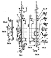
- Figures 1 to 4 illustrate a device implementing a typical process of the prior art for manufacturing such sleeves.
- Figure 1 is a view, in longitudinal section in the plane XZ or PXZ, of the device or production line (6) for manufacturing a sleeve (4) from a strip (1) wound in the form of a coil. The sleeve is then cut along a given length to obtain cylindrical skirts (41) to be assembled to the heads to obtain flexible tubes.
- FIG. 1e and FIG. 1f more particularly describe the strip (1) in said manufacturing line (6) and the embodiment of the sleeve by rolling and welding the edges of said strip (1).
- Figure 1e shows the strip and the sleeve in section in the plane PXZ.
- FIG. 1f illustrates, in the form of transverse sections through a YZ plane, at different abscissae, denoted from XA to XH along the X axis, the successive stages of the rolling of the strip (1), the overlapping of the edges (2 ) and (3) of said band and welding said edges.
- the document WO 01/60588 describes a method of manufacturing skirts of flexible tubes according to the preamble of claim 1.
- This manufacturing method comprises a deformation step up to the elastic limit of the flat strip. This deformation makes it possible to remove any ripples from the edges of the strip.
- the geometric configuration in which the edges of the strip are at the time of welding is not as stable as desired and the quality of the weld suffers. Even if it is possible to avoid visible defects on the same skirt, the width of the longitudinal weld can vary significantly from one skirt to another and it becomes difficult and expensive to control the strength of the weld. As the phenomenon increases with the speed of the tape, the productivity of the process is therefore limited.
- the subject of the invention is an improvement of the method of manufacturing laminated flexible tubes as described above, by introducing a step prior to the step of manufacturing the band described above.
- a step prior to the step of manufacturing the band described above Prior to its forming cylinder by folding and then facing or joining of its two longitudinal edges, it imposes stresses on the band such that it undergoes irreversible deformation after relaxation of stresses.
- This irreversible or plastic deformation is not necessarily very large but is typically greater than 1%. What matters is that this plasticization affects a sufficient part of the thickness of the strip to modify the state of residual stresses.
- thinning can be envisaged - for example by rolling - of at least 0.5%, preferably greater than 1%.
- embossing resulting in the creation of reliefs or troughs whose amplitude is between 1/30 and 5 times the value thickness, preferably between 1/15 and 5 times the thickness, more preferably between 1/10 and 3 times the thickness.
- the strip is passed in the gap between two substantially parallel cylinders, the average distance between the two cylinders being less than the initial thickness of the strip.
- these cylinders must exert on the band a force of between 2.5 and 500 newtons per millimeter of bandwidth.
- the effort required depends on the nature of the constituent material (s) of the strip. When it comprises more than 70% of thermoplastic material in volume, this effort decreases with the average temperature at which the band is and increases with the viscous behavior of the thermoplastic material.
- one of the rollers is preferably metallic, the other of elastomeric material or rubber.
- the metal roll is cooled so that when the strip, once out of the air gap between the rolls is either wound on a winder, or deformed to be shaped into a cylinder, its temperature is close to room temperature, typically below 40 ° C.
Landscapes
- Engineering & Computer Science (AREA)
- Mechanical Engineering (AREA)
- Physics & Mathematics (AREA)
- Thermal Sciences (AREA)
- Shaping Of Tube Ends By Bending Or Straightening (AREA)
Abstract
Description
- L'invention concerne le perfectionnement d'un procédé de fabrication de tubes souples destinés à stocker et à distribuer des produits liquides à pâteux. Ces tubes souples sont dits "laminés" car ils comprennent une tête et une jupe souple, elle-même obtenue à partir d'une bande dite "laminée", comprenant en général plusieurs couches plastiques ou métalliques. La jupe est obtenue par découpe dans un manchon cylindrique, lui-même obtenu par roulage d'une bande plane. Le roulage est effectué de telle sorte que la bande est mise en forme de cylindre, les bords de ladite bande étant mis en regard l'un de l'autre, en général avec un léger recouvrement, puis soudés entre eux. Une tête de tube est ensuite soudée à une extrémité de ladite jupe. La tête comporte un goulot avec un orifice de distribution du produit contenu dans le tube et une épaule reliant le goulot à ladite jupe. Le tube ainsi réalisé est ensuite livré au conditionneur , la tête en bas et l'orifice de distribution obturé - par exemple par une capsule vissée sur le goulot - pour que celui-ci remplisse le tube par l'extrémité restée ouverte du tube. Une fois le tube rempli, son extrémité ouverte est aplatie de façon à effectuer une soudure qui réunit les portions de paroi mises en vis-à-vis à la suite de l'aplatissement et qui scelle ainsi le produit conditionné (soudure dite transversale ou finale).
- On connaît déjà, par exemple par
FR 1 571 778 - Les figures 1 à 4 illustrent un dispositif mettant en oeuvre un procédé typique de l'art antérieur permettant de fabriquer de tels manchons.
- La figure 1 est une vue, en coupe longitudinale dans le plan XZ ou PXZ, du dispositif ou ligne de production (6) permettant de fabriquer un manchon (4) à partir d'une bande (1) enroulée sous forme de bobine. Le manchon est ensuite débité suivant une longueur donnée pour obtenir des jupes cylindriques (41) destinées à être assemblées à des têtes pour obtenir des tubes souples.
- Sur la figure 1e, on a repéré différents moyens de la ligne de production (6) selon la direction longitudinale X par leur abscisse X=XA à XF.
- Les figures 1a à 1d sont des vues en coupe selon le plan PXZ des différentes bandes mobiles (620, 640, 650 et 660) du dispositif (6) fermées sur elles-mêmes, positionnées les unes par rapport aux autres selon l'axe X, mais décalées selon l'axe Z de manière à les présenter séparément:
- figure 1a: bande mobile (620) solidaire du mandrin central (62), appelée "bande interne", représentée en coupe sur la figure 4, située au-dessous de la zone de recouvrement des bords 2 et 3 de la bande, et s'étendant de X=XD à X=XG, typiquement sur une longueur de 1,8 m environ.
- figure 1b : bande mobile (640), dite "bande externe chaude", située au-dessus de la zone de recouvrement des bords 2 et 3 de la bande, s'étendant de X=XE à X=XF, typiquement sur une longueur de 0,4 m environ
- figure 1c : bande mobile (650), dite "bande externe froide", située au-dessus de la zone de recouvrement des bords 2 et 3 de la bande, s'étendant de X=XF à X=XG, typiquement sur une longueur de 1 m environ.
- figure 1d : bande mobile (660), dite bande de transport, située au-dessous de la bande roulée et du manchon, entraînant le tube sur une longueur de 2,5 m environ, entre X=XB et X=XH,
- La figure 1e et la figure 1f décrivent plus particulièrement la bande (1) dans ladite ligne de fabrication (6) et la réalisation du manchon par roulage et soudage des bords de la dite bande (1). La figure 1e représente la bande et le manchon en coupe dans le plan PXZ. La figure 1f illustre, sous forme de coupes transversales par un plan YZ, en différentes abscisses, notées de XA à XH le long de l'axe X, les étapes successives du roulage de la bande (1), du chevauchement des bords (2) et (3) de ladite bande et du soudage desdits bords.
- Dans ce qui suit, relativement à la figure 1, nous indiquerons, d'amont vers l'aval, les différents moyens présents sur la ligne (6), outre les différentes bandes mobiles des figures 1a à 1e, certains de ces moyens n'étant pas représentés en tant que tels sur la figure 1 pour ne pas l'alourdir :
- a) en amont de X=XA, qui représente le point de la ligne (6) où la bande arrive plane et en position transversale correcte, c'est-à-dire avec son plan médian (100) comprenant l'axe longitudinal (40) fixe, se trouvent d'abord les moyens (10) d'approvisionnement en bande (1), typiquement un dévideur de bobine, puis un moyen de guidage latéral (60),
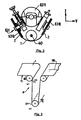
- puis, comme illustré de manière plus détaillée sur la figure 3, deux rouleaux de tension (61), avec un rouleau de tension amont (610) et un rouleau de tension aval (611), dont la différence de vitesse de rotation induit une tension dans la bande destinée à stabiliser ses bords ou rives en supprimant des ondulations latérales lorsqu'elles sont présentes. La figure 3 est une vue schématique d'un dispositif (61) comprenant deux rouleaux de tension (610) et (611), avec soit, les deux rouleaux étant de même diamètre comme illustré sur la figure 3, le second rouleau (611) tournant à une vitesse angulaire ω2 supérieure à celle ω1 du premier rouleau (610), soit, les vitesses angulaires étant voisines, le second rouleau (611) ayant un plus grand diamètre que le premier rouleau (610), de manière à ce que la vitesse linéaire de la bande (1) soit plus élevée en sortie du second rouleau que du premier rouleau. De ce fait, la bande (1) est soumise entre ces deux rouleaux à une tension longitudinale pouvant atteindre la limite élastique du matériau constituant la bande.
On a représenté la bande (1) en amont du rouleau (610) avec des irrégularités ou ondulations des bords, alors que, après mise sous tension de la bande, en aval du rouleau (611), la bande ne présente pas de bords irréguliers. Cette tension, typiquement comprise entre 0,3 et 0,8 fois la limite élastique du matériau formant la bande (1), est maintenue durant la formation du tube (4). - b) entre X=XA et X=XB, on trouve en général des moyens complémentaires permettant de mieux contrôler le positionnement de la bande sur l'axe Y. Un bon contrôle de la position transversale de la bande est en effet important si l'on veut obtenir une soudure longitudinale régulière car il faut maîtriser la configuration géométrique dans laquelle se trouvent les bords de la bande au moment de la soudure.
- c) au point X=XB, un roulette centrale (630) est mise en appui sur la bande (1) au niveau de son plan médian (100), de manière à commencer le roulage de cette bande selon un profil transversal représenté sur la figure 1 f.
- d) au point X=XC, les bords (2) et (3) de la bande sont engagés dans les gorges des roulettes à gorge (6310), la bande présentant alors un profil transversal représenté sur la figure 1f. La figure 2 représente, en coupe dans un plan PYZ, un dispositif (631) de guidage des bords (2,3) de la bande (1), à l'aide de deux roulettes à gorge (6310), les bords étant maintenus dans les gorges, ce dispositif (631) comprenant un support circulaire (6311) fixé lui- même au bâti de la ligne (6).
- e) entre X=XC et X=XD, se trouvent notamment des moyens (non représentés sur la figure 1) pour maintenir en position le mandrin central (62) et éventuellement pour poursuivre le roulage de la bande.
- f) entre X=XD et X=XE, des galets de roulage (632) et (633) sont appliqués latéralement, comme représenté sur la figures 4, de manière à rabattre les bords (2,3) de la bande. La figure 4 illustre par une coupe dans un plan PYZ le roulage de la bande (1) à l'aide des galets de roulage (632) et (633), galets qui présentent respectivement une surface concave (6320) et (6330) et un axe de rotation (6321) et (6331), de manière à mettre en regard les bords supérieur (2) et inférieur (3) en vue de leur soudure. Les axes (6321) et (6331) peuvent être verticaux ou inclinés - comme illustré sur la figure 4 - leur point de convergence situés du même côté que la zone de recouvrement, de façon à maintenir plus fermement les bords 2 et 3 en regard l'un de l'autre et à obtenir une géométrie de recouvrement la plus stable possible. Il est en effet essentiel que la configuration géométrique dans laquelle se trouvent les bords de la bande soit la plus stable possible au moment de la soudure. C'est notamment elle qui détermine la largeur de recouvrement, donc la largeur de la soudure visible.
- g) entre X=XE et X=XF, les bords sont maintenus superposés l'un sur l'autre (ou simplement accolés l'un contre l'autre, comme dans le procédé décrit dans
EP 0 627 982 (Karl Mägerle Lizenz )) grâce à un appui exercé par la bande externe chaude (640) sur la bande interne (620). Sous l'effet de cet appui, ces bords se soudent entre eux grâce à un apport thermique effectué à ce niveau, soit juste avant l'entrée dans la zone X= XE à XF, soit dans la zone X=XE à XF elle-même, par exemple en utilisant un inducteur (641) agissant directement sur la bande lorsque celle-ci est métalloplastique. - h) entre X= XF et X=XG, la soudure est refroidie pendant que le manchon reste soutenu intérieurement par le mandrin central (62). La zone de soudure est elle-même maintenue comprimée entre la bande mobile interne (620) et la bande externe froide (650) pendant tout ce trajet.
- i) Entre XG et XH, le manchon cylindrique ainsi obtenu sort de son dispositif de conformation (les bandes mobiles 620 et 650 et le mandrin central (62)) puis est débité (67) à la longueur voulue en jupes cylindriques (41).
- Le document
WO 01/60588 - Malgré toutes les précautions prises pour contrôler le positionnement latéral de la bande, la configuration géométrique dans laquelle se trouvent les bords de la bande au moment de la soudure n'est pas aussi stable que souhaité et la qualité de la soudure en pâtit. Même si l'on peut éviter des défauts visibles sur une même jupe, la largeur de la soudure longitudinale peut varier de façon importante d'une jupe à une autre et il devient difficile et coûteux de contrôler la solidité de la soudure. Le phénomène s'amplifiant avec la vitesse de défilement de la bande, la productivité du procédé est de ce fait limitée.
- De plus, en sortant de son dispositif de conformation (les bandes 620 et 650 et le mandrin central (62)), on constate que, dans un grand nombre de cas, notamment lorsque la bande d'origine comporte plus de 70% en volume de matière thermoplastique, le manchon perd sa forme parfaitement circulaire. Sa section prend en effet une forme en "goutte d'eau" telle que celle illustrée dans l'exemple présenté ci-après. Ceci est particulièrement préjudiciable pour les opérations ultérieures effectuées dans le cadre de la fabrication du tube souple. En premier lieu, lors de l'assemblage de la tête de tube sur une extrémité de la jupe, celle-ci coïncide mal avec l'extrémité circulaire de la tête moulée. Ensuite, l'autre extrémité de la jupe est une source ultérieure de problèmes puisque le conditionneur doit remplir le tube souple en introduisant une buse par cette extrémité ouverte de la jupe. Si cette extrémité ouverte n'est pas parfaitement circulaire, l'introduction automatique de la buse de remplissage peut être perturbée (collage de l'extrémité de la jupe sur la buse de remplissage par exemple), ce qui impose l'ajout de moyens coûteux de centrage et de calibrage pour atteindre les cadences de remplissage voulues. En dernier lieu, lorsque le tube est rempli, cette même extrémité fait l'objet d'une soudure finale qui est grandement facilitée si l'extrémité de la jupe présente une géométrie circulaire répétitive.
- La demanderesse a donc cherché à modifier ledit procédé de fabrication de façon à éviter de tels inconvénients.
- L'invention a pour objet une amélioration du procédé de fabrication de tubes souples laminés tel que décrit précédemment consistant à introduire une étape préalable à l'étape de fabrication de la bande décrite précédemment. Préalablement à sa mise en forme de cylindre par rabattement puis mise en regard ou accolement de ses deux bords longitudinaux, on impose à la bande des contraintes telles qu'elle subit une déformation irréversible après relâchement des contraintes. Cette déformation irréversible, ou plastique, n'est pas nécessairement très grande mais elle est typiquement supérieure à 1%. Ce qui compte, c'est que cette plastification affecte une partie suffisante de l'épaisseur de la bande pour modifier l'état de contraintes résiduelles.
- Pour déformer plastiquement la bande, on peut envisager un amincissement - par exemple par laminage -d'au moins 0,5%, de préférence supérieur à 1%. On peut également envisager un embossage se traduisant par la création de reliefs ou de creux dont l'amplitude est comprise entre 1/30 et 5 fois la valeur de l'épaisseur, de préférence entre 1/15 et 5 fois l'épaisseur, de préférence encore entre 1 /10 et 3 fois l'épaisseur.
- Selon une modalité préférée de l'invention, on fait passer la bande dans l'entrefer compris entre deux cylindres sensiblement parallèles, la distance moyenne entre les deux cylindres étant inférieure à l'épaisseur initiale de la bande. Typiquement, ces cylindres doivent exercer sur la bande un effort compris entre 2,5 et 500 newtons par millimètre de largeur de bande.
- Il s'agit en quelque sorte d'un calandrage simplifié, où le dispositif utilisé comporte un faible nombre de cylindres (par exemple limité à deux) et où lesdits cylindres ne sont pas forcément chauffés. Par la suite, nous appellerons cette opération "calandrage" ou, lorsque le terme est approprié, "embossage".
- L'effort nécessaire dépend de la nature du ou des matériaux constitutifs de la bande. Lorsque celle-ci comporte plus de 70% de matière thermoplastique en volume, cet effort diminue avec la température moyenne à laquelle se trouve la bande et augmente avec le comportement visqueux du matériau thermoplastique.
- Les cylindres peuvent être lisses et dans ce cas on impose un calandrage se traduisant par un amincissement plastique au moins égal à 0,5%, de préférence supérieur à 1%. Les cylindres peuvent également comporter des reliefs plus ou moins prononcés, permettant d'embosser la bande. L'amplitude du relief embossé est typiquement comprise entre un trentième et cinq fois l'épaisseur de la bande mais les meilleurs résultats sont obtenus avec des reliefs compris entre 1/10 et 3 fois l'épaisseur. L'effort à appliquer entre les cylindres est dans ce cas au moins égal à l'effort minimal nécessaire pour embosser la bande.
- De préférence, si le relief embossé ne couvre pas toute la surface de la bande, il doit être réparti régulièrement de façon à pouvoir enrouler la bande sous forme de bobine régulière. Si le décor embossé n'est pas réparti régulièrement, il est alors préférable d'effectuer l'embossage directement sur la ligne de fabrication des jupes, en plaçant les cylindres en amont du dispositif qui permet de mettre la bande en forme de cylindre, par exemple en amont de la roulette centrale (630) ou, mieux, en amont du moyen de guidage latéral de la bande (60). Dans le cas où le relief est régulièrement réparti sur toute la largeur de la bande, l'effet de l'embossage sur l'aptitude de la bande à être mise en forme de cylindre est tellement marqué que ledit moyen de guidage latéral de la bande peut dans certains cas être considéré comme superflu.
- Si la bande présente un comportement mécanique plastique prépondérant (aptitude à l'obtention d'une déformation irréversible sous faible contrainte), par exemple si elle comporte plus de 30% en volume d'un métal tel qu'un alliage d'aluminium, on peut effectuer soit un laminage, soit un embossage à température ambiante. Le laminage est réalisé avec un serrage entre cylindres tel que la limite élastique à l'ambiante dudit métal est atteinte: grossièrement, la déformation étant proche d'une déformation plane, l'effort de serrage entre cylindres doit se traduire, en l'absence d'effort de traction, par une contrainte normale voisine de 2/√3 fois la limite élastique. L'embossage est réalisé en appliquant un effort suffisant pour que les reliefs soient obtenus de façon irréversible.
- Si la bande comporte une grande quantité de matériau thermoplastique, typiquement plus de 70% en volume, il est alors préférable de prévoir en amont de l'entrée de la bande dans l'entrefer entre les cylindres une zone de chauffage suffisamment longue pour que la température moyenne dans l'épaisseur de la bande atteigne une température comprise entre 75 et 120°C et soit maintenue à la température visée pendant au moins 0,5 seconde, juste avant d'entrer en contact avec les cylindres.
- La bande comportant une grande quantité de matériau thermoplastique peut également comprendre des couches constituées de matériaux non thermoplastiques, tel que du papier, du métal ou encore des couches hétérogènes par exemple en matériaux non-tissés constitués de fibres comprimées thermiquement. Elle peut également comporter des couches en matière thermoplastique chargée de particules solides, typiquement en carbonate de calcium, en argile, en mica, etc... Elle doit toutefois comprendre au moins 70% de matériau thermoplastique en volume pour que l'effet bénéfique du traitement thermique préalable préconisé selon une modalité préférée de l'invention soit perceptible.
- Si le passage entre les rouleaux se traduit par un embossage, l'un des rouleaux est de préférence métallique, l'autre en matériau élastomérique ou en caoutchouc. De préférence également, le rouleau métallique est refroidi de telle sorte que lorsque la bande, une fois sortie de l'entrefer entre les cylindres est soit enroulée sur une bobineuse, soit déformée en vue d'être mise sous forme d'un cylindre, sa température est proche de la température ambiante, typiquement inférieure à 40°C.
- En général, la jupe du tube souple comporte un décor imprimé destiné à informer l'utilisateur du produit contenu par le tube. Dans le présent procédé de fabrication des tubes souples, le décor est imprimé sur la bande avant sa mise en forme de cylindre, par exemple avant ou au cours du passage de la bande dans l'entrefer compris entre les cylindres.
- Les cylindres peuvent en un tel cas correspondre aux cylindres employés pour imprimer le décor, par flexographie ou typographie directe par exemple. Dans les cas où l'on veut embosser la bande, le rouleau gravé permettant l'embossage peut également servir à encrer les creux embossés, ce qui donne des effets de décor particuliers ("print valley").
- Avec un telle étape préalable, la bande présente un comportement mécanique tel que son aptitude à être mise en forme de cylindre est grandement améliorée et que le manchon obtenu ne présente plus une section en forme de goutte d'eau (il présente donc une meilleure circularité) lorsqu'il sort de son dispositif de conformation (bande interne (620), bande externe froide (650) et mandrin central (62)). La meilleure aptitude de la bande à être mise en forme de cylindre est due à la présence moins fréquente d'ondulations latérales sur les bords de ladite bande et à une rigidité élastique de ladite bande plus importante dans le sens longitudinal et plus homogène dans le sens transversal.
- En effet, l'étape préalable selon l'invention est une opération de calandrage / embossage qui a pour effet de régulariser la forme de la bande (moins d'ondulations latérales) et de diminuer l'amplitude des contraintes résiduelles régnant dans ladite bande. Cela a pour effet d'uniformiser le comportement élastique de la bande et, surtout lorsqu'il s'agit d'un embossage créant des reliefs et/ou des creux régulièrement répartis, d'augmenter la rigidité de la bande, autant da ns le sens long que dans le sens travers.
- Ainsi, sous l'effet des efforts de flexion, la bande présente un rayon de courbure plus homogène dans toute sa largeur. De plus, ces efforts de flexion étant imposés localement (par la roulette centrale (630), par les moyens permettant de poursuivre le roulage de la bande entre X=XC et X=XD, par les galets de roulage (632) et (633)), la bande, plus rigide dans le sens longitudinal conserve mieux la forme imposée en dehors de la zone d'application desdits efforts. Tout ceci permet de mieux guider les bords de la bande au cours du roulage jusqu'à ce qu'ils soient mis en regard (ou accolés) en vue de leur soudure. On obtient donc une géométrie de recouvrement plus stable et la soudure réalisée est de meilleure qualité.
- Enfin, l'uniformisation de la rigidité dans le sens travers et la diminution des contraintes résiduelles sont une explication possible du fait que le manchon présente une meilleure circularité après sa sortie du dispositif de conformation.
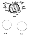
- Comme nous l'avons vu, les figures 1 à 4 illustrent un dispositif apte à mettre une bande en forme de manchon cylindrique. La figure 5 illustre deux sections de manchons. La figure 5a illustre une section en forme de goutte d'eau, relative à un manchon qui n'a pas subi le traitement préalable selon l'invention. La figure 5b est relative à un manchon qui a subi ledit traitement; elle présente une meilleure circularité.
- Une bande métalloplastique d'épaisseur globale 280 µm, de largeur 225 mm, présente la structure suivante:
- PE.BD (90 µm)/EAA (25 µm)/aluminium (15µm)/EAA (20 µm)/PE.BD (130 µm)
- avec PE.BD= polyéthylène basse densité
EAA= copolymère (éthylène acide acrylique) - La bande se présente sous forme de bobine. Une première partie de la bande est utilisée sans avoir subi le traitement préalable selon l'invention. Elle est utilisée pour réaliser un manchon cylindrique comme il a été décrit précédemment et illustré dans les figures 1 à 4. Sa vitesse de défilement est de l'ordre de 30 m/mn.
- Après avoir dévidé l'ensemble de la bobine, soit environ 1000 m, on constate que le manchon sort avec une soudure longitudinale de largeur variable, celle-ci variant entre 1,6 et 2,5 mm. Sa section sort du dispositif de conformation avec une forme en goutte d'eau du type de celle illustrée en figure 5a. L'ovalisation est mesurée en comparant les valeurs de deux diamètres orthogonaux L et P, l'axe L choisi correspondant au diamètre maximum. Sur la partie gauche du tableau 1, on observe que la moyenne du rapport entre ces diamètres est 0,95, avec un écart-type de 0,02.
- Une autre partie de la même bande subit préalablement à sa mise en forme de cylindre un embossage à la température ambiante. Le dispositif d'embossage comprend un cylindre embosseur gravé avec des reliefs de hauteur comprise entre 50 et 100 µm et un cylindre d'appui en élastomère. L'effort appliqué sur le cylindre embosseur est de l'ordre de 200 kN.
- Comme dans l'essai témoin décrit précédemment, la bande défile à une vitesse de l'ordre de 30 m/mn. Après embossage, la bande qui présente sur toute sa largeur un aspect "cuir" est enroulée pour former une bobine.
- La bobine est ensuite utilisée pour réaliser un manchon cylindrique en suivant le procédé décrit précédemment. On constate que la soudure réalisée est de meilleure qualité que lorsque la bande n'est pas embossée; sa largeur varie mais l'amplitude de variation est nettement plus faible: entre 1,8 et 2,2 mm. Sa section sort du dispositif de conformation avec une forme circulaire du type de celle illustrée en figure 5b. Sur la partie droite du tableau 1, on observe que la moyenne du rapport entre ces diamètres est 0,99, avec un écart-type de 0,02
Tableau 1 
MESURES D'OVALISATION Tubes non embossés Tubes embossés Mesure diamètre suivant axe L Mesure diamètre suivant axe P Rapport P/L Mesure diamètre suivant axe L Mesure diamètre suivant axe P Rapport P/L Moyenne 36,45 34,55 0,95 35,5 35 0,99 Ecart-Type 0,36 0,36 0,02 0,46 0,26 0,02 - D'autre part, on constate une amélioration des propriétés dites de "rebound". Le "rebound" est caractéristique de l'aptitude de la jupe de tube à retrouver sa forme cylindrique après une pressée. Plus cette valeur est élevée, meilleure est cette aptitude. On la mesure avec des essais de flexion standardisés faisant appel à la méthode de la lame d'appui: une moitié de jupe est découpée suivant un plan diamétral puis encastrée par ses extrémités sur un support. On enfonce le l'arche ainsi formée à l'aide d'un dispositif axial venant en appui sur la génératrice du sommet de l'arche (MD). D'autres essais ont été effectués sur une arche formée avec la demi-jupe fléchie dans une direction perpendiculaire à la direction axiale (CMD). On mesure la valeur de l'effort d'enfoncement correspondant à une déflexion donnée. Le tableau 2 suivant montre la valeur de l'effort (en N) correspondant à une déflexion de 5mm pour une jupe de 35mm de diamètre
Tableau 2 MESURES DE REBOUND Tubes non embossés Tubes embossés MD 1,1 MD 1,6 CMD 1,0 CMD 1,4 - Une bande entièrement plastique d'épaisseur globale 280 µm, de largeur 225 mm, présente la structure suivante:
- PE.BD (15 µm)/ PEHD (60 µm)/ PE.BD (75 µm) /EMA (10 µm)/ EVOH (20 µm)/ EMA (10 µm)/PE.BD (90 µm)
avec PE.BD= polyéthylène basse densité
PE.HD= polyéthylène haute densité
EAA= copolymère (éthylène acide acrylique) - La bande se présente sous forme de bobine. Une première partie de la bande est utilisée sans avoir subi le traitement préalable selon l'invention. Elle est utilisée pour réaliser un manchon cylindrique comme il a été décrit précédemment et illustré dans les figures 1 à 4.
- Après avoir dévidé l'ensemble de la bobine (environ 1000 m), on constate que le manchon sort avec une soudure longitudinale de largeur variable, celle-ci variant entre 1,4 et 2,6 mm. Sa section sort du dispositif de conformation avec une forme en goutte d'eau du type de celle illustrée en figure 5a. L'ovalisation est mesurée en comparant les valeurs de deux diamètres orthogonaux L et P, l'axe L choisi correspondant au diamètre maximum. Sur la partie gauche du tableau 3, on observe que la moyenne du rapport entre ces diamètres est 0,93, avec un écart-type de 0,02.
Tableau 3 
MESURES D'OVALISATION Tubes non embossés Tubes embossés Mesure diamètre suivant axe L Mesure diamètre suivant axe P Rapport P/L Mesure diamètre suivant axe L Mesure diamètre suivant axe P Rapport P/L Moyenne 36,65 34,15 0,93 35,45 35,05 0,99 Ecart-Type 0,41 0,41 0,02 0,50 0,28 0,02 - Une autre partie de la même bande subit préalablement à sa mise en forme de cylindre un embossage destiné à lui donner un relief en "nid d'abeille" avec des motifs hexagonaux en creux de profondeur sensiblement égale à 70 µm. En amont du dispositif d'embossage, la bande passe au défilé dans un tunnel de chauffage. Elle y est portée à une température de 80°C est y est maintenue pendant au moins 0,6 seconde avant d'entrer dans l'entrefer du dispositif d'embossage. Le dispositif d'embossage comprend un cylindre embosseur gravé et un cylindre d'appui en élastomère. L'effort appliqué sur le cylindre embosseur est de l'ordre de 170 kN.
- Le cylindre embosseur métallique est refroidi avec un circuit d'eau. De la sorte, la bande arrive sur la bobineuse à une température voisine de la température ambiante, en tout cas inférieure à 40°C.
- La bobine est ensuite utilisée pour réaliser un manchon cylindrique. On constate que la soudure réalisée est de meilleure qualité; sa largeur varie entre 1,8 et 2,2 mm. Sa section sort du dispositif de conformation avec une forme circulaire.
- D'autre part, on constate une amélioration des propriétés dites de "rebound" (voir description dans l'exemple 1). Le tableau 4 suivant montre la valeur de l'effort (en N) correspondant à une déflexion de 5mm pour une jupe de 35mm de diamètre
Tableau 4 MESURES DE REBOUND Tubes non embossés Tubes embossés MD 1,7 MD 2,4 CMD 1,4 CMD 2,4
Claims (10)
- Procédé de fabrication de jupes (41) de tubes souples comprenant une étape de fabrication d'un manchon (4) cylindrique à partir d'une bande (1) plane comprenant une ou plusieurs couches plastiques ou métalliques suivie d'une étape où ledit manchon (4) cylindrique est découpé à longueur voulue pour obtenir lesdites jupe (41), caractérisé en ce qu'il comprend une étape préalable à l'étape de fabrication du manchon cylindrique, dans laquelle on impose une déformation plastique à ladite bande (1).
- Procédé selon la revendication 1 dans lequel on fait passer ladite bande (1) entre deux outillages mobiles l'un par rapport à l'autre et dont le rapprochement offre à ladite bande un entrefer de dimension inférieure à l'épaisseur initiale de la bande.
- Procédé selon la revendication 2 dans lequel on applique un effort entre lesdits outillages tel que la bande sort dudit entrefer avec un amincissement plastique supérieur à 0,5%, de préférence supérieur à 1 %.
- Procédé selon la revendication 2 ou 3 dans lequel on applique un effort entre lesdits outillages tel que la bande sortant dudit entrefer présente un décor embossé comportant des reliefs ou des creux dont l'amplitude est comprise entre le trentième et cinq fois l'épaisseur de ladite bande, de préférence entre le quinzième et cinq fois l'épaisseur, de préférence encore entre le dixième et 3 fois l'épaisseur.
- Procédé selon l'une quelconque des revendications 2 à 4 dans lequel lesdits outillages mobiles sont des cylindres sensiblement parallèles, dont l'un au moins possède des reliefs gravés, de telle sorte que la bande ressort embossée après être passée entre lesdits cylindres.
- Procédé selon l'une quelconque des revendications 2 à 5 dans lequel la bande est comprimée entre lesdits outillages avec un effort compris entre 2,5 et 500 newtons par millimètre de largeur de bande.
- Procédé selon l'une quelconque des revendications 1 à 6, dans lequel ladite bande est portée à une température comprise entre 75°C et 120°C avant d'entrer en contact avec lesdits outillages.
- Procédé selon la revendication 7 dans lequel ladite bande est maintenue à ladite température pendant au moins 1/2 seconde avant d'entrer en contact avec lesdits cylindres.
- Procédé selon l'une quelconque des revendications 5 à 8, dans lequel au moins un cylindre est refroidi de telle sorte que lorsque la bande, une fois sortie de l'entrefer entre les cylindres, est soit enroulée sur une bobineuse, soit déformée en vue d'être mise sous forme d'un cylindre, sa température est proche de la température ambiante, typiquement inférieure à 40°C.
- Procédé selon l'une quelconque des revendications 5 à 9 dans lequel le cylindre gravé est également utilisé pour imprimer un décor sur ladite bande.
Applications Claiming Priority (3)
| Application Number | Priority Date | Filing Date | Title |
|---|---|---|---|
| FR0213352 | 2002-10-25 | ||
| FR0213352A FR2846275B1 (fr) | 2002-10-25 | 2002-10-25 | Perfectionnement d'un procede de fabrication de tubes souples plastiques ou metalloplastiques |
| PCT/FR2003/003105 WO2004039561A1 (fr) | 2002-10-25 | 2003-10-21 | Procede de fabrication de tubes souples plastiques ou metalloplastiques |
Publications (2)
| Publication Number | Publication Date |
|---|---|
| EP1565303A1 EP1565303A1 (fr) | 2005-08-24 |
| EP1565303B1 true EP1565303B1 (fr) | 2007-08-01 |
Family
ID=32088267
Family Applications (1)
| Application Number | Title | Priority Date | Filing Date |
|---|---|---|---|
| EP03778414A Expired - Lifetime EP1565303B1 (fr) | 2002-10-25 | 2003-10-21 | Procede de fabrication de tubes souples plastiques ou metalloplastiques |
Country Status (15)
| Country | Link |
|---|---|
| US (1) | US20060016501A1 (fr) |
| EP (1) | EP1565303B1 (fr) |
| JP (1) | JP2006503737A (fr) |
| CN (1) | CN100374281C (fr) |
| AR (1) | AR041682A1 (fr) |
| AU (1) | AU2003285415A1 (fr) |
| BR (1) | BR0315638A (fr) |
| CA (1) | CA2502828A1 (fr) |
| DE (1) | DE60315341T2 (fr) |
| ES (1) | ES2293049T3 (fr) |
| FR (1) | FR2846275B1 (fr) |
| MX (1) | MXPA05004264A (fr) |
| PL (1) | PL375206A1 (fr) |
| RU (1) | RU2323825C2 (fr) |
| WO (1) | WO2004039561A1 (fr) |
Families Citing this family (9)
| Publication number | Priority date | Publication date | Assignee | Title |
|---|---|---|---|---|
| JP2006264005A (ja) * | 2005-03-23 | 2006-10-05 | Daiwa Can Co Ltd | ラミネートチューブ容器の製造方法 |
| FR2908345B1 (fr) * | 2006-11-10 | 2009-11-27 | Cebal Sas | Perfectionnement d'un procede de fabrication de tubes souples lamines |
| EP2036697A1 (fr) * | 2007-09-13 | 2009-03-18 | Aisapack Holding SA | Procédé de fabrication de tubes par soudage |
| EP2276622B1 (fr) | 2008-04-10 | 2016-12-21 | Aisapack Holding SA | Procédé de fabrication de tubes par soudage |
| US8811911B2 (en) * | 2010-07-02 | 2014-08-19 | Htc Corporation | Radio-frequency processing device and method and related wireless communication device |
| DE202011004017U1 (de) | 2011-03-16 | 2011-08-11 | Linhardt Gmbh & Co. Kg | Tube |
| DE102011051108A1 (de) * | 2011-06-16 | 2012-12-20 | Packsys Global (Switzerland) Ltd. | Verfahren zum Herstellen von Rohrkörpern für Verpackungstuben sowie Verpackungstube mit Rohrkörper |
| EP2829381A1 (fr) * | 2013-07-25 | 2015-01-28 | PackSys Global (Switzerland) Ltd. | Dispositif de soudage pour la fabrication de corps tubulaires |
| CN108296663A (zh) * | 2018-03-28 | 2018-07-20 | 中山市德宇自动化科技有限公司 | 一种软管材焊接成型机 |
Family Cites Families (24)
| Publication number | Priority date | Publication date | Assignee | Title |
|---|---|---|---|---|
| US2605018A (en) * | 1949-10-05 | 1952-07-29 | Santy M Croce | Dispensing tube |
| GB698773A (en) * | 1950-07-27 | 1953-10-21 | Rene Bornand | Improved method and apparatus for producing flexible tubing |
| GB795015A (en) * | 1955-07-08 | 1958-05-14 | Hermorion Ltd | Improvements in devices for sealing a longitudinal overlapping seam |
| US3060515A (en) * | 1960-06-10 | 1962-10-30 | Nat Distillers Chem Corp | Method for conditioning thin sheets of a thermoplastic material to improve windability |
| GB957880A (en) * | 1962-05-16 | 1964-05-13 | Tuyaux Flexibles Rudolph | Improvements in and relating to flexible tubes |
| FR1528456A (fr) * | 1967-06-22 | 1968-06-07 | United Glass Ltd | Récipient tubulaire repliable à base de matière thermoplastique et procédé pourson obtention |
| US3575769A (en) * | 1968-03-27 | 1971-04-20 | American Can Co | Tube side seaming method and apparatus |
| IL48810A (en) * | 1976-01-08 | 1977-11-30 | Gilead Gideon | Hose conduits for drip or trickle emission |
| SE445031B (sv) * | 1984-10-02 | 1986-05-26 | Akerlund & Rausing Ab | Forpackningstub samt forfarande och anordning for tillverkning derav |
| ZA865689B (en) * | 1985-07-31 | 1987-03-25 | Ross Leslie Palmer | Manufacture of roll formed and coated articles |
| US4781966A (en) * | 1986-10-15 | 1988-11-01 | Kimberly-Clark Corporation | Spunlaced polyester-meltblown polyetherester laminate |
| CH682734A5 (de) * | 1991-02-05 | 1993-11-15 | Maegerle Karl Lizenz | Vorrichtung zur Herstellung von Rohrkörpern. |
| CH683510A5 (de) * | 1991-06-28 | 1994-03-31 | Maegerle Karl Lizenz | Verfahren zur Herstellung einer Schweissnaht für Tubenrohre. |
| US5720913A (en) * | 1992-08-11 | 1998-02-24 | E. Khashoggi Industries | Methods for manufacturing sheets from hydraulically settable compositions |
| US5800647A (en) * | 1992-08-11 | 1998-09-01 | E. Khashoggi Industries, Llc | Methods for manufacturing articles from sheets having a highly inorganically filled organic polymer matrix |
| JPH07258992A (ja) * | 1994-03-17 | 1995-10-09 | Nippon Paper Ind Co Ltd | 製紙用カレンダ装置 |
| US5634595A (en) * | 1994-07-19 | 1997-06-03 | T-Systems International, Inc. | Drip irrigation hose and method for its manufacture |
| US5693403A (en) * | 1995-03-27 | 1997-12-02 | Kimberly-Clark Worldwide, Inc. | Embossing with reduced element height |
| FR2774707B1 (fr) * | 1998-02-06 | 2000-04-07 | Fort James France | Papier absorbant a usage domestique |
| US6554963B1 (en) * | 1998-11-02 | 2003-04-29 | Albany International Corp. | Embossed fabrics and method of making the same |
| US6348131B1 (en) * | 1999-11-12 | 2002-02-19 | Fort James Corporation | Multi-ply embossed absorbent paper products |
| FR2805198A1 (fr) * | 2000-02-17 | 2001-08-24 | Cebal | Procede de fabrication de tubes par soudure au laser |
| US6832546B2 (en) * | 2001-12-18 | 2004-12-21 | Sca Hygiene Products Gmbh | Embossing device |
| ATE516405T1 (de) * | 2002-01-29 | 2011-07-15 | Metso Paper Inc | Kalander zur verarbeitung einer gegebenenfalls beschichteten faserstoffbahn |
-
2002
- 2002-10-25 FR FR0213352A patent/FR2846275B1/fr not_active Expired - Fee Related
-
2003
- 2003-10-21 PL PL03375206A patent/PL375206A1/xx unknown
- 2003-10-21 MX MXPA05004264A patent/MXPA05004264A/es not_active Application Discontinuation
- 2003-10-21 EP EP03778414A patent/EP1565303B1/fr not_active Expired - Lifetime
- 2003-10-21 BR BR0315638-9A patent/BR0315638A/pt not_active IP Right Cessation
- 2003-10-21 AR ARP030103829A patent/AR041682A1/es not_active Application Discontinuation
- 2003-10-21 ES ES03778414T patent/ES2293049T3/es not_active Expired - Lifetime
- 2003-10-21 CN CNB2003801040788A patent/CN100374281C/zh not_active Expired - Fee Related
- 2003-10-21 AU AU2003285415A patent/AU2003285415A1/en not_active Abandoned
- 2003-10-21 RU RU2005115864/12A patent/RU2323825C2/ru not_active IP Right Cessation
- 2003-10-21 DE DE60315341T patent/DE60315341T2/de not_active Expired - Fee Related
- 2003-10-21 CA CA002502828A patent/CA2502828A1/fr not_active Abandoned
- 2003-10-21 WO PCT/FR2003/003105 patent/WO2004039561A1/fr not_active Ceased
- 2003-10-21 JP JP2004547700A patent/JP2006503737A/ja not_active Abandoned
- 2003-10-21 US US10/532,002 patent/US20060016501A1/en not_active Abandoned
Also Published As
| Publication number | Publication date |
|---|---|
| RU2323825C2 (ru) | 2008-05-10 |
| AU2003285415A1 (en) | 2004-05-25 |
| BR0315638A (pt) | 2005-08-23 |
| US20060016501A1 (en) | 2006-01-26 |
| WO2004039561A1 (fr) | 2004-05-13 |
| CN1717311A (zh) | 2006-01-04 |
| MXPA05004264A (es) | 2005-07-05 |
| RU2005115864A (ru) | 2006-01-20 |
| FR2846275A1 (fr) | 2004-04-30 |
| AR041682A1 (es) | 2005-05-26 |
| FR2846275B1 (fr) | 2004-12-10 |
| CN100374281C (zh) | 2008-03-12 |
| DE60315341T2 (de) | 2008-04-17 |
| ES2293049T3 (es) | 2008-03-16 |
| EP1565303A1 (fr) | 2005-08-24 |
| JP2006503737A (ja) | 2006-02-02 |
| DE60315341D1 (de) | 2007-09-13 |
| CA2502828A1 (fr) | 2004-05-13 |
| PL375206A1 (en) | 2005-11-28 |
Similar Documents
| Publication | Publication Date | Title |
|---|---|---|
| EP2188110B1 (fr) | Procédé de fabrication de tubes par soudage | |
| CA2517626C (fr) | Procede de fabrication en continu de tubes en matiere plastique avec etirage bi-axial et ligne de fabrication pour ce procede | |
| EP3131738B1 (fr) | Procédé et dispositif d'extrusion et étiquetage d'un tube d'emballage | |
| EP1565303B1 (fr) | Procede de fabrication de tubes souples plastiques ou metalloplastiques | |
| EP1268158A1 (fr) | Procede et ligne de fabrication en continu de tubes en matiere plastique avec etirage bi-axial, et tube en matiere plastique obtenu | |
| EP3512684B1 (fr) | Procédé et dispositif d'extrusion et d'étiquetage d'un produit cylindrique | |
| EP2276622B1 (fr) | Procédé de fabrication de tubes par soudage | |
| EP1679265A1 (fr) | Tube à section non-circulaire, son procédé de fabrication et dispositif pour sa mise en oeuvre | |
| EP2459360A1 (fr) | Procédé et dispositif pour souder un emballage plastique tubulaire et un emballage ainsi obtenu | |
| FR2805198A1 (fr) | Procede de fabrication de tubes par soudure au laser | |
| FR2933898A1 (fr) | Procede de formage de profiles de section angulaire et dispositif pour la mise en oeuvre de ce procede | |
| EP0366773B1 (fr) | Procede et appareil pour enduire de caoutchouc des fils deroules en parallele et produire ainsi une nappe | |
| EP2933092A1 (fr) | Procédé et dispositif d'extrusion et étiquetage d'un tube d'emballage | |
| FR2688738A1 (fr) | Procede de fabrication d'un ou de plusieurs profiles en matiere flexible, en particulier en papier, en carton, en materiaux composites ou analogues et dispositif pour la mise en óoeuvre de ce procede. | |
| FR3036646A1 (fr) | Jupe de tube decoree avec une soudure laterale esthetique | |
| BE560830A (fr) | ||
| CH347422A (fr) | Procédé de fabrication de sachets en matière plastique, machine pour la mise en oeuvre du procédé et sachet ou série de sachets obtenu par ce procédé | |
| FR2763018A1 (fr) | Carton ondule rigide | |
| EP3061595A1 (fr) | Procédé de fabrication de profilé creux en matériaux composites | |
| FR2806957A1 (fr) | Procede et ligne pour fabriquer en continu des tubes en matiere plastique avec etirage bi-axial, et tube en matiere plastique obtenu | |
| CH420954A (fr) | Procédé pour la fabrication d'une pièce buccale de cigarette, pièce ainsi obtenue, et appareil pour la mise en oeuvre de ce procédé | |
| BE484438A (fr) | ||
| BE489997A (fr) | ||
| FR2617759A1 (fr) | Installation pour la fabrication de films minces en matiere plastique d'epaisseur constante a partir d'une gaine tubulaire | |
| BE556727A (fr) |
Legal Events
| Date | Code | Title | Description |
|---|---|---|---|
| PUAI | Public reference made under article 153(3) epc to a published international application that has entered the european phase |
Free format text: ORIGINAL CODE: 0009012 |
|
| 17P | Request for examination filed |
Effective date: 20050331 |
|
| AK | Designated contracting states |
Kind code of ref document: A1 Designated state(s): AT BE BG CH CY CZ DE DK EE ES FI FR GB GR HU IE IT LI LU MC NL PT RO SE SI SK TR |
|
| AX | Request for extension of the european patent |
Extension state: AL LT LV MK |
|
| DAX | Request for extension of the european patent (deleted) | ||
| RBV | Designated contracting states (corrected) |
Designated state(s): DE ES FR GB IT |
|
| GRAP | Despatch of communication of intention to grant a patent |
Free format text: ORIGINAL CODE: EPIDOSNIGR1 |
|
| GRAS | Grant fee paid |
Free format text: ORIGINAL CODE: EPIDOSNIGR3 |
|
| GRAA | (expected) grant |
Free format text: ORIGINAL CODE: 0009210 |
|
| AK | Designated contracting states |
Kind code of ref document: B1 Designated state(s): DE ES FR GB IT |
|
| REG | Reference to a national code |
Ref country code: GB Ref legal event code: FG4D Free format text: NOT ENGLISH |
|
| REF | Corresponds to: |
Ref document number: 60315341 Country of ref document: DE Date of ref document: 20070913 Kind code of ref document: P |
|
| GBT | Gb: translation of ep patent filed (gb section 77(6)(a)/1977) |
Effective date: 20071025 |
|
| PGFP | Annual fee paid to national office [announced via postgrant information from national office to epo] |
Ref country code: DE Payment date: 20071130 Year of fee payment: 5 Ref country code: ES Payment date: 20071026 Year of fee payment: 5 |
|
| PGFP | Annual fee paid to national office [announced via postgrant information from national office to epo] |
Ref country code: IT Payment date: 20071026 Year of fee payment: 5 |
|
| REG | Reference to a national code |
Ref country code: ES Ref legal event code: FG2A Ref document number: 2293049 Country of ref document: ES Kind code of ref document: T3 |
|
| PGFP | Annual fee paid to national office [announced via postgrant information from national office to epo] |
Ref country code: GB Payment date: 20071029 Year of fee payment: 5 |
|
| PLBE | No opposition filed within time limit |
Free format text: ORIGINAL CODE: 0009261 |
|
| STAA | Information on the status of an ep patent application or granted ep patent |
Free format text: STATUS: NO OPPOSITION FILED WITHIN TIME LIMIT |
|
| 26N | No opposition filed |
Effective date: 20080506 |
|
| REG | Reference to a national code |
Ref country code: FR Ref legal event code: ST Effective date: 20080630 |
|
| PG25 | Lapsed in a contracting state [announced via postgrant information from national office to epo] |
Ref country code: FR Free format text: LAPSE BECAUSE OF NON-PAYMENT OF DUE FEES Effective date: 20071031 |
|
| GBPC | Gb: european patent ceased through non-payment of renewal fee |
Effective date: 20081021 |
|
| PG25 | Lapsed in a contracting state [announced via postgrant information from national office to epo] |
Ref country code: IT Free format text: LAPSE BECAUSE OF NON-PAYMENT OF DUE FEES Effective date: 20081021 Ref country code: DE Free format text: LAPSE BECAUSE OF NON-PAYMENT OF DUE FEES Effective date: 20090501 |
|
| PG25 | Lapsed in a contracting state [announced via postgrant information from national office to epo] |
Ref country code: GB Free format text: LAPSE BECAUSE OF NON-PAYMENT OF DUE FEES Effective date: 20081021 |
|
| REG | Reference to a national code |
Ref country code: ES Ref legal event code: FD2A Effective date: 20081022 |
|
| PG25 | Lapsed in a contracting state [announced via postgrant information from national office to epo] |
Ref country code: ES Free format text: LAPSE BECAUSE OF NON-PAYMENT OF DUE FEES Effective date: 20081022 |