EP1564741A1 - Methode Defektmanagementinformationen zu setzen, Datenaufnahmemethode, Computerprogramm, computer-lesbares Aufzeichnungsmedium und Informationsaufzeichnungsgerät, das mehrere Datenarten für unterschiedliche Nutzungsarten richtig auf dem gleichen Informationsaufzeichnungsgerät aufnimmt - Google Patents
Methode Defektmanagementinformationen zu setzen, Datenaufnahmemethode, Computerprogramm, computer-lesbares Aufzeichnungsmedium und Informationsaufzeichnungsgerät, das mehrere Datenarten für unterschiedliche Nutzungsarten richtig auf dem gleichen Informationsaufzeichnungsgerät aufnimmt Download PDFInfo
- Publication number
- EP1564741A1 EP1564741A1 EP05250420A EP05250420A EP1564741A1 EP 1564741 A1 EP1564741 A1 EP 1564741A1 EP 05250420 A EP05250420 A EP 05250420A EP 05250420 A EP05250420 A EP 05250420A EP 1564741 A1 EP1564741 A1 EP 1564741A1
- Authority
- EP
- European Patent Office
- Prior art keywords
- area
- information
- recording
- data
- defect management
- Prior art date
- Legal status (The legal status is an assumption and is not a legal conclusion. Google has not performed a legal analysis and makes no representation as to the accuracy of the status listed.)
- Ceased
Links
- 238000000034 method Methods 0.000 title claims abstract description 209
- 230000007547 defect Effects 0.000 title claims abstract description 147
- 238000004590 computer program Methods 0.000 title claims description 18
- 230000008569 process Effects 0.000 claims abstract description 178
- 238000001514 detection method Methods 0.000 claims abstract description 50
- 230000007246 mechanism Effects 0.000 claims abstract description 31
- 238000012795 verification Methods 0.000 claims description 57
- 230000002950 deficient Effects 0.000 claims description 45
- 230000000007 visual effect Effects 0.000 claims 2
- 230000003287 optical effect Effects 0.000 description 116
- 238000011112 process operation Methods 0.000 description 92
- 238000007726 management method Methods 0.000 description 67
- 239000004065 semiconductor Substances 0.000 description 12
- 238000010586 diagram Methods 0.000 description 9
- 238000012545 processing Methods 0.000 description 3
- 230000004044 response Effects 0.000 description 3
- 238000012937 correction Methods 0.000 description 2
- 238000005516 engineering process Methods 0.000 description 2
- 239000000284 extract Substances 0.000 description 2
- 230000006870 function Effects 0.000 description 2
- 230000007175 bidirectional communication Effects 0.000 description 1
- 230000005540 biological transmission Effects 0.000 description 1
- 238000004364 calculation method Methods 0.000 description 1
- 230000006854 communication Effects 0.000 description 1
- 238000004891 communication Methods 0.000 description 1
- 238000013144 data compression Methods 0.000 description 1
- 238000013523 data management Methods 0.000 description 1
- 238000012986 modification Methods 0.000 description 1
- 230000004048 modification Effects 0.000 description 1
- 230000009466 transformation Effects 0.000 description 1
Images










Classifications
-
- G—PHYSICS
- G11—INFORMATION STORAGE
- G11B—INFORMATION STORAGE BASED ON RELATIVE MOVEMENT BETWEEN RECORD CARRIER AND TRANSDUCER
- G11B20/00—Signal processing not specific to the method of recording or reproducing; Circuits therefor
- G11B20/10—Digital recording or reproducing
- G11B20/18—Error detection or correction; Testing, e.g. of drop-outs
- G11B20/1883—Methods for assignment of alternate areas for defective areas
-
- G—PHYSICS
- G11—INFORMATION STORAGE
- G11B—INFORMATION STORAGE BASED ON RELATIVE MOVEMENT BETWEEN RECORD CARRIER AND TRANSDUCER
- G11B20/00—Signal processing not specific to the method of recording or reproducing; Circuits therefor
- G11B20/10—Digital recording or reproducing
- G11B20/12—Formatting, e.g. arrangement of data block or words on the record carriers
- G11B20/1217—Formatting, e.g. arrangement of data block or words on the record carriers on discs
-
- G—PHYSICS
- G11—INFORMATION STORAGE
- G11B—INFORMATION STORAGE BASED ON RELATIVE MOVEMENT BETWEEN RECORD CARRIER AND TRANSDUCER
- G11B20/00—Signal processing not specific to the method of recording or reproducing; Circuits therefor
- G11B20/10—Digital recording or reproducing
- G11B20/18—Error detection or correction; Testing, e.g. of drop-outs
- G11B20/1816—Testing
-
- G—PHYSICS
- G11—INFORMATION STORAGE
- G11B—INFORMATION STORAGE BASED ON RELATIVE MOVEMENT BETWEEN RECORD CARRIER AND TRANSDUCER
- G11B20/00—Signal processing not specific to the method of recording or reproducing; Circuits therefor
- G11B20/10—Digital recording or reproducing
- G11B20/12—Formatting, e.g. arrangement of data block or words on the record carriers
- G11B2020/1264—Formatting, e.g. arrangement of data block or words on the record carriers wherein the formatting concerns a specific kind of data
- G11B2020/1265—Control data, system data or management information, i.e. data used to access or process user data
- G11B2020/1267—Address data
-
- G—PHYSICS
- G11—INFORMATION STORAGE
- G11B—INFORMATION STORAGE BASED ON RELATIVE MOVEMENT BETWEEN RECORD CARRIER AND TRANSDUCER
- G11B20/00—Signal processing not specific to the method of recording or reproducing; Circuits therefor
- G11B20/10—Digital recording or reproducing
- G11B20/12—Formatting, e.g. arrangement of data block or words on the record carriers
- G11B2020/1264—Formatting, e.g. arrangement of data block or words on the record carriers wherein the formatting concerns a specific kind of data
- G11B2020/1288—Formatting by padding empty spaces with dummy data, e.g. writing zeroes or random data when de-icing optical discs
-
- G—PHYSICS
- G11—INFORMATION STORAGE
- G11B—INFORMATION STORAGE BASED ON RELATIVE MOVEMENT BETWEEN RECORD CARRIER AND TRANSDUCER
- G11B2220/00—Record carriers by type
- G11B2220/20—Disc-shaped record carriers
-
- G—PHYSICS
- G11—INFORMATION STORAGE
- G11B—INFORMATION STORAGE BASED ON RELATIVE MOVEMENT BETWEEN RECORD CARRIER AND TRANSDUCER
- G11B2220/00—Record carriers by type
- G11B2220/20—Disc-shaped record carriers
- G11B2220/21—Disc-shaped record carriers characterised in that the disc is of read-only, rewritable, or recordable type
- G11B2220/211—Discs having both read-only and rewritable or recordable areas containing application data; Partial ROM media
-
- G—PHYSICS
- G11—INFORMATION STORAGE
- G11B—INFORMATION STORAGE BASED ON RELATIVE MOVEMENT BETWEEN RECORD CARRIER AND TRANSDUCER
- G11B2220/00—Record carriers by type
- G11B2220/20—Disc-shaped record carriers
- G11B2220/25—Disc-shaped record carriers characterised in that the disc is based on a specific recording technology
- G11B2220/2537—Optical discs
Definitions
- the present invention relates to a method of setting defect management information, a method of recording data, a computer program product, a computer readable storage medium, and an information recording apparatus. Particularly, the present invention relates to a method of setting defect management information used for managing a defective area in a recording area of an information recording medium, a method of recording data on an information recording medium, a computer program product implemented in an information recording apparatus, a computer readable storage medium storing such a computer program, and an information recording apparatus that records information on an information recording medium.
- PC personal computers
- PC data an information recording medium used for recording data created by a PC and data used in a PC
- CDs compact disks
- DVDs digital versatile disks
- a DVD is capable of recording about 7 times as much data as a CD on a disk of the same diameter as the CD.
- optical disk apparatus functioning as information recording apparatus for recording information on an optical disk is becoming widespread.
- a defect management function is provided in order to ensure the reliability of recorded data.
- a list which relates a defective area of an optical disk to its replacement area is recorded in a predetermined area of the optical disk.
- the defective area of an optical disk is detected through a so-called verification process in which a predetermined data pattern (dummy data) is recorded in a recording area of an optical disk during a formatting process of the optical disk, after which the dummy data recorded in the recording area is reproduced to obtain an error rate, for example.
- a predetermined data pattern dummy data
- a so-called background formatting method is employed.
- recording and reproducing operations are prioritized, so that when a recording request or a reproduction request is received from a host apparatus during a formatting process, the formatting process is interrupted to perform the requested recording or reproducing operation.
- the formatting process is resumed after the recording or reproducing operation is completed. In this way, a user can record data on and reproduce data from an optical disk even when the formatting process on the optical disk is incomplete.
- data may be already recorded before the verification process is performed.
- the verification process may be performed on this area after the recording of data, and a determination may be made as to whether the data can be properly reproduced.
- PC data and AV data are separately recorded on different optical disks as described in Japanese Laid-Open Patent Application No. 2000-48491, for example.
- AV data and PC data are recorded on the same optical disk as described in Japanese Laid-Open Patent Application No. 2000-32378, for example.
- an AV data area and a PC data area are provided in a recording area of an optical disk, and AV data and PC data are recorded in the AV data area and the PC data area, respectively.
- AV data can be reproduced when the optical disk is set in a reproducing environment (e.g., a DVD player) in which AV data can be reproduced, and both AV data and PC data can be reproduced when the optical disk is set in an optical disk apparatus connected to a PC.
- a method of setting defect management information used for managing a defective area in a recording area of an information recording medium includes steps of obtaining information with respect to a specific area in the recording area in which a defect detection process for detecting the defective area in the recording area need not be performed, and setting defect management information including the information with respect to the specific area.
- a method of recording data in a recording area of an information recording medium includes steps of obtaining information with respect to a specific area in the recording area in which a defect detection process for detecting a defective area in the recording area need not be performed, setting defect management information that is used for managing the defective area in the recording area and that includes the information with respect to the specific area, obtaining information with respect to a recording target area in the recording area in which data is recorded, and determining whether to perform the defect detection process in the recording target area based on the defect management information and the information with respect to the recording target area.
- a computer program product is implemented in an information recording apparatus that records data in a recording area of an information recording medium to carry out a method including steps of obtaining information with respect to a specific area in the recording area in which a defect detection process for detecting a defective area in the recording area need not be performed, and setting defect management information that is used for managing the defective area in the recording area and that includes the information with respect to the specific area.
- a computer readable storage medium stores a computer program product that is implemented in an information recording apparatus that records data in a recording area of an information recording medium to carry out a method including steps of obtaining information with respect to a specific area in the recording area in which a defect detection process for detecting a defective area in the recording area need not be performed, and setting defect management information that is used for managing the defective area in the recording area and that includes the information with respect to the specific area.
- FIGS. 1 through 9D Preferred embodiments of the present invention are described in detail referring to FIGS. 1 through 9D, wherein like reference numerals designate identical or corresponding parts throughout the several views.
- FIG. 1 is a block diagram of a configuration of an optical disk apparatus 20 functioning as an information recording apparatus according to an embodiment of the present invention.
- the optical disk apparatus 20 shown in FIG. 1 includes a seek motor 21, a spindle motor 22, an optical pickup unit 23, a laser control circuit 24, an encoder 25, a servo control circuit 26, a reproduction signal processing circuit 28, a buffer RAM 34, a buffer manager 37, an interface 38, a flash memory 39, a CPU 40, and a RAM 41. It is noted that the arrows and connection lines indicated in FIG. 1 are merely representative lines for illustrating the overall flow of signals and information and do not represent the entire connection relation between the blocks.
- the seek motor 21 drives the optical pickup unit 23 to move in a sledge direction.
- the spindle motor 22 drives an optical disk 15 functioning as an information recording medium to rotate.
- the optical pickup unit 23 is configured to irradiate a laser light beam onto a recording surface of the optical disk 15 on which spiral or concentric tracks (i.e., recording areas) are formed, and to receive reflected light from the recording surface.
- the optical pickup unit 23 includes a semiconductor laser (not shown) functioning as a light source, and an objective lens (not shown) that directs a laser light beam emitted from the semiconductor laser to the recording surface of the optical disk 15.
- the optical pickup unit 23 further includes an optical system (not shown) that directs the laser light beam reflected from the recording surface of the optical disk 15 to a predetermined light receiving position.
- the optical pickup unit 23 includes a photo detector (not shown) which is disposed at the light receiving position to receive the laser light beam reflected from the recording surface of the optical disk 15, and a drive system (not shown) such as a focusing actuator and a tracking actuator.
- the photo detector generates a current signal according to the amount of received light by carrying out a photoelectric transformation, and outputs the current signal to the reproduction signal processing circuit 28.
- the reproduction signal processing circuit 28 includes an I/V amplifier 28a, a servo signal detection circuit 28b, a wobble signal detection circuit 28c, an RF signal detection circuit 28d, and a decoder 28e.
- the I/V amplifier 28a converts a current signal corresponding to an output signal of the photo detector in the optical pickup unit 23 into a voltage signal.
- the voltage signal is amplified with a predetermined gain.
- the servo signal detection circuit 28b detects a servo signal such as a focus error signal, and track error signal, from the output signal of the I/V amplifier 28a.
- the servo signal detected herein is output to the servo control circuit 26.
- the wobble signal detection circuit 28c detects a wobble signal from the output signal of the I/V amplifier 28a.
- the RF signal detection circuit 28d detects an RF signal from the output signal of the I/V amplifier 28a.
- the decoder 28e extracts data, such as address information, and a synchronization signal, from the wobble signal detected by the wobble signal detection circuit 28c.
- the extracted address information is output to the CPU 40, and the synchronization signal is output to the encoder 25.
- the decoder 28e performs processes such as demodulation and error correction processes, on the RF signal detected by the RF signal detection circuit 28d, and stores the resulting data as reproduction data in the buffer RAM 34 via the buffer manager 37.
- the servo control circuit 26 includes a PU (optical pickup unit) control circuit 26a, a seek motor control circuit 26b, and a spindle motor control circuit 26c.
- the PU control circuit 26a generates a drive signal for driving the focusing actuator to correct a focus deviation of the objective lens of the optical pickup unit 23 based on the focus error signal from the servo signal detection circuit 28b, and outputs the drive signal to the optical pickup unit 23.
- the PU control circuit 26a generates a drive signal for driving the tracking actuator to correct a track deviation of the objective lens based on the track error signal from the servo signal detection circuit 28b, and outputs the drive signal to the optical pickup unit 23. Thereby, tracking control and focus control are performed.
- the seek motor control circuit 26b generates a drive signal for driving the seek motor 21 based on an instruction from the CPU 40, and outputs the drive signal to the seek motor 21.
- the spindle motor control circuit 26c generates a drive signal for driving the spindle motor 22 based on an instruction from the CPU 40, and outputs the drive signal to the spindle motor 22.
- the buffer RAM 34 includes a buffer area and a variable area.
- the buffer area temporarily stores data to be recorded on the optical disk 15 and data reproduced from the optical disk 15.
- the variable area stores variables of various types of programs.
- the buffer manager 37 manages input and output data to/from the buffer RAM 34.
- the encoder 25 extracts data to be recorded which is stored in the buffer RAM 34 via the buffer manager 37 based on an instruction from the CPU 40, performs processes such as data demodulation and attachment of an error correction code, and generates a write signal to be written on the optical disk 15.
- the write signal generated by the encoder 25 is output to the laser control circuit 24.
- the laser control circuit 24 controls the power of a laser light beam emitted from the semiconductor laser of the optical pickup unit 23 onto the optical disk 15.
- the laser control circuit 24 When recording data on the optical disk 15, the laser control circuit 24 generates a drive signal for the semiconductor laser based on recording conditions, the light-emitting characteristic of the semiconductor laser, and the write signal from the encoder 25.
- the interface 38 corresponds to a bidirectional communication interface with a host apparatus 90 such as a personal computer, and may be a standard interface conforming to AT Attachment Packet Interface (ATAPI) and Small Computer System Interface (SCSI), for example.
- ATAPI AT Attachment Packet Interface
- SCSI Small Computer System Interface
- the flash memory 39 includes a program area and a data area.
- the program area stores a program which is described in code readable by the CPU 40.
- the data area stores information such as the light-emitting characteristic of the semiconductor laser, and recording conditions.
- the CPU 40 controls operations in each of the blocks according to the program stored in the program area of the flash memory 39, and stores data necessary for controlling the blocks in the variable area of the buffer RAM 34 and in the RAM 41.
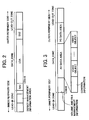
- the recording area is divided into three areas, that is, a lead-in zone, a data zone, and a lead-out zone, from the inner periphery towards the outer periphery of the optical disk.
- the lead-in zone includes a defect management information area in which defect management information is recorded.
- Data is recorded on and reproduced from the data zone.
- An absolute address as a physical address is allocated to each sector of the data zone.
- the data zone is divided into a first spare area (SA1), a user data area (UDA), and a second spare area (SA2).
- SA1 and SA2 each correspond to replacement areas for defective areas of the UDA.
- FIG. 3 shows another example of a disk layout of a recording area of an optical disk in which both AV data and PC data are recorded.
- the recording area is divided into three areas, that is, a lead-in zone, a data zone, and a lead-out zone, from the inner periphery towards the outer periphery of the optical disk.
- the data zone is divided into three areas: (1) a volume and file management information area in which file management information is stored; (2) an AV data area in which AV data is stored; and (3) a PC data area in which data other than AV data is stored.
- the AV data area includes an area in which control information with respect to video object is stored, and an area in which video object is stored.
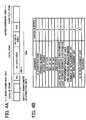
- FIG. 4A shows a disk layout of a recording area of the optical disk 15 according to an embodiment of the present invention.
- the recording area of the optical disk 15 is divided into three areas, that is, a lead-in zone, a data zone, and a lead-out zone, from the inner periphery towards the outer periphery of the optical disk 15.
- the lead-in zone includes a defect management information area, and the data zone includes a SA1, a UDA, and a SA2.
- the UDA is divided into an AV data area and a PC data area.
- file management information with respect to AV data and PC data, and AV data are stored.
- PC data PC data is stored.
- the AV data area is provided at the inner periphery side of the PC data area. The boundary between the AV data area and the PC data area can be arbitrarily set by a user.
- FIG. 4B is a table showing a data structure of defect management information stored in the defect management information area.
- the defect management information includes "ID (identification)”, “Version number”, “Update count”, “Size of UDA”, “Size of SA1”, “Size of SA2”, “Disk status”, “Last written address (LWA) pointer”, “Last verified address (LVA) pointer”, “Replacement disabled area end address (RDAEA) pointer", "Number of replacement list", and "First replacement list” to "N-th replacement list”.
- the identification information which indicates that information is defect management information is stored.
- the version number of defect management information is stored.
- the version number of defect management information is stored.
- the “Update count” the count of update (record) of defect management information is stored.
- the Size of UDA the size of UDA is stored.
- the Size of SA1 the size of SA1 is stored.
- the size of SA2 is stored.
- the disk status information with respect to the condition of a background formatting process such as formatting status, and verification status, is stored. Specifically, in the formatting status, information whether the recording of dummy data (it is called a "de-ice process”) is completed is stored. In the verification status, information whether a verification process is in execution is stored. These information is referred to when the background formatting process is resumed.
- LWA last written address
- LWA pointer pointer information indicating a last address in dummy data recorded in the background formatting process is stored.
- the LWA pointer is referred to when the de-ice process is resumed, and the de-ice process resumes from the address that follows the address pointed by the LWA pointer.
- LVA Layered verified address
- pointer information indicating an address where a last verification process is completed in the background formatting process is stored.
- the LVA pointer is referred to when the verification process is resumed, and the verification process resumes from the address that follows the address pointed by the LVA pointer.
- pointer information indicating a last address of an area in the UDA where defect detection is not performed is stored in the "Replacement disabled area end address (RDAEA) pointer". Specifically, defect management is not performed in an area ranging from the start address of the UDA to an address pointed by the RDAEA pointer. If the RDAEA pointer is 0, defect management is performed in an entire area of the UDA.
- the RDAEA pointer can be arbitrarily set by a user.
- the number of replacement list stored in a replacement list table is stored.
- N number of replacement lists exist.
- a correspondence of an address of a defective block to an address of a replacement block is stored.
- the above-described defect management information stored in a defect management information area of the optical disk is read out and duplicated, and the duplicated defect management information is stored in a RAM of the optical disk apparatus.
- the defect management information stored in the RAM is referred to and updated in a defect management process.
- the updated defect management information in the RAM is written in the defect management information area of the optical disk.
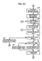
- FIGS. 5A through 5D are flowcharts of process operation steps of the CPU 40 according to an embodiment of the present invention.
- a process operation of the optical disk apparatus 20 will be described referring to FIGS. 5A through 5D.
- This process operation is performed upon receiving a formatting command requesting formatting of a blank optical disk from the host apparatus 90.
- the process operation steps shown in these flowcharts correspond to a sequence of process algorithms of a process program executed by the CPU 40.
- a leading address of a process program corresponding to the flowcharts of FIGS. 5A through 5D is set to a program counter of the CPU 40, and the process operation starts.
- the optical disk 15 is a blank disk.
- an ejection request and a formatting termination request are not issued during the process, and all the user data can be stored in the buffer RAM 34.
- step S401 of FIG. 5A the CPU 40 obtains information with respect to the Replacement disabled area end address (RDAEA) set by a user through the host apparatus 90.
- RAEA Replacement disabled area end address
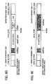
- the boundary between the AV data area and the PC data area has been set by a user as the information with respect to the RDAEA. Therefore, as shown in FIG. 6A, the last address of the AV data area becomes RDAEA, and the AV data area becomes an area (specific area) in which a defect detection process for detecting a defective area is not performed.
- step S403 the CPU 40 sets a pointer indicating the RDAEA obtained in step S401 to the RDAEA pointer (FIG. 4B) in the defect management information, and initializes the defect management information.
- the initialized defect management information is stored in a predetermined area reserved in the RAM 41.
- step S405 the CPU 40 records predetermined information in an initial area (not shown) including the defect management information area in the lead-in zone (this is called an initialization process). At this time, the CPU 40 records the initialized defect management information on the optical disk 15.
- step S407 the CPU 40 notifies the host apparatus 90 of the completion of the initialization process. Then, the CPU 40 sets each of a recording request flag and a reproduction request flag to 0 (zero). After the completion of the initialization process, reception of a recording request and a reproduction request is allowed.
- communications with the host apparatus 90 that is, transmission and reception of data to/from the host apparatus 90 are achieved by interruption processes.
- the recording request flag is set to "1" by an interruption process.
- the reproducing request flag is set to "1" by an interruption process.
- step S409 the CPU 40 refers to the "Disk status" and determines whether a background formatting process is completed in step S409. Because a background formatting process is not completed, the answer in step S409 becomes NO. Then, the CPU 40 determines whether a recording request command or a reproduction request command has been received from the host apparatus 90 by referring to the recording request flag and the reproduction request flag in step S411. If each of the recording request flag and the reproduction request flag is set to "0", the answer in step S411 becomes NO, and the process operation proceeds to step S413.
- step S413 the CPU 40 determines whether a de-ice process is completed by referring to a formatting status included in the "Disk status". Because the de-ice process has not yet been performed, the answer in step S413 becomes NO, and the process operation proceeds to step S415.
- step S415 the CPU 40 determines whether the de-ice process is in execution. Because the de-ice process has not yet been started, the answer in step S415 becomes NO. Then, the CPU 40 obtains a Last written address (LWA) in step S417.
- LWA Last written address
- step S419 the de-ice process is started from an address that follows the LWA obtained in step S417. As shown in FIG. 6B, for example, the de-ice process is started from the leading address of the data zone. Then, the process operation returns to step S409.
- step S415 If the de-ice process is in execution in step S415 (i.e., the answer is YES in step S415), the process operation returns to step S409.
- step S411 and the answer in step S413 become YES
- the de-ice process is continued.
- the de-ice process is skipped in an area in which data is already recorded.
- information with respect to the completion of the de-ice process is set in the formatting status by an interruption process, for example.
- step S413 When the de-ice process is completed in step S413 (i.e., the answer is YES in step S413), the CPU 40 determines whether a verification process is in execution in step S421 in FIG. 5B. Because the verification process has not yet been started, the answer in step S421 becomes NO.
- step S423 the CPU 40 obtains a Last verified address (LVA), and sets an address that follows the obtained LVA as a start address for starting the verification process (hereafter referred to as a "verification start address").
- LVA Last verified address
- the leading address of the SA1 is set as the verification start address, and the verification process is started from the leading address of the SA1.
- step S425 the CPU 40 determines whether an area to be subjected to the verification process is the SA1. Because the verification start address is the leading address of the SA1, the answer in step S425 becomes YES, and the process operation proceeds to step S427.
- step S427 the CPU 40 restricts the area to be subjected to the verification process (verification process execution area) to the SA1. That is, the last address of the SA1 is set as an end address of the verification process (hereafter referred to as a "verification end address").
- the CPU 40 starts the verification process in step S429.
- step S431 the CPU 40 determines whether defect is detected based on the result of the verification process. If defect is not detected in step S431 (i.e., the answer is NO in step S431), the process operation returns to step S409. If defect is detected in step S431 (i.e., the answer is YES in step S431), the process operation proceeds to step S433.
- step S433 the CPU 40 adds information with respect to the defect detected in step S431 to the replacement list (FIG. 4B), and updates the defect management information. Then, the process operation returns to step S409.
- step S411 Until the recording request command or the reproduction request command has been received from the host apparatus 90 in step S411 (i.e., the answer becomes YES in step S411), the verification process for the SA1 is continued. During the execution of the verification process, the answer in step S421 becomes YES, and the process operation proceeds to step S431. When the verification process for the SA1 is completed, the answer in step S425 becomes NO, and the process operation proceeds to S435.
- step S435 the CPU 40 determines whether the address where the last verification process is completed coincides with the start address of the user data area (UDA). As it is immediately after the verification process for the SA1 has been completed, the answer in step S435 becomes YES, and the process operation proceeds to S437.
- step S437 the CPU 40 refers to the RDAEA pointer, and changes the verification start address to an address that follows the address indicated by the RDAEA pointer. As shown in FIG. 6D, for example, the leading address of the PC data area becomes the verification start address. Thereby, the verification process for the AV data area is skipped. It is set that the verification end address becomes the last address of the data zone, that is, the last address of the SA2. Then, the process operation proceeds to step S429.
- step S409 or step S411 becomes YES
- the verification process is continued.
- step S435 becomes NO
- the process operation proceeds to step S429.
- FIG. 6E for example, when the verification process is completed at the last address of the SA2, information with respect to the completion of the background formatting process is set in the "Disk status" by an interruption process.
- step S411 If at least one of the recording request flag and the reproduction request flag is set to "1" in step S411, the answer becomes YES in step S411, and the process operation proceeds to step S439 in FIG. 5C.
- step S439 the background formatting process is interrupted.
- step S441 the CPU 40 updates the content of the defect management information. For example, if the de-ice process is in execution, the pointer indicating the last address of an area in which the de-ice process has been completed is stored in the "LWA pointer". If the verification process is in execution, the pointer indicating the last address of an area in which the verification process has been completed is stored in the "LVA pointer".
- step S443 the CPU 40 determines whether a recording request command has been received from the host apparatus 90 by referring to the recording request flag. If the recording request flag is set to "1", the answer becomes YES in step S443, and the process operation proceeds to step S445. It is assumed that user data is transmitted from the host apparatus 90 following the recording request command, and is stored in the buffer RAM 34 as data to be recorded.
- step S445 the CPU 40 sets the first block data of the data to be recorded as writing data. Then, the CPU 40 obtains an area (hereafter may be referred to as a "designated area") where the writing data is to be recorded based on a recording start address included in the recording request command in step S447.
- the designated area means a recording target area.
- step S449 the CPU 40 determines whether the designated area is included in a defect management area in which defect management is performed by referring to the RDAEA pointer. Specifically, the CPU 40 compares the address of the designated area with an address indicated by the RDAEA pointer. If the address of the designated area is greater than the address indicated by the RDAEA pointer, the answer becomes YES in step S449, and the process operation proceeds to step S451.
- step S451 the CPU 40 determines whether the designated area is a defective area by referring to the replacement list. If the answer is NO in step S451, the process operation proceeds to step S455.
- step S455 the writing data is recorded in the designated area. As shown in FIG. 7A, for example, the writing data (user data) is recorded in the PC data area.
- step S459 the verification process is performed on the designated area in which the writing data is recorded.
- step S461 in FIG. 5D the CPU 40 determines whether defect is detected in the designated area based on the result of the verification process. If defect is detected in step S461 (i.e., the answer is YES in step S461), the writing data is recorded in a predetermined replacement area in step S463.
- step S465 the defect management information is updated. That is, information with respect to the detected defect is added to the replacement list. Then, the CPU 40 determines whether all the user data is recorded in step S467. If there is non-recorded user data, the answer becomes NO in step S467, and the process operation proceeds to step S469.
- step S469 the CPU 40 sets next block data of the data to be recorded as writing data, and the process operation returns to step S447.
- step S461 If defect is not detected in step S461 (i.e., the answer is NO in step S461), the process operation proceeds to step S467.
- step S453 the CPU 40 causes the writing data to be recorded in a designated replacement area by referring to the replacement list. Then, the process operation proceeds to step S459.
- step S457 the writing data is recorded in the designated area. As shown in FIG. 7B, for example, the writing data (user data) is recorded in the AV data area. Then, the process operation proceeds to step S467. That is, the verification process is not performed.
- step S467 Until the answer in step S467 becomes YES, the loop process of steps S447 through S469 is repeated.
- step S467 When all the user data is recorded (i.e., the answer is YES in step S467), the CPU 40 resets the recording request flag to "0", and the process operation proceeds to step S487.
- step S487 the CPU 40 resumes the background formatting process by referring to the "Disk status". Then, the process operation returns to step S409.
- step S443 If the recording request flag is set to "0" in step S443, the answer becomes NO in step S443, and the CPU 40 obtains an area (hereafter may be referred to as a "reproduction requested area") from which a user requests to reproduce the user data based on a reproduction start address and a reproduction data length included in the reproduction request command in step S471.
- a reproduction requested area an area (hereafter may be referred to as a "reproduction requested area") from which a user requests to reproduce the user data based on a reproduction start address and a reproduction data length included in the reproduction request command in step S471.
- step S473 the CPU 40 sets the first reproduction block in the reproduction requested area as an area (hereafter referred to as a "reproduction target area") from which the user data is reproduced.
- step S475 the CPU 40 determines whether the reproduction target area is included in the defect management area by referring to the RDAEA pointer. Specifically, the CPU 40 compares the address of the reproduction target area with an address indicated by the RDAEA pointer. If the address of the reproduction target area is greater than the address indicated by the RDAEA pointer, the answer becomes YES in step S475, and the process operation proceeds to step S477.
- step S477 the CPU 40 determines whether the reproduction target area is a defective area by referring to the replacement list. If the answer is NO in step S477, the process operation proceeds to step S481. In step S481, the user data is reproduced from the reproduction target area.
- step S483 the CPU 40 determines whether the user data is reproduced from all the reproduction requested area in step S483. If there is a non-reproduced reproduction requested area, the answer becomes NO in step S483, and the process operation proceeds to step S485.
- step S485 the CPU 40 sets a next reproduction block in the reproduction requested area as a reproduction target area, and the process operation returns to step S475.
- step S477 If the reproduction target area is a defective area in step S477, the answer in step S477 becomes YES, and the process operation proceeds to step S479.
- step S479 the CPU 40 causes the user data to be reproduced from a designated replacement area by referring to the replacement list. Then, the process operation proceeds to step S483.
- step S475 if the reproduction target area is not included in the defect management area in step S475, the answer becomes NO in step S475, and the process operation proceeds to step S481.
- step S483 Until the answer in step S483 becomes YES, the loop process of steps S475 through S485 is repeated.
- the CPU 40 resets the reproduction request flag to "0", and the process operation proceeds to step S487.
- the background formatting process is performed during a period when the recording request command and the reproduction request command are not received from the host apparatus 90. If the background formatting process is completed in step S409 (i.e., the answer is YES in step S409), a predetermined end process is performed, and the process operation executed in response to receiving the formatting command is ended, that is, the formatting of the optical disk 15 is completed. If the replacement list is updated, the updated replacement list is recorded on the optical disk 15 in this end process.
- the optical disk apparatus 20 of the present embodiment provides a setting mechanism, a determining mechanism, and a replacement mechanism.
- the setting mechanism is achieved by executing process operation step S403 in FIG. 5A
- the determining mechanism is achieved by executing process operation steps S423 through S427 and S435 and S437 in FIG. 5B, and S449 in FIG. 5C.
- the replacement mechanism is achieved by executing process operation steps S459 through S463 in FIGS. 5C and 5D.
- a recording mechanism is provided by employing the optical pickup unit 23, the laser control circuit 24, the encoder 25, and the CPU 40 and by executing the program with the CPU 40.
- the pointer indicating information with respect to a specific area that is, the replacement disabled area end address (RDAEA)
- the RDAEA pointer in the defect management information is set to the RDAEA pointer in the defect management information, and the defect management information is initialized.
- the AV data area becomes a specific area in which a defect detection process need not be performed. Because defect management is not performed in the AV data area, information can be consecutively recorded in the AV data area, so that the continuity of AV data can be achieved.
- defect management is performed in the PC data area, the reliability of data recorded in the PC data area can be ensured. Thus, plural types of data for different uses can be properly recorded on the same information recording medium.
- the RDAEA pointer is stored in the optical disk 15, even if the optical disk 15 is used in a different optical disk apparatus, the continuity of data recorded in the AV data area can be achieved, and the reliability of data recorded in the PC data area can be ensured.
- the convenience of user is enhanced.
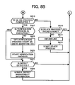
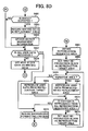
- FIGS. 8A through 8D a process operation according to another embodiment will be described referring to FIGS. 8A through 8D.
- a method of setting information with respect to a specific area in which a verification process need not be performed is different from the process operation of the above-described embodiment. Therefore, a part of a program stored in the flash memory 39 and executed in this embodiment is different from the program executed in the above-described embodiment.
- the configuration of the optical disk apparatus of this embodiment is similar to that of the optical disk apparatus 20 shown in FIG. 1. Further, the disk layout of the recording area of the optical disk 15 used in this embodiment is the same as that of the optical disk 15 used in the above-described embodiment. Because the RDAEA information is not used in this embodiment, the "Replacement disabled area end address (RDAEA) pointer" in the data structure of defect management information shown in FIG. 4B may be replaced with "Reserved".
- RDAEA Replacement disabled area end address
- FIGS. 8A through 8D The process operation executed in response to receiving a formatting command requesting formatting of a blank optical disk from the host apparatus 90 by the optical disk apparatus 20 will be described referring to FIGS. 8A through 8D.
- the preconditions are similar to those in the above-described embodiment.
- the process operation steps shown in these flowcharts correspond to a sequence of process algorithms of a process program executed by the CPU 40.
- a leading address of a process program corresponding to the flowcharts of FIGS. 8A through 8D is set to a program counter of the CPU 40, and the process operation starts.
- step S601 of FIG. 8A the CPU 40 obtains information with respect to the Last verified address (LVA) set by a user through the host apparatus 90.
- LVA Last verified address
- the boundary between the AV data area and the PC data area has been set by a user as the information with respect to the LVA. Therefore, as shown in FIG. 9A, the last address of the AV data area is obtained as the LVA.
- step S603 the CPU 40 sets a pointer indicating the LVA obtained in step S601 to the LVA pointer (FIG. 4B) in the defect management information, and initializes the defect management information.
- the initialized defect management information is stored in a predetermined area reserved in the RAM 41. As shown in FIG. 9A, the last address of the AV data area is set as the LVA. Therefore, the defect detection process for the SA1 and the AV data area is regarded as having been already completed.
- the CPU 40 refers to the "Disk status" and determines whether a background formatting process is completed in step S609. Because a background formatting process is not completed, the answer in step S609 becomes NO. Then, the CPU 40 determines whether a recording request command or a reproduction request command has been received from the host apparatus 90 by referring to the recording request flag and the reproduction request flag in step S611. If each of the recording request flag and the reproduction request flag is set to "0", the answer in step S611 becomes NO, and the process operation proceeds to step S613 in FIG. 8B.
- step S613 the CPU 40 determines whether a de-ice process is completed by referring to a formatting status included in the "Disk status". Because the de-ice process has not yet been performed, the answer in step S613 becomes NO, and the process operation proceeds to step S615.
- step S615 the CPU 40 determines whether the de-ice process is in execution. Because the de-ice process has not yet been started, the answer in step S615 becomes NO. Then, the CPU 40 obtains a Last Written address (LWA) in step S617.
- LWA Last Written address
- steps S617 and S619 the process operation similar to steps S417 and S419 is performed. Then, the process operation returns to step S609.
- step S615 If the de-ice process is in execution in step S615 (i.e., the answer is YES in step S615), the process operation returns to step S609. Until the answer in step S611 and the answer in step S613 become YES, the de-ice process is continued.
- step S613 When the de-ice process is completed in step S613 (i.e., the answer is YES in step S613), the CPU 40 determines whether a verification process is in execution in step S621. Because the verification process has not yet been started, the answer in step S621 becomes NO.
- step S623 the CPU 40 obtains a Last verified address (LVA), and sets an address that follows the obtained LVA as a verification start address.
- LVA Last verified address
- FIG.9B for example, the verification process is started from the leading address of the PC data area. Accordingly, the verification process is not performed in the SA1 and the AV data area.
- step S627 the CPU 40 determines whether defect is detected based on the result of the verification process. If defect is not detected in step S627 (i.e., the answer is NO in step S627), the process operation returns to step S609. If defect is detected in step S627 (i.e., the answer is YES in step S627), the process operation proceeds to step S629.
- step S629 the CPU 40 adds the information with respect to the defect detected in step S627 to the replacement list (FIG. 4B), and updates the defect management information. Then, the process operation returns to step S609. During the execution of the verification process, the answer in step S621 becomes YES, and the process operation proceeds to step S627.
- step S609 or step S611 Until the answer in step S609 or step S611 becomes YES, each verification process in the PC data area and the SA2 is continued.
- step S611 If at least one of the recording request flag and the reproduction request flag is set to "1" in step S611, the answer becomes YES in step S611, and the process operation proceeds to step S631 in FIG. 8C.
- steps S631 and S633 the process operation similar to steps S439 and S441 in FIG. 5C is performed.
- step S635 the CPU 40 determines whether a recording request command has been received from the host apparatus 90 by referring to the recording request flag. If the recording request flag is set to "1", the answer becomes YES in step S635, and the process operation proceeds to step S637.
- steps S637 and S639 the process operation similar to steps S445 and S447 in FIG. 5C is performed.
- step S641 the CPU 40 determines whether the designated area is a defective area by referring to the replacement list. If the answer is NO in step S641, the process operation proceeds to step S645.
- step S645 the writing data is recorded in the designated area. As shown in FIGS. 9C and 9D, for example, the writing data (user data) is recorded in the PC data area (FIG. 9C) and the AV data area (FIG. 9D).
- step S647 the CPU 40 determines whether the designated area is included in an area in which a verification process has not yet been performed by referring to the LVA pointer. Specifically, the CPU 40 compares the address of the designated area with an address indicated by the LVA pointer. If the address of the designated area is greater than the address indicated by the LVA pointer, the answer becomes YES in step S647, and the process operation proceeds to step S649.
- step S649 the verification process is performed on the designated area in which the writing data is recorded. Then, in step S651 in FIG. 8D, the CPU 40 determines whether defect is detected in the designated area based on the result of the verification process. If defect is detected in step S651 (i.e., the answer is YES in step S651), the process operation proceeds to step S653.
- steps S653 and S655 the process operation similar to steps S463 and S465 in FIG. 5D is performed.
- step S657 the CPU 40 determines whether all the user data is recorded in step S657. If there is non-recorded user data, the answer becomes NO in step S657, and the process operation proceeds to step S659.
- step S659 the CPU 40 sets next block data of the data to be recorded as writing data, and the process operation returns to step S639.
- step S651 If defect is not detected in step S651 (i.e., the answer is NO in step S651), the process operation proceeds to step S657.
- step S647 the answer becomes NO in step S647, and the process operation proceeds to step S657. That is, the verification process is not performed in the designated area.
- step S643 the CPU 40 causes the writing data to be recorded in a designated replacement area by referring to the replacement list. Then, the process operation proceeds to step S649.
- step S657 Until the answer in step S657 becomes YES, the loop process of steps S639 through S659 is repeated.
- the CPU 40 resets the recording request flag to "0", and the process operation proceeds to step S675.
- step S675 the CPU 40 resumes the background formatting process by referring to the "Disk status”. Then, the process operation returns to step S609.
- step S635 If the recording request flag is set to "0" in step S635, the answer becomes NO in step S635, and the process operation proceeds to step S661.
- steps S661 and S663 the process operation similar to steps S471 and S473 in FIG. 5D is performed.
- step S665 the CPU 40 determines whether the reproduction target area is a defective area by referring to the replacement list. If the answer is NO in step S665, the process operation proceeds to step S669. In step S669, the user data is reproduced from a reproduction target area.
- step S671 the CPU 40 determines whether the user data is reproduced from all the reproduction requested area in step S671. If there is a non-reproduced reproduction requested area, the answer becomes NO in step S671, and the process operation proceeds to step S673.
- step S673 the CPU 40 sets a next reproduction block in the reproduction requested area as a reproduction target area, and the process operation returns to step S665. If the reproduction target area is a defective area in step S665, the answer in step S665 becomes YES, and the process operation proceeds to step S667. In step S667, the CPU 40 causes the user data to be reproduced from a designated replacement area by referring to the replacement list. Then, the process operation proceeds to step S671.
- step S671 Until the answer in step S671 becomes YES, the loop process of steps S665 through S673 is repeated.
- the CPU 40 resets the reproduction request flag to "0", and the process operation proceeds to step S675.
- the background formatting process is performed during a period when the recording request command and the reproduction request command are not received from the host apparatus 90. If the background formatting process is completed in step S609 (i.e., the answer is YES in step S609), a predetermined end process is performed, and the process operation executed in response to receiving the formatting command is ended, that is, the formatting of the optical disk 15 is completed. If the replacement list is updated, the updated replacement list is recorded on the optical disk 15 in this end process.
- the optical disk apparatus 20 of the present embodiment provides a setting mechanism, a determining mechanism, and a replacement mechanism.
- the setting mechanism is achieved by executing process operation step S603 in FIG. 8A
- the determining mechanism is achieved by executing process operation step S623 in FIG. 8B, and S647 in FIG. 8C.
- the replacement mechanism is achieved by executing process operation steps S649 through S653 in FIGS. 8C and 8D.
- a recording mechanism is provided by employing the optical pickup unit 23, the laser control circuit 24, the encoder 25, and the CPU 40 and by executing the program with the CPU 40.
- the last address of the AV data area is set to the last verified address (LVA) as dummy information indicating that the execution of the verification process in the SA1 and the AV data area has been already completed. Therefore, the AV data area is regarded as not including a defective area, so that defect management is not performed in the AV data area. Thereby, information can be consecutively recorded in the AV data area, so that the continuity of AV data can be achieved. In contrast, because defect management is performed in the PC data area, the reliability of data recorded in the PC data area can be ensured. Thus, plural types of data for different uses can be properly recorded on the same information recording medium.
- the LVA pointer is stored in the optical disk 15, even if the optical disk 15 is used in a different optical disk apparatus, the continuity of data recorded in the AV data area can be achieved, and the reliability of data recorded in the PC data area can be ensured.
- the convenience of user is enhanced.
- the computer program is stored in the flash memory 39.
- the computer program may be stored in other recording media such as a compact disk (CD), an optical magnetic disk, a digital versatile disk (DVD), a memory card, a universal serial bus (USB) memory, and a flexible disk.
- the computer program may be loaded to the flash memory 39 via a reproduction device or an interface which corresponds to each of the recording media.
- the computer program may be transferred to the flash memory 39 via a network such as a local-area network (LAN), an intranet, and the Internet. Any other method may be employed so long as the computer program can be loaded to the flash memory 39.
- the optical disk 15 has been described as a DVD in the above embodiments, the optical disk 15 is not necessarily a DVD, but may be a CD or a next-generation information recording medium made for a laser light beam with a wavelength of about 405 nm.
- the optical pickup unit 23 of the present embodiments includes a single semiconductor laser, plural semiconductor lasers that emit laser light beams with different wavelengths may also be employed.
- the plural semiconductor lasers may include at least one of a semiconductor laser that emits a laser light beam with a wavelength of about 405 nm, a semiconductor laser that emits a laser light beam with a wavelength of about 660 nm, and a semiconductor laser that emits a laser light beam with a wavelength of about 780 nm. That is, the optical disk apparatus 20 may be adapted to plural kinds of optical disks each conforming to the standards different with one another.
Landscapes
- Engineering & Computer Science (AREA)
- Signal Processing (AREA)
- Signal Processing For Digital Recording And Reproducing (AREA)
- Optical Recording Or Reproduction (AREA)
Applications Claiming Priority (4)
| Application Number | Priority Date | Filing Date | Title |
|---|---|---|---|
| JP2004017748 | 2004-01-27 | ||
| JP2004017748 | 2004-01-27 | ||
| JP2004112644A JP4223431B2 (ja) | 2004-01-27 | 2004-04-07 | 欠陥管理情報設定方法、記録方法及び情報記録装置 |
| JP2004112644 | 2004-04-07 |
Publications (1)
| Publication Number | Publication Date |
|---|---|
| EP1564741A1 true EP1564741A1 (de) | 2005-08-17 |
Family
ID=34703352
Family Applications (1)
| Application Number | Title | Priority Date | Filing Date |
|---|---|---|---|
| EP05250420A Ceased EP1564741A1 (de) | 2004-01-27 | 2005-01-27 | Methode Defektmanagementinformationen zu setzen, Datenaufnahmemethode, Computerprogramm, computer-lesbares Aufzeichnungsmedium und Informationsaufzeichnungsgerät, das mehrere Datenarten für unterschiedliche Nutzungsarten richtig auf dem gleichen Informationsaufzeichnungsgerät aufnimmt |
Country Status (4)
| Country | Link |
|---|---|
| US (1) | US7663989B2 (de) |
| EP (1) | EP1564741A1 (de) |
| JP (1) | JP4223431B2 (de) |
| CN (1) | CN100429713C (de) |
Cited By (2)
| Publication number | Priority date | Publication date | Assignee | Title |
|---|---|---|---|---|
| EP1796092A3 (de) * | 2005-12-08 | 2009-04-01 | NEC Corporation | Aufzeichnungsvorrichtung für optische Platten und optisches Plattenmedium |
| US8407415B2 (en) | 2005-12-06 | 2013-03-26 | Koninklijke Philips Electronics N.V. | De-icing of multi-layer storage media |
Families Citing this family (6)
| Publication number | Priority date | Publication date | Assignee | Title |
|---|---|---|---|---|
| EP1679710B1 (de) * | 2005-01-10 | 2013-08-14 | Nero Ag | Fehlerverwaltung verwendentes Verfahren zum Schreiben von Datenblöken auf einem blök-adressierbaren Speichermedium |
| US20060168499A1 (en) * | 2005-01-27 | 2006-07-27 | Edwards Jathan D | Data archive verify software |
| JP2007323695A (ja) * | 2006-05-30 | 2007-12-13 | Nec Corp | 書き換え型光ディスクの記録制御方法およびその記録再生用のドライブ装置 |
| KR20100121806A (ko) * | 2009-05-11 | 2010-11-19 | 엘지전자 주식회사 | 기록매체, 데이터 기록/재생 방법 및 데이터 기록/재생 장치 |
| CN105472831B (zh) * | 2014-09-05 | 2018-06-29 | 深圳光启智能光子技术有限公司 | 一种光驱动芯片控制发光器件的方法及其光驱动芯片 |
| CN116661698B (zh) * | 2023-06-16 | 2024-02-13 | 浙江清环智慧科技有限公司 | 一种窨井排水监测设备中存储器的管理方法及装置 |
Citations (5)
| Publication number | Priority date | Publication date | Assignee | Title |
|---|---|---|---|---|
| EP0952573A2 (de) * | 1998-04-20 | 1999-10-27 | Samsung Electronics Co., Ltd. | Aufzeichnungsmedium zur Speicherung von Fehlermanagementinformationen zur Aufzeichnung von Echtzeitdaten, Verfahren für das Fehlermanagement dazu, und Verfahren zur Aufzeichnung von Echtzeitdaten |
| EP1100087A2 (de) * | 1999-11-09 | 2001-05-16 | Kabushiki Kaisha Toshiba | Informationsaufzeichnungsmedium mit Informationen für Datenintegrität |
| EP1253590A2 (de) * | 2001-04-25 | 2002-10-30 | Ricoh Company, Ltd. | Datenspeichergerät,das entweder ein Aufzeichnungsmedium im Hintergrund zertifiziert oder die auf das Aufzeichnungsmedium geschriebenen Daten verifiziert |
| US20030135800A1 (en) * | 1998-03-02 | 2003-07-17 | Lg Electronics Inc. | Method for creating defect management information in an recording medium, and apparatus and medium based on said method |
| US6621782B1 (en) * | 1998-08-05 | 2003-09-16 | Mitsubishi Denki Kabushiki Kaisha | Optical disk, an optical disk device, and a method of managing defects in an optical disk |
Family Cites Families (21)
| Publication number | Priority date | Publication date | Assignee | Title |
|---|---|---|---|---|
| JPH0428061A (ja) * | 1990-05-24 | 1992-01-30 | Matsushita Electric Ind Co Ltd | 情報記録媒体と情報記録再生装置 |
| US6370325B2 (en) * | 1997-09-17 | 2002-04-09 | Matsushita Electric Industrial Co., Ltd. | Optical disc recording apparatus, computer-readable recording medium recording a file management program, and optical disc |
| JP3383587B2 (ja) | 1998-07-07 | 2003-03-04 | 株式会社東芝 | 静止画像連続情報記録方法と光ディスクと光ディスクの情報再生装置と情報再生方法 |
| JP3733752B2 (ja) | 1998-07-24 | 2006-01-11 | 三菱電機株式会社 | 光ディスクの欠陥管理方法、光ディスク、光ディスク装置、及び、再生方法 |
| WO2000051114A1 (en) * | 1999-02-26 | 2000-08-31 | Matsushita Electric Industrial Co., Ltd. | Optical information recording/reproducing device |
| JP4344485B2 (ja) | 2000-03-08 | 2009-10-14 | パナソニック株式会社 | 情報記録媒体、情報記録方法および情報再生方法 |
| US7072256B2 (en) | 2000-03-08 | 2006-07-04 | Matsushita Electric Industrial Co., Ltd. | Information recording medium, information recording method and information reproduction method |
| JP3860394B2 (ja) | 2000-06-20 | 2006-12-20 | 株式会社リコー | 情報再生方法及び情報再生装置 |
| JP4006184B2 (ja) | 2001-01-30 | 2007-11-14 | 株式会社リコー | 情報記録再生方法、情報記録再生装置、情報処理装置及びコンピュータ・プログラム |
| SG106612A1 (en) * | 2001-05-29 | 2004-10-29 | Sony Electronics Singapore Pte | A force sensing device |
| JP3878442B2 (ja) | 2001-07-30 | 2007-02-07 | 株式会社リコー | 情報記録再生装置とプログラム |
| JP3674565B2 (ja) * | 2001-09-25 | 2005-07-20 | ティアック株式会社 | 光ディスク装置 |
| JP3886800B2 (ja) | 2001-12-19 | 2007-02-28 | 株式会社リコー | データ管理情報取得方法、情報再生装置、並びにデータ管理情報取得プログラム及び記録媒体 |
| JP4100913B2 (ja) | 2002-01-15 | 2008-06-11 | 株式会社リコー | 情報再生装置、データ管理情報取得方法、データ管理情報取得プログラム、記憶媒体、及び再生システム |
| JP2004005842A (ja) | 2002-05-31 | 2004-01-08 | Ricoh Co Ltd | 記録方法、記録媒体、プログラム及び情報記録媒体、並びに情報記録装置 |
| JP4279515B2 (ja) * | 2002-06-25 | 2009-06-17 | 株式会社日立グローバルストレージテクノロジーズ | 記録再生装置 |
| JP4183553B2 (ja) | 2002-09-19 | 2008-11-19 | 株式会社リコー | 記録方法、プログラム及び記録媒体、並びに情報記録装置 |
| JP4270991B2 (ja) | 2002-10-11 | 2009-06-03 | 株式会社リコー | 情報記録装置、情報記録方法、情報記録用プログラム、情報記録用プログラムを記憶する記憶媒体、及び情報記録システム |
| JP3867038B2 (ja) | 2002-10-23 | 2007-01-10 | 株式会社リコー | 情報記録装置と情報記録方法とプログラムと記録媒体 |
| JP4082670B2 (ja) | 2003-01-23 | 2008-04-30 | 株式会社リコー | 記録方法及び情報記録装置 |
| JP3856449B2 (ja) | 2003-04-24 | 2006-12-13 | 株式会社リコー | 再生方法、プログラム及び記録媒体、並びにドライブ装置 |
-
2004
- 2004-04-07 JP JP2004112644A patent/JP4223431B2/ja not_active Expired - Fee Related
-
2005
- 2005-01-26 US US11/042,210 patent/US7663989B2/en not_active Expired - Fee Related
- 2005-01-27 EP EP05250420A patent/EP1564741A1/de not_active Ceased
- 2005-01-27 CN CNB2005100058446A patent/CN100429713C/zh not_active Expired - Fee Related
Patent Citations (5)
| Publication number | Priority date | Publication date | Assignee | Title |
|---|---|---|---|---|
| US20030135800A1 (en) * | 1998-03-02 | 2003-07-17 | Lg Electronics Inc. | Method for creating defect management information in an recording medium, and apparatus and medium based on said method |
| EP0952573A2 (de) * | 1998-04-20 | 1999-10-27 | Samsung Electronics Co., Ltd. | Aufzeichnungsmedium zur Speicherung von Fehlermanagementinformationen zur Aufzeichnung von Echtzeitdaten, Verfahren für das Fehlermanagement dazu, und Verfahren zur Aufzeichnung von Echtzeitdaten |
| US6621782B1 (en) * | 1998-08-05 | 2003-09-16 | Mitsubishi Denki Kabushiki Kaisha | Optical disk, an optical disk device, and a method of managing defects in an optical disk |
| EP1100087A2 (de) * | 1999-11-09 | 2001-05-16 | Kabushiki Kaisha Toshiba | Informationsaufzeichnungsmedium mit Informationen für Datenintegrität |
| EP1253590A2 (de) * | 2001-04-25 | 2002-10-30 | Ricoh Company, Ltd. | Datenspeichergerät,das entweder ein Aufzeichnungsmedium im Hintergrund zertifiziert oder die auf das Aufzeichnungsmedium geschriebenen Daten verifiziert |
Cited By (2)
| Publication number | Priority date | Publication date | Assignee | Title |
|---|---|---|---|---|
| US8407415B2 (en) | 2005-12-06 | 2013-03-26 | Koninklijke Philips Electronics N.V. | De-icing of multi-layer storage media |
| EP1796092A3 (de) * | 2005-12-08 | 2009-04-01 | NEC Corporation | Aufzeichnungsvorrichtung für optische Platten und optisches Plattenmedium |
Also Published As
| Publication number | Publication date |
|---|---|
| US7663989B2 (en) | 2010-02-16 |
| JP4223431B2 (ja) | 2009-02-12 |
| CN100429713C (zh) | 2008-10-29 |
| JP2005243203A (ja) | 2005-09-08 |
| CN1655271A (zh) | 2005-08-17 |
| US20050163010A1 (en) | 2005-07-28 |
Similar Documents
| Publication | Publication Date | Title |
|---|---|---|
| CN101241747B (zh) | 管理信息的系统 | |
| JP4544642B2 (ja) | 記録方法及び情報記録装置 | |
| US7180841B2 (en) | Recording method, recording medium, program, information recording medium, and information recording device | |
| JP3867038B2 (ja) | 情報記録装置と情報記録方法とプログラムと記録媒体 | |
| JP4183553B2 (ja) | 記録方法、プログラム及び記録媒体、並びに情報記録装置 | |
| JP3796858B2 (ja) | 光ディスク読出装置 | |
| JP4686446B2 (ja) | 光ディスクのフォーマット装置、方法、及びコンピュータプログラム | |
| JP4082670B2 (ja) | 記録方法及び情報記録装置 | |
| EP1564741A1 (de) | Methode Defektmanagementinformationen zu setzen, Datenaufnahmemethode, Computerprogramm, computer-lesbares Aufzeichnungsmedium und Informationsaufzeichnungsgerät, das mehrere Datenarten für unterschiedliche Nutzungsarten richtig auf dem gleichen Informationsaufzeichnungsgerät aufnimmt | |
| CN100385382C (zh) | 用于记录信息的装置和方法 | |
| JP4095977B2 (ja) | 欠陥管理方法及び情報記録装置 | |
| KR100662290B1 (ko) | 광 기록매체 상의 데이터 복사 및 이동 방법 | |
| JP2008507797A (ja) | 記録担体に情報を記録する装置及び方法 | |
| JPH10106170A (ja) | 光ディスク情報記録システム | |
| JP2005327405A (ja) | 記録方法、情報記録装置、情報再生装置、プログラム及び記録媒体 | |
| EP1943644A1 (de) | Informationsaufzeichnungsvorrichtung | |
| KR20070040402A (ko) | 기록 매체 상의 데이터 공간 관리 방법 | |
| JP2005302143A (ja) | 初期化方法、再生方法、プログラム及び記録媒体、データ構造、情報記録装置、並びに情報再生装置 | |
| JP2003173626A (ja) | 情報記録再生装置 | |
| JP3913769B2 (ja) | システム | |
| JP4144893B2 (ja) | システム、データ再生方法及び情報再生装置 | |
| JPH1064066A (ja) | 光ディスク情報記録システム | |
| JP2002208226A (ja) | リンキング損失領域にデータを上書きする方法 | |
| JP2006185559A (ja) | 情報記録再生装置、情報記録再生方法、プログラム、コンピュータ読み取り可能な記録媒体 | |
| JP2008217987A (ja) | 記録方法、プログラム、記録媒体、情報記録装置及び情報記録システム |
Legal Events
| Date | Code | Title | Description |
|---|---|---|---|
| PUAI | Public reference made under article 153(3) epc to a published international application that has entered the european phase |
Free format text: ORIGINAL CODE: 0009012 |
|
| 17P | Request for examination filed |
Effective date: 20050210 |
|
| AK | Designated contracting states |
Kind code of ref document: A1 Designated state(s): AT BE BG CH CY CZ DE DK EE ES FI FR GB GR HU IE IS IT LI LT LU MC NL PL PT RO SE SI SK TR |
|
| AX | Request for extension of the european patent |
Extension state: AL BA HR LV MK YU |
|
| AKX | Designation fees paid |
Designated state(s): DE FR GB |
|
| 17Q | First examination report despatched |
Effective date: 20070208 |
|
| STAA | Information on the status of an ep patent application or granted ep patent |
Free format text: STATUS: THE APPLICATION HAS BEEN REFUSED |
|
| 18R | Application refused |
Effective date: 20121214 |