EP1564689A2 - Method for operating a lock with back-up device for locking and/or unlocking the lock - Google Patents
Method for operating a lock with back-up device for locking and/or unlocking the lock Download PDFInfo
- Publication number
- EP1564689A2 EP1564689A2 EP05000884A EP05000884A EP1564689A2 EP 1564689 A2 EP1564689 A2 EP 1564689A2 EP 05000884 A EP05000884 A EP 05000884A EP 05000884 A EP05000884 A EP 05000884A EP 1564689 A2 EP1564689 A2 EP 1564689A2
- Authority
- EP
- European Patent Office
- Prior art keywords
- transmitter
- vehicle
- energy
- handle
- emergency
- Prior art date
- Legal status (The legal status is an assumption and is not a legal conclusion. Google has not performed a legal analysis and makes no representation as to the accuracy of the status listed.)
- Withdrawn
Links
Images

Classifications
-
- B—PERFORMING OPERATIONS; TRANSPORTING
- B60—VEHICLES IN GENERAL
- B60R—VEHICLES, VEHICLE FITTINGS, OR VEHICLE PARTS, NOT OTHERWISE PROVIDED FOR
- B60R25/00—Fittings or systems for preventing or indicating unauthorised use or theft of vehicles
- B60R25/20—Means to switch the anti-theft system on or off
- B60R25/24—Means to switch the anti-theft system on or off using electronic identifiers containing a code not memorised by the user
- B60R25/246—Means to switch the anti-theft system on or off using electronic identifiers containing a code not memorised by the user characterised by the challenge triggering
-
- B—PERFORMING OPERATIONS; TRANSPORTING
- B60—VEHICLES IN GENERAL
- B60R—VEHICLES, VEHICLE FITTINGS, OR VEHICLE PARTS, NOT OTHERWISE PROVIDED FOR
- B60R25/00—Fittings or systems for preventing or indicating unauthorised use or theft of vehicles
- B60R25/40—Features of the power supply for the anti-theft system, e.g. anti-theft batteries, back-up power supply or means to save battery power
- B60R25/403—Power supply in the vehicle
-
- G—PHYSICS
- G07—CHECKING-DEVICES
- G07C—TIME OR ATTENDANCE REGISTERS; REGISTERING OR INDICATING THE WORKING OF MACHINES; GENERATING RANDOM NUMBERS; VOTING OR LOTTERY APPARATUS; ARRANGEMENTS, SYSTEMS OR APPARATUS FOR CHECKING NOT PROVIDED FOR ELSEWHERE
- G07C9/00—Individual registration on entry or exit
- G07C9/00174—Electronically operated locks; Circuits therefor; Nonmechanical keys therefor, e.g. passive or active electrical keys or other data carriers without mechanical keys
- G07C9/00309—Electronically operated locks; Circuits therefor; Nonmechanical keys therefor, e.g. passive or active electrical keys or other data carriers without mechanical keys operated with bidirectional data transmission between data carrier and locks
-
- G—PHYSICS
- G07—CHECKING-DEVICES
- G07C—TIME OR ATTENDANCE REGISTERS; REGISTERING OR INDICATING THE WORKING OF MACHINES; GENERATING RANDOM NUMBERS; VOTING OR LOTTERY APPARATUS; ARRANGEMENTS, SYSTEMS OR APPARATUS FOR CHECKING NOT PROVIDED FOR ELSEWHERE
- G07C9/00—Individual registration on entry or exit
- G07C9/00174—Electronically operated locks; Circuits therefor; Nonmechanical keys therefor, e.g. passive or active electrical keys or other data carriers without mechanical keys
- G07C2009/00634—Power supply for the lock
Definitions
- the invention is directed to a device that in the preamble of claim 1 specified type.
- a handle On the outside of the door sits a handle, which is in operative connection with the castle stands.
- the lock can be between a secured position where the Handle operation is ineffective, be transferred to an unlocked position, where a handle operation is successful and allows the handle to open the door.
- ID transmitter an identification transmitter
- a communication takes place by means of code signals.
- this ID transmitter is carried by the authorized vehicle user.
- a dormant battery in the vehicle and a portable power source in the ID transmitter required.
- an in-vehicle actuator which for the Reversal between the release and / or securing the lock is used.
- the invention has for its object to provide a reliable device in the To develop preamble of claim 1 mentioned type, the simpler and is designed to save space. This is inventively by the in claim 1 achieved the following special importance.
- the invention proposes, in an emergency, the electrical energy of the power source in the ID transmitter to use for electrical actuation of the actuator. Then in the Emergency, as is normal, by electrical means the lock between his Locking and Entommes ein be reversed. This will be the usual portable ID transmitter an active part of the emergency device according to the invention.
- In the Invention accounts for all mechanical devices and all mechanical Identification means that were required in the known emergency device. Of the Space required in the prior art is saved in the invention. To to a few space-saving electrical components, such as the energy storage in the vehicle, are no additional mechanical emergency actuation means in the invention required.
- the emergency device according to the invention may e.g. in the following way be educated.
- the ID transmitter in a particular special position towards the vehicle and / or at the ID transmitter or vehicle Special operation trigger, so that electrical energy from the power source of the ID transmitter flows in an arranged in the vehicle energy storage. If the Energy storage has achieved a sufficient electrical level, he can be discharged while pressing the actuator in the usual way.
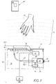
- Fig. 1 In the diagram of Fig. 1 are of the vehicle 10, only a door 11 and a Vehicle battery 12, which is an electrical control unit 13 and via this Control unit 13 an actuator 14 is supplied with electrical energy.
- a handle 20 At the Outside 18 of the door 11, a handle 20 is disposed on a support 21st hinged or hinged articulated.
- the carrier 21 is not closer shown attachment of the whole, finally described in Fig. 6 handle assembly 50 in the door 19.
- a lock 30 In the door interior 19 is also a lock 30, which protrudes with a protruding from the door catch 31. in the locked state of the door 11 of FIG. 1, the catch holds a locking pin 32, which sits on a door post, not shown in detail.
- the lock 30 may be in a "secured position" where the Handle operation is ineffective.
- Fig. 1 based on a coupling member 24th illustrates that there the clarified by the auxiliary line 30.1 position occupies.
- a usually mechanical operative connection 22 Between the handle and the lock 30 is a usually mechanical operative connection 22, which is then interrupted or decoupled, if the coupling member 24 is located in the aforementioned secured position 30.1.
- Fig. 1 is the Handle 20 in an illustrated by an auxiliary line 20.1 "rest position" by provided on the handle 20, unspecified spring means and end stops is determined.
- the lock 30 can, as illustrated with reference to FIG. 4, in a located "secured position" where the operative connection 22 between handle 20 and Lock 30 is closed. This is shown in Fig. 4 by a corresponding auxiliary line 30.2 illustrated on the coupling member 24.
- the handle 20 of a human hand 35 detected and in the sense of the pivot arrow 23 of FIG. 5 pressed, then the lock 30 is unlocked.
- the handle is then in his by an auxiliary line 20.2 in Fig. 5 illustrated working position 20.2.
- the Unlocking releases the catch 31, the locking pin 32 free.
- the door 11 can be opened by means of the handle 20.
- FIG. 1 If the secured position 30.1 of FIG. 1 is present, a so-called "keyless Entry System ", which only authorized persons gain access to through remote effective communication between the vehicle 10 and one in possession the authorized person ID transmitter 40, its essential structure will be explained in more detail later with reference to FIG. 5.
- the ID transmitter is for this vehicle 10 individualized. How this communication can normally take place will be explained with reference to FIGS. 1 to 3 in three operating steps.
- Fig. 1 it is assumed that the vehicle is stationary and, as already mentioned, the door 11 locks and the lock 30 is secured. Normally, under Use of the vehicle battery 12 an electric field 17 around the handle 20 around built up. This is realized by not shown in detail capacitive sensors, the respond when a hand approaches the handle 20. This is in Fig. 1 by a into the electric field 17 reaching human hand 35 illustrated.
- the ID transmitter 40 initially does not play any role in the operating state of FIG.
- the exterior of the Vehicle 10 monitoring monitoring systems are used. It is suitable e.g. Light barriers. Such photocells can also affect the area of the handle 20 be limited.
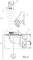
- this component is an inductive integrated in the handle 20 Antenna 25, which sends an electromagnetic code telegram in the KHz range, the is received by an inductive antenna 45 provided in the ID transmitter.
- This query 15 is, as Fig. 5 illustrates, of the antenna 45 via a receiving amplifier 41 to a microcontroller 43 forwarded.
- a power source 44 e.g. from one so-called button cell in the housing 42 of the ID transmitter 40 is made.
- the Power source 44 is also fed into the housing 42 of the ID transmitter 40 Transmitter 47, which is caused according to FIG. 3, a high-frequency coded response 46th which is in the MHz range and includes a code.
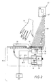
- FIG. 3 shows, in the vehicle 10 a radio signal 46 is received Receiver 16 arranged, the part of the already mentioned there Control unit 13 is.
- the controller 13 evaluates the response 46 and sends in If successful, a control pulse to the actuator 14.
- the actuator 14 then controls the coupling member 24 in its already described effective second position 30.2. This situation can be seen in FIG. 4. Then, as already mentioned, that Lock 30 in its unlocked position 30.2, whereupon the handle 20 successful can be pivoted 23.
- the actuator 14 consists of an electric motor, the reversal of the Lock 30 between the secured position 30.1 of Fig. 1 and the unlocked Position 30.2 shown in FIG. 4 causes. It is particularly advantageous, one on the To use piezoelectric principle acting engine, commonly referred to as "Piezomotor” is called. It is a piezoelectric Component that converts electrical energy into mechanical vibrations.
- the piezoelectric device is made in monolithic multilayer construction Ceramic plates with intermediate electrode layers made of copper, wherein the layer thickness of the electrodes is only a few micrometers.
- the Piezoelectric device is clamped with a resonator body, which is made of a Spring force is pressed against the driven element of the motor.
- This To be driven element can be made of a wheel, a rod or a bow element consist.
- the piezoelectric device vibrates, the free end performs of the resonator elliptical movements, the element to be driven move. Depending on the frequency of the vibrations, the Direction of movement of the element to be driven determined.
- the access authorization in the normal case of FIG. 1 to 4 assumes that the Vehicle battery 12 provides sufficient energy to those for the above Dialog 15, 46 relevant electronic components 13, 16, 25 to operate. But is the vehicle battery 12 empty and / or one of the failed for the Communication 15, 46 required components, so one is at a secured Position 30.1 of the lock 30 relies on an emergency device, which at the Invention is designed in a special way and described with reference to FIG. 6 becomes.
- the current source 44 of the ID transmitter 40 takes over the new Function to operate the actuator 14 in an emergency.
- the ID transmitter 40 in a visible from Fig. 6 special position 48 with respect to the vehicle 10 and its handle 20 are brought.
- the ID transmitter 40 is a special operation 49, as by an actuating arrow 49 is illustrated in FIG. 6.
- the Housing 42 of the ID transmitter 40 a special handle, in the present case off a button 33 which closes an electrical switch 34 when actuated.
- a special handle 33 could also serve other purposes handling used by the ID transmitter 40.
- the special operation in the case of others Handling results from an operation in a particular mode, which the Detects microcontroller 43 in the ID transmitter 40 as a special operation.
- the antenna 25 is in the charging circuit 28 the energy storage 26 connected.
- the antenna 45 in the ID transmitter 40 shows a new function beyond the effect in FIG. 2, namely as Energy donors for the originating from its current source 44 electrical energy serve.
- the energy transfer between the two antennas 45, 25 takes place with a superimposed code. Does the energy storage 26 a sufficient reached electrical level, the energy supply is terminated.
- a transponder 52 or a security controller that acts as an authentication member and communicates with the ID transmitter 40 located in the special position 48. These Communication is most easily accomplished by field damping (Challenged Response). Is the authentication of the ID transmitter 40 with the transponder 52nd successful, then the switch 36 is closed in the discharge circuit 29.
- the Discharge circuit 29 but also the bistable actuator 14 is connected the Function in the normal case has already been described previously. In case of emergancy However, this actuator 14 does not receive its energy from the defective one Vehicle battery 12, but of the charged via the ID transmitter energy storage 26.
- His mode of action is the same as in the normal case; the actuator 14 moves the coupling member 24 as shown in Fig. 3 and 4 already for the normal case was explained.
- the lock is from the secured position 30.1 as shown in FIG. 3rd Also in an emergency on the emergency power supply of the energy storage 26 in his from Fig. 4th shown, already described secured position 30.2.
- the castle 30 can be unlocked by operation 23 of the handle 20 and the door 11 is opened become.
- An ad can be the current electrical State of operation of its power source 44 indicate. This will be the owner's responsibility reminds to replace the power source 44 in the ID transmitter 40 in a timely manner or charge.
- the display 37 according to FIG. 5 is an LED used, which then lights up when in an emergency, the energy transfer according to FIG. 6 successfully completed.
- the indicated in Fig. 6 lighting 38 of the LED 37th informs the authorized user that he has the ID transmitter 40 from the described Special item 48 can take away again.
- the lighting 38 of the display 37 or Another indication can also signal to the user that already the lock 30 is unlocked as shown in FIG. 4 and therefore an operation 23 of the Handle 20 will be successful.
- the ID transmitter 40 may also have handles, which in an emergency, a Redirecting the lock 30 in the reverse direction cause; namely that Lock from its previously reached unlocked position 30.2 of Fig. 4 in to transfer its secured position 30.1 of Fig. 3.
- a Redirecting the lock 30 in the reverse direction cause namely that Lock from its previously reached unlocked position 30.2 of Fig. 4 in to transfer its secured position 30.1 of Fig. 3.
- This can e.g. then for the Authorized vehicle users may be interesting if he does so with a broken one Vehicle battery 12 wants to leave vehicle 10 again to seek help, in the meantime however unauthorized one wants to obstruct the entrance to the vehicle 10.
- the charging of the Energy storage 26 in the vehicle 10 causes, after successful authentication between the transponder 37 and the ID transmitter 40, the bistable actuator 14 in the described other position 30.1 of Fig. 3 moved back.
Landscapes
- Engineering & Computer Science (AREA)
- Mechanical Engineering (AREA)
- Computer Networks & Wireless Communication (AREA)
- Physics & Mathematics (AREA)
- General Physics & Mathematics (AREA)
- Lock And Its Accessories (AREA)
Abstract
Die Erfindung richtet sich auf eine Vorrichtung, die zum Betätigen eines Schlosses
an einer Tür (11) oder einer Klappe eines Fahrzeugs dient. An der Türaußenseite
befindet sich ein Griff (20), der über eine Wirkverbindung mit einem in der
Fahrzeugtür (11) befindlichen Schloss steht. Im Normalfall kann das Schloss durch
Fernbedienung zwischen seiner gesicherten und entsicherten Position umgesteuert
werden, wofür ein ID-Geber (40) verwendet wird, der mit dem Fahrzeug
kommuniziert. Wenn die elektrische Betätigung versagt, weil z.B. die
Fahrzeugbatterie ausgefallen ist, so schlägt die Erfindung als Not-Einrichtung vor,
den ID-Geber (40) als aktiven Teil dabei zu verwenden. Die Erfindung nutzt die
elektrische Energie in der Stromquelle (44) des ID-Gebers (40), um einen auch im
Normalfall zur Umsteuerung des Schlosses dienenden Aktuator zu betätigen. Dazu
genügt es, einen entsprechenden elektrischen Speicher (26) im Fahrzeug vorzusehen,
der von der Stromquelle (44) dann aufgeladen wird und bei Erreichen eines
ausreichenden Füllstandes zur Umsteuerung des Aktuators im Notfall genutzt wird, (Fig. 6).

Description
Die Erfindung richtet sich auf eine Vorrichtung der im Oberbegriff des Anspruches 1 angegebenen Art. An der Tür-Außenseite sitzt ein Griff, der in Wirkverbindung mit dem Schloss steht. Das Schloss kann zwischen einer gesicherten Position, wo die Griffbetätigung wirkungslos ist, in eine entsicherte Position überführt werden, wo eine Griffbetätigung erfolgreich ist und mittels des Griffs ein Öffnen der Tür erlaubt. Zwischen dem Fahrzeug und einem Identifikationsgeber, der nachfolgend kurz "ID-Geber" genannt wird, findet eine Kommunikation mittels Codesignalen statt. Diesen ID-Geber trägt der berechtigte Fahrzeugbenutzer bei sich. Zu dieser Kommunikation sind eine ruhende Batterie im Fahrzeug und eine tragbare Stromquelle im ID-Geber erforderlich. Im Normalfall, wenn die elektronische Einrichtung funktioniert, betreibt die Fahrzeugbatterie einen im Fahrzeug befindlichen Aktuator, welcher für die Umsteuerung zwischen der Entsicherung und/oder Sicherung des Schlosses dient.The invention is directed to a device that in the preamble of claim 1 specified type. On the outside of the door sits a handle, which is in operative connection with the castle stands. The lock can be between a secured position where the Handle operation is ineffective, be transferred to an unlocked position, where a handle operation is successful and allows the handle to open the door. Between the vehicle and an identification transmitter, hereinafter referred to as "ID transmitter" is called, a communication takes place by means of code signals. this ID transmitter is carried by the authorized vehicle user. To this communication are a dormant battery in the vehicle and a portable power source in the ID transmitter required. Normally, when the electronic device works, operates the vehicle battery an in-vehicle actuator, which for the Reversal between the release and / or securing the lock is used.
Wenn aber die elektrische Einrichtung versagt, weil z.B. die Fahrzeugbatterie leer ist, muss eine Not-Einrichtung vorgesehen sein, die es auch im Notfall erlaubt, das Schloss zu entsichern und/oder zu sichern. Im Stand der Technik wurde dafür auf mechanischem Wege wirkende Einrichtungen verwendet. Der berechtigte Fahrzeugbenutzer verfügte über einen mechanischen Notschlüssel, der bei Nichtgebrauch aus praktischen Gründen im Bereich des ID-Gebers aufbewahrt wurde. Weiterhin musste für den Notschlüssel ein Schließzylinder an der Tür bzw. Klappe des Fahrzeugs vorgesehen sein, in den der Schlüssel im Notfall eingesteckt werden musste, um auf diese Weise die Zugangsberechtigung des Notschlüssel-Benutzers zu ermitteln. Schließlich war noch ein mechanisches Gestänge zwischen dem Schließzylinder und dem Schloss erforderlich, über welches im Erfolgsfall durch Drehen des Notschlüssels im Schließzylinder ein Steuerimpuls zum Entsichern und/oder Sichern des Schlosses geleitet werden konnte. Schließlich mussten am Schloss außer einem Eingang für den elektrisch betriebenen Aktuator auch noch mechanische Eingänge für das Gestänge des Schließzylinders vorgesehen sein. Diese bekannte Not-Einrichtung erforderte somit zahlreiche Bauteile, die für sich hergestellt und montiert werden mussten, was zeitaufwendig war. Außerdem erforderten die vorgenannten zahlreichen Bauteile Platz, der dann für andere wichtige Elemente der Vorrichtung nicht mehr zur Verfügung stand.But if the electrical device fails because e.g. the vehicle battery is empty is an emergency facility must be provided, which allows it in an emergency, the Lock to release and / or secure. In the prior art was for used mechanical means acting. The authorized Vehicle users had a mechanical emergency key included in the Not stored for practical reasons in the area of the ID transmitter has been. Furthermore, had for the emergency key a lock cylinder on the door or Be provided flap of the vehicle, in which the key inserted in an emergency had to be in this way the access authorization of the emergency key user to investigate. Finally, there was still a mechanical linkage between the lock cylinder and the lock required, about which in case of success by turning the emergency key in the lock cylinder a control pulse for unlocking and / or securing the lock could be directed. Finally, at the Lock except an input for the electrically operated actuator also still be provided mechanical inputs for the linkage of the lock cylinder. These known emergency device thus required numerous components that stand alone had to be manufactured and mounted, which was time consuming. Furthermore required the aforementioned numerous components space, which then for others important elements of the device was no longer available.
Der Erfindung liegt die Aufgabe zugrunde, eine zuverlässige Vorrichtung der im Oberbegriff von Anspruch 1 genannten Art zu entwickeln, die einfacher und platzsparender ausgebildet ist. Dies wird erfindungsgemäß durch die im Anspruch 1 angeführten Maßnahmen erreicht, denen folgende besondere Bedeutung zukommt.The invention has for its object to provide a reliable device in the To develop preamble of claim 1 mentioned type, the simpler and is designed to save space. This is inventively by the in claim 1 achieved the following special importance.
Die Erfindung schlägt vor, im Notfall die elektrische Energie der Stromquelle im ID-Geber zur elektrischen Betätigung des Aktuators zu verwenden. Dann kann im Notfall, wie im Normalfall, auf elektrischem Weg das Schloss zwischen seiner Sicherungs- und Entsicherungsstellung umgesteuert werden. Damit wird der übliche tragbare ID-Geber ein aktiver Teil der erfindungsgemäßen Not-Einrichtung. Bei der Erfindung entfallen alle mechanischen Einrichtungen und alle mechanischen Identifikationsmittel, die bei der bekannten Not-Einrichtung erforderlich waren. Der im Stand der Technik dafür erforderliche Platz wird bei der Erfindung eingespart. Bis auf wenige raumsparende elektrische Bauteile, wie den Energiespeicher im Fahrzeug, sind bei der Erfindung keine zusätzlichen mechanischen Not-Betätigungsmittel erforderlich. Die erfindungsgemäße Noteinrichtung kann z.B. in folgender Weise ausgebildet sein. The invention proposes, in an emergency, the electrical energy of the power source in the ID transmitter to use for electrical actuation of the actuator. Then in the Emergency, as is normal, by electrical means the lock between his Locking and Entsicherungsstellung be reversed. This will be the usual portable ID transmitter an active part of the emergency device according to the invention. In the Invention accounts for all mechanical devices and all mechanical Identification means that were required in the known emergency device. Of the Space required in the prior art is saved in the invention. To to a few space-saving electrical components, such as the energy storage in the vehicle, are no additional mechanical emergency actuation means in the invention required. The emergency device according to the invention may e.g. in the following way be educated.
Bei der Erfindung genügt es, den ID-Geber in eine bestimmte Sonderposition gegenüber dem Fahrzeug zu bringen und/oder am ID-Geber oder Fahrzeug eine Sonderbetätigung auszulösen, damit elektrische Energie aus der Stromquelle des ID-Gebers in einen im Fahrzeug angeordneten Energiespeicher fließt. Wenn der Energiespeicher einen ausreichenden elektrischen Füllstand erlangt hat, kann er entladen werden und dabei den Aktuator in üblicher Weise betätigen.In the invention, it is sufficient, the ID transmitter in a particular special position towards the vehicle and / or at the ID transmitter or vehicle Special operation trigger, so that electrical energy from the power source of the ID transmitter flows in an arranged in the vehicle energy storage. If the Energy storage has achieved a sufficient electrical level, he can be discharged while pressing the actuator in the usual way.
Als passiver Teil der Not-Einrichtung können bei der Erfindung, außer dem Energiespeicher, die bisherigen elektrischen Einrichtungen verwendet werden, die schon im Normalfall zum Betrieb des Aktuators und zur Weiterleitung des Steuerimpulses bis zum Schloss erforderlich sind.As a passive part of the emergency device can in the invention, except the Energy storage, the previous electrical equipment used, the already normally for the operation of the actuator and for forwarding the Control pulses are required until the lock.
Weitere Maßnahmen und Vorteile der Erfindung ergeben sich aus den Unteransprüchen, der nachfolgenden Beschreibung und den Zeichnungen. In den Zeichnungen ist die Erfindung schematisch in einem Ausführungsbeispiel dargestellt. Es zeigen:
- Fig. 1
- schematisch den Verriegelungszustand der geschlossenen Tür eines Fahrzeugs in der ersten Phase einer Normalbetätigung, wo ein berechtigter Fahrzeugbenutzer sich dem Fahrzeug nähert, der den ID-Geber bei sich trägt,
- Fig. 2
- die nächste Betriebsphase, wo das Fahrzeug Codesignale an den ID-Geber gibt, um die Zugangsberechtigung des Fahrzeugbenutzers zu ermitteln,
- Fig. 3
- die nachfolgende Betriebsphase, wo der ID-Geber antwortet und die Antwort im Fahrzeug zur Ermittlung der Zugangsberechtigung ausgewertet wird,
- Fig. 4
- die letzte Phase der Normalbetätigung beim Öffnen der Tür, wo nach Feststellung der Zugangsberechtigung das Schloss auf elektrischem Weg entsichert wird und daher eine Betätigung des Griffes erfolgreich ist, um das Schloss zu entriegeln und die Tür zu öffnen,
- Fig. 5
- das Schaltbild eines bei der erfindungsgemäßen Vorrichtung verwendbaren ID-Gebers mit den wichtigsten Bauteilen, und
- Fig. 6
- die Fahrzeugtür bei Betätigung im Notfall mit den dafür vorgesehenen elektrischen Steuermitteln, die es erlauben, den ID-Geber als aktiven Teil der erfindungsgemäßen Not-Einrichtung zu verwenden.
- Fig. 1
- schematically illustrates the locked state of the closed door of a vehicle in the first phase of a normal operation where an authorized vehicle user approaches the vehicle carrying the ID transmitter,
- Fig. 2
- the next phase of operation, where the vehicle gives code signals to the ID transmitter in order to determine the access authorization of the vehicle user,
- Fig. 3
- the subsequent operating phase, where the ID transmitter responds and the response in the vehicle is evaluated to determine the access authorization,
- Fig. 4
- the last phase of the normal operation when the door is opened, where, once the access authorization has been established, the lock is unlocked by electrical means and therefore an operation of the handle succeeds in unlocking the lock and opening the door,
- Fig. 5
- the diagram of a usable in the inventive device ID transmitter with the most important components, and
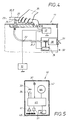
- Fig. 6
- the vehicle door when operated in an emergency with the appropriate electrical control means, which allow to use the ID transmitter as an active part of the emergency device according to the invention.
Im Schema von Fig. 1 sind vom Fahrzeug 10 lediglich eine Tür 11 und eine
Fahrzeugbatterie 12 gezeigt, welche ein elektrisches Steuergerät 13 und über dieses
Steuergerät 13 einen Aktuator 14 mit elektrischer Energie versorgt. An der
Außenseite 18 der Tür 11 ist ein Griff 20 angeordnet, der an einem Träger 21
schwenkbar oder klappbeweglich angelenkt ist. Der Träger 21 dient zur nicht näher
gezeigten Befestigung der ganzen, abschließend in Fig. 6 beschriebenen Griff-Baugruppe
50 im Türinneren 19. Im Türinneren 19 befindet sich auch ein Schloss 30,
welches mit einer aus der Tür herausragenden Drehfalle 31 herausragt. Im
verriegelten Zustand der Tür 11 gemäß Fig. 1 hält die Drehfalle einen Schließbolzen
32 fest, der an einem nicht näher gezeigten Türpfosten sitzt.In the diagram of Fig. 1 are of the
Das Schloss 30 kann sich in einer "gesicherten Position" befinden, wo die
Griffbetätigung wirkungslos ist. Das ist in Fig. 1 anhand eines Kupplungsglieds 24
veranschaulicht, das dort die durch die Hilfslinie 30.1 verdeutlichte Position
einnimmt. Zwischen dem Griff und dem Schloss 30 befindet sich eine in der Regel
mechanische Wirkverbindung 22, die dann unterbrochen bzw. entkuppelt ist, wenn
das Kupplungsglied 24 sich in der vorgenannten gesicherten Position 30.1 befindet.
Solange die gesicherte Position 30.1 vorliegt, wird eine Betätigung des Griffs 20
durch Unbefugte nicht auf das Schloss 30 übertragen. In Fig. 1 befindet sich der
Griff 20 in einer durch eine Hilfslinie 20.1 veranschaulichten "Ruhelage", die durch
am Griff 20 vorgesehene, nicht näher gezeigte Federmittel und Endanschläge
bestimmt ist. The
Das Schloss 30 kann aber, wie anhand der Fig. 4 veranschaulicht ist, sich in einer
"gesicherten Position" befinden, wo die Wirkverbindung 22 zwischen Griff 20 und
Schloss 30 geschlossen ist. Dies ist in Fig. 4 durch eine entsprechende Hilfslinie 30.2
am Kupplungsglied 24 veranschaulicht. In diesem Fall wird der Griff 20 von einer
menschlichen Hand 35 erfasst und im Sinne des Schwenkpfeils 23 von Fig. 5
betätigt, dann wird das Schloss 30 entriegelt. Der Griff befindet sich dann in seiner
durch eine Hilfslinie 20.2 in Fig. 5 veranschaulichten Arbeitslage 20.2. Bei der
Entriegelung gibt die Drehfalle 31 den Schließbolzen 32 frei. Die Tür 11 kann
mittels des Griffs 20 geöffnet werden.However, the
Liegt die gesicherte Position 30.1 von Fig. 1 vor, so sorgt ein sogenanntes "Keyless
Entry System" dafür, das nur berechtigte Personen Zugang erlangen. Dies geschieht
durch fernwirksame Kommunikation zwischen dem Fahrzeug 10 und einem im Besitz
der berechtigten Person befindlichen ID-Gebers 40, dessen wesentlicher Aufbau
anhand der Fig. 5 später näher erläutert wird. Der ID-Geber ist für dieses Fahrzeug
10 passend individualisiert. Wie diese Kommunikation im Normalfall erfolgen kann,
wird anhand der Fig. 1 bis 3 in drei Betriebsschritten erläutert.If the secured position 30.1 of FIG. 1 is present, a so-called "keyless
Entry System ", which only authorized persons gain access to
through remote effective communication between the
In Fig. 1 wird angenommen, dass das Fahrzeug steht und, wie bereits erwähnt wurde,
die Tür 11 verriegelt und das Schloss 30 gesichert ist. Im Normalfall wird, unter
Nutzung der Fahrzeugbatterie 12 ein elektrisches Feld 17 um den Griff 20 herum
aufgebaut. Realisiert wird das durch nicht näher gezeigte kapazitive Sensoren, die
ansprechen, wenn sich eine Hand dem Griff 20 nähert. Das ist in Fig. 1 durch eine
ins elektrische Feld 17 gelangende menschliche Hand 35 veranschaulicht. Der ID-Geber
40 spielt im Betriebszustand von Fig. 1 zunächst noch keine Rolle.In Fig. 1 it is assumed that the vehicle is stationary and, as already mentioned,
the
Anstelle eines elektrischen Feldes 17 könnten andere, den Außenbereich des
Fahrzeugs 10 beobachtende Überwachungssysteme benutzt werden. Es eignen sich
z.B. Lichtschranken. Solche Lichtschranken können auch auf den Bereich des Griffes
20 beschränkt sein.Instead of an
Wenn durch Veränderung des um den Griff 20 aufgebauten elektrischen Feldes 17
die erwähnten kapazitiven Sensoren feststellen, dass sich eine Hand 35 nähert, dann
wird im Fahrzeug 10 ein elektrischer Bauteil 25 geweckt, das eine Abfrage 15 startet. If by changing the built around the
Dieses Bauteil ist im vorliegenden Fall eine im Griff 20 integrierte induktive
Antenne 25, die ein elektromagnetisches Codetelegramm im KHz-Bereich sendet, das
von einer im ID-Geber vorgesehenen induktiven Antenne 45 empfangen wird. Das ist
in Fig. 2 dargestellt. Diese Abfrage 15 wird, wie Fig. 5 verdeutlicht, von der Antenne
45 über einen Empfangsverstärker 41 an einen Mikrocontroller 43 weitergeleitet. Der
Mikrocontroller 43 ist an eine Stromquelle 44 angeschlossen, die z.B. aus einer
sogenannten Knopfzelle im Gehäuse 42 des ID-Gebers 40 besteht. Von der
Stromquelle 44 gespeist ist auch ein im Gehäuse 42 des ID-Gebers 40 angeordneter
Sender 47, der gemäß Fig. 3 veranlasst wird, eine hochfrequente codierte Antwort 46
abzugeben, die im MHz-Bereich liegt und einen Code beinhaltet.In the present case, this component is an inductive integrated in the
Wie Fig. 3 zeigt, ist im Fahrzeug 10 ein dieses Funksignal 46 aufnehmender
Empfänger 16 angeordnet, der Bestandteil des bereits erwähnten dortigen
Steuergeräts 13 ist. Das Steuergerät 13 wertet die Antwort 46 aus und sendet im
Erfolgsfall einen Steuerimpuls an den Aktuator 14. Der Aktuator 14 steuert daraufhin
das Kupplungsglied 24 in seine bereits beschriebene wirksame zweite Position 30.2.
Diese Situation ist in Fig. 4 zu erkennen. Dann ist, wie bereits erwähnt wurde, das
Schloss 30 in seiner entsicherten Position 30.2, worauf der Griff 20 erfolgreich
schwenkbetätigt 23 werden kann.As FIG. 3 shows, in the vehicle 10 a
Der Aktuator 14 besteht aus einem elektrischen Motor, der die Umsteuerung des
Schlosses 30 zwischen der gesicherten Position 30.1 von Fig. 1 und der entsicherten
Position 30.2 gemäß Fig. 4 bewirkt. Besonders vorteilhaft ist es dabei, einen auf dem
piezoelektrischen Prinzip wirkenden Motor zu verwenden, der üblicherweise als
"Piezomotor" bezeichnet wird. Es handelt sich dabei um ein piezoelektrisches
Bauelement, das elektrische Energie in mechanische Vibrationen umwandelt. Das
piezoelektrische Bauelement ist in monolithischer Vielschichtbauweise aus
Keramikplatten mit dazwischen liegenden Elektrodenschichten aus Kupfer aufgebaut,
wobei die Schichtdicke der Elektroden nur wenige Mikrometer beträgt. Das
piezoelektrische Bauelement ist mit einem Resonanzkörper verspannt, der von einer
Federkraft gegen das anzutreibende Element des Motors gedrückt wird. Dieses
anzutreibende Element kann aus einem Rad, einem Stab oder einem Bogenelement
bestehen. Wenn das piezoelektrische Bauelement schwingt, vollführt das freie Ende
des Resonanzkörpers elliptische Bewegungen aus, die das anzutreibende Element
bewegen. In Abhängigkeit von der Frequenz der Schwingungen wird die
Bewegungsrichtung des anzutreibenden Elements bestimmt.The
Die Zugangsberechtigung im Normalfall gemäß Fig. 1 bis 4 setzt voraus, dass die
Fahrzeugbatterie 12 ausreichend Energie liefert, um die für den vorbeschriebenen
Dialog 15, 46 maßgeblichen elektronischen Bauteile 13, 16, 25 betreiben zu können.
Ist aber die Fahrzeugbatterie 12 leer und/oder versagt eines der für die
Kommunikation 15, 46 erforderlichen Bauteile, so ist man bei einer gesicherten
Position 30.1 des Schlosses 30 auf eine Not-Einrichtung angewiesen, die bei der
Erfindung in besonderer Weise ausgebildet ist und anhand der Fig. 6 beschrieben
wird.The access authorization in the normal case of FIG. 1 to 4 assumes that the
Bei der Erfindung übernimmt die Stromquelle 44 des ID-Gebers 40 die neue
Funktion, im Notfall den Aktuator 14 zu betreiben. Dazu muss zunächst der ID-Geber
40 in eine aus Fig. 6 ersichtliche Sonderposition 48 bezüglich des Fahrzeugs
10 bzw. seines Griffs 20 gebracht werden. Im dargestellten Ausführungsbeispiel
erfolgt am ID-Geber 40 eine Sonderbetätigung 49, wie durch einen Betätigungspfeil
49 in Fig. 6 veranschaulicht ist. Dazu besitzt, wie auch Fig. 5 erkennen lässt, das
Gehäuse 42 des ID-Gebers 40 eine Sonderhandhabe, die im vorliegenden Fall aus
einem Taster 33 besteht, der bei Betätigung einen elektrischen Schalter 34 schließt.
Statt einer Sonderhandhabe 33 könnten auch anderen Zwecken dienende Handhaben
vom ID-Geber 40 dafür verwendet werden. Die Sonderbetätigung im Fall anderer
Handhaben ergibt sich durch eine Betätigung in einem bestimmten Modus, den der
Mikrocontroller 43 im ID-Geber 40 als Sonderbetätigung erkennt.In the invention, the
In der Sonderposition 48 von Fig. 6 liegt eine induktive Kopplung der Antenne 45
vom ID-Geber 40 mit der Antenne 25 im Türgriff 20 vor. Nach Auslösen der
Sonderbetätigung 49 wird eine elektrische Verbindung zwischen der Stromquelle 44
und der induktiven Antenne 45 geschlossen. Dies erfolgt, wie Fig. 5 erkennen lässt,
über eine Sendeendstufe 51, die vom Mikrocontroller 43 eingeschaltet wird.
Zwischen der geberseitigen Antenne 45 und der fahrzeugseitigen Antenne 25 wird
auf induktivem Wege elektrische Energie übertragen und der Kondensator 26 im
Fahrzeug aufgeladen. Die von der fahrzeugseitigen Antenne 25 kommenden
Leitungen werden über einen Gleichrichter 27 zum Kondensator 26 geführt, der als
Speicher für elektrische Energie dient und daher nachfolgend kurz als
"Energiespeicher" bezeichnet werden soll. Bei der Erfindung hat die fahrzeugseitige
Antenne 25, abgesehen von ihrer im Zusammenhang mit Fig. 2 bereits gezeigten und
vorausgehend beschriebenen Wirkung, im Notfall die neue Funktion als
"Energieempfänger" zu fungieren. Deshalb ist die Antenne 25 im Ladestromkreis 28
des Energiespeichers 26 geschaltet. Natürlich erhält auch die Antenne 45 im ID-Geber
40 eine neue, über die Wirkung in Fig. 2 hinausgehende Funktion, nämlich als
Energiespender für die von seiner Stromquelle 44 stammende elektrische Energie zu
dienen. Die Energieübertragung zwischen den beiden Antennen 45, 25 erfolgt mit
einem überlagerten Code. Hat der Energiespeicher 26 einen ausreichenden
elektrischen Füllstand erlangt, so wird die Energieeinspeisung beendet.In the
Wie Fig. 6 zeigt, ist ein im Entladestromkreis 29 auf der anderen Seite des
Energiespeichers 26 befindlicher elektrischer Schalter 36 normalerweise offen. Im
Bereich des Griffs 20, vorzugsweise in den Griff 20 integriert, ist ein Transponder 52
oder ein Security Controller angeordnet, der als Authentifizierungsglied fungiert und
mit dem in der Sonderposition 48 befindlichen ID-Geber 40 kommuniziert. Diese
Kommunikation erfolgt am einfachsten durch eine Feldbedämpfung (Challenged
Response). Ist die Authentisierung des ID-Gebers 40 mit dem Transponder 52
erfolgreich, dann wird der Schalter 36 im Entladestromkreis 29 geschlossen. Im
Entladestromkreis 29 ist aber auch der bistabile Aktuator 14 geschaltet, dessen
Funktion beim Normalfall bereits vorausgehend beschrieben worden ist. Im Notfall
empfängt dieser Aktuator 14 seine Energie aber nicht von der defekten
Fahrzeugbatterie 12, sondern von dem über den ID-Geber geladenen Energiespeicher
26. Seine Wirkungsweise ist aber die Gleiche, wie im Normalfall; der Aktuator 14
bewegt das Kupplungsglied 24 so, wie in Fig. 3 und 4 bereits für den Normalfall
erläutert wurde. Das Schloss wird von der gesicherten Position 30.1 gemäß Fig. 3
auch im Notfall über die Notversorgung des Energiespeichers 26 in seine aus Fig. 4
ersichtliche, bereits beschriebene entsicherte Position 30.2 überführt. Das Schloss 30
kann durch Betätigung 23 der Handhabe 20 entriegelt und die Tür 11 geöffnet
werden.As shown in FIG. 6, one in the
Man kann die vorbeschriebene Sonderbetätigung 49 vermeiden, wenn man im
Fahrzeug 10 einen Signalgeber und im ID-Geber 40 einen auf dieses Signal dann
ansprechenden Sensor anordnet, wenn sich der ID-Geber 40 in der beschriebenen
Sonderposition 48 befindet. Dann spricht der Sensor auf dieses Signal an und schaltet
dann den von der Stromquelle 44 kommenden elektrischen Strom ein, der, gemäß
Fig. 5, dann über die Sendestufe 51 zur induktiven Antenne 45 fließt und die
geschilderte Energieübertragung in den fahrzeugseitigen Energiespeicher 26 bewirkt.
Es empfiehlt sich den vorgenannten Signalgeber als Permanentmagneten auszubilden
und einen Reed-Kontakt als Sensor zu benutzen. In der Sonderposition 48 des ID-Gebers
40 kommt der dort befindliche Reed-Kontakt in den Wirkbereich des
fahrzeugseitigen Permanentmagneten und schaltet die elektrische Verbindung zur
Stromquelle 44 im ID-Geber 40 ein. Den Permanentmagneten sollte man im Bereich
des Griffes vorsehen, wenn, wie im Ausführungsbeispiel, auch die fahrzeugseitige
Antenne 25 dort angeordnet ist.One can avoid the above-described
Am Gehäuse können eine oder mehrere Anzeigen vorgesehen sein, die verschiedene
Betriebszustände anzeigen. Eine Anzeige kann den aktuellen elektrischen
Betriebszustand seiner Stromquelle 44 angeben. Dadurch wird der Besitzer daran
erinnert, die Stromquelle 44 im ID-Geber 40 rechtzeitig auszuwechseln oder
aufzuladen. Im vorliegenden Fall wird als Anzeige 37 gemäß Fig. 5 eine LED
benutzt, die dann aufleuchtet, wenn im Notfall die Energieübertragung gemäß Fig. 6
erfolgreich beendet worden ist. Das in Fig. 6 angedeutete Aufleuchten 38 der LED 37
teilt dem berechtigten Benutzer mit, dass er den ID-Geber 40 aus der geschilderten
Sonderposition 48 wieder wegnehmen kann. Das Aufleuchten 38 der Anzeige 37 oder
über eine weitere Anzeige kann dem Benutzer auch signalisieren, dass auch schon
das Schloss 30 gemäß Fig. 4 entsichert ist und daher eine Betätigung 23 der
Handhabe 20 erfolgreich sein wird.On the housing one or more displays may be provided, the different
Show operating states. An ad can be the current electrical
State of operation of its
Der ID-Geber 40 kann aber auch Handhaben aufweisen, die im Notfall auch eine
Umsteuerung des Schlosses 30 im umgekehrten Sinn herbeiführen; nämlich das
Schloss aus seiner vorausgehend erreichten entsicherten Position 30.2 von Fig. 4 in
seine gesicherte Position 30.1 von Fig. 3 zu überführen. Das kann z.B. dann für den
berechtigten Fahrzeugbenutzer interessant sein, wenn er das mit einer defekten
Fahrzeugbatterie 12 versehene Fahrzeug 10 wieder verlassen will, um Hilfe zu holen,
in der Zwischenzeit aber Unbefugten den Zugang zum Fahrzeug 10 versperren will.
Dafür könnte auch die verfügbare Sonderhandhabe 33 dienen, wenn man ihnen und
den zugehörigen Elementen eine sogenannte "Toggle-Funktion" gibt. In diesem Fall
wird bei einer erneuten Sonderbetätigung 49, die wieder den Ladevorgang des
Energiespeichers 26 im Fahrzeug 10 bewirkt, nach erfolgreicher Authentisierung
zwischen dem Transponder 37 und dem ID-Geber 40 der bistabile Aktuator 14 in die
geschilderte andere Position 30.1 von Fig. 3 zurückbewegt.The
Es empfiehlt sich zumindest all jene Glieder, die zur erfindungsgemäßen
Notbetätigung gemäß Fig. 6 dienen, in einer vormontierten Griff-Baugruppe 50
zusammenzufassen, in welche auch die üblichen zum Griff 20 gehörenden weiteren
Elemente, wie der Träger 21, integriert ist. Der Aktuator 14 der, wie erwähnt wurde,
auch für den Normalfall benötigt werden kann, ist zweckmäßigerweise im Bereich
des Schlosses 30, außerhalb dieser Griff-Baugruppe 50 angeordnet. In diesem Fall
genügt es für elektrische Anschlüsse in der Leitung 39 im vorbeschriebenen
Entladestromkreis 29 zu sorgen, die beim Einbau der Griff-Baueinheit 50 schnell und
zuverlässig an den am Schloss befindlichen Aktuator 14 angeschlossen werden
können.It is recommended at least all those members that are for inventive
Serve emergency operation shown in FIG. 6, in a preassembled handle assembly 50th
in which also the usual belonging to the
Statt der geschilderten magnetischen Energieübertragung zwischen den induktiven
Antennen 25, 45 von Fig. 6 könnte man auch eine galvanische Energieübertragung
benutzen. Dazu könnten am vorbeschriebenen Gehäuse 42 des ID-Gebers 40
elektrische Kontakte vorgesehen sein, die mit seiner Stromquelle 44 mindestens dann
in Verbindung stehen, wenn eine Sonderbetätigung 49 vorgenommen wird. Diesen
Kontakten können, was ebenfalls nicht näher gezeigt ist, elektrische Gegenkontakte
am Fahrzeug zugeordnet sein, die Bestandteil des vorbeschriebenen
Ladestromkreises 28 sind. Die Anordnung solcher Gegenkontakte könnte auch im
Bereich des Handgriffs 20 erfolgen. Instead of the described magnetic energy transfer between the
- 1010
- Fahrzeugvehicle
- 1111
- Tür an 10Door at 10
- 1212
- Fahrzeugbatterie in 10Vehicle battery in 10
- 1313
- elektrisches Steuergerät in 10electrical control unit in 10
- 1414
- Aktuator in 10, elektrischer Motor, PiezomotorActuator in 10, electric motor, piezo motor
- 1515
- elektromagnetische Abfrage von 25 an 40 (Fig. 2)electromagnetic query from 25 to 40 (Figure 2)
- 1616
- Empfänger von 13 (Fig. 3)Receiver of FIG. 13 (FIG. 3)
- 1717
- elektrisches Feld außerhalb von 10 (Fig. 1)electric field outside of 10 (Fig. 1)
- 1818
- Türaußenseite von 11 (Fig. 1)Outside of the door 11 (Fig. 1)
- 1919
- Türinneres von 11 (Fig. 1)Door interior of 11 (Fig. 1)
- 2020
- GriffHandle
- 20.120.1
- Ruhelage von 20 (Fig. 1)Resting position of 20 (Fig. 1)
- 20.220.2
- Arbeitslage von 20 (Fig. 4)Working position of 20 (Fig. 4)
- 2121
- Träger für 20 (Fig. 1)Carrier for 20 (Fig. 1)
- 2222
- mechanische Wirkverbindung zwischen 20 und 30 (Fig. 1)mechanical operative connection between 20 and 30 (FIG. 1)
- 2323
- Pfeil der Schwenkbetätigung von 20Arrow of swing actuation of 20
- 2424
- Kupplungsgliedfür 22 (Fig. 1)Coupling member for 22 (Fig. 1)
- 2525
- elektrischer Bauteil, induktive Antenne in 20 für 15 (Fig. 2)electrical component, inductive antenna in FIG. 20 for FIG. 15 (FIG. 2)
- 2626
- Kondensator in 28, Energiespeicher (Fig. 6)Capacitor in 28, energy storage (FIG. 6)
- 2727
- Gleichrichter (Fig. 6)Rectifier (FIG. 6)
- 2828
- Ladestromkreis für 26 (Fig. 6)Charging circuit for 26 (Figure 6)
- 2929
- Entladestromkreis von 26 (Fig. 6)Discharge Circuit of FIG. 26 (FIG. 6)
- 3030
- Schloss in 11Castle in 11th
- 30.130.1
- gesicherte Position von 30 (Fig. 1)secured position of 30 (Fig. 1)
- 30.230.2
- entsicherte Position von 30 (Fig. 4)unlocked position of 30 (Figure 4)
- 3131
- Drehfalle von 30 (Fig. 1, 4)Rotary latch of 30 (Fig. 1, 4)
- 3232
- Schließbolzen für 30 (Fig. 1, 4)Locking bolt for 30 (FIGS. 1, 4)
- 3333
- Sonderhandhabe, Taster an 40 (Fig. 5, 6) Special handle, pushbutton on 40 (Fig. 5, 6)
- 3434
- elektrischer Schalter für 33 (Fig. 5)electrical switch for 33 (Figure 5)
- 3535
- menschliche Handhuman hand
- 3636
- elektrischer Schalter in 29 (Fig. 6)electrical switch in Fig. 29 (Fig. 6)
- 3737
- Anzeige an 40, LED (Fig. 5, 6)Display on 40, LED (Fig. 5, 6)
- 3838
- Aufleuchten von 37 (Fig. 6)Lighting up 37 (Fig. 6)
- 3939
- elektrische Anschlüsse für 14 in 29 (Fig. 6)electrical connections for 14 in FIG. 29 (FIG. 6)
- 4040
- ID-Geber (Fig. 1)ID transmitter (Fig. 1)
- 4141
- Empfangsverstärker in 40 (Fig. 5)Receive Amplifier in FIG. 40 (FIG. 5)
- 4242
- Gehäuse von 40 (Fig. 5)Housing of 40 (Figure 5)
- 4343
- Mikrocontroller von 40 (Fig. 5)Microcontroller of 40 (Figure 5)
- 4444
- Stromquelle von 40 (Fig. 5)Power source of 40 (Figure 5)
- 4545
- elektrischer Bauteil, induktive Antenne in 40 (Fig. 2, 5, 6)electrical component, inductive antenna in FIG. 40 (FIGS. 2, 5, 6)
- 4646
- codierte Antwort von 45, Funksignal (Fig. 3)coded answer of 45, radio signal (Fig. 3)
- 4747
- Sender für 46 in 40 (Fig. 3, 5)Transmitter for 46 in 40 (Fig. 3, 5)
- 4848
- Sonderposition von 40 (Fig. 6)Special position of 40 (Fig. 6)
- 4949
- Pfeil der Sonderbetätigung von 33 (Fig. 6)Special operation arrow 33 (Fig. 6)
- 5050
- Griff-Baugruppe (Fig. 6)Handle assembly (Fig. 6)
- 5151
- Sendeendstufe (Fig. 5)Transmitting output stage (FIG. 5)
- 5252
- Transponder, Security ControllerTransponder, security controller
Claims (30)
wobei die Fahrzeugbatterie (12) einen Aktuator (14) im Fahrzeug (10) zur Entsicherung (30.2) und/oder Sicherung (30.1) des Schlosses (30) betreibt,
wherein the vehicle battery (12) operates an actuator (14) in the vehicle (10) for unlocking (30.2) and / or securing (30.1) the lock (30),
Applications Claiming Priority (2)
| Application Number | Priority Date | Filing Date | Title |
|---|---|---|---|
| DE102004007582 | 2004-02-17 | ||
| DE102004007582 | 2004-02-17 |
Publications (2)
| Publication Number | Publication Date |
|---|---|
| EP1564689A2 true EP1564689A2 (en) | 2005-08-17 |
| EP1564689A3 EP1564689A3 (en) | 2006-04-26 |
Family
ID=34684081
Family Applications (1)
| Application Number | Title | Priority Date | Filing Date |
|---|---|---|---|
| EP05000884A Withdrawn EP1564689A3 (en) | 2004-02-17 | 2005-01-18 | Method for operating a lock with back-up device for locking and/or unlocking the lock |
Country Status (1)
| Country | Link |
|---|---|
| EP (1) | EP1564689A3 (en) |
Cited By (14)
| Publication number | Priority date | Publication date | Assignee | Title |
|---|---|---|---|---|
| WO2014150649A1 (en) * | 2013-03-22 | 2014-09-25 | Utc Fire And Security Americas Corporation, Inc. | Electronic lock with selectable power sources |
| US9666004B2 (en) | 2014-12-24 | 2017-05-30 | Magna Closures S.P.A. | Electronic latch release backup system for a motor vehicle door |
| EP3217365A1 (en) * | 2016-03-10 | 2017-09-13 | iLOQ Oy | Near field communication tag |
| DE102017201785A1 (en) | 2017-02-03 | 2018-08-09 | Volkswagen Aktiengesellschaft | Vehicle lock device |
| WO2019030342A1 (en) * | 2017-08-11 | 2019-02-14 | Continental Automotive Gmbh | ACCESS ARRANGEMENT FOR ONE VEHICLE |
| WO2019030385A1 (en) * | 2017-08-11 | 2019-02-14 | Continental Automotive Gmbh | METHOD FOR OPERATING A ACCESS ARRANGEMENT FOR A VEHICLE |
| WO2019030334A1 (en) * | 2017-08-11 | 2019-02-14 | Continental Automotive Gmbh | MOBILE IDENTIFIER |
| WO2019086072A1 (en) * | 2017-11-03 | 2019-05-09 | Kiekert Ag | Emergency actuating device for a movable part of a vehicle |
| DE102009039637B4 (en) | 2008-09-04 | 2019-07-18 | GM Global Technology Operations LLC (n. d. Ges. d. Staates Delaware) | Locking system for a door of a motor vehicle |
| DE102018212407B3 (en) * | 2018-07-25 | 2019-09-12 | Volkswagen Aktiengesellschaft | Electronic door closing system |
| EP3581443A3 (en) * | 2018-04-20 | 2020-01-15 | Huf Hülsbeck & Fürst GmbH & Co. KG | Communication device for a vehicle for carrying out a contactless data transmission |
| DE102018124331A1 (en) * | 2018-10-02 | 2020-04-02 | Kiekert Aktiengesellschaft | Actuator for a moving part of a vehicle |
| EP3647130A1 (en) * | 2018-10-29 | 2020-05-06 | Toyota Jidosha Kabushiki Kaisha | Vehicle and portable device |
| DE102021128395A1 (en) | 2021-10-27 | 2023-04-27 | Elmos Semiconductor Se | Emergency unlocking system for electrically locked vehicle doors |
Family Cites Families (7)
| Publication number | Priority date | Publication date | Assignee | Title |
|---|---|---|---|---|
| IT1296295B1 (en) * | 1996-12-03 | 1999-06-25 | Aldo Biancone S R L | IMPROVEMENTS IN SECURITY LOCKS |
| DE19725667A1 (en) * | 1997-06-18 | 1998-12-24 | Marquardt Gmbh | Electronic key |
| DE19755093B4 (en) * | 1997-12-11 | 2013-03-28 | Continental Teves Ag & Co. Ohg | Energy receiving connection and release procedure |
| FR2776412B1 (en) * | 1998-03-17 | 2000-05-12 | Schlumberger Ind Sa | BIDIRECTIONAL DEVICE FOR TRANSFERRING ENERGY AND DATA BETWEEN TWO CIRCUITS WITHOUT ELECTRICAL CONNECTION |
| DE19936961A1 (en) * | 1999-08-05 | 2001-02-08 | Geze Gmbh | Electrically switchable locking device |
| WO2001023695A1 (en) * | 1999-09-30 | 2001-04-05 | Siemens Automotive Corporation | An electronic transmitter key to supply backup power for an electronic locking system |
| DE10208573A1 (en) * | 2002-02-21 | 2003-09-11 | Valeo Schalter & Sensoren Gmbh | Door handle for vehicle has mounted within it transmitting/receiving arrangement for radar system for detecting distances and/or directions of objects/persons in vicinity of motor vehicle |
-
2005
- 2005-01-18 EP EP05000884A patent/EP1564689A3/en not_active Withdrawn
Cited By (24)
| Publication number | Priority date | Publication date | Assignee | Title |
|---|---|---|---|---|
| DE102009039637B4 (en) | 2008-09-04 | 2019-07-18 | GM Global Technology Operations LLC (n. d. Ges. d. Staates Delaware) | Locking system for a door of a motor vehicle |
| CN105393285A (en) * | 2013-03-22 | 2016-03-09 | Utc消防和保安美国有限公司 | Electronic lock with selectable power sources |
| WO2014150649A1 (en) * | 2013-03-22 | 2014-09-25 | Utc Fire And Security Americas Corporation, Inc. | Electronic lock with selectable power sources |
| US9666004B2 (en) | 2014-12-24 | 2017-05-30 | Magna Closures S.P.A. | Electronic latch release backup system for a motor vehicle door |
| US9959691B2 (en) | 2014-12-24 | 2018-05-01 | Magna Closures S.P.A. | Electronic latch release backup system for a motor vehicle door |
| EP3217365A1 (en) * | 2016-03-10 | 2017-09-13 | iLOQ Oy | Near field communication tag |
| WO2017153514A1 (en) * | 2016-03-10 | 2017-09-14 | Iloq Oy | Near field communication tag |
| US11164407B2 (en) | 2016-03-10 | 2021-11-02 | Iloq Oy | Near field communication tag |
| DE102017201785A1 (en) | 2017-02-03 | 2018-08-09 | Volkswagen Aktiengesellschaft | Vehicle lock device |
| US20200216031A1 (en) | 2017-08-11 | 2020-07-09 | Continental Automotive Gmbh | Access arrangement for a vehicle |
| US11192525B2 (en) | 2017-08-11 | 2021-12-07 | Continental Automotive Gmbh | Access arrangement for a vehicle |
| WO2019030342A1 (en) * | 2017-08-11 | 2019-02-14 | Continental Automotive Gmbh | ACCESS ARRANGEMENT FOR ONE VEHICLE |
| WO2019030385A1 (en) * | 2017-08-11 | 2019-02-14 | Continental Automotive Gmbh | METHOD FOR OPERATING A ACCESS ARRANGEMENT FOR A VEHICLE |
| WO2019030334A1 (en) * | 2017-08-11 | 2019-02-14 | Continental Automotive Gmbh | MOBILE IDENTIFIER |
| US20200300006A1 (en) * | 2017-11-03 | 2020-09-24 | Kiekert Ag | Emergency actuating device for a movable part of a vehicle |
| DE102017125719A1 (en) * | 2017-11-03 | 2019-05-09 | Kiekert Ag | Emergency operating device for a moving part of a vehicle |
| WO2019086072A1 (en) * | 2017-11-03 | 2019-05-09 | Kiekert Ag | Emergency actuating device for a movable part of a vehicle |
| US11781350B2 (en) * | 2017-11-03 | 2023-10-10 | Kiekert Ag | Emergency actuating device for a movable part of a vehicle |
| EP3581443A3 (en) * | 2018-04-20 | 2020-01-15 | Huf Hülsbeck & Fürst GmbH & Co. KG | Communication device for a vehicle for carrying out a contactless data transmission |
| DE102018212407B3 (en) * | 2018-07-25 | 2019-09-12 | Volkswagen Aktiengesellschaft | Electronic door closing system |
| DE102018124331A1 (en) * | 2018-10-02 | 2020-04-02 | Kiekert Aktiengesellschaft | Actuator for a moving part of a vehicle |
| EP3647130A1 (en) * | 2018-10-29 | 2020-05-06 | Toyota Jidosha Kabushiki Kaisha | Vehicle and portable device |
| US11441528B2 (en) | 2018-10-29 | 2022-09-13 | Toyota Jidosha Kabushiki Kaisha | Vehicle and portable device |
| DE102021128395A1 (en) | 2021-10-27 | 2023-04-27 | Elmos Semiconductor Se | Emergency unlocking system for electrically locked vehicle doors |
Also Published As
| Publication number | Publication date |
|---|---|
| EP1564689A3 (en) | 2006-04-26 |
Similar Documents
| Publication | Publication Date | Title |
|---|---|---|
| DE19617038C2 (en) | Locking system, in particular for motor vehicles | |
| EP1023511B2 (en) | Closing device, in particular for motor vehicles | |
| DE19539852C1 (en) | Ignition key vehicle communication unit with at least one electronic key | |
| EP1564689A2 (en) | Method for operating a lock with back-up device for locking and/or unlocking the lock | |
| DE4403655C2 (en) | Electronic system for a motor-driven vehicle | |
| DE602004003947T2 (en) | ELECTRICALLY ACTUATING LOCKING ASSEMBLY FOR MOTOR VEHICLE | |
| EP3704675A1 (en) | Emergency actuating device for a movable part of a vehicle | |
| DE102008018906B4 (en) | Lock cylinder arrangement | |
| DE4228234A1 (en) | Door lock for motor vehicles | |
| WO2013160481A1 (en) | Electronic key, electronic closure system and a method for allowing an access authorisation | |
| EP1631792A1 (en) | Sensor for the detection of the position of a mechanical force-transmitting device | |
| DE10341215A1 (en) | Keyless locking system for automobile, has locked door opened by entry of code signal sequence via input element accessible from outside of vehicle | |
| EP0709534A1 (en) | Lock activated by an identity carrier | |
| WO2010106092A1 (en) | Arrangement for unlocking a lock | |
| WO2018001417A1 (en) | Locking arrangement, in particular door lock arrangement for a switchgear cabinet, and a corresponding method | |
| DE10007500A1 (en) | Motor vehicle door lock system detects approach/contact by detecting transmitted electromagnetic wave reflections, changes in wave field, changes in antenna electrical capacitance | |
| EP0877333B1 (en) | Apparatus for wireless transfer of energy and execution of an action | |
| DE4309006C2 (en) | Wireless data transmission device | |
| DE4330118C1 (en) | Remote-controllable access monitoring device, in particular for a motor vehicle | |
| EP1533450B1 (en) | A motor vehicle locking system | |
| DE19937915A1 (en) | Electronic key for remotely unlocking a motor vehicle has a power supply that can be interrupted to prevent transmission of an identification signal | |
| DE102006001478B4 (en) | door opener system | |
| EP1331331B1 (en) | Locking system, in particular for a motor vehicle | |
| DE10236957B4 (en) | Locking device for motor vehicles | |
| DE102005017577B4 (en) | Device for locking a motor vehicle |
Legal Events
| Date | Code | Title | Description |
|---|---|---|---|
| PUAI | Public reference made under article 153(3) epc to a published international application that has entered the european phase |
Free format text: ORIGINAL CODE: 0009012 |
|
| AK | Designated contracting states |
Kind code of ref document: A2 Designated state(s): AT BE BG CH CY CZ DE DK EE ES FI FR GB GR HU IE IS IT LI LT LU MC NL PL PT RO SE SI SK TR |
|
| AX | Request for extension of the european patent |
Extension state: AL BA HR LV MK YU |
|
| PUAL | Search report despatched |
Free format text: ORIGINAL CODE: 0009013 |
|
| AK | Designated contracting states |
Kind code of ref document: A3 Designated state(s): AT BE BG CH CY CZ DE DK EE ES FI FR GB GR HU IE IS IT LI LT LU MC NL PL PT RO SE SI SK TR |
|
| AX | Request for extension of the european patent |
Extension state: AL BA HR LV MK YU |
|
| STAA | Information on the status of an ep patent application or granted ep patent |
Free format text: STATUS: THE APPLICATION HAS BEEN WITHDRAWN |
|
| 18W | Application withdrawn |
Effective date: 20061018 |