EP3647130A1 - Vehicle and portable device - Google Patents
Vehicle and portable device Download PDFInfo
- Publication number
- EP3647130A1 EP3647130A1 EP19198013.5A EP19198013A EP3647130A1 EP 3647130 A1 EP3647130 A1 EP 3647130A1 EP 19198013 A EP19198013 A EP 19198013A EP 3647130 A1 EP3647130 A1 EP 3647130A1
- Authority
- EP
- European Patent Office
- Prior art keywords
- electric power
- power supply
- vehicle
- relay
- positive electrode
- Prior art date
- Legal status (The legal status is an assumption and is not a legal conclusion. Google has not performed a legal analysis and makes no representation as to the accuracy of the status listed.)
- Granted
Links
- 238000003860 storage Methods 0.000 claims abstract description 60
- 230000004913 activation Effects 0.000 claims description 9
- 238000003780 insertion Methods 0.000 claims description 6
- 230000037431 insertion Effects 0.000 claims description 6
- NGVDGCNFYWLIFO-UHFFFAOYSA-N pyridoxal 5'-phosphate Chemical compound CC1=NC=C(COP(O)(O)=O)C(C=O)=C1O NGVDGCNFYWLIFO-UHFFFAOYSA-N 0.000 description 32
- 230000004048 modification Effects 0.000 description 15
- 238000012986 modification Methods 0.000 description 15
- 239000007858 starting material Substances 0.000 description 11
- 238000012545 processing Methods 0.000 description 6
- 230000007246 mechanism Effects 0.000 description 5
- 238000004891 communication Methods 0.000 description 4
- 230000003213 activating effect Effects 0.000 description 3
- HBBGRARXTFLTSG-UHFFFAOYSA-N Lithium ion Chemical compound [Li+] HBBGRARXTFLTSG-UHFFFAOYSA-N 0.000 description 2
- 229910001416 lithium ion Inorganic materials 0.000 description 2
- 238000000034 method Methods 0.000 description 2
- 230000008569 process Effects 0.000 description 2
- 238000009877 rendering Methods 0.000 description 2
- PXHVJJICTQNCMI-UHFFFAOYSA-N Nickel Chemical compound [Ni] PXHVJJICTQNCMI-UHFFFAOYSA-N 0.000 description 1
- 238000002485 combustion reaction Methods 0.000 description 1
- 238000005520 cutting process Methods 0.000 description 1
- 230000000694 effects Effects 0.000 description 1
- 239000000446 fuel Substances 0.000 description 1
- 238000004519 manufacturing process Methods 0.000 description 1
- 239000002184 metal Substances 0.000 description 1
- 229910052751 metal Inorganic materials 0.000 description 1
- 229910000652 nickel hydride Inorganic materials 0.000 description 1
- 230000000452 restraining effect Effects 0.000 description 1
- 230000001360 synchronised effect Effects 0.000 description 1
Images


Classifications
-
- H—ELECTRICITY
- H02—GENERATION; CONVERSION OR DISTRIBUTION OF ELECTRIC POWER
- H02J—CIRCUIT ARRANGEMENTS OR SYSTEMS FOR SUPPLYING OR DISTRIBUTING ELECTRIC POWER; SYSTEMS FOR STORING ELECTRIC ENERGY
- H02J7/00—Circuit arrangements for charging or depolarising batteries or for supplying loads from batteries
- H02J7/0063—Circuit arrangements for charging or depolarising batteries or for supplying loads from batteries with circuits adapted for supplying loads from the battery
-
- F—MECHANICAL ENGINEERING; LIGHTING; HEATING; WEAPONS; BLASTING
- F02—COMBUSTION ENGINES; HOT-GAS OR COMBUSTION-PRODUCT ENGINE PLANTS
- F02N—STARTING OF COMBUSTION ENGINES; STARTING AIDS FOR SUCH ENGINES, NOT OTHERWISE PROVIDED FOR
- F02N11/00—Starting of engines by means of electric motors
- F02N11/08—Circuits or control means specially adapted for starting of engines
- F02N11/0862—Circuits or control means specially adapted for starting of engines characterised by the electrical power supply means, e.g. battery
- F02N11/0866—Circuits or control means specially adapted for starting of engines characterised by the electrical power supply means, e.g. battery comprising several power sources, e.g. battery and capacitor or two batteries
-
- B—PERFORMING OPERATIONS; TRANSPORTING
- B60—VEHICLES IN GENERAL
- B60R—VEHICLES, VEHICLE FITTINGS, OR VEHICLE PARTS, NOT OTHERWISE PROVIDED FOR
- B60R25/00—Fittings or systems for preventing or indicating unauthorised use or theft of vehicles
- B60R25/40—Features of the power supply for the anti-theft system, e.g. anti-theft batteries, back-up power supply or means to save battery power
-
- B—PERFORMING OPERATIONS; TRANSPORTING
- B60—VEHICLES IN GENERAL
- B60L—PROPULSION OF ELECTRICALLY-PROPELLED VEHICLES; SUPPLYING ELECTRIC POWER FOR AUXILIARY EQUIPMENT OF ELECTRICALLY-PROPELLED VEHICLES; ELECTRODYNAMIC BRAKE SYSTEMS FOR VEHICLES IN GENERAL; MAGNETIC SUSPENSION OR LEVITATION FOR VEHICLES; MONITORING OPERATING VARIABLES OF ELECTRICALLY-PROPELLED VEHICLES; ELECTRIC SAFETY DEVICES FOR ELECTRICALLY-PROPELLED VEHICLES
- B60L53/00—Methods of charging batteries, specially adapted for electric vehicles; Charging stations or on-board charging equipment therefor; Exchange of energy storage elements in electric vehicles
- B60L53/10—Methods of charging batteries, specially adapted for electric vehicles; Charging stations or on-board charging equipment therefor; Exchange of energy storage elements in electric vehicles characterised by the energy transfer between the charging station and the vehicle
- B60L53/14—Conductive energy transfer
- B60L53/18—Cables specially adapted for charging electric vehicles
-
- B—PERFORMING OPERATIONS; TRANSPORTING
- B60—VEHICLES IN GENERAL
- B60R—VEHICLES, VEHICLE FITTINGS, OR VEHICLE PARTS, NOT OTHERWISE PROVIDED FOR
- B60R16/00—Electric or fluid circuits specially adapted for vehicles and not otherwise provided for; Arrangement of elements of electric or fluid circuits specially adapted for vehicles and not otherwise provided for
- B60R16/02—Electric or fluid circuits specially adapted for vehicles and not otherwise provided for; Arrangement of elements of electric or fluid circuits specially adapted for vehicles and not otherwise provided for electric constitutive elements
- B60R16/03—Electric or fluid circuits specially adapted for vehicles and not otherwise provided for; Arrangement of elements of electric or fluid circuits specially adapted for vehicles and not otherwise provided for electric constitutive elements for supply of electrical power to vehicle subsystems or for
- B60R16/033—Electric or fluid circuits specially adapted for vehicles and not otherwise provided for; Arrangement of elements of electric or fluid circuits specially adapted for vehicles and not otherwise provided for electric constitutive elements for supply of electrical power to vehicle subsystems or for characterised by the use of electrical cells or batteries
-
- B—PERFORMING OPERATIONS; TRANSPORTING
- B60—VEHICLES IN GENERAL
- B60R—VEHICLES, VEHICLE FITTINGS, OR VEHICLE PARTS, NOT OTHERWISE PROVIDED FOR
- B60R25/00—Fittings or systems for preventing or indicating unauthorised use or theft of vehicles
- B60R25/01—Fittings or systems for preventing or indicating unauthorised use or theft of vehicles operating on vehicle systems or fittings, e.g. on doors, seats or windscreens
-
- B—PERFORMING OPERATIONS; TRANSPORTING
- B60—VEHICLES IN GENERAL
- B60R—VEHICLES, VEHICLE FITTINGS, OR VEHICLE PARTS, NOT OTHERWISE PROVIDED FOR
- B60R25/00—Fittings or systems for preventing or indicating unauthorised use or theft of vehicles
- B60R25/40—Features of the power supply for the anti-theft system, e.g. anti-theft batteries, back-up power supply or means to save battery power
- B60R25/403—Power supply in the vehicle
-
- B—PERFORMING OPERATIONS; TRANSPORTING
- B60—VEHICLES IN GENERAL
- B60W—CONJOINT CONTROL OF VEHICLE SUB-UNITS OF DIFFERENT TYPE OR DIFFERENT FUNCTION; CONTROL SYSTEMS SPECIALLY ADAPTED FOR HYBRID VEHICLES; ROAD VEHICLE DRIVE CONTROL SYSTEMS FOR PURPOSES NOT RELATED TO THE CONTROL OF A PARTICULAR SUB-UNIT
- B60W10/00—Conjoint control of vehicle sub-units of different type or different function
- B60W10/24—Conjoint control of vehicle sub-units of different type or different function including control of energy storage means
- B60W10/26—Conjoint control of vehicle sub-units of different type or different function including control of energy storage means for electrical energy, e.g. batteries or capacitors
-
- Y—GENERAL TAGGING OF NEW TECHNOLOGICAL DEVELOPMENTS; GENERAL TAGGING OF CROSS-SECTIONAL TECHNOLOGIES SPANNING OVER SEVERAL SECTIONS OF THE IPC; TECHNICAL SUBJECTS COVERED BY FORMER USPC CROSS-REFERENCE ART COLLECTIONS [XRACs] AND DIGESTS
- Y02—TECHNOLOGIES OR APPLICATIONS FOR MITIGATION OR ADAPTATION AGAINST CLIMATE CHANGE
- Y02T—CLIMATE CHANGE MITIGATION TECHNOLOGIES RELATED TO TRANSPORTATION
- Y02T10/00—Road transport of goods or passengers
- Y02T10/60—Other road transportation technologies with climate change mitigation effect
- Y02T10/70—Energy storage systems for electromobility, e.g. batteries
-
- Y—GENERAL TAGGING OF NEW TECHNOLOGICAL DEVELOPMENTS; GENERAL TAGGING OF CROSS-SECTIONAL TECHNOLOGIES SPANNING OVER SEVERAL SECTIONS OF THE IPC; TECHNICAL SUBJECTS COVERED BY FORMER USPC CROSS-REFERENCE ART COLLECTIONS [XRACs] AND DIGESTS
- Y02—TECHNOLOGIES OR APPLICATIONS FOR MITIGATION OR ADAPTATION AGAINST CLIMATE CHANGE
- Y02T—CLIMATE CHANGE MITIGATION TECHNOLOGIES RELATED TO TRANSPORTATION
- Y02T10/00—Road transport of goods or passengers
- Y02T10/60—Other road transportation technologies with climate change mitigation effect
- Y02T10/7072—Electromobility specific charging systems or methods for batteries, ultracapacitors, supercapacitors or double-layer capacitors
-
- Y—GENERAL TAGGING OF NEW TECHNOLOGICAL DEVELOPMENTS; GENERAL TAGGING OF CROSS-SECTIONAL TECHNOLOGIES SPANNING OVER SEVERAL SECTIONS OF THE IPC; TECHNICAL SUBJECTS COVERED BY FORMER USPC CROSS-REFERENCE ART COLLECTIONS [XRACs] AND DIGESTS
- Y02—TECHNOLOGIES OR APPLICATIONS FOR MITIGATION OR ADAPTATION AGAINST CLIMATE CHANGE
- Y02T—CLIMATE CHANGE MITIGATION TECHNOLOGIES RELATED TO TRANSPORTATION
- Y02T90/00—Enabling technologies or technologies with a potential or indirect contribution to GHG emissions mitigation
- Y02T90/10—Technologies relating to charging of electric vehicles
- Y02T90/14—Plug-in electric vehicles
Definitions
- the invention relates to a vehicle and a portable device.
- a vehicle that includes a battery that supplies electric power to an electric power supply ECU and various ECUs, and that is configured such that the electric power supply ECU has a control unit and an electric power supply cutoff circuit provided between the battery and the various ECUs (e.g., see Japanese Patent Application Publication No. 2003-70175 ( JP 2003-70175 A )).
- the control unit of the electric power supply ECU controls the electric power supply cutoff circuit such that no electric power is supplied from the battery to the various ECUs.
- the electric power of the battery is restrained from being consumed.
- a vehicle according to an aspect of the invention and a portable device according to another aspect of the invention make it possible to easily activate a system of the vehicle even in the case where the vehicle has been left unattended for a long time.
- the vehicle and the portable device according to the aspects of the invention have the following configurations.
- the vehicle according to the aspect of the invention includes an electric power reception unit that is configured to receive electric power that is required to activate a system of the vehicle, from a portable device that is portable, the portable device including an electrical storage device provided therein, and the portable device being configured to carry out at least one of authentication of a user of the vehicle and issuance of a command to activate the system.
- the system can be activated through the use of the electric power from the electrical storage device of the portable device.
- the system of the vehicle can be easily activated even in the case where the vehicle has been left unattended for a long time.
- the electric power reception unit may include at least one of an exterior insertion portion which is provided outside a vehicle cabin and into which the portable device is inserted, an interior insertion portion which is provided inside the vehicle cabin and into which the portable device is inserted, a placement portion that is provided inside the vehicle cabin and onto which the portable device is placed, and a non-contact electric power reception portion that is configured to receive the electric power from the portable device in a non-contact manner.
- an exterior insertion portion which is provided outside a vehicle cabin and into which the portable device is inserted
- an interior insertion portion which is provided inside the vehicle cabin and into which the portable device is inserted
- a placement portion that is provided inside the vehicle cabin and onto which the portable device is placed
- a non-contact electric power reception portion that is configured to receive the electric power from the portable device in a non-contact manner.
- the electric power reception unit may be configured to receive the electric power from the portable device and feed the electric power to the portable device.
- the vehicle may further include an electric power feed unit that is configured to feed the electric power to the portable device.
- the electrical storage device of the portable device can be charged by feeding electric power from the vehicle to the portable device.
- the vehicle according to the aforementioned aspect of the invention may further include an in-vehicle electrical storage device, an activation unit that is configured to activate the system, and a relay that connects and disconnects the in-vehicle electrical storage device and the activation unit to and from each other by being turned on and off, and the electric power reception unit may be configured to receive, from the portable device, the electric power for turning on the relay.
- the relay when the relay is supplied with the electric power of the electrical storage device of the portable device via the electric power reception unit and turned on, electric power can be fed from the in-vehicle electrical storage device to the activation unit, and the system can be activated.
- the activation unit may include pieces of equipment that are needed to activate the system, and a control device that controls the pieces of equipment.
- the portable device includes an electrical storage device.
- the portable device is portable, and is configured to carry out at least one of authentication of a user of a vehicle and issuance of a command to activate a system of the vehicle.
- the portable device is configured to feed electric power to the vehicle including an electric power reception unit that is configured to receive the electric power that is required to activate the system of the vehicle.
- electric power can be fed to the vehicle including the electric power reception unit that is configured to receive the electric power that is required to activate the system, so the system can be activated through the use of the electric power from the electrical storage device of the portable device.
- the system of the vehicle can be easily activated.
- FIG. 1 is a configuration view showing the outline of the configurations of an automobile (an example of a vehicle) 20 and a smart key 90 according to the embodiment of the invention.
- the automobile 20 according to the embodiment is configured as an electric automobile or a hybrid automobile.
- the automobile 20 includes a motor 22, an inverter 23, a high-voltage battery 24, a DC-DC converter 26, a system main relay 28, a drive electronic control unit (hereinafter referred to as "a drive ECU") 32, a low-voltage battery 40 as an in-vehicle electrical storage device, a main electric power supply relay 42, a first auxiliary device 44, a second auxiliary device 50, a subsidiary electric power supply relay 52, key slots 60 and 70, a key charge DC-DC converter 72, and an electric power supply electronic control unit (hereinafter referred to as "an electric power supply ECU”) 80.
- an electric power supply ECU electric power supply electronic control unit 80.
- the motor 22 is configured as, for example, a synchronous generator-motor, and outputs motive power for running.
- the inverter 23 is used to drive the motor 22, and is connected to a positive electrode line PHP and a negative electrode line PHN of a high voltage-side electric power line PH.
- the motor 22 is rotationally driven through the performance of switching control of a plurality of switching elements of the inverter 23 by the drive ECU 32.
- the high-voltage battery 24 is configured as a lithium-ion secondary battery or a nickel hydride secondary battery with a rated voltage of about several hundreds of V.
- a first positive electrode terminal and a first negative electrode terminal of the DC-DC converter 26 are connected to the positive electrode line PHP and the negative electrode line PHN of the high voltage-side electric power line PH respectively.
- a second positive electrode terminal of the DC-DC converter 26 is connected to a positive electrode line PLP of a low voltage-side electric power line PL.
- a second negative electrode terminal of the DC-DC converter 26 is grounded to a vehicle body that is made of metal.
- the vehicle body is used as a negative electrode line PLN of the low voltage-side electric power line PL. Accordingly, "being grounded to the vehicle body” is synonymous with “being connected to the negative electrode line PLN of the low voltage-side electric power line PL".
- This DC-DC converter 26 steps down the electric power of the high voltage-side electric power line PH and supplies the low voltage-side electric power line PL therewith.
- the system main relay 28 includes a positive electrode relay 29 and a negative electrode relay 30.
- the positive electrode relay 29 is configured as a normal open-type electromagnetic relay, and connects and disconnects a positive electrode terminal of the high-voltage battery 24 and the positive electrode line PHP of the high voltage-side electric power line PH to and from each other by being turned on and off.
- This positive electrode relay 29 includes a coil 29a and an operation portion 29b. The coil 29a is connected at one end thereof to the drive ECU 32, and is grounded at the other end thereof to the vehicle body.
- the operation portion 29b connects the positive electrode terminal of the high-voltage battery 24 and the positive electrode line PHP of the high voltage-side electric power line PH to each other when the coil 29a is in its energized state, and disconnects the positive electrode terminal of the high-voltage battery 24 and the positive electrode line PHP of the high voltage-side electric power line PH from each other when the coil 29a is in its non-energized state.
- the negative electrode relay 30 is configured as a normal open-type electromagnetic relay, and connects and disconnects a negative electrode terminal of the high-voltage battery 24 and the negative electrode line PHN of the high voltage-side electric power line PH to and from each other by being turned on and off.
- This negative electrode relay 30 includes a coil 30a and an operation portion 30b.
- the coil 30a is connected at one end thereof to the drive ECU 32, and is grounded at the other end thereof to the vehicle body.
- the operation portion 30b connects the negative electrode terminal of the high-voltage battery 24 and the negative electrode line PHN of the high voltage-side electric power line PH to each other when the coil 30a is in its energized state, and disconnects the negative electrode terminal of the high-voltage battery 24 and the negative electrode line PHN of the high voltage-side electric power line PH from each other when the coil 30a is in its non-energized state.
- the drive ECU 32 is configured as a microprocessor that is mainly constituted of a CPU.
- the drive ECU 32 includes a ROM that stores a processing program, a RAM that temporarily stores data, input and output ports, and a communication port.
- a positive electrode terminal of this drive ECU 32 is connected to the positive electrode line PLP of the low voltage-side electric power line PL, and a negative electrode terminal of this drive ECU 32 is grounded to the vehicle body.
- the drive ECU 32 operates upon being fed with electric power from the low voltage-side electric power line PL.
- Various control signals to the inverter 23, the DC-DC converter 26, and the like are output from the drive ECU 32 via the output ports thereof respectively.
- the drive ECU 32 controls the on and off states of the positive electrode relay 29 and the negative electrode relay 30 by rendering the coils 29a and 30a in their energized or non-energized states.
- the drive ECU 32 computes an electrical storage ratio SOCH of the high-voltage battery 24 based on an input and output current of the high-voltage battery 24 from a current sensor. Besides, the drive ECU 32 is connected to an electric power supply ECU 80 via the communication port.
- the low-voltage battery 40 is configured as a lead storage battery with a rated voltage of, for example, 12 V.
- a negative electrode terminal of the low-voltage battery 40 is grounded to the vehicle body.
- the main electric power supply relay 42 is configured as a ratchet electromagnetic relay that needs a current to be turned on and off and that does not need any current to be held on and off.
- the main electric power supply relay 42 connects and disconnects the positive electrode terminal of the low-voltage battery 40 and the positive electrode line PLP of the low voltage-side electric power line PL to and from each other by being turned on and off.
- This main electric power supply relay 42 includes a coil 42a and an operation portion 42b.
- the coil 42a is connected at one end thereof to the electric power supply ECU 80, and is grounded at the other end thereof to the vehicle body.
- the operation portion 42b connects the positive electrode terminal of the low-voltage battery 40 and the positive electrode line PLP of the low voltage-side electric power line PL to each other when the coil 42a shifts from its non-energized state to its energized state, holds the positive electrode terminal of the low-voltage battery 40 and the positive electrode line PLP of the low voltage-side electric power line PL connected to each other even when the coil 42a shifts from its energized state to its non-energized state afterward, disconnects the positive electrode terminal of the low-voltage battery 40 and the positive electrode line PLP of the low voltage-side electric power line PL from each other when the coil 42a shifts from its non-energized state to its energized state afterward, and holds the positive electrode terminal of the low-voltage battery 40 and the positive electrode line PLP of the low voltage-side electric power line PL disconnected from each other even when the coil 42a
- a positive electrode terminal of the first auxiliary device 44 is connected to the positive electrode line PLP of the low voltage-side electric power line PL, and a negative electrode terminal of the first auxiliary device 44 is grounded to the vehicle body.
- an auxiliary device concerning protection against theft and security of the automobile 20 e.g., a horn, a hazard flasher, or the like
- a door lock device that locks and unlocks doors of the automobile 20, or the like can be mentioned as the first auxiliary device 44.
- a negative electrode terminal of the second auxiliary device 50 is grounded to the vehicle body.
- an audio system, a power window, a navigation device, or the like can be mentioned as the second auxiliary device 50.
- the subsidiary electric power supply relay 52 is configured as a normal open-type electromagnetic relay, and connects and disconnects a positive electrode terminal of the second auxiliary device 50 and a first positive electrode terminal 72a of the key charge DC-DC converter 72 to and from the positive electrode line PLP of the low voltage-side electric power line PL by being turned on and off.
- This subsidiary electric power supply relay 52 includes a coil 52a and an operation portion 52b. The coil 52a is connected at one end thereof to the electric power supply ECU 80, and is grounded at the other end thereof to the vehicle body.
- the operation portion 52b connects the positive electrode terminal of the second auxiliary device 50 and the first positive electrode terminal 72a of the key charge DC-DC converter 72 to the positive electrode line PLP of the low voltage-side electric power line PL when the coil 52a is in its energized state, and disconnects the positive electrode terminal of the second auxiliary device 50 and the positive electrode line PLP of the low voltage-side electric power line PL from each other when the coil 52a is in its non-energized state.
- the key slot 60 is provided outside a vehicle cabin, and is configured such that the smart key 90 is inserted thereinto. A positive electrode terminal 60a and a negative electrode terminal 60b of the key slot 60 are exposed. The positive electrode terminal 60a is connected to one end of the coil 42a of the main electric power supply relay 42 and the electric power supply ECU 80, and the negative electrode terminal 60b is grounded to the vehicle body.
- FIG. 2 is an illustrative view showing a position where the key slot 60 is provided.
- the key slot 60 is provided around a door handle as indicated by, for example, a region surrounded by a broken line in FIG. 2 .
- the key slot 70 is provided inside the vehicle cabin, and is configured such that the smart key 90 is inserted thereinto. A positive electrode terminal 70a and a negative electrode terminal 70b of the key slot 70 are exposed. The positive electrode terminal 70a is connected to the key charge DC-DC converter 72, and the negative electrode terminal 70b is grounded to the vehicle body.
- FIG. 3 is an illustrative view showing a position where the key slot 70 is provided.
- the key slot 70 is provided around a driver seat as indicated by, for example, a region surrounded by a broken line in FIG. 3 .
- the smart key 90 includes a storage battery 92 as an electrical storage device provided therein, and a positive electrode terminal 92a and a negative electrode terminal 92b from the storage battery 92 are exposed.
- the storage battery 92 is configured as, for example, a lithium-ion secondary battery with a rated voltage of several V.
- the first positive electrode terminal 72a of the key charge DC-DC converter 72 as well as the positive electrode terminal of the second auxiliary device 50 is connected to the positive electrode line PLP of the low voltage-side electric power line PL via the subsidiary electric power supply relay 52 (the operation portion 52b), a second positive electrode terminal 72b of the key charge DC-DC converter 72 is connected to the positive electrode terminal 70a of the key slot 70, and a negative electrode terminal of the key charge DC-DC converter 72 is grounded to the vehicle body.
- This key charge DC-DC converter 72 steps down the electric power of the low voltage-side electric power line PL, and supplies the key slot 70 therewith when the subsidiary electric power supply relay 52 is on.
- the electric power supply ECU 80 is configured as a microprocessor that is mainly constituted of a CPU.
- the electric power supply ECU 80 includes a ROM that stores a processing program, a RAM that temporarily stores data, input and output ports, and a communication port.
- a positive electrode terminal of this electric power supply ECU 80 is connected to the positive electrode line PLP of the low voltage-side electric power line PL, and a negative electrode terminal of this electric power supply ECU 80 is grounded to the vehicle body.
- the electric power supply ECU 80 operates upon being fed with electric power from the low voltage-side electric power line PL.
- a vehicle-side ID for authenticating a user is stored in the ROM of the electric power supply ECU 80.
- Signals from a sensor that detects a state (e.g., a voltage or a current) of the low-voltage battery 40, a sensor that detects a state (e.g., a voltage or a current) of the first auxiliary device 44, a sensor that detects a state (e.g., a voltage or a current) of the second auxiliary device 50, a sensor that detects a state (e.g., a voltage on the second auxiliary device 50 side, a voltage on the key slot 70 side, or a current on the key slot 70 side) of the key charge DC-DC converter 72, and the like are input to the electric power supply ECU 80 via the input ports thereof respectively.
- the electric power supply ECU 80 controls the changeover in the on and off state of the main electric power supply relay 42 by shifting the coil 42a from its non-energized state to its energized state. Besides, the electric power supply ECU 80 controls the on and off state of the subsidiary electric power supply relay 52 by rendering the coil 52a in its energized state or its non-energized state.
- the electric power supply ECU 80 computes the electrical storage ratio SOCL of the low-voltage battery 40 based on an input and output current of the low-voltage battery 40 from the current sensor. Besides, as described above, the electric power supply ECU 80 is connected to the drive ECU 32 via the communication port. Furthermore, the drive ECU 32 can communicate with the smart key 90 in a wireless manner, and authenticates the user by collating a key-side ID from the smart key 90 and the vehicle-side ID stored in the ROM of the electric power supply ECU 80 with each other. This function will be referred to hereinafter as a "smart key collation function".
- FIG. 4 is an illustrative view for illustrating the flow of the operation of the automobile 20 after the automobile 20 is parked thereof.
- the electric power supply ECU 80 first inputs the electrical storage ratio SOCL of the low-voltage battery 40 (step S100), and compares the input electrical storage ratio SOCL of the low-voltage battery 40 with the threshold SOCLref (steps S102 and S104). It should be noted herein that a value computed based on the input and output current of the low-voltage battery 40 from the current sensor is input as the electrical storage ratio SOCL of the low-voltage battery 40.
- a process of comparing the electrical storage ratio SOCL of the low-voltage battery 40 with the threshold SOCLref is a process of determining whether or not the automobile 20 has been left unattended for a long time. For example, 20%, 25%, 30%, or the like is used as the threshold SOCLref. If the electrical storage ratio SOCL of the low-voltage battery 40 is higher than the threshold SOCLref, a return to step S100 is made.
- the electric power supply ECU 80 turns off the main electric power supply relay 42 (step S110).
- the main electric power supply relay 42 is configured as a ratchet electromagnetic relay. Therefore, the main electric power supply relay 42 is turned off through the shifting of the coil 42a from its non-energized state to its energized state by the electric power supply ECU 80.
- the main electric power supply relay 42 When the main electric power supply relay 42 is thus turned off, the positive electrode terminal of the low-voltage battery 40 and the positive electrode line PLP of the low voltage-side electric power line PL are disconnected from each other, and electric power is stopped from being fed from the low-voltage battery 40 to the positive electrode line PLP of the low voltage-side electric power line PL, namely, from being fed to the DC-DC converter 26, the drive ECU 32, the first auxiliary device 44, the electric power supply ECU 80, and the like. By stopping electric power from being fed to the electric power supply ECU 80, the coil 42a is also rendered in its non-energized state, but the main electric power supply relay 42 is held off.
- the main electric power supply relay 42 is turned on (step S130).
- the main electric power supply relay 42 is turned on by applying a voltage of the storage battery 92 of the smart key 90 to the coil 42a to shift the coil 42a from its non-energized state to its energized state. That is, the key slot 60 functions as an electric power reception unit that is configured to receive, from the smart key 90 (the storage battery 92), electric power for turning on the main electric power supply relay 42.
- the main electric power supply relay 42 When the main electric power supply relay 42 is thus turned on, the positive electrode terminal of the low-voltage battery 40 and the positive electrode line PLP of the low voltage-side electric power line PL are connected to each other, and electric power is fed from the low-voltage battery 40 to the positive electrode line PLP of the low voltage-side electric power line PL, namely, to the DC-DC converter 26, the drive ECU 32, the first auxiliary device 44, the electric power supply ECU 80, and the like. Thus, the drive ECU 32 and the electric power supply ECU 80 are activated. Incidentally, the main electric power supply relay 42 is held on even when the user removes the smart key 90 from the key slot 60 and the coil 42a is rendered in its non-energized state.
- the smart key collation function of the electric power supply ECU 80 becomes effective.
- the electric power supply ECU 80 collates the key-side ID from the smart key 90 and the vehicle-side ID stored in the ROM of the electric power supply ECU 80 with each other (steps S140 and S142). Then, if the result of collation shows that the key-side ID from the smart key 90 and the vehicle-side ID stored in the ROM of the electric power supply ECU 80 do not coincide with each other, the electric power supply ECU 80 turns off the main electric power supply relay 42 (step S150), and the flow of the operation of the automobile 20 in FIG. 4 comes to an end.
- step S140 and S142 If the result of collation in steps S140 and S142 shows that the key-side ID from the smart key 90 and the vehicle-side ID stored in the ROM of the electric power supply ECU 80 coincide with each other, the electric power supply ECU 80 causes the door lock device included in the first auxiliary device 44 of the automobile 20 to unlock the doors (step S160). Then, the electric power supply ECU 80 stands by until the user gets on the automobile and issues a command to activate the system (step S170). The command to activate the system is issued through, for example, the operation of a start switch (not shown) by the user.
- the electric power supply ECU 80 activates the system (step S180), and the flow of the operation of the automobile 20 in FIG. 4 comes to an end.
- the electric power supply ECU 80 turns on the subsidiary electric power supply relay 52, and the drive ECU 32 turns on the system main relay 28 (the positive electrode relay 29 and the negative electrode relay 30).
- the DC-DC converter 26 is driven by the drive ECU 32, and the electric power of the high voltage-side electric power line PH is stepped down and supplied to the low voltage-side electric power line PL.
- the low-voltage battery 40 is charged.
- the key slot 60 (the positive electrode terminal 60a and the negative electrode terminal 60b) is provided.
- the main electric power supply relay 42 is turned on through the use of the electric power of the storage battery 92 provided in the smart key 90, and the drive ECU 32 and the electric power supply ECU 80 are activated.
- the system can be activated. That is, even in the case where the automobile 20 has been left unattended for a long time, the system can be easily activated without requesting support from an operator or connecting the battery of the own vehicle to a battery of another vehicle (a rescue vehicle).
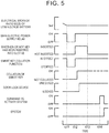
- FIG. 5 is an illustrative view showing an example of how the system of the automobile 20 is activated after the automobile 20 has been left unattended for a long time.
- the electric power supply ECU 80 turns off the main electric power supply relay 42. Then, the electric power supply ECU 80 (including the smart key collation function) is stopped.
- the main electric power supply relay 42 is turned on due to the electric power of the storage battery 92 of the smart key 90, and the drive ECU 32 and the electric power supply ECU 80 are activated. Then, the smart key collation function of the electric power supply ECU 80 becomes effective to collate the key-side ID and the vehicle-side ID with each other. When the result of collation is acceptable, the door lock device is caused to unlock the doors. After that, even when the user removes the smart key 90 from the key slot 60 (at a timing t13), the main electric power supply relay 42 is held on. When the user gets on the automobile and issues a command to activate the system (at a timing t14), the drive ECU 32 and the electric power supply ECU 80 activate the system.
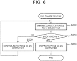
- FIG. 6 is a flowchart showing an exemplary key charge routine that is executed by the electric power supply ECU 80. This routine is executed when the smart key 90 is inserted into the key slot 70 and the system has been activated (when the subsidiary electric power supply relay 52 is on).
- the electric power supply ECU 80 first inputs an electrical storage ratio SOCk of the storage battery 92 of the smart key 90 (step S200), and compares the input electrical storage ratio SOCk of the storage battery 92 with a threshold SOCkref (step S210).
- a value computed based on a voltage or current on the key slot 70 side rather than on the key charge ECU 72 side, which has been detected by a voltage sensor (not shown) or a current sensor (not shown) is input as the electrical storage ratio SOCk of the storage battery 92.
- the threshold SOCkref is determined as the electrical storage ratio SOCk of the storage battery 92 in its fully charged state, and 90%, 95%, 100%, or the like is used as the threshold SOCkref.
- the key charge DC-DC converter 72 is controlled such that the electric power of the low voltage-side electric power line PL is stepped down and supplied to the smart key 90 (the storage battery 92) via the key slot 70 (step S220), and a return to step S200 is made. That is, the key slot 70 and the key charge DC-DC converter 72 function as an electric power feed unit that is configured to feed electric power to the smart key 90 (the storage battery 92).
- step S230 When the electrical storage ratio SOCk of the storage battery 92 becomes equal to or higher than the threshold SOCkref as a result of repeatedly carrying out the processing of steps S200 to S220 in this manner, the control of the key charge DC-DC converter 72 is stopped (step S230), and the present routine is ended.
- the storage battery 92 of the smart key 90 can be charged in this manner.
- the automobile 20 includes the key slot 60 (the positive electrode terminal 60a and the negative electrode terminal 60b) into which the smart key 90 is inserted and that is configured to receive, from the smart key 90, electric power for turning on the main electric power supply relay 42.
- the main electric power supply relay 42 is turned on due to the electric power of the storage battery 92 of the smart key 90, and the drive ECU 32 and the electric power supply ECU 80 are activated.
- the system can be activated. That is, even in the case where the automobile 20 has been left unattended for a long time, the system can be easily activated without requesting support from the operator or connecting the battery of the own vehicle to a battery of another vehicle (a rescue vehicle).
- the automobile 20 includes the key slot 70 (the positive electrode terminal 70a and the negative electrode terminal 70b) into which the smart key 90 is inserted and that is configured to feed electric power to the smart key 90.
- the key slot 70 the positive electrode terminal 70a and the negative electrode terminal 70b
- the smart key 90 is inserted in the key slot 70, it is possible to charge the smart key 90.
- the automobile 20 it is determined whether or not the automobile 20 has been left unattended for a long time, by comparing the electrical storage ratio SOCL of the low-voltage battery 40 and the threshold SOCLref with each other. Besides, this determination may be made by comparing a period for which the automobile 20 has been left unattended and a predetermined period (e.g., about several tens of days) with each other.
- a predetermined period e.g., about several tens of days
- a ratchet electromagnetic relay is used as the main electric power supply relay 42.
- a latching electromagnetic relay may be used as a main electric power supply relay 142.
- the automobile 120 shown in FIG. 7 includes the same hardware configuration as the automobile 20 shown in FIG. 1 , except in that the main electric power supply relay 142 is used instead of the main electric power supply relay 42. Accordingly, identical or similar components of the automobile 120 shown in FIG. 7 and the automobile 20 shown in FIG. 1 are denoted by the same reference symbols respectively, and the detailed description thereof will be omitted. Besides, those components of the automobile 120 shown in FIG. 7 which are located on a high voltage side with respect to the DC-DC converter 26 (the motor 22, the inverter 23, the high-voltage battery 24, the DC-DC converter 26, the high voltage-side electric power line PH, and the system main relay 28) are not depicted either.
- the DC-DC converter 26 the motor 22, the inverter 23, the high-voltage battery 24, the DC-DC converter 26, the high voltage-side electric power line PH, and the system main relay 28
- the main electric power supply relay 142 of the automobile 120 is configured as a latching electromagnetic relay, and includes coils 142a and 142b and an operation portion 142c.
- the coil 142a is connected at one end thereof to the electric power supply ECU 80 and the positive electrode terminal 60a of the key slot 60, and is grounded at the other end thereof to the vehicle body.
- the coil 142b is connected at one end thereof to the electric power supply ECU 80, and is grounded at the other end thereof to the vehicle body.
- the operation portion 142c connects the positive electrode terminal of the low-voltage battery 40 and the positive electrode line PLP of the low voltage-side electric power line PL to each other when the coil 142a shifts from its non-energized state to its energized state, holds the positive electrode terminal of the low-voltage battery 40 and the positive electrode line PLP of the low voltage-side electric power line PL connected to each other even when the coil 142a shifts from its energized state to its non-energized state afterward, disconnects the positive electrode terminal of the low-voltage battery 40 and the positive electrode line PLP of the low voltage-side electric power line PL from each other when the coil 142b shifts from its non-energized state to its energized state afterward, and holds the positive electrode terminal of the low-voltage battery 40 and the positive electrode line PLP of the low voltage-side electric power line PL disconnected from each other even when the coil 142b shifts from its energized state to its non-energized state afterward.
- the automobile 20 includes the key slot 70 and the key charge DC-DC converter 72, as the electric power feed unit that is configured to feed electric power to the smart key 90 (the storage battery 92).
- the key slot 70 and the key charge DC-DC converter 72 may not be provided.
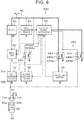
- the automobile 20 according to the embodiment is configured as shown in FIG. 1 , but may be configured as an automobile 220 according to a modification example of FIG. 8 .
- the automobile 220 shown in FIG. 8 includes the same hardware configuration as the automobile 20 shown in FIG. 1 , except in that the key slot 60 outside the vehicle cabin is not provided, that a main electric power supply relay 242 is used instead of the main electric power supply relay 42, and that the main electric power supply relay 242 and the key slot 70 inside the vehicle cabin are connected to each other. Accordingly, identical or similar components of the automobile 220 shown in FIG. 8 and the automobile 20 shown in FIG. 1 are denoted by the same reference symbols respectively, and the detailed description thereof will be omitted. Besides, those components of the automobile 220 shown in FIG.
- the main electric power supply relay 242 of the automobile 220 includes a first relay 243 and a second relay 244.
- the first relay 243 is configured as a ratchet electromagnetic relay, and connects and disconnects the positive electrode terminal of the low-voltage battery 40 and the positive electrode line PLP of the low voltage-side electric power line PL to and from each other by being turned on and off.
- This first relay 243 includes a coil 243a and an operation portion 243b.
- the coil 243a is connected at one end thereof to the electric power supply ECU 80, and is grounded at the other end thereof to the vehicle body.
- the operation portion 243b connects the positive electrode terminal of the low-voltage battery 40 and the positive electrode line PLP of the low voltage-side electric power line PL to each other when the coil 243a shifts from its non-energized state to its energized state, holds the positive electrode terminal of the low-voltage battery 40 and the positive electrode line PLP of the low voltage-side electric power line PL connected to each other even when the coil 243a shifts from its energized state to its non-energized state afterward, disconnects the positive electrode terminal of the low-voltage battery 40 and the positive electrode line PLP of the low voltage-side electric power line PL from each other when the coil 243a shifts from its non-energized state to its energized state afterward, and holds the positive electrode terminal of the low-voltage battery 40 and the positive electrode line PLP of the low voltage-side electric power line PL disconnected from each other even when the coil 243a shifts from its energized state to its non-energized state afterward.
- the second relay 244 is configured as a ratchet electromagnetic relay, and connects and disconnects the electric power supply ECU 80 and one end of the coil 243a (on the electric power supply ECU 80 side) to and from the positive electrode terminal 70a of the key slot 70 and the first positive electrode terminal 72a of the key charge DC-DC converter 72 by being turned on and off.
- This second relay 244 includes a coil 244a and an operation portion 244b.
- the coil 243a is connected at one end thereof to the electric power supply ECU 80, and is grounded at the other end thereof to the vehicle body.
- the operation portion 244b connects the electric power supply ECU 80 and one end of the coil 243a (on the electric power supply ECU 80 side) to the positive electrode terminal 70a of the key slot 70 and the second positive electrode terminal 72b of the key charge DC-DC converter 72 when the coil 244a shifts from its non-energized state to its energized state, holds the electric power supply ECU 80 and one end of the coil 243a connected to the positive electrode terminal 70a of the key slot 70 and the second positive electrode terminal 72b of the key charge DC-DC converter 72 even when the coil 244a shifts from its energized state to its non-energized state afterward, disconnects the electric power supply ECU 80 and one end of the coil 243a (on the electric power supply ECU 80 side) from the positive electrode terminal 70a of the key slot 70 and the second positive electrode terminal 72b of the key charge DC-DC converter 72 when the coil 244a shifts from its non-energized state to its energized state afterward, and holds the electric power supply ECU 80 and one end of the
- the electric power supply ECU 80 of the automobile 220 controls the changeover in the on and off state of the first relay 243 by shifting the coil 243a of the main electric power supply relay 242 from its non-energized state to its energized state, and controls the changeover in the on and off state of the second relay 244 by shifting the coil 244a from its non-energized state to its energized state.
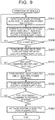
- FIG. 9 is an illustrative view for illustrating the flow of operation of the automobile 220 after the automobile 220 is parked thereof.
- the illustrative view of FIG. 9 is identical to FIG. 4 except in that the processing of steps S300 to S330 is performed instead of the processing of steps S110 to S130, and that the processing of steps S140 to S160 is not performed. Accordingly, like processing steps are denoted by like step numbers, and the detailed description thereof will be omitted.
- the first relay 243 of the main electric power supply relay 242 is on, and the second relay 244 thereof is off.
- the electric power supply ECU 80 turns on the second relay 244 of the main electric power supply relay 242, and turns off the first relay 243 thereof (step S300).
- Each of the first relay 243 and the second relay 244 is configured as a ratchet electromagnetic relay.
- the second relay 244 is turned on through the shifting of the coil 244a from its non-energized state to its energized state by the electric power supply ECU 80, and the first relay 243 is turned off through the shifting of the coil 243a from its non-energized state to its energized state by the electric power supply ECU 80.
- the electric power supply ECU 80 and one end of the coil 243a are connected to the positive electrode terminal 70a of the key slot 70 and the second positive electrode terminal 72b of the key charge DC-DC converter 72.
- the first relay 243 is turned off, the positive electrode terminal of the low-voltage battery 40 and the positive electrode line PLP of the low voltage-side electric power line PL are disconnected from each other, and electric power is stopped from being fed from the low-voltage battery 40 to the positive electrode line PLP of the low voltage-side electric power line PL, namely, from being fed to the DC-DC converter 26, the drive ECU 32, the first auxiliary device 44, the electric power supply ECU 80, and the like.
- the coils 243a and 244a are also rendered in their non-energized states, but the first relay 243 is held off, and the second relay 244 is held on.
- step S320 when the user mechanically unlocks the doors through the use of the smart key 90 and gets on the automobile, and the smart key 90 is inserted into the key slot 70 so that the positive electrode terminal 92a and the negative electrode terminal 92b of the smart key 90 come into contact with the positive electrode terminal 70a and the negative electrode terminal 70b of the key slot 70 respectively (step S310), the first relay 243 is turned on (step S320).
- the first relay 243 is turned on by applying the voltage of the storage battery 92 of the smart key 90 to the coil 243a of the first relay 243 to shift the coil 243a from its non-energized state to its energized state.
- the positive electrode terminal of the low-voltage battery 40 and the positive electrode line PLP of the low voltage-side electric power line PL are connected to each other, and electric power is fed from the low-voltage battery 40 to the positive electrode line PLP of the low voltage-side electric power line PL, namely, to the DC-DC converter 26, the drive ECU 32, the first auxiliary device 44, the electric power supply ECU 80, and the like.
- the drive ECU 32 and the electric power supply ECU 80 are activated.
- the electric power supply ECU 80 Upon being activated, the electric power supply ECU 80 turns off the second relay 244 of the main electric power supply relay 242 (step S330). Then, the processing of steps S170 and S180, which are similar to the flow of operation of the automobile 20 shown in FIG. 4 , is performed, and the flow of operation of the automobile 220 shown in FIG. 9 comes to an end.
- the second relay 244 is turned off through the shifting of the coil 244a from its non-energized state to its energized state by the electric power supply ECU 80.
- the electric power supply ECU 80 and one end of the coil 243a are disconnected from the positive electrode terminal 70a of the key slot 70 and the second positive electrode terminal 72b of the key charge DC-DC converter 72.
- the second relay 244 of the main electric power supply relay 242 is turned on before turning off the first relay 243 thereof.
- the first relay 243 of the main electric power supply relay 242 is turned off and the drive ECU 32, the electric power supply ECU 80, and the like is stopped, when the user inserts the smart key 90 into the key slot 70, the first relay 243 is turned on through the use of the electric power of the storage battery 92 provided in the smart key 90, and the drive ECU 32 and the electric power supply ECU 80 are activated.
- the system can be activated. That is, even in the case where the automobile 20 has been left unattended for a long time, the system can be easily activated without requesting support from the operator or connecting the battery of the own vehicle to a battery of another vehicle (a rescue vehicle).
- FIG. 10 is an illustrative view showing an example of how the system of the automobile 220 is activated after the automobile 220 has been left unattended for a long time.
- the electric power supply ECU 80 turns on the second relay 244 of the main electric power supply relay 242, and then turns off the first relay 243 thereof.
- the electric power supply ECU 80 (including the smart key collation function) is stopped.
- the first relay 243 is turned on due to the electric power of the storage battery 92 of the smart key 90, and the drive ECU 32 and the electric power supply ECU 80 are activated.
- the electric power supply ECU 80 turns off the second relay 244, and collates the key-side ID and the vehicle-side ID with each other through the smart key collation function.
- the drive ECU 32 and the electric power supply ECU 80 activate the system.
- the electric power supply ECU 80 executes the key charge routine of FIG. 6 , as is the case with the automobile 20 according to the embodiment.
- the smart key 90 can be charged.
- the second relay 244 of the main electric power supply relay 242 is off, and the electric power supply ECU 80 and one end of the coil 243a (on the electric power supply ECU 80 side) are disconnected from the positive electrode terminal 70a of the key slot 70 and the second positive electrode terminal 72b of the key charge DC-DC converter 72.
- a ratchet electromagnetic relay is used as each of the first relay 243 and the second relay 244 of the main electric power supply relay 242.
- a latching electromagnetic relay may be used instead. In this case, it is possible to reason in the same manner as in the case where the main electric power supply relay 42 of the automobile 20 shown in FIG. 1 is replaced with the main electric power supply relay 142 of the automobile 120 shown in FIG. 7 .
- the automobile 20 according to the embodiment is configured as an electric automobile or a hybrid automobile.
- the automobile 320 shown in FIG. 11 includes the same hardware configuration as the automobile 20 shown in FIG. 1 , except in that an engine 322, a starter 324, and an alternator 326 are provided instead of the motor 22, the inverter 23, the high-voltage battery 24, the DC-DC converter 26, the high voltage-side electric power line PH, and the system main relay 28 of the automobile 20 shown in FIG. 1 .
- identical or similar components of the automobile 320 shown in FIG. 11 and the automobile 20 shown in FIG. 1 are denoted by the same reference symbols respectively, and the detailed description thereof will be omitted.
- the engine 322 is configured as an internal combustion engine that outputs motive power using gasoline, light oil, or the like as fuel.
- the starter 324 is connected to a crankshaft of the engine 322 via a gear mechanism.
- a positive electrode terminal of the starter 324 is connected to the positive electrode line PLP of the low voltage-side electric power line PL, and a negative electrode terminal of the starter 324 is grounded to the vehicle body.
- the gear mechanism includes an engine-side gear that is attached to the crankshaft of the engine 322, a starter-side gear that is attached to a rotary shaft of the starter 324, and an actuator that realizes and cancels the meshing of the engine-side gear and the starter-side gear.
- a one-way clutch may be provided between the engine 322 and the starter 324.
- the alternator 326 is connected to the crankshaft of the engine 322 via the gear mechanism or a belt mechanism.
- a positive electrode terminal of the alternator 326 is connected to the positive electrode line PLP of the low voltage-side electric power line PL, and a negative electrode terminal of the alternator 326 is grounded to the vehicle body.
- signals from various sensors that detect states of the engine 322, the starter 324, the alternator 326, and the like are input to the drive ECU 32 via the input ports thereof respectively.
- Various control signals to the engine 322, the starter 324, the alternator 326, and the like are output from the drive ECU 32 via the output ports thereof respectively.
- the automobile 320 according to this modification example can also exert an effect similar to that of the automobile 20 according to the embodiment, by including the key slot 60 (the positive electrode terminal 60a and the negative electrode terminal 60b) and the key slot 70 (the positive electrode terminal 70a and the negative electrode terminal 70b).
- the drive ECU 32 controls the engine 322 and the starter 324, and starts up the engine 322.
- the automobile 320 according to this modification example is configured to include the engine 322, the starter 324, and the alternator 326 instead of the motor 22, the inverter 23, the high-voltage battery 24, the DC-DC converter 26, the high voltage-side electric power line PH, and the system main relay 28 of the automobile 20 shown in FIG. 1 .
- the automobile 320 may be configured to include the engine 322, the starter 324, and the alternator 326 instead of the motor 22 (not shown), the inverter 23 (not shown), the high-voltage battery 24 (not shown), the DC-DC converter 26 (not shown), the high voltage-side electric power line PH (not shown), and the system main relay 28 (not shown) of the automobiles 120 and 220 shown in FIGS. 7 and 8 respectively.
- Each of the automobiles 20, 120, and 320 according to the embodiment and the modification examples includes the key slot 60 that is provided outside the vehicle cabin and into which the smart key 90 is inserted, as the electric power reception unit that is configured to receive, from the smart key 90 (the storage battery 92), electric power for turning on the main electric power supply relay 42.
- the automobile 220 according to the modification example includes the key slot 70 that is provided inside the vehicle cabin and into which the smart key 90 is inserted, as the electric power reception unit that is configured to receive, from the smart key 90, electric power for turning on the electric power supply relay 242.
- the automobile 220 may have at least one of a placement portion that is provided inside the vehicle cabin and onto which the smart key 90 is placed, and a non-contact electric power reception portion that is configured to receive electric power from the smart key 90 in a non-contact manner, as the electric power reception unit that is configured to receive, from the smart key 90, electric power for turning on the main electric power supply relay 42 or the main electric power supply relay 242.
- the placement portion is provided around the driver seat as indicated by, for example, the region surrounded by the broken line in FIG. 3 .
- the non-contact electric power reception portion is provided around the door handle as indicated by, for example, the region surrounded by the broken line in FIG. 2 , or is provided around the driver seat as indicated by, for example, the region surrounded by the broken line in FIG. 3 .
- Each of the automobiles 20, 120, 220, and 320 uses the smart key 90 as a portable device that includes the storage battery 92 provided therein, that is portable, and that is configured to authenticate the user of the vehicle and feed electric power to the vehicle.
- a smartphone, a tablet terminal or the like may be used.
- a portable device that is configured to carry out at least one of the authentication of the user of the vehicle and the issuance of a command to activate the system of the vehicle may be used.
- the key slot 60 is an example of "the electric power reception unit”.
- the key slot 70 is an example of "the electric power feed unit” or "the electric power reception unit”.
- the low-voltage battery 40 is an example of "the in-vehicle electrical storage device”
- the system main relay 28, the drive ECU 32, the subsidiary electric power supply relay 52, and the electric power supply ECU 80 constitute an example of "the activation unit”
- the main electric power supply relay 42 is an example of "the relay”.
- the embodiment is an example for concretely illustrating the mode for carrying out the invention described in the section of means for solving the problem
- the corresponding relationship between the main elements of the embodiment and the main elements of the invention described in the section of means for solving the problem does not limit the elements of the invention described in the section of means for solving the problem. That is, the invention described in the section of means for solving the problem should be interpreted based on what is described in the section, and the embodiment is nothing more than a concrete example of the invention described in the section of means for solving the problem.
- the invention can be utilized in a vehicle manufacturing industry and the like.
- a vehicle includes an electric power reception unit that is configured to receive electric power that is required to activate a system of the vehicle, from a portable device that is portable, the portable device including an electrical storage device provided therein, and the portable device being configured to carry out at least one of authentication of a user of the vehicle and issuance of a command to activate the system.
Landscapes
- Engineering & Computer Science (AREA)
- Mechanical Engineering (AREA)
- Power Engineering (AREA)
- Transportation (AREA)
- Chemical & Material Sciences (AREA)
- Combustion & Propulsion (AREA)
- General Engineering & Computer Science (AREA)
- Electric Propulsion And Braking For Vehicles (AREA)
- Charge And Discharge Circuits For Batteries Or The Like (AREA)
- Lock And Its Accessories (AREA)
Abstract
Description
- The invention relates to a vehicle and a portable device.
- Conventionally, there has been proposed a vehicle that includes a battery that supplies electric power to an electric power supply ECU and various ECUs, and that is configured such that the electric power supply ECU has a control unit and an electric power supply cutoff circuit provided between the battery and the various ECUs (e.g., see Japanese Patent Application Publication No.
2003-70175 JP 2003-70175 A - In the case where the vehicle has been left unattended for a long time, even when the supply of electric power from the battery to the various ECUs is cut off as described above, the battery may become dead. When the battery becomes dead, the electric power of the battery cannot be used to activate a system. As a countermeasure against this, it is conceivable to further restrain the electric power of the battery from being consumed by cutting off the supply of electric power from the battery to the electric power supply ECU as well, with a view to restraining the battery from becoming dead. However, when the supply of electric power from the battery to the electric power supply ECU is cut off in the above-mentioned vehicle, there is no means for activating the electric power supply ECU afterward, so the system cannot be activated. On such occasions, there have been demands to enable easy activation of the system without requesting support from an operator or connecting the battery of the own vehicle to a battery of another vehicle (a rescue vehicle) through the use of a cable.
- A vehicle according to an aspect of the invention and a portable device according to another aspect of the invention make it possible to easily activate a system of the vehicle even in the case where the vehicle has been left unattended for a long time.
- The vehicle and the portable device according to the aspects of the invention have the following configurations.
- The vehicle according to the aspect of the invention includes an electric power reception unit that is configured to receive electric power that is required to activate a system of the vehicle, from a portable device that is portable, the portable device including an electrical storage device provided therein, and the portable device being configured to carry out at least one of authentication of a user of the vehicle and issuance of a command to activate the system.
- Owing to the aforementioned configuration, the system can be activated through the use of the electric power from the electrical storage device of the portable device. As a result, the system of the vehicle can be easily activated even in the case where the vehicle has been left unattended for a long time.
- In the vehicle according to the aforementioned aspect of the invention, the electric power reception unit may include at least one of an exterior insertion portion which is provided outside a vehicle cabin and into which the portable device is inserted, an interior insertion portion which is provided inside the vehicle cabin and into which the portable device is inserted, a placement portion that is provided inside the vehicle cabin and onto which the portable device is placed, and a non-contact electric power reception portion that is configured to receive the electric power from the portable device in a non-contact manner. Owing to the aforementioned configuration, when the portable device is inserted into the exterior insertion portion or the interior insertion portion or placed onto the placement portion, electric power can be received from the portable device, or electric power can be received from the portable device in a non-contact manner.
- Besides, in the vehicle according to the aforementioned aspect of the invention, the electric power reception unit may be configured to receive the electric power from the portable device and feed the electric power to the portable device. Besides, the vehicle may further include an electric power feed unit that is configured to feed the electric power to the portable device. In these cases, the electrical storage device of the portable device can be charged by feeding electric power from the vehicle to the portable device.
- Furthermore, the vehicle according to the aforementioned aspect of the invention may further include an in-vehicle electrical storage device, an activation unit that is configured to activate the system, and a relay that connects and disconnects the in-vehicle electrical storage device and the activation unit to and from each other by being turned on and off, and the electric power reception unit may be configured to receive, from the portable device, the electric power for turning on the relay. Owing to the aforementioned configuration, when the relay is supplied with the electric power of the electrical storage device of the portable device via the electric power reception unit and turned on, electric power can be fed from the in-vehicle electrical storage device to the activation unit, and the system can be activated. "The activation unit" may include pieces of equipment that are needed to activate the system, and a control device that controls the pieces of equipment.
- The portable device according to the aspect of the invention includes an electrical storage device. The portable device is portable, and is configured to carry out at least one of authentication of a user of a vehicle and issuance of a command to activate a system of the vehicle. The portable device is configured to feed electric power to the vehicle including an electric power reception unit that is configured to receive the electric power that is required to activate the system of the vehicle.
- In the portable device according to the aforementioned aspect of the invention, electric power can be fed to the vehicle including the electric power reception unit that is configured to receive the electric power that is required to activate the system, so the system can be activated through the use of the electric power from the electrical storage device of the portable device. As a result, even in the case where the vehicle has been left unattended for a long time, the system of the vehicle can be easily activated.
- Features, advantages, and technical and industrial significance of an exemplary embodiment of the invention will be described below with reference to the accompanying drawings, in which like numerals denote like elements, and wherein:
-
FIG. 1 is a configuration view showing the outline of the configurations of anautomobile 20 and asmart key 90 according to the embodiment of the invention; -
FIG. 2 is an illustrative view showing a position where akey slot 60 is provided; -
FIG. 3 is an illustrative view showing a position where akey slot 70 is provided; -
FIG. 4 is an illustrative view for illustrating the flow of operation of theautomobile 20 after theautomobile 20 is parked thereof; -
FIG. 5 is an illustrative view showing an example of how a system of theautomobile 20 is activated after theautomobile 20 has been left unattended for a long time; -
FIG. 6 is a flowchart showing an exemplary key charge routine that is executed by an electricpower supply ECU 80; -
FIG. 7 is a configuration view showing the outline of the configuration of anautomobile 120 according to a modification example; -
FIG. 8 is a configuration view showing the outline of the configuration of anautomobile 220 according to another modification example; -
FIG. 9 is an illustrative view for illustrating the flow of operation of theautomobile 220 after theautomobile 220 is parked thereof; -
FIG. 10 is an illustrative view showing an example of how a system of theautomobile 220 is activated after theautomobile 220 has been left unattended for a long time; and -
FIG. 11 is a configuration view showing the outline of the configuration of anautomobile 320 according to still another modification example. - Next, a mode for carrying out the invention will be described through the use of the embodiment thereof.
-
FIG. 1 is a configuration view showing the outline of the configurations of an automobile (an example of a vehicle) 20 and asmart key 90 according to the embodiment of the invention. Theautomobile 20 according to the embodiment is configured as an electric automobile or a hybrid automobile. As shown in the drawing, theautomobile 20 includes amotor 22, aninverter 23, a high-voltage battery 24, a DC-DC converter 26, a systemmain relay 28, a drive electronic control unit (hereinafter referred to as "a drive ECU") 32, a low-voltage battery 40 as an in-vehicle electrical storage device, a main electricpower supply relay 42, a firstauxiliary device 44, a secondauxiliary device 50, a subsidiary electricpower supply relay 52,key slots DC converter 72, and an electric power supply electronic control unit (hereinafter referred to as "an electric power supply ECU") 80. - The
motor 22 is configured as, for example, a synchronous generator-motor, and outputs motive power for running. Theinverter 23 is used to drive themotor 22, and is connected to a positive electrode line PHP and a negative electrode line PHN of a high voltage-side electric power line PH. Themotor 22 is rotationally driven through the performance of switching control of a plurality of switching elements of theinverter 23 by thedrive ECU 32. The high-voltage battery 24 is configured as a lithium-ion secondary battery or a nickel hydride secondary battery with a rated voltage of about several hundreds of V. - A first positive electrode terminal and a first negative electrode terminal of the DC-
DC converter 26 are connected to the positive electrode line PHP and the negative electrode line PHN of the high voltage-side electric power line PH respectively. A second positive electrode terminal of the DC-DC converter 26 is connected to a positive electrode line PLP of a low voltage-side electric power line PL. A second negative electrode terminal of the DC-DC converter 26 is grounded to a vehicle body that is made of metal. In the embodiment, the vehicle body is used as a negative electrode line PLN of the low voltage-side electric power line PL. Accordingly, "being grounded to the vehicle body" is synonymous with "being connected to the negative electrode line PLN of the low voltage-side electric power line PL". This DC-DC converter 26 steps down the electric power of the high voltage-side electric power line PH and supplies the low voltage-side electric power line PL therewith. - The system
main relay 28 includes apositive electrode relay 29 and anegative electrode relay 30. Thepositive electrode relay 29 is configured as a normal open-type electromagnetic relay, and connects and disconnects a positive electrode terminal of the high-voltage battery 24 and the positive electrode line PHP of the high voltage-side electric power line PH to and from each other by being turned on and off. Thispositive electrode relay 29 includes acoil 29a and anoperation portion 29b. Thecoil 29a is connected at one end thereof to thedrive ECU 32, and is grounded at the other end thereof to the vehicle body. Theoperation portion 29b connects the positive electrode terminal of the high-voltage battery 24 and the positive electrode line PHP of the high voltage-side electric power line PH to each other when thecoil 29a is in its energized state, and disconnects the positive electrode terminal of the high-voltage battery 24 and the positive electrode line PHP of the high voltage-side electric power line PH from each other when thecoil 29a is in its non-energized state. - The
negative electrode relay 30 is configured as a normal open-type electromagnetic relay, and connects and disconnects a negative electrode terminal of the high-voltage battery 24 and the negative electrode line PHN of the high voltage-side electric power line PH to and from each other by being turned on and off. Thisnegative electrode relay 30 includes acoil 30a and anoperation portion 30b. Thecoil 30a is connected at one end thereof to thedrive ECU 32, and is grounded at the other end thereof to the vehicle body. Theoperation portion 30b connects the negative electrode terminal of the high-voltage battery 24 and the negative electrode line PHN of the high voltage-side electric power line PH to each other when thecoil 30a is in its energized state, and disconnects the negative electrode terminal of the high-voltage battery 24 and the negative electrode line PHN of the high voltage-side electric power line PH from each other when thecoil 30a is in its non-energized state. - Although not shown in the drawing, the
drive ECU 32 is configured as a microprocessor that is mainly constituted of a CPU. In addition to the CPU, thedrive ECU 32 includes a ROM that stores a processing program, a RAM that temporarily stores data, input and output ports, and a communication port. A positive electrode terminal of thisdrive ECU 32 is connected to the positive electrode line PLP of the low voltage-side electric power line PL, and a negative electrode terminal of thisdrive ECU 32 is grounded to the vehicle body. Thedrive ECU 32 operates upon being fed with electric power from the low voltage-side electric power line PL. - Signals from a sensor that detects a state (e.g., a rotational position of a rotor or a phase current) of the
motor 22, a sensor that detects a state (e.g., a voltage or a current) of the high-voltage battery 24, a sensor that detects a state (e.g., a voltage of the high voltage-side electric power line PH or a voltage of the low voltage-side electric power line PL) of the DC-DC converter 26, and the like are input to thedrive ECU 32 via the input ports thereof respectively. Various control signals to theinverter 23, the DC-DC converter 26, and the like are output from thedrive ECU 32 via the output ports thereof respectively. Thedrive ECU 32 controls the on and off states of thepositive electrode relay 29 and thenegative electrode relay 30 by rendering thecoils - The
drive ECU 32 computes an electrical storage ratio SOCH of the high-voltage battery 24 based on an input and output current of the high-voltage battery 24 from a current sensor. Besides, thedrive ECU 32 is connected to an electricpower supply ECU 80 via the communication port. - The low-
voltage battery 40 is configured as a lead storage battery with a rated voltage of, for example, 12 V. A negative electrode terminal of the low-voltage battery 40 is grounded to the vehicle body. The main electricpower supply relay 42 is configured as a ratchet electromagnetic relay that needs a current to be turned on and off and that does not need any current to be held on and off. The main electricpower supply relay 42 connects and disconnects the positive electrode terminal of the low-voltage battery 40 and the positive electrode line PLP of the low voltage-side electric power line PL to and from each other by being turned on and off. This main electricpower supply relay 42 includes acoil 42a and anoperation portion 42b. Thecoil 42a is connected at one end thereof to the electricpower supply ECU 80, and is grounded at the other end thereof to the vehicle body. Theoperation portion 42b connects the positive electrode terminal of the low-voltage battery 40 and the positive electrode line PLP of the low voltage-side electric power line PL to each other when thecoil 42a shifts from its non-energized state to its energized state, holds the positive electrode terminal of the low-voltage battery 40 and the positive electrode line PLP of the low voltage-side electric power line PL connected to each other even when thecoil 42a shifts from its energized state to its non-energized state afterward, disconnects the positive electrode terminal of the low-voltage battery 40 and the positive electrode line PLP of the low voltage-side electric power line PL from each other when thecoil 42a shifts from its non-energized state to its energized state afterward, and holds the positive electrode terminal of the low-voltage battery 40 and the positive electrode line PLP of the low voltage-side electric power line PL disconnected from each other even when thecoil 42a shifts from its energized state to its non-energized state. That is, the main electricpower supply relay 42 is turned on or off every time thecoil 42a shifts from its non-energized state to its energized state. - A positive electrode terminal of the first
auxiliary device 44 is connected to the positive electrode line PLP of the low voltage-side electric power line PL, and a negative electrode terminal of the firstauxiliary device 44 is grounded to the vehicle body. For example, an auxiliary device concerning protection against theft and security of the automobile 20 (e.g., a horn, a hazard flasher, or the like), a door lock device that locks and unlocks doors of theautomobile 20, or the like can be mentioned as the firstauxiliary device 44. A negative electrode terminal of the secondauxiliary device 50 is grounded to the vehicle body. For example, an audio system, a power window, a navigation device, or the like can be mentioned as the secondauxiliary device 50. - The subsidiary electric
power supply relay 52 is configured as a normal open-type electromagnetic relay, and connects and disconnects a positive electrode terminal of the secondauxiliary device 50 and a firstpositive electrode terminal 72a of the key charge DC-DC converter 72 to and from the positive electrode line PLP of the low voltage-side electric power line PL by being turned on and off. This subsidiary electricpower supply relay 52 includes acoil 52a and anoperation portion 52b. Thecoil 52a is connected at one end thereof to the electricpower supply ECU 80, and is grounded at the other end thereof to the vehicle body. Theoperation portion 52b connects the positive electrode terminal of the secondauxiliary device 50 and the firstpositive electrode terminal 72a of the key charge DC-DC converter 72 to the positive electrode line PLP of the low voltage-side electric power line PL when thecoil 52a is in its energized state, and disconnects the positive electrode terminal of the secondauxiliary device 50 and the positive electrode line PLP of the low voltage-side electric power line PL from each other when thecoil 52a is in its non-energized state. - The
key slot 60 is provided outside a vehicle cabin, and is configured such that thesmart key 90 is inserted thereinto. Apositive electrode terminal 60a and anegative electrode terminal 60b of thekey slot 60 are exposed. Thepositive electrode terminal 60a is connected to one end of thecoil 42a of the main electricpower supply relay 42 and the electricpower supply ECU 80, and thenegative electrode terminal 60b is grounded to the vehicle body.FIG. 2 is an illustrative view showing a position where thekey slot 60 is provided. Thekey slot 60 is provided around a door handle as indicated by, for example, a region surrounded by a broken line inFIG. 2 . - The
key slot 70 is provided inside the vehicle cabin, and is configured such that thesmart key 90 is inserted thereinto. Apositive electrode terminal 70a and anegative electrode terminal 70b of thekey slot 70 are exposed. Thepositive electrode terminal 70a is connected to the key charge DC-DC converter 72, and thenegative electrode terminal 70b is grounded to the vehicle body.FIG. 3 is an illustrative view showing a position where thekey slot 70 is provided. Thekey slot 70 is provided around a driver seat as indicated by, for example, a region surrounded by a broken line inFIG. 3 . - The description of the
automobile 20 will now be temporarily stopped, and thesmart key 90 will be described. Thesmart key 90 includes astorage battery 92 as an electrical storage device provided therein, and apositive electrode terminal 92a and anegative electrode terminal 92b from thestorage battery 92 are exposed. Thestorage battery 92 is configured as, for example, a lithium-ion secondary battery with a rated voltage of several V. When thissmart key 90 is inserted into thekey slots positive electrode terminal 92a and thenegative electrode terminal 92b of thesmart key 90 come into contact with thepositive electrode terminals negative electrode terminals key slots automobile 20 and thesmart key 90 are electrically connected to each other. An ID corresponding to theautomobile 20 is stored in thesmart key 90. Besides, the smart key 90 can communicate with the electricpower supply ECU 80 of theautomobile 20 in a wireless manner. - The description of the
automobile 20 will be resumed. The firstpositive electrode terminal 72a of the key charge DC-DC converter 72 as well as the positive electrode terminal of the secondauxiliary device 50 is connected to the positive electrode line PLP of the low voltage-side electric power line PL via the subsidiary electric power supply relay 52 (theoperation portion 52b), a secondpositive electrode terminal 72b of the key charge DC-DC converter 72 is connected to thepositive electrode terminal 70a of thekey slot 70, and a negative electrode terminal of the key charge DC-DC converter 72 is grounded to the vehicle body. This key charge DC-DC converter 72 steps down the electric power of the low voltage-side electric power line PL, and supplies thekey slot 70 therewith when the subsidiary electricpower supply relay 52 is on. - Although not shown in the drawing, the electric
power supply ECU 80 is configured as a microprocessor that is mainly constituted of a CPU. In addition to the CPU, the electricpower supply ECU 80 includes a ROM that stores a processing program, a RAM that temporarily stores data, input and output ports, and a communication port. A positive electrode terminal of this electricpower supply ECU 80 is connected to the positive electrode line PLP of the low voltage-side electric power line PL, and a negative electrode terminal of this electricpower supply ECU 80 is grounded to the vehicle body. The electricpower supply ECU 80 operates upon being fed with electric power from the low voltage-side electric power line PL. A vehicle-side ID for authenticating a user is stored in the ROM of the electricpower supply ECU 80. - Signals from a sensor that detects a state (e.g., a voltage or a current) of the low-
voltage battery 40, a sensor that detects a state (e.g., a voltage or a current) of the firstauxiliary device 44, a sensor that detects a state (e.g., a voltage or a current) of the secondauxiliary device 50, a sensor that detects a state (e.g., a voltage on the secondauxiliary device 50 side, a voltage on thekey slot 70 side, or a current on thekey slot 70 side) of the key charge DC-DC converter 72, and the like are input to the electricpower supply ECU 80 via the input ports thereof respectively. Various control signals to the firstauxiliary device 44, the secondauxiliary device 50, the key charge DC-DC converter 72, and the like are output from the electricpower supply ECU 80 via the output ports thereof respectively. The electricpower supply ECU 80 controls the changeover in the on and off state of the main electricpower supply relay 42 by shifting thecoil 42a from its non-energized state to its energized state. Besides, the electricpower supply ECU 80 controls the on and off state of the subsidiary electricpower supply relay 52 by rendering thecoil 52a in its energized state or its non-energized state. - The electric
power supply ECU 80 computes the electrical storage ratio SOCL of the low-voltage battery 40 based on an input and output current of the low-voltage battery 40 from the current sensor. Besides, as described above, the electricpower supply ECU 80 is connected to thedrive ECU 32 via the communication port. Furthermore, thedrive ECU 32 can communicate with the smart key 90 in a wireless manner, and authenticates the user by collating a key-side ID from thesmart key 90 and the vehicle-side ID stored in the ROM of the electricpower supply ECU 80 with each other. This function will be referred to hereinafter as a "smart key collation function". - Next, the operation of the
automobile 20 according to the embodiment thus configured, especially the operation of theautomobile 20 that includes been parked and left unattended for a long time will be described.FIG. 4 is an illustrative view for illustrating the flow of the operation of theautomobile 20 after theautomobile 20 is parked thereof. - In the flow of the operation of the
automobile 20 inFIG. 4 , the electricpower supply ECU 80 first inputs the electrical storage ratio SOCL of the low-voltage battery 40 (step S100), and compares the input electrical storage ratio SOCL of the low-voltage battery 40 with the threshold SOCLref (steps S102 and S104). It should be noted herein that a value computed based on the input and output current of the low-voltage battery 40 from the current sensor is input as the electrical storage ratio SOCL of the low-voltage battery 40. A process of comparing the electrical storage ratio SOCL of the low-voltage battery 40 with the threshold SOCLref is a process of determining whether or not theautomobile 20 has been left unattended for a long time. For example, 20%, 25%, 30%, or the like is used as the threshold SOCLref. If the electrical storage ratio SOCL of the low-voltage battery 40 is higher than the threshold SOCLref, a return to step S100 is made. - If the electrical storage ratio SOCL of the low-
voltage battery 40 is equal to or lower than the threshold SOCLref in steps S102 and S104, the electricpower supply ECU 80 turns off the main electric power supply relay 42 (step S110). The main electricpower supply relay 42 is configured as a ratchet electromagnetic relay. Therefore, the main electricpower supply relay 42 is turned off through the shifting of thecoil 42a from its non-energized state to its energized state by the electricpower supply ECU 80. - When the main electric
power supply relay 42 is thus turned off, the positive electrode terminal of the low-voltage battery 40 and the positive electrode line PLP of the low voltage-side electric power line PL are disconnected from each other, and electric power is stopped from being fed from the low-voltage battery 40 to the positive electrode line PLP of the low voltage-side electric power line PL, namely, from being fed to the DC-DC converter 26, thedrive ECU 32, the firstauxiliary device 44, the electricpower supply ECU 80, and the like. By stopping electric power from being fed to the electricpower supply ECU 80, thecoil 42a is also rendered in its non-energized state, but the main electricpower supply relay 42 is held off. - After that, when the
smart key 90 is inserted into thekey slot 60 provided outside the vehicle cabin of the automobile 20 (e.g., in the door handle or the like) and thepositive electrode terminal 92a and thenegative electrode terminal 92b of thesmart key 90 come into contact with thepositive electrode terminal 60a and thenegative electrode terminal 60b of thekey slot 60 respectively (step S120), the main electricpower supply relay 42 is turned on (step S130). The main electricpower supply relay 42 is turned on by applying a voltage of thestorage battery 92 of the smart key 90 to thecoil 42a to shift thecoil 42a from its non-energized state to its energized state. That is, thekey slot 60 functions as an electric power reception unit that is configured to receive, from the smart key 90 (the storage battery 92), electric power for turning on the main electricpower supply relay 42. - When the main electric
power supply relay 42 is thus turned on, the positive electrode terminal of the low-voltage battery 40 and the positive electrode line PLP of the low voltage-side electric power line PL are connected to each other, and electric power is fed from the low-voltage battery 40 to the positive electrode line PLP of the low voltage-side electric power line PL, namely, to the DC-DC converter 26, thedrive ECU 32, the firstauxiliary device 44, the electricpower supply ECU 80, and the like. Thus, thedrive ECU 32 and the electricpower supply ECU 80 are activated. Incidentally, the main electricpower supply relay 42 is held on even when the user removes the smart key 90 from thekey slot 60 and thecoil 42a is rendered in its non-energized state. - When the
drive ECU 32 and the electricpower supply ECU 80 are activated, the smart key collation function of the electricpower supply ECU 80 becomes effective. By communicating with thesmart key 90, the electricpower supply ECU 80 collates the key-side ID from thesmart key 90 and the vehicle-side ID stored in the ROM of the electricpower supply ECU 80 with each other (steps S140 and S142). Then, if the result of collation shows that the key-side ID from thesmart key 90 and the vehicle-side ID stored in the ROM of the electricpower supply ECU 80 do not coincide with each other, the electricpower supply ECU 80 turns off the main electric power supply relay 42 (step S150), and the flow of the operation of theautomobile 20 inFIG. 4 comes to an end. - If the result of collation in steps S140 and S142 shows that the key-side ID from the
smart key 90 and the vehicle-side ID stored in the ROM of the electricpower supply ECU 80 coincide with each other, the electricpower supply ECU 80 causes the door lock device included in the firstauxiliary device 44 of theautomobile 20 to unlock the doors (step S160). Then, the electricpower supply ECU 80 stands by until the user gets on the automobile and issues a command to activate the system (step S170). The command to activate the system is issued through, for example, the operation of a start switch (not shown) by the user. - When the command to activate the system is issued in step S170, the electric
power supply ECU 80 activates the system (step S180), and the flow of the operation of theautomobile 20 inFIG. 4 comes to an end. In activating the system, for example, the electricpower supply ECU 80 turns on the subsidiary electricpower supply relay 52, and thedrive ECU 32 turns on the system main relay 28 (thepositive electrode relay 29 and the negative electrode relay 30). - When the activation of the system is thus completed, the DC-
DC converter 26 is driven by thedrive ECU 32, and the electric power of the high voltage-side electric power line PH is stepped down and supplied to the low voltage-side electric power line PL. Thus, the low-voltage battery 40 is charged. - In the embodiment, the key slot 60 (the
positive electrode terminal 60a and thenegative electrode terminal 60b) is provided. Thus, even in the case where thedrive ECU 32, the electricpower supply ECU 80, and the like are stopped by turning off the main electricpower supply relay 42, when the user inserts the smart key 90 into thekey slot 60, the main electricpower supply relay 42 is turned on through the use of the electric power of thestorage battery 92 provided in thesmart key 90, and thedrive ECU 32 and the electricpower supply ECU 80 are activated. Thus, the system can be activated. That is, even in the case where theautomobile 20 has been left unattended for a long time, the system can be easily activated without requesting support from an operator or connecting the battery of the own vehicle to a battery of another vehicle (a rescue vehicle). -
FIG. 5 is an illustrative view showing an example of how the system of theautomobile 20 is activated after theautomobile 20 has been left unattended for a long time. As shown in the drawing, when the electrical storage ratio SOCL of the low-voltage battery 40 becomes equal to or lower than the threshold SOCLref after theautomobile 20 has been left unattended for a long time (at a timing t11), the electricpower supply ECU 80 turns off the main electricpower supply relay 42. Then, the electric power supply ECU 80 (including the smart key collation function) is stopped. After that, when thesmart key 90 is inserted into thekey slot 60 outside the vehicle cabin (at a timing t12), the main electricpower supply relay 42 is turned on due to the electric power of thestorage battery 92 of thesmart key 90, and thedrive ECU 32 and the electricpower supply ECU 80 are activated. Then, the smart key collation function of the electricpower supply ECU 80 becomes effective to collate the key-side ID and the vehicle-side ID with each other. When the result of collation is acceptable, the door lock device is caused to unlock the doors. After that, even when the user removes the smart key 90 from the key slot 60 (at a timing t13), the main electricpower supply relay 42 is held on. When the user gets on the automobile and issues a command to activate the system (at a timing t14), thedrive ECU 32 and the electricpower supply ECU 80 activate the system. - Next, the operation at the time when the
smart key 90 is inserted in thekey slot 70 inside the vehicle cabin and thepositive electrode terminal 92a and thenegative electrode terminal 92b of thesmart key 90 are in contact with thepositive electrode terminal 70a and thenegative electrode terminal 70b of thekey slot 70 respectively (when this contact is detected by a sensor (not shown)) will be described.FIG. 6 is a flowchart showing an exemplary key charge routine that is executed by the electricpower supply ECU 80. This routine is executed when thesmart key 90 is inserted into thekey slot 70 and the system has been activated (when the subsidiary electricpower supply relay 52 is on). - When the key charge routine of
FIG. 6 is executed, the electricpower supply ECU 80 first inputs an electrical storage ratio SOCk of thestorage battery 92 of the smart key 90 (step S200), and compares the input electrical storage ratio SOCk of thestorage battery 92 with a threshold SOCkref (step S210). It should be noted herein that a value computed based on a voltage or current on thekey slot 70 side rather than on thekey charge ECU 72 side, which has been detected by a voltage sensor (not shown) or a current sensor (not shown), is input as the electrical storage ratio SOCk of thestorage battery 92. The threshold SOCkref is determined as the electrical storage ratio SOCk of thestorage battery 92 in its fully charged state, and 90%, 95%, 100%, or the like is used as the threshold SOCkref. - If the electrical storage ratio SOCk of the
storage battery 92 is lower than the threshold SOCkref, the key charge DC-DC converter 72 is controlled such that the electric power of the low voltage-side electric power line PL is stepped down and supplied to the smart key 90 (the storage battery 92) via the key slot 70 (step S220), and a return to step S200 is made. That is, thekey slot 70 and the key charge DC-DC converter 72 function as an electric power feed unit that is configured to feed electric power to the smart key 90 (the storage battery 92). - When the electrical storage ratio SOCk of the
storage battery 92 becomes equal to or higher than the threshold SOCkref as a result of repeatedly carrying out the processing of steps S200 to S220 in this manner, the control of the key charge DC-DC converter 72 is stopped (step S230), and the present routine is ended. Thestorage battery 92 of the smart key 90 can be charged in this manner. - The
automobile 20 according to the embodiment described above includes the key slot 60 (thepositive electrode terminal 60a and thenegative electrode terminal 60b) into which thesmart key 90 is inserted and that is configured to receive, from thesmart key 90, electric power for turning on the main electricpower supply relay 42. Thus, when thesmart key 90 is inserted into thekey slot 60, the main electricpower supply relay 42 is turned on due to the electric power of thestorage battery 92 of thesmart key 90, and thedrive ECU 32 and the electricpower supply ECU 80 are activated. Thus, the system can be activated. That is, even in the case where theautomobile 20 has been left unattended for a long time, the system can be easily activated without requesting support from the operator or connecting the battery of the own vehicle to a battery of another vehicle (a rescue vehicle). - Besides, the
automobile 20 according to the embodiment includes the key slot 70 (thepositive electrode terminal 70a and thenegative electrode terminal 70b) into which thesmart key 90 is inserted and that is configured to feed electric power to thesmart key 90. Thus, when thesmart key 90 is inserted in thekey slot 70, it is possible to charge thesmart key 90. - In the
automobile 20 according to the embodiment, it is determined whether or not theautomobile 20 has been left unattended for a long time, by comparing the electrical storage ratio SOCL of the low-voltage battery 40 and the threshold SOCLref with each other. Besides, this determination may be made by comparing a period for which theautomobile 20 has been left unattended and a predetermined period (e.g., about several tens of days) with each other. - In the
automobile 20 according to the embodiment, a ratchet electromagnetic relay is used as the main electricpower supply relay 42. Besides, as is apparent from anautomobile 120 according to a modification example ofFIG. 7 , a latching electromagnetic relay may be used as a main electricpower supply relay 142. - The
automobile 120 shown inFIG. 7 includes the same hardware configuration as theautomobile 20 shown inFIG. 1 , except in that the main electricpower supply relay 142 is used instead of the main electricpower supply relay 42. Accordingly, identical or similar components of theautomobile 120 shown inFIG. 7 and theautomobile 20 shown inFIG. 1 are denoted by the same reference symbols respectively, and the detailed description thereof will be omitted. Besides, those components of theautomobile 120 shown inFIG. 7 which are located on a high voltage side with respect to the DC-DC converter 26 (themotor 22, theinverter 23, the high-voltage battery 24, the DC-DC converter 26, the high voltage-side electric power line PH, and the system main relay 28) are not depicted either. - The main electric
power supply relay 142 of theautomobile 120 is configured as a latching electromagnetic relay, and includescoils operation portion 142c. Thecoil 142a is connected at one end thereof to the electricpower supply ECU 80 and thepositive electrode terminal 60a of thekey slot 60, and is grounded at the other end thereof to the vehicle body. Thecoil 142b is connected at one end thereof to the electricpower supply ECU 80, and is grounded at the other end thereof to the vehicle body. Theoperation portion 142c connects the positive electrode terminal of the low-voltage battery 40 and the positive electrode line PLP of the low voltage-side electric power line PL to each other when thecoil 142a shifts from its non-energized state to its energized state, holds the positive electrode terminal of the low-voltage battery 40 and the positive electrode line PLP of the low voltage-side electric power line PL connected to each other even when thecoil 142a shifts from its energized state to its non-energized state afterward, disconnects the positive electrode terminal of the low-voltage battery 40 and the positive electrode line PLP of the low voltage-side electric power line PL from each other when thecoil 142b shifts from its non-energized state to its energized state afterward, and holds the positive electrode terminal of the low-voltage battery 40 and the positive electrode line PLP of the low voltage-side electric power line PL disconnected from each other even when thecoil 142b shifts from its energized state to its non-energized state afterward. The electricpower supply ECU 80 of theautomobile 120 controls the changeover in the on and off state of the main electricpower supply relay 42 by selectively shifting each of thecoils - The
automobile 20 according to the embodiment includes thekey slot 70 and the key charge DC-DC converter 72, as the electric power feed unit that is configured to feed electric power to the smart key 90 (the storage battery 92). However, thekey slot 70 and the key charge DC-DC converter 72 may not be provided. - The
automobile 20 according to the embodiment is configured as shown inFIG. 1 , but may be configured as anautomobile 220 according to a modification example ofFIG. 8 . Theautomobile 220 shown inFIG. 8 includes the same hardware configuration as theautomobile 20 shown inFIG. 1 , except in that thekey slot 60 outside the vehicle cabin is not provided, that a main electricpower supply relay 242 is used instead of the main electricpower supply relay 42, and that the main electricpower supply relay 242 and thekey slot 70 inside the vehicle cabin are connected to each other. Accordingly, identical or similar components of theautomobile 220 shown inFIG. 8 and theautomobile 20 shown inFIG. 1 are denoted by the same reference symbols respectively, and the detailed description thereof will be omitted. Besides, those components of theautomobile 220 shown inFIG. 8 which are located on the high voltage side with respect to the DC-DC converter 26 (themotor 22, theinverter 23, the high-voltage battery 24, the DC-DC converter 26, the high voltage-side electric power line PH, and the system main relay 28) are not depicted either. - The main electric
power supply relay 242 of theautomobile 220 includes afirst relay 243 and asecond relay 244. Thefirst relay 243 is configured as a ratchet electromagnetic relay, and connects and disconnects the positive electrode terminal of the low-voltage battery 40 and the positive electrode line PLP of the low voltage-side electric power line PL to and from each other by being turned on and off. Thisfirst relay 243 includes acoil 243a and anoperation portion 243b. Thecoil 243a is connected at one end thereof to the electricpower supply ECU 80, and is grounded at the other end thereof to the vehicle body. Theoperation portion 243b connects the positive electrode terminal of the low-voltage battery 40 and the positive electrode line PLP of the low voltage-side electric power line PL to each other when thecoil 243a shifts from its non-energized state to its energized state, holds the positive electrode terminal of the low-voltage battery 40 and the positive electrode line PLP of the low voltage-side electric power line PL connected to each other even when thecoil 243a shifts from its energized state to its non-energized state afterward, disconnects the positive electrode terminal of the low-voltage battery 40 and the positive electrode line PLP of the low voltage-side electric power line PL from each other when thecoil 243a shifts from its non-energized state to its energized state afterward, and holds the positive electrode terminal of the low-voltage battery 40 and the positive electrode line PLP of the low voltage-side electric power line PL disconnected from each other even when thecoil 243a shifts from its energized state to its non-energized state afterward. - The
second relay 244 is configured as a ratchet electromagnetic relay, and connects and disconnects the electricpower supply ECU 80 and one end of thecoil 243a (on the electricpower supply ECU 80 side) to and from thepositive electrode terminal 70a of thekey slot 70 and the firstpositive electrode terminal 72a of the key charge DC-DC converter 72 by being turned on and off. Thissecond relay 244 includes acoil 244a and anoperation portion 244b. Thecoil 243a is connected at one end thereof to the electricpower supply ECU 80, and is grounded at the other end thereof to the vehicle body. The operation portion 244b connects the electric power supply ECU 80 and one end of the coil 243a (on the electric power supply ECU 80 side) to the positive electrode terminal 70a of the key slot 70 and the second positive electrode terminal 72b of the key charge DC-DC converter 72 when the coil 244a shifts from its non-energized state to its energized state, holds the electric power supply ECU 80 and one end of the coil 243a connected to the positive electrode terminal 70a of the key slot 70 and the second positive electrode terminal 72b of the key charge DC-DC converter 72 even when the coil 244a shifts from its energized state to its non-energized state afterward, disconnects the electric power supply ECU 80 and one end of the coil 243a (on the electric power supply ECU 80 side) from the positive electrode terminal 70a of the key slot 70 and the second positive electrode terminal 72b of the key charge DC-DC converter 72 when the coil 244a shifts from its non-energized state to its energized state afterward, and holds the electric power supply ECU 80 and one end of the coil 243a disconnected from the positive electrode terminal 70a of the key slot 70 and the second positive electrode terminal 72b of the key charge DC-DC converter 72 even when the coil 244a shifts from its energized state to its non-energized state afterward. - The electric
power supply ECU 80 of theautomobile 220 controls the changeover in the on and off state of thefirst relay 243 by shifting thecoil 243a of the main electricpower supply relay 242 from its non-energized state to its energized state, and controls the changeover in the on and off state of thesecond relay 244 by shifting thecoil 244a from its non-energized state to its energized state. - Next, the operation of the
automobile 220 according to this modification example thus configured, especially the operation of theautomobile 220 that has been parked and left unattended for a long time will be described.FIG. 9 is an illustrative view for illustrating the flow of operation of theautomobile 220 after theautomobile 220 is parked thereof. The illustrative view ofFIG. 9 is identical toFIG. 4 except in that the processing of steps S300 to S330 is performed instead of the processing of steps S110 to S130, and that the processing of steps S140 to S160 is not performed. Accordingly, like processing steps are denoted by like step numbers, and the detailed description thereof will be omitted. Incidentally, at the beginning of the flow of operation of theautomobile 220 shown inFIG. 9 , thefirst relay 243 of the main electricpower supply relay 242 is on, and thesecond relay 244 thereof is off. - In the flow of operation of the
automobile 220 shown inFIG. 9 , if the electrical storage ratio SOCL of the low-voltage battery 40 is equal to or lower than the threshold SOCLref in steps S102 and S104, the electricpower supply ECU 80 turns on thesecond relay 244 of the main electricpower supply relay 242, and turns off thefirst relay 243 thereof (step S300). Each of thefirst relay 243 and thesecond relay 244 is configured as a ratchet electromagnetic relay. Therefore, thesecond relay 244 is turned on through the shifting of thecoil 244a from its non-energized state to its energized state by the electricpower supply ECU 80, and thefirst relay 243 is turned off through the shifting of thecoil 243a from its non-energized state to its energized state by the electricpower supply ECU 80. - When the
second relay 244 is thus turned on, the electricpower supply ECU 80 and one end of thecoil 243a (on the electricpower supply ECU 80 side) are connected to thepositive electrode terminal 70a of thekey slot 70 and the secondpositive electrode terminal 72b of the key charge DC-DC converter 72. Besides, when thefirst relay 243 is turned off, the positive electrode terminal of the low-voltage battery 40 and the positive electrode line PLP of the low voltage-side electric power line PL are disconnected from each other, and electric power is stopped from being fed from the low-voltage battery 40 to the positive electrode line PLP of the low voltage-side electric power line PL, namely, from being fed to the DC-DC converter 26, thedrive ECU 32, the firstauxiliary device 44, the electricpower supply ECU 80, and the like. By stopping electric power from being fed to the electricpower supply ECU 80, thecoils first relay 243 is held off, and thesecond relay 244 is held on. - After that, when the user mechanically unlocks the doors through the use of the
smart key 90 and gets on the automobile, and thesmart key 90 is inserted into thekey slot 70 so that thepositive electrode terminal 92a and thenegative electrode terminal 92b of thesmart key 90 come into contact with thepositive electrode terminal 70a and thenegative electrode terminal 70b of thekey slot 70 respectively (step S310), thefirst relay 243 is turned on (step S320). Now that thesecond relay 244 is on and the electricpower supply ECU 80 and one end of thecoil 243a (on the electricpower supply ECU 80 side) are connected to thepositive electrode terminal 70a of thekey slot 70 and the secondpositive electrode terminal 72b of the key charge DC-DC converter 72, thefirst relay 243 is turned on by applying the voltage of thestorage battery 92 of the smart key 90 to thecoil 243a of thefirst relay 243 to shift thecoil 243a from its non-energized state to its energized state. - When the
first relay 243 is thus turned on, the positive electrode terminal of the low-voltage battery 40 and the positive electrode line PLP of the low voltage-side electric power line PL are connected to each other, and electric power is fed from the low-voltage battery 40 to the positive electrode line PLP of the low voltage-side electric power line PL, namely, to the DC-DC converter 26, thedrive ECU 32, the firstauxiliary device 44, the electricpower supply ECU 80, and the like. Thus, thedrive ECU 32 and the electricpower supply ECU 80 are activated. - Upon being activated, the electric
power supply ECU 80 turns off thesecond relay 244 of the main electric power supply relay 242 (step S330). Then, the processing of steps S170 and S180, which are similar to the flow of operation of theautomobile 20 shown inFIG. 4 , is performed, and the flow of operation of theautomobile 220 shown inFIG. 9 comes to an end. Thesecond relay 244 is turned off through the shifting of thecoil 244a from its non-energized state to its energized state by the electricpower supply ECU 80. When thesecond relay 244 is thus turned off, the electricpower supply ECU 80 and one end of thecoil 243a (on the electricpower supply ECU 80 side) are disconnected from thepositive electrode terminal 70a of thekey slot 70 and the secondpositive electrode terminal 72b of the key charge DC-DC converter 72. - In this modification example, the
second relay 244 of the main electricpower supply relay 242 is turned on before turning off thefirst relay 243 thereof. Thus, even in the case where thefirst relay 243 of the main electricpower supply relay 242 is turned off and thedrive ECU 32, the electricpower supply ECU 80, and the like is stopped, when the user inserts the smart key 90 into thekey slot 70, thefirst relay 243 is turned on through the use of the electric power of thestorage battery 92 provided in thesmart key 90, and thedrive ECU 32 and the electricpower supply ECU 80 are activated. Thus, the system can be activated. That is, even in the case where theautomobile 20 has been left unattended for a long time, the system can be easily activated without requesting support from the operator or connecting the battery of the own vehicle to a battery of another vehicle (a rescue vehicle). -
FIG. 10 is an illustrative view showing an example of how the system of theautomobile 220 is activated after theautomobile 220 has been left unattended for a long time. As shown in the drawing, when the electrical storage ratio SOCL of the low-voltage battery 40 becomes equal to or lower than the threshold SOCLref after theautomobile 220 has been left unattended for a long time (at a timing t21), the electricpower supply ECU 80 turns on thesecond relay 244 of the main electricpower supply relay 242, and then turns off thefirst relay 243 thereof. When thefirst relay 243 is turned off, the electric power supply ECU 80 (including the smart key collation function) is stopped. After that, when the user mechanically unlocks the doors through the use of thesmart key 90 and gets on the automobile, and thesmart key 90 is inserted into thekey slot 70 inside the vehicle cabin (at a timing t22), thefirst relay 243 is turned on due to the electric power of thestorage battery 92 of thesmart key 90, and thedrive ECU 32 and the electricpower supply ECU 80 are activated. Upon being activated, the electricpower supply ECU 80 turns off thesecond relay 244, and collates the key-side ID and the vehicle-side ID with each other through the smart key collation function. Then, in the case where the result of collation is acceptable, when the user issues a command to activate the system (at a timing t23), thedrive ECU 32 and the electricpower supply ECU 80 activate the system. - When the system is thus activated, the electric
power supply ECU 80 executes the key charge routine ofFIG. 6 , as is the case with theautomobile 20 according to the embodiment. Thus, the smart key 90 can be charged. Incidentally, at this moment, thesecond relay 244 of the main electricpower supply relay 242 is off, and the electricpower supply ECU 80 and one end of thecoil 243a (on the electricpower supply ECU 80 side) are disconnected from thepositive electrode terminal 70a of thekey slot 70 and the secondpositive electrode terminal 72b of the key charge DC-DC converter 72. - In the
automobile 220 according to this modification example, a ratchet electromagnetic relay is used as each of thefirst relay 243 and thesecond relay 244 of the main electricpower supply relay 242. Besides, a latching electromagnetic relay may be used instead. In this case, it is possible to reason in the same manner as in the case where the main electricpower supply relay 42 of theautomobile 20 shown inFIG. 1 is replaced with the main electricpower supply relay 142 of theautomobile 120 shown inFIG. 7 . - As shown in
FIG. 1 , theautomobile 20 according to the embodiment is configured as an electric automobile or a hybrid automobile. However, the configuration of anautomobile 320 according to a modification example ofFIG. 11 may be adopted. Theautomobile 320 shown inFIG. 11 includes the same hardware configuration as theautomobile 20 shown inFIG. 1 , except in that anengine 322, astarter 324, and analternator 326 are provided instead of themotor 22, theinverter 23, the high-voltage battery 24, the DC-DC converter 26, the high voltage-side electric power line PH, and the systemmain relay 28 of theautomobile 20 shown inFIG. 1 . Accordingly, identical or similar components of theautomobile 320 shown inFIG. 11 and theautomobile 20 shown inFIG. 1 are denoted by the same reference symbols respectively, and the detailed description thereof will be omitted. - In the
automobile 320, theengine 322 is configured as an internal combustion engine that outputs motive power using gasoline, light oil, or the like as fuel. Thestarter 324 is connected to a crankshaft of theengine 322 via a gear mechanism. A positive electrode terminal of thestarter 324 is connected to the positive electrode line PLP of the low voltage-side electric power line PL, and a negative electrode terminal of thestarter 324 is grounded to the vehicle body. It should be noted herein that the gear mechanism includes an engine-side gear that is attached to the crankshaft of theengine 322, a starter-side gear that is attached to a rotary shaft of thestarter 324, and an actuator that realizes and cancels the meshing of the engine-side gear and the starter-side gear. Incidentally, instead of the gear mechanism, a one-way clutch may be provided between theengine 322 and thestarter 324. Thealternator 326 is connected to the crankshaft of theengine 322 via the gear mechanism or a belt mechanism. A positive electrode terminal of thealternator 326 is connected to the positive electrode line PLP of the low voltage-side electric power line PL, and a negative electrode terminal of thealternator 326 is grounded to the vehicle body. - In this
automobile 320, signals from various sensors that detect states of theengine 322, thestarter 324, thealternator 326, and the like are input to thedrive ECU 32 via the input ports thereof respectively. Various control signals to theengine 322, thestarter 324, thealternator 326, and the like are output from thedrive ECU 32 via the output ports thereof respectively. - The
automobile 320 according to this modification example can also exert an effect similar to that of theautomobile 20 according to the embodiment, by including the key slot 60 (thepositive electrode terminal 60a and thenegative electrode terminal 60b) and the key slot 70 (thepositive electrode terminal 70a and thenegative electrode terminal 70b). Incidentally, in activating a system of theautomobile 320, for example, thedrive ECU 32 controls theengine 322 and thestarter 324, and starts up theengine 322. - The
automobile 320 according to this modification example is configured to include theengine 322, thestarter 324, and thealternator 326 instead of themotor 22, theinverter 23, the high-voltage battery 24, the DC-DC converter 26, the high voltage-side electric power line PH, and the systemmain relay 28 of theautomobile 20 shown inFIG. 1 . However, theautomobile 320 may be configured to include theengine 322, thestarter 324, and thealternator 326 instead of the motor 22 (not shown), the inverter 23 (not shown), the high-voltage battery 24 (not shown), the DC-DC converter 26 (not shown), the high voltage-side electric power line PH (not shown), and the system main relay 28 (not shown) of theautomobiles FIGS. 7 and8 respectively. - Each of the
automobiles key slot 60 that is provided outside the vehicle cabin and into which thesmart key 90 is inserted, as the electric power reception unit that is configured to receive, from the smart key 90 (the storage battery 92), electric power for turning on the main electricpower supply relay 42. Besides, theautomobile 220 according to the modification example includes thekey slot 70 that is provided inside the vehicle cabin and into which thesmart key 90 is inserted, as the electric power reception unit that is configured to receive, from thesmart key 90, electric power for turning on the electricpower supply relay 242. However, instead of or in addition to the aforementioned configuration, theautomobile 220 according to the modification example may have at least one of a placement portion that is provided inside the vehicle cabin and onto which thesmart key 90 is placed, and a non-contact electric power reception portion that is configured to receive electric power from the smart key 90 in a non-contact manner, as the electric power reception unit that is configured to receive, from thesmart key 90, electric power for turning on the main electricpower supply relay 42 or the main electricpower supply relay 242. It should be noted herein that the placement portion is provided around the driver seat as indicated by, for example, the region surrounded by the broken line inFIG. 3 . The non-contact electric power reception portion is provided around the door handle as indicated by, for example, the region surrounded by the broken line inFIG. 2 , or is provided around the driver seat as indicated by, for example, the region surrounded by the broken line inFIG. 3 . - Each of the
automobiles storage battery 92 provided therein, that is portable, and that is configured to authenticate the user of the vehicle and feed electric power to the vehicle. Instead of the aforementionedsmart key 90, a smartphone, a tablet terminal or the like may be used. Besides, a portable device that is configured to carry out at least one of the authentication of the user of the vehicle and the issuance of a command to activate the system of the vehicle may be used. - A corresponding relationship between the main elements of the embodiment and the main elements of the invention described in the section of means for solving the problem will be described. In the embodiment, the
key slot 60 is an example of "the electric power reception unit". Besides, thekey slot 70 is an example of "the electric power feed unit" or "the electric power reception unit". Furthermore, the low-voltage battery 40 is an example of "the in-vehicle electrical storage device", the systemmain relay 28, thedrive ECU 32, the subsidiary electricpower supply relay 52, and the electricpower supply ECU 80 constitute an example of "the activation unit", and the main electricpower supply relay 42 is an example of "the relay". - Incidentally, since the embodiment is an example for concretely illustrating the mode for carrying out the invention described in the section of means for solving the problem, the corresponding relationship between the main elements of the embodiment and the main elements of the invention described in the section of means for solving the problem does not limit the elements of the invention described in the section of means for solving the problem. That is, the invention described in the section of means for solving the problem should be interpreted based on what is described in the section, and the embodiment is nothing more than a concrete example of the invention described in the section of means for solving the problem.
- Although the mode for carrying out the invention has been described above through the use of the embodiment, the invention should not be limited at all to this embodiment, but can be carried out, as a matter of course, in various modes within such a range as not to depart from the gist of the invention.
- The invention can be utilized in a vehicle manufacturing industry and the like.
- A vehicle includes an electric power reception unit that is configured to receive electric power that is required to activate a system of the vehicle, from a portable device that is portable, the portable device including an electrical storage device provided therein, and the portable device being configured to carry out at least one of authentication of a user of the vehicle and issuance of a command to activate the system.
Claims (6)
- A vehicle comprising:
an electric power reception unit that is configured to receive electric power that is required to activate a system of the vehicle, from a portable device that is portable, the portable device including an electrical storage device provided therein, and the portable device being configured to carry out at least one of authentication of a user of the vehicle and issuance of a command to activate the system. - The vehicle according to claim 1, wherein
the electric power reception unit includes at least one of an exterior insertion portion which is provided outside a vehicle cabin and into which the portable device is inserted, an interior insertion portion which is provided inside the vehicle cabin and into which the portable device is inserted, a placement portion which is provided inside the vehicle cabin and onto which the portable device is placed, and a non-contact electric power reception portion that is configured to receive the electric power from the portable device in a non-contact manner. - The vehicle according to claim 1 or 2, wherein
the electric power reception unit is configured to receive the electric power from the portable device and feed the electric power to the portable device. - The vehicle according to any one of claims 1 to 3, further comprising:
an electric power feed unit that is configured to feed the electric power to the portable device. - The vehicle according to any one of claims 1 to 4, further comprising:an in-vehicle electrical storage device (40);an activation unit that is configured to activate the system; anda relay (42) that connects and disconnects the in-vehicle electrical storage device (40) and the activation unit to and from each other by being turned on and off, whereinthe electric power reception unit is configured to receive, from the portable device, the electric power for turning on the relay (42).
- A portable device comprising:
an electrical storage device, wherein:the portable device is portable, and is configured to carry out at least one of authentication of a user of a vehicle and issuance of a command to activate a system of the vehicle; andthe portable device is configured to feed electric power to the vehicle including an electric power reception unit that is configured to receive the electric power that is required to activate the system of the vehicle.
Applications Claiming Priority (1)
| Application Number | Priority Date | Filing Date | Title |
|---|---|---|---|
| JP2018202516A JP2020072483A (en) | 2018-10-29 | 2018-10-29 | Vehicle and portable device |
Publications (2)
| Publication Number | Publication Date |
|---|---|
| EP3647130A1 true EP3647130A1 (en) | 2020-05-06 |
| EP3647130B1 EP3647130B1 (en) | 2023-08-23 |
Family
ID=67997472
Family Applications (1)
| Application Number | Title | Priority Date | Filing Date |
|---|---|---|---|
| EP19198013.5A Active EP3647130B1 (en) | 2018-10-29 | 2019-09-18 | Vehicle |
Country Status (4)
| Country | Link |
|---|---|
| US (1) | US11441528B2 (en) |
| EP (1) | EP3647130B1 (en) |
| JP (1) | JP2020072483A (en) |
| CN (1) | CN111106642A (en) |
Families Citing this family (3)
| Publication number | Priority date | Publication date | Assignee | Title |
|---|---|---|---|---|
| JP7252150B2 (en) * | 2020-02-04 | 2023-04-04 | トヨタ自動車株式会社 | VEHICLE CONTROL DEVICE, VEHICLE CONTROL SYSTEM, AND VEHICLE CONTROL PROGRAM |
| US11161476B2 (en) * | 2020-03-18 | 2021-11-02 | GM Cruise Holdings, LLC | Automatic disabling of autonomous vehicles systems |
| US20240283247A1 (en) * | 2023-02-16 | 2024-08-22 | GM Global Technology Operations LLC | Load sharing for multiple auxiliary low voltage buses of vehicles |
Citations (8)
| Publication number | Priority date | Publication date | Assignee | Title |
|---|---|---|---|---|
| DE19755093A1 (en) * | 1997-12-11 | 1999-06-17 | Itt Mfg Enterprises Inc | Device to unlock and/or lock a car door |
| JP2003070175A (en) | 2001-08-29 | 2003-03-07 | Denso Corp | Power supply control equipment for vehicle |
| EP1564689A2 (en) * | 2004-02-17 | 2005-08-17 | Huf Hülsbeck & Fürst GmbH & Co. KG | Method for operating a lock with back-up device for locking and/or unlocking the lock |
| DE102004039187A1 (en) * | 2004-08-12 | 2006-02-23 | Volkswagen Ag | Electrical closing device for motor vehicle door, has transmitter located at outer side of motor vehicle and connected to bush, where device is arranged, such that energy supplied by transmitter is used for opening and closing door |
| DE102009013650A1 (en) * | 2009-03-17 | 2010-09-23 | Continental Automotive Gmbh | Arrangement for unlocking a lock |
| GB2496847A (en) * | 2011-11-16 | 2013-05-29 | Jaguar Cars | Vehicle access system using a wired data connection between the key and vehicle |
| DE102014002379A1 (en) * | 2014-02-20 | 2015-08-20 | Kiekert Aktiengesellschaft | Electric actuator for opening and closing a motor vehicle |
| US20170089104A1 (en) * | 2015-09-29 | 2017-03-30 | Faraday&Future Inc. | Electric door release system |
Family Cites Families (23)
| Publication number | Priority date | Publication date | Assignee | Title |
|---|---|---|---|---|
| JP3670719B2 (en) | 1995-07-24 | 2005-07-13 | 株式会社ユーシン | Keyless entry system |
| JP3244023B2 (en) * | 1997-06-19 | 2002-01-07 | トヨタ自動車株式会社 | Vehicle key device, vehicle engine start control method, and vehicle key system |
| JP4479573B2 (en) * | 2005-04-13 | 2010-06-09 | トヨタ自動車株式会社 | Vehicle anti-theft device |
| WO2010061463A1 (en) * | 2008-11-27 | 2010-06-03 | トヨタ自動車株式会社 | Door courtesy switch abnormality detection apparatus and method |
| CN101902126B (en) * | 2009-05-25 | 2013-05-22 | 同方威视技术股份有限公司 | Power supply device for sputter ion pumps |
| CN201842052U (en) * | 2010-07-29 | 2011-05-25 | 上海康汇通信信息网络有限公司 | Driver electronic identity recognizer and system |
| JP2012115056A (en) * | 2010-11-25 | 2012-06-14 | Toyota Motor Corp | Power supply device for vehicle |
| JP5755019B2 (en) * | 2011-05-11 | 2015-07-29 | 三菱電機株式会社 | In-vehicle electronic key system and in-vehicle device |
| US8541976B2 (en) * | 2011-05-23 | 2013-09-24 | Honda Motor Co., Ltd. | Vehicle mounted personal device battery charging station and operating methods to avoid interference |
| JP5798398B2 (en) * | 2011-07-25 | 2015-10-21 | トヨタ自動車株式会社 | Wireless communication system, receiver and communication method |
| WO2013038478A1 (en) * | 2011-09-12 | 2013-03-21 | トヨタ自動車株式会社 | Vehicular electronic control device |
| KR20150000471A (en) * | 2012-01-05 | 2015-01-02 | 아닥 플라스틱스 인코포레이티드 | Vehicle access system and controller therefor |
| JP5780437B2 (en) * | 2013-02-19 | 2015-09-16 | トヨタ自動車株式会社 | Lock control system and lock control method |
| WO2015103204A1 (en) * | 2013-12-31 | 2015-07-09 | Huf North American Automotive Parts Mfg. Corp. | Multi-range vehicle access systems |
| CN204199895U (en) * | 2014-10-31 | 2015-03-11 | 成都嘿芝麻科技有限公司 | Electric lock head |
| CN105141027A (en) * | 2015-09-25 | 2015-12-09 | 株洲南车时代电气股份有限公司 | Intelligent emergent power supplying power supply |
| US9725069B2 (en) * | 2015-10-12 | 2017-08-08 | Ford Global Technologies, Llc | Keyless vehicle systems |
| KR20170065741A (en) | 2015-12-03 | 2017-06-14 | 현대자동차주식회사 | Method and system of controlling vehicle electric power for jump start |
| DE102016207963B4 (en) * | 2016-05-10 | 2023-04-20 | Volkswagen Aktiengesellschaft | Triggering actions of a commercial vehicle |
| CN106130172A (en) * | 2016-07-28 | 2016-11-16 | 福州米立科技有限公司 | Battery supply set emergency standby power accesses protection system |
| JP6794931B2 (en) * | 2017-06-05 | 2020-12-02 | トヨタ自動車株式会社 | Vehicle control system |
| CN108565906A (en) * | 2018-02-01 | 2018-09-21 | 合肥联信电源有限公司 | A kind of emergency power supply unit with BAS communications |
| CN108583302B (en) * | 2018-02-02 | 2020-09-08 | 威马智慧出行科技(上海)有限公司 | Electric automobile and starting device and method thereof under power-deficient state of storage battery |
-
2018
- 2018-10-29 JP JP2018202516A patent/JP2020072483A/en active Pending
-
2019
- 2019-09-17 US US16/573,306 patent/US11441528B2/en active Active
- 2019-09-18 EP EP19198013.5A patent/EP3647130B1/en active Active
- 2019-10-16 CN CN201910982219.9A patent/CN111106642A/en active Pending
Patent Citations (8)
| Publication number | Priority date | Publication date | Assignee | Title |
|---|---|---|---|---|
| DE19755093A1 (en) * | 1997-12-11 | 1999-06-17 | Itt Mfg Enterprises Inc | Device to unlock and/or lock a car door |
| JP2003070175A (en) | 2001-08-29 | 2003-03-07 | Denso Corp | Power supply control equipment for vehicle |
| EP1564689A2 (en) * | 2004-02-17 | 2005-08-17 | Huf Hülsbeck & Fürst GmbH & Co. KG | Method for operating a lock with back-up device for locking and/or unlocking the lock |
| DE102004039187A1 (en) * | 2004-08-12 | 2006-02-23 | Volkswagen Ag | Electrical closing device for motor vehicle door, has transmitter located at outer side of motor vehicle and connected to bush, where device is arranged, such that energy supplied by transmitter is used for opening and closing door |
| DE102009013650A1 (en) * | 2009-03-17 | 2010-09-23 | Continental Automotive Gmbh | Arrangement for unlocking a lock |
| GB2496847A (en) * | 2011-11-16 | 2013-05-29 | Jaguar Cars | Vehicle access system using a wired data connection between the key and vehicle |
| DE102014002379A1 (en) * | 2014-02-20 | 2015-08-20 | Kiekert Aktiengesellschaft | Electric actuator for opening and closing a motor vehicle |
| US20170089104A1 (en) * | 2015-09-29 | 2017-03-30 | Faraday&Future Inc. | Electric door release system |
Also Published As
| Publication number | Publication date |
|---|---|
| US20200132034A1 (en) | 2020-04-30 |
| CN111106642A (en) | 2020-05-05 |
| EP3647130B1 (en) | 2023-08-23 |
| JP2020072483A (en) | 2020-05-07 |
| US11441528B2 (en) | 2022-09-13 |
Similar Documents
| Publication | Publication Date | Title |
|---|---|---|
| EP3647130B1 (en) | Vehicle | |
| CN106740567B (en) | Over-discharge preventing device and method for vehicle battery | |
| JP5259220B2 (en) | Electric car | |
| US7701167B2 (en) | System and method for supervising battery for vehicle | |
| US8255116B2 (en) | Vehicle control device | |
| US10377257B2 (en) | Vehicle-mounted charging device and vehicle charging system | |
| WO2013111311A1 (en) | On-board charging and communication device and vehicle charging and communication system | |
| EP2039570A2 (en) | Start-up control device for electric vehicle | |
| JP2008155814A (en) | Vehiclular power supply device | |
| CN108462739B (en) | Reporting and automatic charging of vehicle batteries | |
| KR20220003177A (en) | Battery discharge control system and method for vehicle having electric motor | |
| JP4075604B2 (en) | Engine control device | |
| CN111058987B (en) | Vehicle starting control device and method and vehicle | |
| JP2020092558A (en) | vehicle | |
| KR100559542B1 (en) | System for recognizing battery in hybrid automobile | |
| US9738266B2 (en) | Engine controller to reduce hazardous emissions | |
| JP4539114B2 (en) | Drive system and automobile equipped with the same | |
| JP7332287B2 (en) | Automotive electrical system | |
| JP5829922B2 (en) | On-vehicle charging device and vehicle charging system | |
| JP6701722B2 (en) | Hybrid vehicle and control method thereof | |
| JP2007277888A (en) | Vehicle | |
| JP2012029432A (en) | Power supply device | |
| JP2005245083A (en) | Start controller for drive system and automobile mounting it | |
| CN116215490A (en) | Control device | |
| JP3203450U (en) | Remote vehicle starting device |
Legal Events
| Date | Code | Title | Description |
|---|---|---|---|
| PUAI | Public reference made under article 153(3) epc to a published international application that has entered the european phase |
Free format text: ORIGINAL CODE: 0009012 |
|
| STAA | Information on the status of an ep patent application or granted ep patent |
Free format text: STATUS: REQUEST FOR EXAMINATION WAS MADE |
|
| 17P | Request for examination filed |
Effective date: 20190918 |
|
| AK | Designated contracting states |
Kind code of ref document: A1 Designated state(s): AL AT BE BG CH CY CZ DE DK EE ES FI FR GB GR HR HU IE IS IT LI LT LU LV MC MK MT NL NO PL PT RO RS SE SI SK SM TR |
|
| AX | Request for extension of the european patent |
Extension state: BA ME |
|
| STAA | Information on the status of an ep patent application or granted ep patent |
Free format text: STATUS: EXAMINATION IS IN PROGRESS |
|
| STAA | Information on the status of an ep patent application or granted ep patent |
Free format text: STATUS: EXAMINATION IS IN PROGRESS |
|
| 17Q | First examination report despatched |
Effective date: 20201111 |
|
| GRAP | Despatch of communication of intention to grant a patent |
Free format text: ORIGINAL CODE: EPIDOSNIGR1 |
|
| STAA | Information on the status of an ep patent application or granted ep patent |
Free format text: STATUS: GRANT OF PATENT IS INTENDED |
|
| INTG | Intention to grant announced |
Effective date: 20230330 |
|
| GRAS | Grant fee paid |
Free format text: ORIGINAL CODE: EPIDOSNIGR3 |
|
| GRAA | (expected) grant |
Free format text: ORIGINAL CODE: 0009210 |
|
| STAA | Information on the status of an ep patent application or granted ep patent |
Free format text: STATUS: THE PATENT HAS BEEN GRANTED |
|
| AK | Designated contracting states |
Kind code of ref document: B1 Designated state(s): AL AT BE BG CH CY CZ DE DK EE ES FI FR GB GR HR HU IE IS IT LI LT LU LV MC MK MT NL NO PL PT RO RS SE SI SK SM TR |
|
| REG | Reference to a national code |
Ref country code: GB Ref legal event code: FG4D |
|
| REG | Reference to a national code |
Ref country code: CH Ref legal event code: EP |
|
| REG | Reference to a national code |
Ref country code: IE Ref legal event code: FG4D |
|
| REG | Reference to a national code |
Ref country code: DE Ref legal event code: R096 Ref document number: 602019035466 Country of ref document: DE |
|
| P01 | Opt-out of the competence of the unified patent court (upc) registered |
Effective date: 20231024 |
|
| PGFP | Annual fee paid to national office [announced via postgrant information from national office to epo] |
Ref country code: DE Payment date: 20230919 Year of fee payment: 5 |
|
| REG | Reference to a national code |
Ref country code: LT Ref legal event code: MG9D |
|
| REG | Reference to a national code |
Ref country code: NL Ref legal event code: MP Effective date: 20230823 |
|
| REG | Reference to a national code |
Ref country code: AT Ref legal event code: MK05 Ref document number: 1602238 Country of ref document: AT Kind code of ref document: T Effective date: 20230823 |
|
| PG25 | Lapsed in a contracting state [announced via postgrant information from national office to epo] |
Ref country code: GR Free format text: LAPSE BECAUSE OF FAILURE TO SUBMIT A TRANSLATION OF THE DESCRIPTION OR TO PAY THE FEE WITHIN THE PRESCRIBED TIME-LIMIT Effective date: 20231124 |
|
| PG25 | Lapsed in a contracting state [announced via postgrant information from national office to epo] |
Ref country code: IS Free format text: LAPSE BECAUSE OF FAILURE TO SUBMIT A TRANSLATION OF THE DESCRIPTION OR TO PAY THE FEE WITHIN THE PRESCRIBED TIME-LIMIT Effective date: 20231223 |
|
| PG25 | Lapsed in a contracting state [announced via postgrant information from national office to epo] |
Ref country code: SE Free format text: LAPSE BECAUSE OF FAILURE TO SUBMIT A TRANSLATION OF THE DESCRIPTION OR TO PAY THE FEE WITHIN THE PRESCRIBED TIME-LIMIT Effective date: 20230823 Ref country code: RS Free format text: LAPSE BECAUSE OF FAILURE TO SUBMIT A TRANSLATION OF THE DESCRIPTION OR TO PAY THE FEE WITHIN THE PRESCRIBED TIME-LIMIT Effective date: 20230823 Ref country code: PT Free format text: LAPSE BECAUSE OF FAILURE TO SUBMIT A TRANSLATION OF THE DESCRIPTION OR TO PAY THE FEE WITHIN THE PRESCRIBED TIME-LIMIT Effective date: 20231226 Ref country code: NO Free format text: LAPSE BECAUSE OF FAILURE TO SUBMIT A TRANSLATION OF THE DESCRIPTION OR TO PAY THE FEE WITHIN THE PRESCRIBED TIME-LIMIT Effective date: 20231123 Ref country code: NL Free format text: LAPSE BECAUSE OF FAILURE TO SUBMIT A TRANSLATION OF THE DESCRIPTION OR TO PAY THE FEE WITHIN THE PRESCRIBED TIME-LIMIT Effective date: 20230823 Ref country code: LV Free format text: LAPSE BECAUSE OF FAILURE TO SUBMIT A TRANSLATION OF THE DESCRIPTION OR TO PAY THE FEE WITHIN THE PRESCRIBED TIME-LIMIT Effective date: 20230823 Ref country code: LT Free format text: LAPSE BECAUSE OF FAILURE TO SUBMIT A TRANSLATION OF THE DESCRIPTION OR TO PAY THE FEE WITHIN THE PRESCRIBED TIME-LIMIT Effective date: 20230823 Ref country code: IS Free format text: LAPSE BECAUSE OF FAILURE TO SUBMIT A TRANSLATION OF THE DESCRIPTION OR TO PAY THE FEE WITHIN THE PRESCRIBED TIME-LIMIT Effective date: 20231223 Ref country code: HR Free format text: LAPSE BECAUSE OF FAILURE TO SUBMIT A TRANSLATION OF THE DESCRIPTION OR TO PAY THE FEE WITHIN THE PRESCRIBED TIME-LIMIT Effective date: 20230823 Ref country code: GR Free format text: LAPSE BECAUSE OF FAILURE TO SUBMIT A TRANSLATION OF THE DESCRIPTION OR TO PAY THE FEE WITHIN THE PRESCRIBED TIME-LIMIT Effective date: 20231124 Ref country code: FI Free format text: LAPSE BECAUSE OF FAILURE TO SUBMIT A TRANSLATION OF THE DESCRIPTION OR TO PAY THE FEE WITHIN THE PRESCRIBED TIME-LIMIT Effective date: 20230823 Ref country code: AT Free format text: LAPSE BECAUSE OF FAILURE TO SUBMIT A TRANSLATION OF THE DESCRIPTION OR TO PAY THE FEE WITHIN THE PRESCRIBED TIME-LIMIT Effective date: 20230823 |
|
| PG25 | Lapsed in a contracting state [announced via postgrant information from national office to epo] |
Ref country code: PL Free format text: LAPSE BECAUSE OF FAILURE TO SUBMIT A TRANSLATION OF THE DESCRIPTION OR TO PAY THE FEE WITHIN THE PRESCRIBED TIME-LIMIT Effective date: 20230823 |
|
| REG | Reference to a national code |
Ref country code: DE Ref legal event code: R084 Ref document number: 602019035466 Country of ref document: DE |
|
| PG25 | Lapsed in a contracting state [announced via postgrant information from national office to epo] |
Ref country code: ES Free format text: LAPSE BECAUSE OF FAILURE TO SUBMIT A TRANSLATION OF THE DESCRIPTION OR TO PAY THE FEE WITHIN THE PRESCRIBED TIME-LIMIT Effective date: 20230823 |
|
| PG25 | Lapsed in a contracting state [announced via postgrant information from national office to epo] |
Ref country code: SM Free format text: LAPSE BECAUSE OF FAILURE TO SUBMIT A TRANSLATION OF THE DESCRIPTION OR TO PAY THE FEE WITHIN THE PRESCRIBED TIME-LIMIT Effective date: 20230823 Ref country code: RO Free format text: LAPSE BECAUSE OF FAILURE TO SUBMIT A TRANSLATION OF THE DESCRIPTION OR TO PAY THE FEE WITHIN THE PRESCRIBED TIME-LIMIT Effective date: 20230823 Ref country code: ES Free format text: LAPSE BECAUSE OF FAILURE TO SUBMIT A TRANSLATION OF THE DESCRIPTION OR TO PAY THE FEE WITHIN THE PRESCRIBED TIME-LIMIT Effective date: 20230823 Ref country code: EE Free format text: LAPSE BECAUSE OF FAILURE TO SUBMIT A TRANSLATION OF THE DESCRIPTION OR TO PAY THE FEE WITHIN THE PRESCRIBED TIME-LIMIT Effective date: 20230823 Ref country code: DK Free format text: LAPSE BECAUSE OF FAILURE TO SUBMIT A TRANSLATION OF THE DESCRIPTION OR TO PAY THE FEE WITHIN THE PRESCRIBED TIME-LIMIT Effective date: 20230823 Ref country code: CZ Free format text: LAPSE BECAUSE OF FAILURE TO SUBMIT A TRANSLATION OF THE DESCRIPTION OR TO PAY THE FEE WITHIN THE PRESCRIBED TIME-LIMIT Effective date: 20230823 Ref country code: SK Free format text: LAPSE BECAUSE OF FAILURE TO SUBMIT A TRANSLATION OF THE DESCRIPTION OR TO PAY THE FEE WITHIN THE PRESCRIBED TIME-LIMIT Effective date: 20230823 |
|
| REG | Reference to a national code |
Ref country code: CH Ref legal event code: PL |
|
| PG25 | Lapsed in a contracting state [announced via postgrant information from national office to epo] |
Ref country code: LU Free format text: LAPSE BECAUSE OF NON-PAYMENT OF DUE FEES Effective date: 20230918 |
|
| REG | Reference to a national code |
Ref country code: DE Ref legal event code: R097 Ref document number: 602019035466 Country of ref document: DE |
|
| REG | Reference to a national code |
Ref country code: BE Ref legal event code: MM Effective date: 20230930 |
|
| PG25 | Lapsed in a contracting state [announced via postgrant information from national office to epo] |
Ref country code: LU Free format text: LAPSE BECAUSE OF NON-PAYMENT OF DUE FEES Effective date: 20230918 Ref country code: IT Free format text: LAPSE BECAUSE OF FAILURE TO SUBMIT A TRANSLATION OF THE DESCRIPTION OR TO PAY THE FEE WITHIN THE PRESCRIBED TIME-LIMIT Effective date: 20230823 Ref country code: MC Free format text: LAPSE BECAUSE OF FAILURE TO SUBMIT A TRANSLATION OF THE DESCRIPTION OR TO PAY THE FEE WITHIN THE PRESCRIBED TIME-LIMIT Effective date: 20230823 |
|
| PLBE | No opposition filed within time limit |
Free format text: ORIGINAL CODE: 0009261 |
|
| STAA | Information on the status of an ep patent application or granted ep patent |
Free format text: STATUS: NO OPPOSITION FILED WITHIN TIME LIMIT |
|
| REG | Reference to a national code |
Ref country code: IE Ref legal event code: MM4A |
|
| PG25 | Lapsed in a contracting state [announced via postgrant information from national office to epo] |
Ref country code: IE Free format text: LAPSE BECAUSE OF NON-PAYMENT OF DUE FEES Effective date: 20230918 |
|
| PG25 | Lapsed in a contracting state [announced via postgrant information from national office to epo] |
Ref country code: CH Free format text: LAPSE BECAUSE OF NON-PAYMENT OF DUE FEES Effective date: 20230930 |
|
| GBPC | Gb: european patent ceased through non-payment of renewal fee |
Effective date: 20231123 |
|
| 26N | No opposition filed |
Effective date: 20240524 |
|
| PG25 | Lapsed in a contracting state [announced via postgrant information from national office to epo] |
Ref country code: IE Free format text: LAPSE BECAUSE OF NON-PAYMENT OF DUE FEES Effective date: 20230918 Ref country code: FR Free format text: LAPSE BECAUSE OF NON-PAYMENT OF DUE FEES Effective date: 20231023 Ref country code: CH Free format text: LAPSE BECAUSE OF NON-PAYMENT OF DUE FEES Effective date: 20230930 Ref country code: SI Free format text: LAPSE BECAUSE OF FAILURE TO SUBMIT A TRANSLATION OF THE DESCRIPTION OR TO PAY THE FEE WITHIN THE PRESCRIBED TIME-LIMIT Effective date: 20230823 |
|
| PG25 | Lapsed in a contracting state [announced via postgrant information from national office to epo] |
Ref country code: BE Free format text: LAPSE BECAUSE OF NON-PAYMENT OF DUE FEES Effective date: 20230930 |