EP1564477A1 - Entreoise - Google Patents
Entreoise Download PDFInfo
- Publication number
- EP1564477A1 EP1564477A1 EP05000705A EP05000705A EP1564477A1 EP 1564477 A1 EP1564477 A1 EP 1564477A1 EP 05000705 A EP05000705 A EP 05000705A EP 05000705 A EP05000705 A EP 05000705A EP 1564477 A1 EP1564477 A1 EP 1564477A1
- Authority
- EP
- European Patent Office
- Prior art keywords
- spacer
- wire
- connecting element
- cable
- rope
- Prior art date
- Legal status (The legal status is an assumption and is not a legal conclusion. Google has not performed a legal analysis and makes no representation as to the accuracy of the status listed.)
- Withdrawn
Links
- 125000006850 spacer group Chemical group 0.000 title claims abstract description 96
- 230000005855 radiation Effects 0.000 claims abstract description 16
- 238000009413 insulation Methods 0.000 claims abstract description 5
- 239000000463 material Substances 0.000 claims description 17
- 239000010935 stainless steel Substances 0.000 claims description 4
- 229910001220 stainless steel Inorganic materials 0.000 claims description 4
- 229920000271 Kevlar® Polymers 0.000 claims description 3
- 239000004761 kevlar Substances 0.000 claims description 3
- 239000004033 plastic Substances 0.000 claims description 3
- 229920003023 plastic Polymers 0.000 claims description 3
- 229920006231 aramid fiber Polymers 0.000 claims description 2
- 239000012209 synthetic fiber Substances 0.000 claims description 2
- 229920002994 synthetic fiber Polymers 0.000 claims description 2
- 239000011152 fibreglass Substances 0.000 description 4
- ATJFFYVFTNAWJD-UHFFFAOYSA-N Tin Chemical compound [Sn] ATJFFYVFTNAWJD-UHFFFAOYSA-N 0.000 description 1
- 150000001875 compounds Chemical class 0.000 description 1
- 238000011161 development Methods 0.000 description 1
- 230000018109 developmental process Effects 0.000 description 1
- 230000000694 effects Effects 0.000 description 1
- 239000011888 foil Substances 0.000 description 1
- 239000003292 glue Substances 0.000 description 1
- 238000002955 isolation Methods 0.000 description 1
- 238000004519 manufacturing process Methods 0.000 description 1
- 238000003801 milling Methods 0.000 description 1
- 239000000203 mixture Substances 0.000 description 1
- 238000012986 modification Methods 0.000 description 1
- 230000004048 modification Effects 0.000 description 1
- 230000035515 penetration Effects 0.000 description 1
- 230000002285 radioactive effect Effects 0.000 description 1
- 238000003466 welding Methods 0.000 description 1
Images
Classifications
-
- F—MECHANICAL ENGINEERING; LIGHTING; HEATING; WEAPONS; BLASTING
- F17—STORING OR DISTRIBUTING GASES OR LIQUIDS
- F17C—VESSELS FOR CONTAINING OR STORING COMPRESSED, LIQUEFIED OR SOLIDIFIED GASES; FIXED-CAPACITY GAS-HOLDERS; FILLING VESSELS WITH, OR DISCHARGING FROM VESSELS, COMPRESSED, LIQUEFIED, OR SOLIDIFIED GASES
- F17C13/00—Details of vessels or of the filling or discharging of vessels
- F17C13/08—Mounting arrangements for vessels
-
- F—MECHANICAL ENGINEERING; LIGHTING; HEATING; WEAPONS; BLASTING
- F17—STORING OR DISTRIBUTING GASES OR LIQUIDS
- F17C—VESSELS FOR CONTAINING OR STORING COMPRESSED, LIQUEFIED OR SOLIDIFIED GASES; FIXED-CAPACITY GAS-HOLDERS; FILLING VESSELS WITH, OR DISCHARGING FROM VESSELS, COMPRESSED, LIQUEFIED, OR SOLIDIFIED GASES
- F17C2203/00—Vessel construction, in particular walls or details thereof
- F17C2203/01—Reinforcing or suspension means
- F17C2203/014—Suspension means
Definitions
- the invention relates to a spacer, in particular for heat-insulating compound having an ambient temperature Cryostat wall with a cooled radiation shield a cryostat.
- a general problem in cryotechnology is the mechanical one Support of cryogenic components against components Ambient temperature.
- a cryogenic radiation shield with a temperature from, for example, 80K to one at ambient temperature supported by about 300K lying Kryostatenwand become.
- spacers are used, on the one hand a sufficient mechanical strength and on the other hand have the lowest possible thermal conductivity have to.
- a tubular spacer is known the at its opposite end faces by a Screw or rivet connection on the one hand with the cryostat wall and on the other hand connected to the radiation shield.
- the spacer consists of a material with low thermal conductivity, such as glass fiber reinforced Plastic (GRP), and can be used to further reduce the thermal conductivity openings (e.g., round holes, Longitudinal or transverse slots) in its lateral surface.
- GRP glass fiber reinforced Plastic
- Coil springs offer the advantage of extending the heat conduction path, which leads to a reduction in the thermal conductivity.
- a disadvantage of the known spacers is therefore the unsatisfactory ratio of mechanical load on the one hand and thermal conductivity on the other.
- the invention is therefore based on the object, a spacer to create the highest possible mechanical Load capacity the lowest possible thermal conductivity having.
- the invention is based on the finding that the known Spacer due to the multiaxial occurring during operation Loading conditions are mechanically oversized must be sufficient for all possible load conditions to provide mechanical resilience. This is how it is Spacers in operation of both a pressure, tension and subjected to a transverse load, so that the material cross-section of the spacer on buckling and shear and thus larger than the actual pressure or tensile strength of the material corresponds.
- the invention therefore comprises the general technical teaching, to provide a spacer in which the mechanical Load absorbed by at least one connecting element This is independent of the mechanical load of the spacer only uniaxially mechanically loaded.
- This offers the advantage that the material cross-section of the connecting element only towards a uniaxial tension condition must be designed, which is a reduction of the material cross-section relative to the known described above Spacer allows.
- An advantage of this reduction the material cross section of the connecting element is the so associated reduction in thermal conductivity.
- the spacer several fasteners for mechanical Connection of the components, wherein the connecting elements are spatially differently oriented and respectively uniaxial mechanical loads in different load directions take up.
- Each of the connecting elements This is therefore loaded only uniaxial and can therefore a reduced material cross-section and thus a reduced Have thermal conductivity. Nevertheless allow the fasteners together the recording multiaxial Loads of the spacer, as in the above-described known tubular spacers.
- connection element is preferably only on train burdened, but it is theoretically possible that the individual connection element is only loaded on pressure.
- a pure tensile load of the connecting element can as a connecting element, for example, a thread, rope or a wire being used, although other fasteners come into question, the only uniaxial mechanical load are.
- the connecting element can as a connecting element
- a push rod can be used.
- the spacer has one on the one component (e.g., the radiation shield) attachable top and one on the other component (e.g., the cryostat wall) attachable separate base on, wherein the upper part by the connecting element or the Connecting elements mechanically connected to the lower part is.
- the attachment of the upper part and the lower part of the For example, components to be joined together done by screwing or riveting, but are in the frame
- the invention also other attachment options feasible.
- the upper part in the finished mounted state not necessarily above the Bottom parts must be arranged. Rather, the inventive Spacer with respect to each other to be connected Components be arbitrarily oriented.
- the lower part of the spacer engages in this embodiment, the upper part sleeve-shaped, wherein the lower part and the upper part preferably substantially are cylindrical and include an annular gap in which the Connecting element is arranged.
- the annular gap between the lower part and the upper part of the spacer Ropes be curious, the spatially different are aligned and therefore tensile forces in different Take directions.
- the Lower part and the upper part each over their circumference distributes several parallel stripes, preferably from one base plate at a right angle or in another, with respect to Force direction and size of the fasteners as well the space conditions optimized angle protrude. Between each strip contains gaps, with the strips of the top in the gaps of the bottom intervene and vice versa.
- the strips of the top preferably with the adjacent strips of the lower part clamped by the connecting element, preferably a rope tension is used.
- the stripes do not have to be flat and rectangular, but rather can have any shape, for example, curved.
- those are the thermal resistance forming Cable sections preferably in the interior of the spacer arranged so that they are the upper or lower part only in the area of rope feedthroughs. This offers the Advantage that almost the entire length between the rope penetrations in the upper and lower part of the spacer serves as a thermal resistance, reducing the thermal conductivity of the entire spacer is reduced.
- Spacer forms the top, however, a hub, wherein the fasteners the hub spoke-shaped with the lower part connect.
- a connecting element preferably used a cable bracing, both axial and as well as radial components can absorb.
- the spacer may at least partially with a heat-insulating and / or radiopaque material filled be.
- a heat-insulating and / or radiopaque material filled be.
- the upper part and / or the lower part at least one holder for the rope or the wire on to to absorb the tension forces of the rope tension.
- This bracket may for example at the upper part and / or at the lower part riveted, welded or soldered or also in a receptacle in the upper part and / or the lower part be hooked.
- the holder may be, for example around a hole, a groove, a notch, a recess, act a hook and / or a screw to the Recording a rope or wire serve.
- the rope or the Wire may have an end member at at least one end, around the rope or the wire in the holder of the upper part and / or the lower part of the spacer, for example, the end element is a knot, a rope sleeve or a clamp can be. It should also be mentioned that the rope or the wire in the holder by a rivet, a screw, a bolt or a wedge secured can be.
- the spacer in the upper part and / or in the lower part at least have a hole or a slot, the hole or the slot preferably in the lateral surface of the upper part and / or the lower part is arranged.
- the invention is in terms of material composition of the spacer according to the invention not on these materials are limited, but also with other materials feasible, preferably a low specific Have thermal conductivity.
- the connecting element for receiving the mechanical load preferably consists at least partially of one Synthetic fiber, such as an aramid fiber, wherein Kevlar is particularly suitable.
- Synthetic fiber such as an aramid fiber, wherein Kevlar is particularly suitable.
- ropes made of stainless steel or other materials as connecting elements advantageous be used.
- the spacer according to the invention would have even in this case compared to a conventional one out Comparable material significant advantages in terms of heat insulation.
- the invention is not limited to limited above described spacer as a single part is, but also a device with at least one such spacer comprises.
- the Spacers according to the invention in the context of the invention a cryostat be used.
- the Spacer according to the invention in this case for mechanical connection and thermal insulation of the room temperature Cryostat wall with a cryogenic radiation shield.
- the spacer according to the invention can advantageously also for heat-insulating support of components are used, which are at any temperature levels, for example also in the high temperature range.
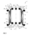
- FIG. 1 shows a spacer 1, which are used for example in a cryostat may be at ambient temperature (e.g., 300K) Cryostate wall with a cryogenic (e.g., 80K) radiation shield to connect, wherein the spacer 1 on the one hand a mechanical Connection and on the other hand a thermal insulation forms.
- ambient temperature e.g. 300K
- cryogenic e.g. 80K
- the spacer 1 consists essentially of a hollow cylindrical Upper part 2 and also a hollow cylindrical Lower part 3, wherein the lower part 3 has a larger Diameter than the upper part 2 and the upper part of the second sleeve-shaped surrounds.
- the upper part 2 has for attachment to the radiation shield of the cryostat on a base plate 4, in which several Holes 5 are located to the base plate 4 by rivets or Fix screws to the radiation shield of the cryostat.
- the lower part 3 also has a base plate 6, in the center is a hole 7, so that the base plate 6 of the lower part 3 screwed to the cryostat wall can be.
- the invention is in terms of the orientation of the spacer 1 not to the above described arrangement limited. It is also possible that the Upper part 2 is attached to the cryostat wall, whereas the lower part 3 is attached to the radiation shield.
- the upper part 2 and the lower part 3 in this case for example made of glass fiber reinforced plastic (GRP) or stainless steel, which have a relatively poor thermal conductivity, as opposed to the isolation of the cryogenic radiation shield the cryostat wall at ambient temperature is advantageous.
- GRP glass fiber reinforced plastic
- stainless steel which have a relatively poor thermal conductivity, as opposed to the isolation of the cryogenic radiation shield the cryostat wall at ambient temperature is advantageous.
- the mechanical connection between the upper part 2 and the Lower part 3 takes place here by several ropes 8-11, for example made of kevlar, in a circumferential annular gap are arranged between the upper part 2 and the lower part 3.
- the rope ends through End elements 20-29 are fixed in the holes 12-19.
- the end elements 20-29 can be, for example, nodes, Rope sleeves or clamps act.
- the ropes 8-11 are spatially differently aligned and take traction forces in different directions on, so that the spacer 1 on pressure, train and in the transverse direction can be charged.
- the ropes 8, 10 take this essentially compressive forces between the upper part 2 and the Lower part 3, while the other cables 9, 11 substantially Tensile forces between the upper part 2 and the lower part 3 take up.
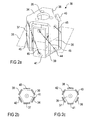
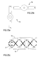
- Figure 2a shows an isometric view of an alternative Embodiment of a spacer 30, wherein Figure 2b a cross-sectional view of the spacer 30 with planar Strip along a cutting plane 31 in Figure 2a shows while Figure 2c is a cross-sectional view of the spacer 30 with circular arc-shaped strips, as for example by milling out of a pipe, through the cutting plane 31 shows.
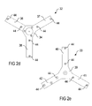
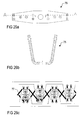
- the spacer 30 also consists essentially of a top 32 and a bottom 33, wherein Figure 2d the Upper part 32 in half-finished, i. not yet bent state shows, while Figure 2e the lower part 33 in half-finished State reproduces.
- the upper part 32 of the spacer 30 has a base plate 34 on, for example, by rivets or screws on the Radiation shield of a cryostat can be attached. For this are in the base plate 34 of the upper part 32 a plurality of holes 35 arranged.
- From the base plate 34 are for example at right angles several strips 36-38, with the strips 36-38 on the Scope of the upper part 32 distributed equidistantly arranged and each include gaps.
- the lower part 33 also has a base plate 39 which for example, attached to the cryostat wall of a cryostat can be.
- strips 36-38 and 40-42 are each at the base and at the free end holes 44 for receiving a or several ropes 45, which the upper part 32 with the lower part 33 tense.
- the individual cable sections between the holes 44 take here each traction forces in different Directions on, so that the entire spacer 30th can be loaded on train, pressure and in the transverse direction.
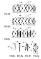
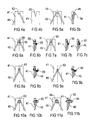
- FIGS 3a-3c show various embodiments the rope tension between the upper part 32 and the lower part 30 of the spacer 30.
- the cable tension shown in FIG. 3b also becomes only a single rope for the entire rope tension used, the rope 45 also alternately on the inside and guided on the outside of the spacer 30 becomes.
- the change between the inside and the outside However, the spacer 30 takes place in each case both in the passage through the holes 44 and between the strip 36-38 and the adjacent strips 40-42.
- FIGS. 3d and 3e indicate a fixation of the cable 45 a strip by means of a rivet 48, whereby a tilting the upper part 32 is prevented relative to the lower part 33.
- Figures 4a and 4b show alternative embodiments the strips 36-38 and 40-42, in which at the free end of the Strip 36-38 or 40-42 instead of the holes 44 a U-shaped cutout 52 or a V-shaped cutout 53, which has a clamping effect on the cable, is arranged through which the cable 45 can be performed.
- Another Difference between hooks 56 and 57 is that the hook 57 is pressed together, whereby the rope 45 in the hook 57 is clamped.
- Figures 8a and 8b and 9a and 9b show embodiments with a loose hook 59 or 60, in a hole 61 and 62 is mounted.
- the bore 61 is circular
- the bore 62 in the embodiment according to the figures 9a and 9b consists of a slot.
- the hook 60 must Therefore, when inserted into the bore 62 are rotated by 90 °.
- 60th Quick-acting glue used to make this before loading of the rope 45 provisionally to fix.
- the hooks 59, 60 can as well as the hook 57 pressed together in Figure 7c be used to clamp the rope 45.
- the cable 45 via a screw 63 and 64 out, the simply tightened for clamping can be.
- the screw 63 and 64 may be a Tin screw act or a standard screw, for the one Thread in the strip 41 must be cut. in principle is also the use of a mother on the back of the strip 41, the nut being spot-welded or sticking to the strip 41 can. If the thread of the screw 63 or 64 to their Head down, the rope can reach 45 by putting a narrow underfoot Ringes, a foil or the like to be protected.
- an intermediate ring 65 is used, which on the one hand enables that the thread does not reach to the screw head must and can not damage the rope 45 and on the other hand the breakpoint of the rope 45 on the strip 41 on moved to the outside. As a result, apart from the breakpoint, a thermal contact of the cable 45 with the strip 41 avoided.
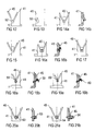
- Figures 12 to 21b show various embodiments for the guidance or fixation of the rope 41 at the base (Foot) of the strips 36-38 and 40-42, respectively, for simplicity only the strip 41 is shown. These embodiments correspond analogously to the embodiments in the figures 4a to 11b, so that to avoid References to the above description is and for corresponding components the same reference numerals be used.
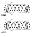
- Figures 22 and 23 show further embodiments of a rope tension.
- the embodiment according to FIG. 22 is distinguished here by a combination of a point welded hook 66 at the base of the strip 41 with a U-shaped recess 67th at the free end of the strip 41.
- both at the base and at the free end of the strip 41st point welded hooks 68, 69 are provided, each for fixing of the rope 45 are pressed together.
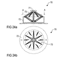
- Figures 24a and 24b show a further embodiment a spacer 70 according to the invention, which is an upper part 71 and a lower part 72, wherein the upper part 71, for example, on a radiation shield of a cryostat can be fixed while the lower part 72, for example can be attached to the cryostat wall.
- the upper part 71 in this case forms a hub, which in the center of the hollow cylindrical lower part 72 is arranged, wherein a or more ropes 73 spoke-shaped between the hub-shaped Upper part 71 and the lower part 72 are stretched.
- Figures 25a-25c and 26a-26c each show an embodiment a spacer according to the invention with a Upper part 74, 75 and a lower part 76, each two Have stripes.
- Figure 26a and 26b the upper part 75 and the lower part 75 are the same and the stripes are not perpendicular to the Baseplate.
- FIG. 26b shows a section through the finished component with respect to the cutting plane A-A of the half-finished Part in Fig. 26a.
- the spacer has in these embodiments so over four Strips arranged around the circumference.
- the mechanical connection takes place here, for example, as well by a tension by means of a rope 77, wherein in this example at each end of the strip a rope loop passed through two holes and with a screw rectangular insert disc is clamped.
Landscapes
- Engineering & Computer Science (AREA)
- Mechanical Engineering (AREA)
- General Engineering & Computer Science (AREA)
- Filling Or Discharging Of Gas Storage Vessels (AREA)
- Containers, Films, And Cooling For Superconductive Devices (AREA)
Applications Claiming Priority (2)
| Application Number | Priority Date | Filing Date | Title |
|---|---|---|---|
| DE102004006779 | 2004-02-11 | ||
| DE200410006779 DE102004006779B4 (de) | 2004-02-11 | 2004-02-11 | Abstandshalter |
Publications (1)
| Publication Number | Publication Date |
|---|---|
| EP1564477A1 true EP1564477A1 (fr) | 2005-08-17 |
Family
ID=34684009
Family Applications (1)
| Application Number | Title | Priority Date | Filing Date |
|---|---|---|---|
| EP05000705A Withdrawn EP1564477A1 (fr) | 2004-02-11 | 2005-01-14 | Entreoise |
Country Status (2)
| Country | Link |
|---|---|
| EP (1) | EP1564477A1 (fr) |
| DE (1) | DE102004006779B4 (fr) |
Cited By (2)
| Publication number | Priority date | Publication date | Assignee | Title |
|---|---|---|---|---|
| CN103438350A (zh) * | 2013-09-06 | 2013-12-11 | 宁波市天马空压机厂 | 具有冷干功能的储气罐 |
| GB2517746A (en) * | 2013-08-30 | 2015-03-04 | Ubh Internat Ltd | Storage tank suspension member and storage tank for storage of cryogenic liquid |
Citations (8)
| Publication number | Priority date | Publication date | Assignee | Title |
|---|---|---|---|---|
| DE495022C (de) * | 1930-04-01 | Industriegasverwertung M B H G | Transport- oder Druckgefaess fuer schwer verfluessigbare Gase | |
| US3155265A (en) * | 1964-11-03 | Thermal stress equalizing support system | ||
| DE1455594A1 (de) * | 1962-11-02 | 1968-12-12 | Chantiers De La Seine Maritime | Vorrichtung zur Aufhaengung von Tanks oder anderen Behaeltern |
| EP0135185A2 (fr) * | 1983-09-19 | 1985-03-27 | General Electric Company | Cryostat pour aimant par RMN |
| US4516405A (en) * | 1984-06-15 | 1985-05-14 | General Electric Company | Supporting tie configuration for cryostat for cold shipment of NMR magnet |
| US4721934A (en) * | 1987-04-02 | 1988-01-26 | General Electric Company | Axial strap suspension system for a magnetic resonance magnet |
| US6487866B1 (en) * | 2000-07-10 | 2002-12-03 | The United States Of America As Represented By The National Aeronautics & Space Administration | Multipurpose thermal insulation test apparatus |
| DE10128516A1 (de) * | 2001-06-13 | 2002-12-19 | Linde Ag | Speicherbehälter für kryogene Medien |
Family Cites Families (1)
| Publication number | Priority date | Publication date | Assignee | Title |
|---|---|---|---|---|
| DE19924768C1 (de) * | 1999-05-29 | 2001-02-15 | Karlsruhe Forschzent | Laser-Flash-Apparatur für kryogene Temperaturen |
-
2004
- 2004-02-11 DE DE200410006779 patent/DE102004006779B4/de not_active Expired - Fee Related
-
2005
- 2005-01-14 EP EP05000705A patent/EP1564477A1/fr not_active Withdrawn
Patent Citations (8)
| Publication number | Priority date | Publication date | Assignee | Title |
|---|---|---|---|---|
| DE495022C (de) * | 1930-04-01 | Industriegasverwertung M B H G | Transport- oder Druckgefaess fuer schwer verfluessigbare Gase | |
| US3155265A (en) * | 1964-11-03 | Thermal stress equalizing support system | ||
| DE1455594A1 (de) * | 1962-11-02 | 1968-12-12 | Chantiers De La Seine Maritime | Vorrichtung zur Aufhaengung von Tanks oder anderen Behaeltern |
| EP0135185A2 (fr) * | 1983-09-19 | 1985-03-27 | General Electric Company | Cryostat pour aimant par RMN |
| US4516405A (en) * | 1984-06-15 | 1985-05-14 | General Electric Company | Supporting tie configuration for cryostat for cold shipment of NMR magnet |
| US4721934A (en) * | 1987-04-02 | 1988-01-26 | General Electric Company | Axial strap suspension system for a magnetic resonance magnet |
| US6487866B1 (en) * | 2000-07-10 | 2002-12-03 | The United States Of America As Represented By The National Aeronautics & Space Administration | Multipurpose thermal insulation test apparatus |
| DE10128516A1 (de) * | 2001-06-13 | 2002-12-19 | Linde Ag | Speicherbehälter für kryogene Medien |
Cited By (4)
| Publication number | Priority date | Publication date | Assignee | Title |
|---|---|---|---|---|
| GB2517746A (en) * | 2013-08-30 | 2015-03-04 | Ubh Internat Ltd | Storage tank suspension member and storage tank for storage of cryogenic liquid |
| GB2517746B (en) * | 2013-08-30 | 2016-09-14 | Ubh Int Ltd | Storage tank suspension member and storage tank for storage of cryogenic liquid |
| CN103438350A (zh) * | 2013-09-06 | 2013-12-11 | 宁波市天马空压机厂 | 具有冷干功能的储气罐 |
| CN103438350B (zh) * | 2013-09-06 | 2015-05-20 | 宁波市天马空压机厂 | 具有冷干功能的储气罐 |
Also Published As
| Publication number | Publication date |
|---|---|
| DE102004006779B4 (de) | 2005-12-15 |
| DE102004006779A1 (de) | 2005-09-08 |
Similar Documents
| Publication | Publication Date | Title |
|---|---|---|
| DE102007009461A1 (de) | Führungsschiene einer Linearführung | |
| EP2263054B1 (fr) | Dispositif de fixation du carter d'un compresseur frigorifique | |
| WO2004088196A1 (fr) | Pied | |
| DE102017103772A1 (de) | Befestigungsvorrichtung und Befestigungsbaugruppe | |
| DE102010022415A1 (de) | Montagelasche für abgehängte Decken | |
| DE202012004615U1 (de) | Befestigungsystem | |
| DE3888239T2 (de) | Tieftemperaturhalterungssystem. | |
| DE102004006779B4 (de) | Abstandshalter | |
| CH687221A5 (de) | Automatische Klemmvorrichtung fuer Drahtseile oderRundprofile sowie Verwendung derselben. | |
| DE2526660C3 (de) | Gebäudekonstruktion mit einem Raumfachwerk aus Stäben und Knotenstücken und einer Außenhaut | |
| EP3611528B1 (fr) | Dispositif cryostat pourvu de système de bobines magnétiques supraconducteur à ancrage thermique de la structure de fixation | |
| DE102010028084B4 (de) | Elastisches Lager zur Aufhängung einer Abgasanlage mit einer einfach zu montierenden Grundplatte | |
| DE102013000624A1 (de) | Mutter zum Befestigen von Komponenten an einem profilierten Element über Schraubmittel und Verfahren zu deren Montage | |
| EP2288815B1 (fr) | Châssis assemblé par vis | |
| DE102017103768A1 (de) | Befestigungsvorrichtung und Befestigungsbaugruppe | |
| DE102016107519A1 (de) | Verbindungssystem aus Plattenelementen und Verbindungselementen | |
| EP1422362B1 (fr) | Dispositif de fixation de treillis de clôture à des poteaux de clôtures | |
| EP2916687A1 (fr) | Élément d'assemblage d'angle | |
| DE19852961C1 (de) | Unterteilungs- und Befestigungsvorrichtung für Ladegut, insbesondere in einem Laderaum von Kraftfahrzeugen | |
| AT511570A1 (de) | Balanciervorrichtung mit einer tragstruktur | |
| DE19740870C2 (de) | Stativ | |
| DE102017103771A1 (de) | Befestigungsvorrichtung und Befestigungsbaugruppe | |
| EP2092846B1 (fr) | Table | |
| DE202009008994U1 (de) | Gerüstkonstruktion | |
| AT504888B1 (de) | Behälter zur aufnahme von bei tiefen temperaturen, vorzugsweise unter 150 grad kelvin, aufzubewahrenden kryogenen medien und/oder geräten |
Legal Events
| Date | Code | Title | Description |
|---|---|---|---|
| PUAI | Public reference made under article 153(3) epc to a published international application that has entered the european phase |
Free format text: ORIGINAL CODE: 0009012 |
|
| AK | Designated contracting states |
Kind code of ref document: A1 Designated state(s): AT BE BG CH CY CZ DE DK EE ES FI FR GB GR HU IE IS IT LI LT LU MC NL PL PT RO SE SI SK TR |
|
| AX | Request for extension of the european patent |
Extension state: AL BA HR LV MK YU |
|
| 17P | Request for examination filed |
Effective date: 20060201 |
|
| AKX | Designation fees paid |
Designated state(s): FR |
|
| REG | Reference to a national code |
Ref country code: DE Ref legal event code: 8566 |
|
| RAP3 | Party data changed (applicant data changed or rights of an application transferred) |
Owner name: MAX-PLANCK-GESELLSCHAFT ZUR FOERDERUNG DER WISSENS |
|
| 17Q | First examination report despatched |
Effective date: 20090514 |
|
| STAA | Information on the status of an ep patent application or granted ep patent |
Free format text: STATUS: THE APPLICATION IS DEEMED TO BE WITHDRAWN |
|
| 18D | Application deemed to be withdrawn |
Effective date: 20090804 |