EP1564458B1 - Ventil - Google Patents
Ventil Download PDFInfo
- Publication number
- EP1564458B1 EP1564458B1 EP05001872A EP05001872A EP1564458B1 EP 1564458 B1 EP1564458 B1 EP 1564458B1 EP 05001872 A EP05001872 A EP 05001872A EP 05001872 A EP05001872 A EP 05001872A EP 1564458 B1 EP1564458 B1 EP 1564458B1
- Authority
- EP
- European Patent Office
- Prior art keywords
- housing
- section
- sealing
- valve
- sealing element
- Prior art date
- Legal status (The legal status is an assumption and is not a legal conclusion. Google has not performed a legal analysis and makes no representation as to the accuracy of the status listed.)
- Expired - Lifetime
Links
- 238000007789 sealing Methods 0.000 claims abstract description 159
- 230000000694 effects Effects 0.000 claims abstract description 11
- 230000007704 transition Effects 0.000 claims description 26
- 239000000463 material Substances 0.000 claims description 14
- 125000006850 spacer group Chemical group 0.000 claims description 14
- 239000011324 bead Substances 0.000 claims description 12
- 229920001971 elastomer Polymers 0.000 claims description 5
- 239000000806 elastomer Substances 0.000 claims description 4
- 238000004873 anchoring Methods 0.000 claims description 3
- 229920002725 thermoplastic elastomer Polymers 0.000 claims description 3
- 230000002093 peripheral effect Effects 0.000 claims 1
- 239000002861 polymer material Substances 0.000 claims 1
- 238000003825 pressing Methods 0.000 claims 1
- 239000012530 fluid Substances 0.000 description 7
- 239000013536 elastomeric material Substances 0.000 description 4
- 238000004519 manufacturing process Methods 0.000 description 4
- 238000011161 development Methods 0.000 description 2
- 230000018109 developmental process Effects 0.000 description 2
- 238000009826 distribution Methods 0.000 description 2
- 238000002347 injection Methods 0.000 description 2
- 239000007924 injection Substances 0.000 description 2
- 238000001746 injection moulding Methods 0.000 description 2
- 229910052751 metal Inorganic materials 0.000 description 2
- 239000002184 metal Substances 0.000 description 2
- 238000000034 method Methods 0.000 description 2
- 230000003068 static effect Effects 0.000 description 2
- 230000003213 activating effect Effects 0.000 description 1
- 230000006835 compression Effects 0.000 description 1
- 238000007906 compression Methods 0.000 description 1
- 230000006735 deficit Effects 0.000 description 1
- 238000013461 design Methods 0.000 description 1
- 238000006073 displacement reaction Methods 0.000 description 1
- 238000003780 insertion Methods 0.000 description 1
- 230000037431 insertion Effects 0.000 description 1
- 238000009434 installation Methods 0.000 description 1
- 230000007257 malfunction Effects 0.000 description 1
- 229910001092 metal group alloy Inorganic materials 0.000 description 1
- 150000002739 metals Chemical class 0.000 description 1
- 239000004033 plastic Substances 0.000 description 1
- 238000002360 preparation method Methods 0.000 description 1
- 239000003566 sealing material Substances 0.000 description 1
- 238000013022 venting Methods 0.000 description 1
Images


Classifications
-
- F—MECHANICAL ENGINEERING; LIGHTING; HEATING; WEAPONS; BLASTING
- F16—ENGINEERING ELEMENTS AND UNITS; GENERAL MEASURES FOR PRODUCING AND MAINTAINING EFFECTIVE FUNCTIONING OF MACHINES OR INSTALLATIONS; THERMAL INSULATION IN GENERAL
- F16K—VALVES; TAPS; COCKS; ACTUATING-FLOATS; DEVICES FOR VENTING OR AERATING
- F16K11/00—Multiple-way valves, e.g. mixing valves; Pipe fittings incorporating such valves
- F16K11/02—Multiple-way valves, e.g. mixing valves; Pipe fittings incorporating such valves with all movable sealing faces moving as one unit
- F16K11/06—Multiple-way valves, e.g. mixing valves; Pipe fittings incorporating such valves with all movable sealing faces moving as one unit comprising only sliding valves, i.e. sliding closure elements
- F16K11/065—Multiple-way valves, e.g. mixing valves; Pipe fittings incorporating such valves with all movable sealing faces moving as one unit comprising only sliding valves, i.e. sliding closure elements with linearly sliding closure members
- F16K11/07—Multiple-way valves, e.g. mixing valves; Pipe fittings incorporating such valves with all movable sealing faces moving as one unit comprising only sliding valves, i.e. sliding closure elements with linearly sliding closure members with cylindrical slides
- F16K11/0712—Multiple-way valves, e.g. mixing valves; Pipe fittings incorporating such valves with all movable sealing faces moving as one unit comprising only sliding valves, i.e. sliding closure elements with linearly sliding closure members with cylindrical slides comprising particular spool-valve sealing means
-
- F—MECHANICAL ENGINEERING; LIGHTING; HEATING; WEAPONS; BLASTING
- F16—ENGINEERING ELEMENTS AND UNITS; GENERAL MEASURES FOR PRODUCING AND MAINTAINING EFFECTIVE FUNCTIONING OF MACHINES OR INSTALLATIONS; THERMAL INSULATION IN GENERAL
- F16K—VALVES; TAPS; COCKS; ACTUATING-FLOATS; DEVICES FOR VENTING OR AERATING
- F16K31/00—Actuating devices; Operating means; Releasing devices
- F16K31/12—Actuating devices; Operating means; Releasing devices actuated by fluid
- F16K31/122—Actuating devices; Operating means; Releasing devices actuated by fluid the fluid acting on a piston
- F16K31/1221—Actuating devices; Operating means; Releasing devices actuated by fluid the fluid acting on a piston one side of the piston being spring-loaded
Definitions
- the invention relates to a valve with a valve housing which has a provided for receiving a valve spool, circumferentially bounded by a housing wall elongated housing recess into which opens laterally at least one valve channel and in which a valve spool penetrated sealing means is arranged, which has a sealing housing supporting at least one annular sealing element having an outer portion with an outer sealing area for sealing against the housing recess and an inner portion with an inner sealing area for sealing against the valve slide.
- Such a valve is for example from the DE 41 01 049 C2 in which a sealing device for a multi-way valve is described, in which a retaining sleeve is provided which can be inserted into a receptacle and a plurality of annular sealing elements, each having both an inner sealing edge for sealing against the valve spool and an outer sealing edge for sealing against having the housing recess.
- a sealing arrangement for a piston valve which has circular, in cross-section Y- or I-shaped sealing elements between two spacer elements be clamped and form a seal on the one hand with respect to the housing wall of the valve housing and on the other hand with respect to the piston guided in the housing recess of the piston valve.
- a multi-way valve known, with a housing having a housing recess in which a valve slide is mounted axially displaceable.
- the housing bore which is referred to as a guide bore, is graduated, wherein, viewed from the mounting opening, smaller-diameter sections are provided.
- the respective sections of the guide bore are each equipped with a spacer-sealing ring combination consisting of a spacer and an annular sealing element.
- the sealing elements serve both to seal against the wall of the respective guide bore portion and to seal against the valve spool.
- a slide valve seal is known in which separate seals are used to seal against the valve spool and to seal against the housing recess of the valve housing.
- an O-ring is used, while the seal against the valve slide via an angled sealing ring, the axially extending end portion can be positively locked axially to a spacer ring.
- a problem of the previously described prior art is the mounting of the sealing device or the seals in the housing recess of the valve housing.
- the housing recess laterally open a plurality of valve channels, which interrupt the otherwise closed and smooth wall of the housing recess, wherein the mouth edges of the valve channel mouths may be formed relatively sharp.
- the seal In order to achieve a sealing effect with respect to the housing recess, the seal must be pressed into contact with the housing wall.
- Conventional valves already have the final, sealing radial position of the seals during assembly, so there is a risk that the seals will be damaged when pushed over sharp-edged edges of the valve port orifices. To remedy this problem, it is already known to use mounting aids that help the seals over the area of the opening valve channels.
- the object of the invention is to provide a valve of the type mentioned, in which the sealing device is easy, quick and reliable mountable.
- the valve according to the invention is characterized in that the sealing housing in the region of the sealing element has two sealing element between them, annular housing elements, wherein at least one of the housing elements on the outer portion axially associated side has at least one urging means, which during clamping of the Housing elements locally acts on the outer portion such that the outer portion to achieve a sealing effect is pressed radially outwardly against the housing wall and wherein at least one decoupling means is provided which causes the inner portion of the resulting from the application of the outer portion, radially inwardly directed forces is decoupled.
- the sealing effect preferably unfolds only when the relevant sealing element has reached its previously determined axial position along the housing recess and the two, the respective sealing element flanking housing elements are clamped together, wherein the outer portion of the sealing element is pressed radially outwardly against the housing wall.
- the decoupling means or decoupling means in addition to the "decoupling of force", means that a manufacturing tolerance at the outer sealing area of the outer portion has no influence on the inner sealing area. It can thus be prevented that for the seal against the housing recess, which can also be referred to as a static seal with static sealing edge, required radial forces and / or tolerances are not transmitted to the inner portion of the sealing element, so that the seal against the valve spool - also referred to as dynamic sealing with dynamic sealing edge - this is essentially unaffected.
- the problem is avoided that the inner sealing area presses on the valve slide when the outer section is acted upon, which would lead to increased friction between the valve slide and the sealing element, whereby the increased friction could lead to a malfunction when switching the valve.
- the outer portion of the seal member has an outer-section radial plane including the outer seal portion, and the inner portion has an inner-portion radial plane containing the inner seal portion.
- a decoupling means provided between the outer portion and inner portion, on the one hand connected to the outer portion and the other with the inner portion, transversely aligned to the outer and inner portion transition portion provided which causes the outer portion radial plane axially offset from the inner portion radial plane
- the sealing element may thus have an angled or stepped shape.
- the transition section is aligned substantially perpendicular or at approximately 90 ° to the outer and the inner portion. The outer and inner sections can thus be aligned in the assembled state of the sealing device in the radial direction, while the transition section extends substantially in the axial direction.
- the housing elements may be adapted to the shape of the sealing element, for example, they may have housing transition portions which are formed in the mounted state of the sealing device corresponding to the transition portion of the sealing element.
- the housing elements can thus also be angled or stepped.
- outer section, transition section and inner section are integrally connected to one another. They can therefore be produced by a single manufacturing process.
- outer section, transition section and inner section are made of the same material, in particular elastomeric material. It is possible to produce such a sealing element by an elastomer injection method.
- thermoplastic elastomer is used. However, other Elastormerart can be used.
- the sealing device has at least one first housing element, which is in particular positively connected to the sealing element by means of holding means and has at least a second housing element which has at least one urging means for acting on the outer portion of the sealing element.
- the urging means is integrally connected to the second housing member.
- the urging means is formed as a separate component and to fasten it to the relevant housing element.
- an annular bead is provided as a loading means, which projects axially from the side of the second housing element assigned to the outer portion of the sealing element. When the housing elements are clamped together, the bead can "dig in” in the outer section, so that it is pressed radially outwards onto the housing wall.
- the bead is preferably made of a harder material compared to the outer portion, so that the application of the outer portion results in a deformation of the outer portion and not a deformation of the bead.
- the holding means via which the first housing element and the sealing element can be connected to one another in particular in a form-fitting manner, are preferably integrally formed on the sealing element. So you can form part of the sealing element. Alternatively, it would be possible to provide the holding means on the housing element.
- the sealing element is held only by a form-fitting retaining means on the respective housing element, so that the outer portion can deform in radial directions, in contrast to a full-surface cohesive connection between the sealing element and the housing element, wherein the sealing element fixed and in radial directions immovably connected to the housing element.
- the first housing element may have on its rear side facing away from the annular sealing element an annular groove for receiving a corresponding thereto formed anchoring part of the associated holding means, wherein the groove extending over axially extending, in particular at regular intervals over the circumference of the groove, accessed by the holding means Openings, in particular cylindrical bores, is connected to the front side of the first housing element.
- the seal housing may consist of a plurality of first and a plurality of second housing elements, wherein the first and / or second housing elements on its rear side facing away from the sealing element via spacers or spacer elements with adjacent first or second housing elements are coupled. It is possible that the first housing element is coupled via proximity switches with an adjacent second and the second housing element accordingly with an adjacent first housing element.
- the spacers are located only on the back sides of the second, the loading means having housing elements, in particular, the spacers are integrally connected to the second housing element.
- the first and second housing members may be made of the same material, such as polymeric material. However, other materials can also be used, for example metals and / or metal alloys.
- FIG. 1 shows a valve 11 as part of a designated generally by reference numeral 12 valve assembly, which additionally has a preferably plate-like fluid distributor 13, on which the valve 11 is releasably secured by means of suitable fastening means 14.
- the valve 11 serves to control fluid flows and is designed as a multi-way valve.
- the medium to be controlled is in particular compressed air, although it may also be another gaseous or hydraulic medium.
- the valve 11 has a valve housing 15, in which at least one linearly extending, elongated housing recess 16 is provided. On the circumference, the housing recess 16 is bounded by a housing wall 17 of the valve housing 15.
- the housing wall 17 and in particular the entire valve housing 15 consist in the embodiment of plastic material.
- the preparation is advantageously carried out by injection molding, wherein a reworking of the housing recess 16 defining and radially inwardly oriented wall surface 18 of the housing wall 17 is not required or only to a small extent.
- a design made of metal would also be possible in principle.
- valve channels 19 a In the housing recess 16 open in the region of the wall surface 18 at a plurality of spaced in the longitudinal direction of the housing recess 16 locations valve channels 19 a. These pass through the housing wall 17 and form at its outer end connection openings 20. According to a preferred embodiment, three of these connection openings open to an outer mounting surface 21 of the valve housing 15, with which the valve 11 is attached to a mounting surface 22 of the fluid manifold 13. In the latter run a plurality of fluid distribution channels 23, which open to the mounting surface 22 and communicate there with the connection openings 20 in pairs.
- connection openings 20 open on a mounting surface 21 in particular opposite terminal surface 24 of the valve housing 15 and are intended to allow the connection not shown fluid lines leading to a consumer to be driven.
- the valve 11 of the embodiment is a 4/2-way valve. However, it is also conceivable to use 3/2 or 5/2-way valves.
- the valve channels 19 opening out to the mounting surface 21 are a central feed channel 19a, which is flanked axially by a venting channel 19b.
- the two leading to the terminal surface 24 valve channels 19 are working channels 19c and 19d.
- valves 11 On the fluid distributor 13, a plurality of valves 11 may be positioned, which are each associated with the correct allocation with the fluid distribution channels 23.
- valve spool 25 In the housing recess 16, an elongated piston-like valve spool 25 is arranged. He has several control sections 26 larger diameter, between each of which a control portion 27 of smaller diameter is placed.
- the valve spool 25 associated actuating means allow an axial displacement and positioning of the valve spool 25 in the housing recess 16 relative to the valve housing 15th
- the actuating means comprise a drive piston 28, which is in operative connection with the valve slide 25 at one end.
- the latter is displaceably guided under sealing in a end section of the housing recess 16 designated as actuating space 29.
- valve spool 25 opposite side of the drive piston 28 lying outer portion 30 of the actuating chamber 29 communicates in a manner not shown with a control channel 31 via which a fluidic control medium can be selectively supplied or removed.
- the corresponding control takes over an electrically activatable pilot valve 32 which is attached to the valve housing 15.
- Comparable actuation means may also be associated with the opposite end of the valve spool 25. Notwithstanding this, there is in the embodiment, however, only one return spring 33, which is effective between the valve housing 15 and the valve spool 25 and the valve spool 25 constantly applied in the direction of the drive piston.
- the valve slide 25 In the deactivated state of the pilot valve 32, the valve slide 25, due to the bias of the return spring 33, assumes the first switching position shown in the drawing.
- the pilot valve 32 By activating the pilot valve 32 is the drive piston 28 and thus the valve spool 25 is displaced with simultaneous compression of the return spring 33 to the right in a second switching position.
- the housing recess 16 is closed at both end sides. On at least one end side, the closure is effected by a closure cover 34 detachably fastened to the valve housing 15. In the removed state of the closure lid 34, the housing recess 16 is accessible from the corresponding front side.
- housing recess 16 In the housing recess 16 is an effective between the valve spool 25 and the housing wall 17 sealing means 35. It sits coaxially between the wall surface 18 and the valve spool 25, being interspersed coaxially by the latter.
- the sealing device has a sealing housing 36, which in turn is composed of at least one, preferably of a plurality of sealing units 37, wherein according to the embodiment, four or five sealing units 37 are provided.
- a sealing unit 37 is constructed in each case from a first, annular housing element 38a and a second, annular housing element 38b adjacent in the axial direction, an annular sealing element 39 being fixed between the first and second housing element 38a, 38b.
- the sealing element 39 consists of an outer section 40 with an outer sealing region 41 for sealing against the housing recess 16 and an inner section 42 with an inner sealing region 43 for sealing against the valve slide 25.
- the urging means is exemplified in the form of an annular, located on the housing outer portion 44b of the second housing member 38b, to be acted upon sealing member 39 facing bead 46.
- the bead 46 can penetrate into the outer section 40, so that the outer section deforms radially outward, thus achieving a sealing effect with respect to the housing recess 16.
- loading means on both housing elements 38a, 38b, for example to provide two opposing beads 46, between which the outer portion 40 of the sealing element 39 is clamped.
- An alternative is to provide a biasing means on the first housing member.
- the sealing element 39 further has at least one decoupling means 47, which causes the inner portion 42 of the sealing element 39 of the resulting from the application of the outer portion 40, radially inwardly directed Forces is decoupled.
- the decoupling means is exemplified by means of a transition section 47 which is arranged transversely to the outer and the inner portion 40, 41 of the sealing element 39 and is connected at one end to the outer portion 40 and the other end to the inner portion 41. It is achieved by the transition section 47 that the outer section radial plane 48 of the outer section 40, which contains the outer sealing area, is arranged axially offset from the inner section radial plane 49 of the inner section which contains the inner sealing area.
- the sealing element 39 has the overall shape of a stepped or stepped sealing ring, wherein outer portion, transition portion and inner portion 40, 42, 47 are integrally connected to each other and can be produced by a single sealing element manufacturing process.
- the sealing element 39 is made of a relatively soft elastomeric material, which is preferably softer than the bead 46 on the second housing element 38b, so that this can penetrate when clamping the housing elements 38a, 38b in the soft elastomeric material and deform the outer portion 40, so that the outer Sealing region 41 is pressed against the wall surface 18 of the housing wall 17.
- elastomeric material for example, a thermoplastic elastomer can be used.
- the first housing element 38a which can also be referred to as a carrier part, is intended to carry the sealing element 39.
- the holding means 50 are formed by the sealing element 39 itself, in particular, they are formed in the manufacture of the sealing element 39 with.
- the first housing element 38a is formed such that the sealing element 39 integrally formed thereon, preferably by means of an injection process, for example by means of an elastomer injection molding process can be molded on it.
- the first housing element 38a has, on its rear side opposite the sealing element 39, an annular, circumferential groove 52, on the groove base of which openings 53 are provided which open out at the front side of the first housing element 38a.
- the annular groove 52 and the openings 53 which are preferably formed as holes with a circular cross-section, serve to receive anchoring parts 54 of the holding means 50. It is possible, for example, the sealing element 39 from the back of the first housing member 38a forth first the annular groove 52 filling be sprayed so that plasticized sealing element material passes through the openings 53 to the inside and there is taken in a predetermining the shape of the sealing element 39 negative mold and solidifies there to its final shape.
- the individual sealing units 37 of the sealing device 35 are arranged at regular intervals along the housing recess 16 of the valve housing 15. This regular spacing is achieved by spacers or spacer elements 55, which are preferably fastened to the outside of the second housing element 38b facing away from the sealing element 39.
- the assembly of the sealing device 35 according to the embodiment shown from the side on which the pilot valve 32 is located, ie in a mounting direction 51 from left to right.
- first a first housing element 38a, together with the sealing element 39 fastened thereto, is inserted into the housing recess 16 until it reaches its predetermined location along the housing recess 16, which is formed by a graduation 56 on the closure cover 34 in the exemplary embodiment shown.
- the laterally opening into the housing recess 16 valve channels 19a to 19d are passed.
- the sealing elements relax when they are pressed over the mouths of the valve channels. As a result, the rubber elastic sealing material slightly deforms into the mouths. If the sealing device 35 is then pressed further in the mounting direction 51, the section of the sealing element deformed into the mouth remains hanging from the edge of the mouth, which can lead to damage of the sealing element.
- the sealing element 39 is not under tension during mounting, that is, it is not yet pressed against the wall surface 18 of the housing recess 6. The sealing effect is generated only with the clamping together of the two housing elements 38a, 38b.
- the sealing element 39 to be mounted also does not deform into the channel openings of the valve channels to be passed, which prevents the effect described above.
- the associated, second housing element 38b is inserted and clamped together with the first housing element, wherein the bead 46 located on the housing outer portion 44b of the second housing element 38b is pressed into the outer portion 40 of the sealing element 39, so that the outer portion 40 and thus the outer sealing region 41 radially outwardly deformed and a sealing effect against the wall surface 18 of the housing wall 17 is achieved.
- the transition section 47 formed between the outer section 40 and the inner section 42 and located transversely to these two sections prevents the inner section 42 from being deformed.
- the second housing element 38b On the outside of the second housing element 38b facing away from the sealing element 39, there are several, in particular three spacers 55 distributed over the circumference of the second housing element 38b, which determine the position of the next sealing unit 37 lying in front in the mounting direction 51.
- a first housing element together with sealing element 39 is inserted until it abuts the spacer.
- five sealing units 37 can be inserted gradually.
- the second housing element 38b no longer has a spacer 55, but expediently toothing means 57 with which this sealing unit 37 is fixed in the housing recess 16 and the entire sealing device 35 is latched against being pulled out against the mounting direction 51.
Landscapes
- Engineering & Computer Science (AREA)
- General Engineering & Computer Science (AREA)
- Mechanical Engineering (AREA)
- Multiple-Way Valves (AREA)
- Valve Housings (AREA)
- Magnetically Actuated Valves (AREA)
- Electrically Driven Valve-Operating Means (AREA)
- Temperature-Responsive Valves (AREA)
- Check Valves (AREA)
Description
- Die Erfindung betrifft ein Ventil mit einem Ventilgehäuse, das eine zur Aufnahme eines Ventilschiebers vorgesehene, umfangsseitig von einer Gehäusewand begrenzte längliche Gehäuseausnehmung aufweist, in die seitlich mindestens ein Ventilkanal einmündet und in der eine vom Ventilschieber durchsetzte Dichtungseinrichtung angeordnet ist, die ein Dichtungs-Gehäuse besitzt, das wenigstens ein ringförmiges Dichtelement hält, das einen Außenabschnitt mit äußerem Dichtbereich zur Abdichtung gegenüber der Gehäuseausnehmung und einen Innenabschnitt mit innerem Dichtbereich zur Abdichtung gegenüber dem Ventilschieber besitzt.
- Ein derartiges Ventil ist beispielsweise aus der
DE 41 01 049 C2 bekannt, in der eine Dichtungseinrichtung für ein Mehrwegeventil beschrieben ist, bei der eine Halterungshülse vorgesehen ist, die in eine Aufnahme eingeschoben werden kann und mehrere ringförmige Dichtelemente aufweist, die jeweils sowohl eine innere Dichtkante zur Abdichtung gegenüber dem Ventilschieber und eine äußere Dichtkante zur Abdichtung gegenüber der Gehäuseausnehmung aufweisen. - In der
US 2,892,644 ist eine Dichtungsanordnung für ein Kolbenventil offenbart, die kreisförmige, im Querschnitt Y- bzw. I-förmige Dichtelemente besitzt, die zwischen zwei Distanzelementen eingespannt werden und eine Abdichtung einerseits gegenüber der Gehäusewand des Ventilgehäuses sowie andererseits gegenüber dem in der Gehäuseausnehmung des Kolbenventils geführten Kolben bilden. - Aus der
DE 30 43 871 ist ein Mehrwegeventil bekannt, mit einem Gehäuse, das eine Gehäuseausnehmung besitzt, in der ein Ventilschieber axial verschieblich gelagert ist. Die als Führungsbohrung bezeichnete Gehäuseausnehmung ist abgestuft, wobei, von der Montageöffnung aus gesehen im Durchmesser kleiner werdende Abschnitte vorgesehen sind. Die jeweiligen Abschnitte der Führungsbohrung sind mit jeweils einer Distanzstück-Dichtring-Kombination, bestehend aus einem Distanzstück und einem ringförmigen Dichtelement bestückbar. Die Dichtelemente dienen sowohl zur Abdichtung gegenüber der Wandung des jeweiligen Führungsbohrungsabschnitts als auch zur Abdichtung gegenüber dem Ventilschieber. - Aus der
DE 32 40 552 A1 ist eine Schieberventildichtung bekannt, bei der zur Abdichtung gegenüber dem Ventilschieber und zur Abdichtung gegenüber der Gehäuseausnehmung des Ventilgehäuses jeweils separate Dichtungen verwendet werden. Zur Abdichtung gegenüber der Gehäuseausnehmung wird ein O-Ring verwendet, während die Abdichtung gegenüber dem Ventilschieber über einen abgewinkelten Dichtungsring erfolgt, dessen axial verlaufendes Endteil formschlüssig an einem Distanzring axial verrastet werden kann. - Ein Problem des zuvor geschilderten Standes der Technik ist die Montage der Dichtungseinrichtung bzw. der Dichtungen in der Gehäuseausnehmung des Ventilgehäuses. In die Gehäuseausnehmung münden seitlich mehrere Ventilkanäle ein, die die ansonsten geschlossene und glatte Wandung der Gehäuseausnehmung unterbrechen, wobei die Mündungsränder der Ventilkanalmündungen relativ scharfkantig ausgebildet sein können. Um eine Dichtwirkung gegenüber der Gehäuseausnehmung zu erzielen, muss die Dichtung im Presssitz an der Gehäusewandung anliegen. Bei herkömmlichen Ventilen ist bereits bei der Montage die endgültige, dichtende Radialposition der Dichtungen vorhanden, so dass die Gefahr besteht, dass die Dichtungen beschädigt werden, wenn sie über scharfkantige Ränder der Ventilkanalmündungen geschoben werden. Um diesem Problem abzuhelfen ist es bereits bekannt, Montagehilfen zu verwenden, die den Dichtungen über den Bereich der einmündenden Ventilkanäle hinweghelfen.
- Aufgabe der Erfindung ist es ein Ventil der eingangs erwähnten Art zu schaffen, bei dem die Dichteinrichtung einfach, schnell und zuverlässig montierbar ist.
- Diese Aufgabe wird durch ein Ventil mit den Merkmalen des unabhängigen Anspruchs 1 gelöst. Weiterbildungen der Erfindung sind in den Unteransprüchen dargestellt.
- Das erfindungsgemäße Ventil zeichnet sich dadurch aus, dass das Dichtungs-Gehäuse im Bereich des Dichtelementes zwei das Dichtelement zwischen sich fixierende, ringförmige Gehäuseelemente aufweist, wobei wenigstens eines der Gehäuseelemente an der dem Außenabschnitt axial zugeordneten Seite über wenigstens ein Beaufschlagungsmittel verfügt, das beim Zusammenspannen der Gehäuseelemente lokal den Außenabschnitt derart beaufschlägt, dass der Außenabschnitt zur Erzielung einer Dichtwirkung radial nach außen gegen die Gehäusewand pressbar ist und wobei wenigstens ein Entkopplungsmittel vorgesehen ist, das bewirkt, dass der Innenabschnitt von den aus der Beaufschlagung des Außenabschnittes resultierenden, nach radial innen gerichteten Kräften entkoppelt ist.
- Bei Montage der Dichtungseinrichtung ist noch keine Pressung zwischen der Gehäusewand und den Dichtelementen vorhanden, so dass diese "gefahrlos" über scharfkantige Mündungsränder einmündender Ventilkanäle hinweg gelangen können. Zusätzliche Montagehilfen sind hierfür nicht notwendig. Die Dichtwirkung entfaltet sich vorzugsweise erst dann, wenn das betreffende Dichtelement seine zuvor bestimmte Axialposition entlang der Gehäuseausnehmung erreicht hat und die beiden, das betreffende Dichtelement flankierenden Gehäuseelemente zusammengespannt werden, wobei der Außenabschnitt des Dichtelements radial nach außen gegen die Gehäusewand gepresst wird.
- Das oder die Entkopplungsmittel bewirken zusätzlich zur "Kraft-Entkopplung", dass eine Fertigungstoleranz am äußeren Dichtbereich des Außenabschnitts keinen Einfluss auf den inneren Dichtbereich hat. Es kann also verhindert werden, dass für die Abdichtung gegenüber der Gehäuseausnehmung, die auch als statische Abdichtung mit statischer Dichtkante bezeichnet werden kann, erforderlichen Radialkräfte und/oder Toleranzen nicht auf den Innenabschnitt des Dichtelements übertragen werden, so dass die Abdichtung gegenüber dem Ventilschieber - auch als dynamische Abdichtung mit dynamischer Dichtkante bezeichnet - davon im Wesentlichen unbeeinflusst ist. Es wird also insbesondere das Problem vermieden, dass der innere Dichtbereich bei Beaufschlagung des Außenabschnitts auf den Ventilschieber drückt, was zu einer erhöhten Reibung zwischen Ventilschieber und Dichtelement führen würde, wobei die erhöhte Reibung zu einer Fehlfunktion beim Schalten des Ventils führen könnte.
- Der Außenabschnitt des Dichtelements besitzt eine den äußeren Dichtbereich enthaltende Außenabschnitts-Radialebene und der Innenabschnitt eine den inneren Dichtbereich enthaltende Innenabschnitts-Radialebene. Vorzugsweise ist als Entkopplungsmittel ein zwischen dem Außenabschnitt und Innenabschnitt befindlicher, einerseits mit dem Außenabschnitt und andererseits mit dem Innenabschnitt verbundener, quer zum Außen- und zum Innenabschnitt ausgerichteter Übergangsabschnitt vorgesehen, der bewirkt, dass die Außenabschnitts-Radialebene axial versetzt zur Innenabschnitts-Radialebene angeordnet ist. Das Dichtelement kann also eine abgewinkelte bzw. abgestufte Gestalt aufweisen. Vorzugsweise ist der Übergangsabschnitt im wesentlich senkrecht bzw. im ca. 90° Winkel zum Außen- und zum Innenabschnitt ausgerichtet. Außen- und Innenabschnitt können also im montierten Zustand der Dichtungseinrichtung in radialer Richtung ausgerichtet sein, während der Übergangsabschnitt im wesentlichen in axialer Richtung verläuft.
- Die Gehäuseelemente können an die Form des Dichtelements angepasst sein, beispielsweise können sie Gehäuse-Übergangsabschnitte besitzen, die im montierten Zustand der Dichtungseinrichtung korrespondierend zum Übergangsabschnitt des Dichtelements ausgebildet sind. Die Gehäuseelemente können also ebenfalls abgewinkelt bzw. abgestuft ausgebildet sein.
- Radial zwischen dem Übergangsabschnitt des Dichtelements und dem den Übergangsabschnitt radial innen flankierenden Gehäuse-Übergangsabschnitt insbesondere des die Beaufschlagung des Außenabschnitts bewirkenden Gehäuseelements ist im montierten Zustand der Dichtungseinrichtung ein Freiraum bzw. Spalt ausgebildet. Dies hat den Vorteil, dass sich der Außenabschnitt bei Beaufschlagung durch das oder die Beaufschlagungsmittel am Gehäuseelement radial in beide Richtungen, also sowohl nach radial innen als nach radial außen verformen kann, wobei sich die Verformung nach innen infolge des Entkopplungsmittels nicht auf den Außenabschnitt überträgt.
- Besonders bevorzugt sind Außenabschnitt, Übergangsabschnitt und Innenabschnitt einstückig miteinander verbunden. Sie können also durch einen einzigen Herstellungsprozess hergestellt werden. In bevorzugter Weise sind Außenabschnitt, Übergangsabschnitt und Innenabschnitt aus demselben Material hergestellt, insbesondere aus Elastomermaterial. Es ist möglich ein solches Dichtelement durch ein Elastomer-Spritzverfahren herzustellen. Vorzugsweise wird thermoplastisches Elastomer verwendet. Es sind jedoch auch andere Elastormerarten einsetzbar.
- Bei einer Weiterbildung der Erfindung besitzt die Dichteinrichtung wenigstens ein erstes Gehäuseelement, das mittels Haltemitteln insbesondere formschlüssig mit dem Dichtelement verbunden ist und weist wenigstens ein zweites Gehäuseelement auf, das über das wenigstens eine Beaufschlagungsmittel zur Beaufschlagung des Außenabschnitts des Dichtelements verfügt.
- Vorzugsweise ist das Beaufschlagungsmittel einstückig mit dem zweiten Gehäuseelement verbunden. Prinzipiell wäre es jedoch auch möglich das Beaufschlagungsmittel als separates Bauteil auszubilden und am betreffenden Gehäuseelement zu befestigen. In bevorzugter Weise ist als Beaufschlagungsmittel ein ringförmiger Wulst vorgesehen, der von der dem Außenabschnitt des Dichtelements zugeordneten Seite des zweiten Gehäuseelements axial hervorsteht. Beim Zusammenspannen der Gehäuseelemente kann sich der Wulst in den Außenabschnitt "eingraben", so dass dieser radial nach außen auf die Gehäusewand gepresst wird. Der Wulst ist vorzugsweise aus einem im Vergleich zum Außenabschnitt härteren Material hergestellt, so dass die Beaufschlagung des Außenabschnitts eine Verformung des Außenabschnitts und nicht eine Verformung des Wulstes ergibt.
- Die Haltemittel, über die das erste Gehäuseelement und das Dichtelement insbesondere formschlüssig miteinander verbunden werden können, sind vorzugsweise an das Dichtelement angeformt. Sie können also einen Teil des Dichtelements bilden. Alternativ wäre es möglich die Haltemittel am Gehäuseelement vorzusehen. In bevorzugter Weise wird das Dichtelement lediglich durch ein einen Formschluss bildende Haltemittel am betreffenden Gehäuseelement gehalten, so dass sich der Außenabschnitt in radiale Richtungen verformen kann, im Gegensatz zu einer vollflächig stoffschlüssigen Verbindung zwischen Dichtelement und Gehäuseelement, bei der das Dichtelement fest und in radiale Richtungen unbeweglich mit dem Gehäuseelement verbunden ist.
- Das erste Gehäuseelement kann an seiner dem ringförmigen Dichtelement abgewandten Rückseite eine ringförmige Nut zur Aufnahme einer korrespondierend dazu ausgebildeten Verankerungspartie des zugeordneten Haltemittels aufweisen, wobei die Nut über in axialer Richtung verlaufende, insbesondere in regelmäßigen Abständen über den Umfang der Nut verteilte, von den Haltemitteln durchgriffene Öffnungen, insbesondere zylindrische Bohrungen, mit der Vorderseite des ersten Gehäuseelements verbunden ist.
- Es ist möglich das Dichtelement von der Rückseite des ersten Gehäuseelements her anzuspritzen, wobei plastifiziertes Dichtelementmaterial über die Öffnungen zur Vorderseite gelangen und dort in einer, die Form des Dichtelements vorgebenden Negativform in seine spätere Gestalt erstarren kann.
- Das Dichtungs-Gehäuse kann aus mehreren ersten und mehreren zweiten Gehäuseelementen bestehen, wobei die ersten und/oder zweiten Gehäuseelemente an ihrem dem Dichtelement abgewandten Rückseiten über Abstandshalter bzw. Distanzelemente mit benachbarten ersten oder zweiten Gehäuseelementen gekoppelt sind. Es ist möglich, dass das erste Gehäuseelement über Abstandsschalter mit einem benachbarten zweiten und das zweite Gehäuseelement dementsprechend mit einem benachbarten ersten Gehäuseelement gekoppelt ist. In bevorzugter Weise befinden sich die Abstandshalter lediglich an den Rückseiten der zweiten, das Beaufschlagungsmittel aufweisenden Gehäuseelemente, insbesondere sind die Abstandshalter einstückig mit dem zweiten Gehäuseelement verbunden.
- Die ersten und zweiten Gehäuseelemente können aus dem selben Material hergestellt sein, beispielsweise aus Polymermaterial. Es sind jedoch auch andere Werkstoffe einsetzbar, beispielsweise Metalle und/oder Metalllegierungen.
- Ein bevorzugtes Ausführungsbeispiel der Erfindung ist in den Zeichnungen dargestellt und wird im folgenden näher erläutert. Die Zeichnungen zeigen:
- Figur 1
- ein bevorzugtes Ausführungsbeispiel des erfindungsgemäßen Ventils im Längsschnitt,
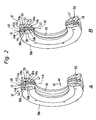
- Figur 2
- eine schematische perspektivische, teilweise geschnittene Ansicht zweier Gehäuseelemente mit dazwischen angeordnetem Dichtelement, wobei in Darstellung A der ungespannte und in Darstellung B der gespannte Zustand gezeigt ist,
- Figur 3
- eine perspektivische Ansicht auf ein zweites Gehäuseelement des Dichtungs-Gehäuses des erfindungsgemäßen Ventils,
- Figur 4
- einen Längsschnitt durch das Gehäuseelement von
Figur 3 , - Figur 5
- einen Längsschnitt durch ein erstes Gehäuseelement mit angeformtem Dichtelement und
- Figur 6
- in drei aufeinander folgenden Abbildungen A bis C einen Längsschnitt durch das erste und zweite Gehäuseelement samt Dichtungselement beim Zusammenfügen der Gehäuseelemente.
- Die
Figur 1 zeigt ein Ventil 11 als Bestandteil einer insgesamt mit Bezugsziffer 12 bezeichneten Ventilanordnung, die zusätzlich noch über einen bevorzugt plattenartig ausgebildeten Fluidverteiler 13 verfügt, auf dem das Ventil 11 lösbar, mittels geeigneten Befestigungsmitteln 14, befestigt ist. - Das Ventil 11 dient zur Steuerung von Fluidströmen und ist als Mehrwegeventil ausgeführt. Bei dem zu steuernden Medium handelt es sich insbesondere um Druckluft, wobei es sich allerdings auch um ein sonstiges gasförmiges oder hydraulisches Medium handeln kann.
- Das Ventil 11 verfügt über ein Ventilgehäuse 15, in dem wenigstens eine sich linear erstreckende, längliche Gehäuseausnehmung 16 vorgesehen ist. Umfangsseitig ist die Gehäuseausnehmung 16 von einer Gehäusewand 17 des Ventilgehäuses 15 begrenzt.
- Die Gehäusewand 17 und insbesondere das gesamte Ventilgehäuse 15 bestehen beim Ausführungsbeispiel aus Kunststoffmaterial. Die Herstellung erfolgt zweckmäßigerweise durch Spritzgießen, wobei ein Nachbearbeiten der die Gehäuseausnehmung 16 definierenden und nach radial innen orientierten Wandfläche 18 der Gehäusewand 17 nicht oder in nur geringem Maße erforderlich ist. Eine Bauform aus Metall wäre prinzipiell ebenfalls möglich.
- In die Gehäuseausnehmung 16 münden im Bereich der Wandfläche 18 an mehreren in der Längsrichtung der Gehäuseausnehmung 16 beabstandeten Stellen Ventilkanäle 19 ein. Diese durchsetzen die Gehäusewand 17 und bilden an ihrem äußeren Ende Anschlussöffnungen 20. Gemäß bevorzugtem Ausführungsbeispiel münden drei dieser Anschlussöffnungen zu einer außenliegenden Montagefläche 21 des Ventilgehäuses 15, mit der das Ventil 11 an einer Bestückungsfläche 22 des Fluidverteilers 13 angesetzt ist. In letzterem verlaufen mehrere Fluidverteilerkanäle 23, die zur Bestückungsfläche 22 ausmünden und dort mit den Anschlussöffnungen 20 paarweise kommunizieren.
- Gemäß dem Ausführungsbeispiel münden zwei weitere der Anschlussöffnungen 20 an einer der Montagefläche 21 insbesondere entgegengesetzten Anschlussfläche 24 des Ventilgehäuses 15 und sind dazu vorgesehen, das Anschließen nicht näher dargestellter Fluidleitungen zu ermöglichen, die zu einem anzusteuernden Verbraucher führen.
- Bei dem Ventil 11 des Ausführungsbeispiels handelt es sich um ein 4/2-Wegeventil. Es ist jedoch auch denkbar 3/2 oder 5/2-Wegeventile einzusetzen. Beim gezeigten 4/2-Wegeventil handelt es sich bei den zur Montagefläche 21 ausmündenden Ventilkanälen 19 um einen mittleren Speisekanal 19a, der axial von einem Entlüftungskanal 19b flankiert ist. Die beiden zur Anschlussfläche 24 führenden Ventilkanäle 19 sind Arbeitskanäle 19c und 19d.
- Auf dem Fluidverteiler 13 können mehrere Ventile 11 positioniert sein, die jeweils zuordnungsrichtig mit dem Fluidverteilerkanälen 23 verbunden sind.
- In der Gehäuseausnehmung 16 ist ein länglicher kolbenartiger Ventilschieber 25 angeordnet. Er verfügt über mehrere Steuerabschnitte 26 größeren Durchmessers, zwischen denen jeweils ein Steuerabschnitt 27 kleineren Durchmessers plaziert ist. Dem Ventilschieber 25 zugeordnete Betätigungsmittel ermöglichen ein axial verlagern und positionieren des ventilschiebers 25 in der Gehäuseausnehmung 16 relativ zum Ventilgehäuse 15.
- Die Betätigungsmittel enthalten beim Ausführungsbeispiel einen mit dem Ventilschieber 25 einenends in Wirkverbindung stehenden Antriebskolben 28. Dieser ist in einem als Betätigungsraum 29 bezeichneten Endabschnitt der Gehäuseausnehmung 16 unter Abdichtung verschiebbar geführt.
- Der auf der dem Ventilschieber 25 entgegengesetzten Seite des Antriebskolbens 28 liegende äußere Abschnitt 30 des Betätigungsraumes 29 kommuniziert auf nicht näher dargestellte Weise mit einem Steuerkanal 31, über den ein fluidisches Steuermedium wahlweise zugeführt oder abgeführt werden kann. Die entsprechende Steuerung übernimmt ein elektrisch aktivierbares Vorsteuerventil 32 das an das Ventilgehäuse 15 angebaut ist.
- Vergleichbare Betätigungsmittel können auch dem entgegengesetzten Ende des Ventilschiebers 25 zugeordnet sein. Abweichend hiervon findet sich dort beim Ausführungsbeispiel allerdings nur eine Rückstellfeder 33, die zwischen dem Ventilgehäuse 15 und dem Ventilschieber 25 wirksam ist und den Ventilschieber 25 ständig in Richtung zum Antriebskolben beaufschlagt.
- Im deaktivierten Zustand des Vorsteuerventils 32 nimmt der Ventilschieber 25, bedingt durch die Vorspannung der Rückstellfeder 33, die aus der Zeichnung ersichtliche erste Schaltstellung ein. Durch Aktivieren des Vorsteuerventils 32 wird der Antriebskolben 28 und somit der Ventilschieber 25 unter gleichzeitiger Komprimierung der Rückstellfeder 33 nach rechts in eine zweite Schaltstellung verlagert.
- Die Gehäuseausnehmung 16 ist an beiden Stirnseiten geschlossen. An wenigstens einer Stirnseite erfolgt der Verschluss durch einen lösbar am Ventilgehäuse 15 befestigten Verschlussdeckel 34. Im entfernten Zustand des Verschlussdeckels 34 ist die Gehäuseausnehmung 16 von der entsprechenden Stirnseite her zugänglich.
- In der Gehäuseausnehmung 16 befindet sich eine zwischen dem Ventilschieber 25 und der Gehäusewand 17 wirksame Dichtungseinrichtung 35. Sie sitzt koaxial zwischen der Wandfläche 18 und dem Ventilschieber 25, wobei sie von letzterem koaxial durchsetzt wird.
- Die Dichtungseinrichtung besitzt ein Dichtungsgehäuse 36, das seinerseits aus mindestens einer, vorzugsweise aus mehreren Dichtungseinheiten 37 aufgebaut ist, wobei gemäß dem Ausführungsbeispiel vier bzw. fünf Dichtungseinheiten 37 vorhanden sind.
- Wie insbesondere in
Figur 2 dargestellt, ist eine Dichtungseinheit 37 jeweils aus einem ersten, ringförmigen Gehäuseelement 38a und einem in axialer Richtung benachbarten zweiten, ringförmigen Gehäuseelement 38b aufgebaut, wobei zwischen dem ersten und zweiten Gehäuseelement 38a, 38b ein ringförmiges Dichtelement 39 fixiert ist. - Das Dichtelement 39 besteht aus einem Außenabschnitt 40 mit äußerem Dichtbereich 41 zur Abdichtung gegenüber der Gehäuseausnehmung 16 und einen Innenabschnitt 42 mit innerem Dichtbereich 43 zur Abdichtung gegenüber dem Ventilschieber 25.
- Im montierten Zustand der Dichtungseinrichtung 35 ist der Außenabschnitt 40 zwischen zwei zugeordneten Gehäuse-Außenabschnitten 44a, 44b der beiden Gehäuseelemente 38a, 38b fixiert, während dem Innenabschnitt 42 Gehäuse-Innenabschnitte 45a, 45b der beiden Gehäuseelemente 38a, 38b zugeordnet sind.
- An mindestens einem der Gehäuse-Außenabschnitte 44a, 44b, insbesondere am Gehäuse-Außenabschnitt 44b des zweiten Gehäuseelements 38b, das auch als Spannteil bezeichnet werden kann, befindet sich wenigstens ein Beaufschlagungsmittel 46, das den Außenabschnitt 40 des Dichtelements 39 derart beaufschlägt, dass der Außenabschnitt 40 und damit der äußere Dichtbereich 41 zur Erzielung einer Dichtwirkung radial nach außen gegen die Gehäusewand 17 gepresst wird.
- Das Beaufschlagungsmittel ist beispielhaft in Form eines am Gehäuse-Außenabschnitt 44b des zweiten Gehäuseelements 38b befindlichen, ringförmigen, zum zu beaufschlagenden Dichtelement 39 hin weisenden Wulstes 46 dargestellt. Der Wulst 46 kann beim Zusammenspannen der Gehäuseelemente in den Außenabschnitt 40 eindringen, so dass sich der Außenabschnitt nach radial außen verformt, womit eine Dichtwirkung gegenüber der Gehäuseausnehmung 16 erreicht wird. Es ist selbstverständlich auch möglich Beaufschlagungsmittel an beiden Gehäuseelementen 38a, 38b vorzusehen, beispielsweise zwei sich gegenüberliegende Wülste 46 vorzusehen, zwischen denen der Außenabschnitt 40 des Dichtelements 39 eingespannt ist. Eine Alternative ist, ein Beaufschlagungsmittel am ersten Gehäuseelement vorzusehen.
- Das Dichtelement 39 besitzt ferner wenigstens ein Entkopplungsmittel 47, das bewirkt, dass der Innenabschnitt 42 des Dichtelements 39 von den aus der Beaufschlagung des Außenabschnitts 40 resultierenden, nach radial innen gerichteten Kräften entkoppelt ist. Das Entkopplungsmittel ist beispielhaft anhand eines Übergangsabschnitts 47 dargestellt, der quer zum Außen- und zum Innenabschnitt 40, 41 des Dichtelements 39 angeordnet ist und einenends mit dem Außenabschnitt 40 und andernends mit dem Innenabschnitt 41 verbunden ist. Durch den Übergangsabschnitt 47 wird erreicht, dass die Außenabschnitts-Radialebene 48 des Außenabschnitts 40, die den äußeren Dichtbereich enthält axial versetzt zur Innenabschnitts-Radialebene 49 des Innenabschnitts, die den inneren Dichtbereich enthält, angeordnet ist. Eine Beaufschlagung des Außenabschnitts und eine insbesondere damit verbundene Bewegung desselbigen nach radial innen, wird also durch den Übergangsabschnitt 47 aufgefangen und nicht auf den Innenabschnitt 42 übertragen, so dass dort keine Bewegung nach radial innen erfolgt. Eine Bewegung des Dichtelements 39 nach radial innen ist unerwünscht, da dadurch zusätzlich Reibung zwischen dem inneren Dichtbereich 43 und dem Ventilschieber 25 entstehen könnte, was zu erhöhtem Verschleiß des Dichtelements 39 und/oder zu einer Beeinträchtigung der Schaltfunktion des Ventils 11 führen könnte.
- Das Dichtelement 39 hat insgesamt die Gestalt eines abgesetzten bzw. abgestuften Dichtungsrings, wobei Außenabschnitt, Übergangsabschnitt und Innenabschnitt 40, 42, 47 einstückig miteinander verbunden sind und durch einen einzigen Dichtelement-Herstellungsprozeß hergestellt werden können. Das Dichtelement 39 besteht aus einem relativ weichen Elastomermaterial, das vorzugsweise weicher ist, als der Wulst 46 am zweiten Gehäuseelement 38b, so dass dieser beim Zusammenspannen der Gehäuseelemente 38a, 38b in das weiche Elastomermaterial eindringen und den Außenabschnitt 40 verformen kann, so dass der äußere Dichtbereich 41 gegen die Wandfläche 18 der Gehäusewand 17 gepresst wird. Als Elastomermaterial kann beispielsweise ein thermoplastisches Elastomer eingesetzt werden.
- Während das zweite Gehäuseelement 38b mit seinem Wulst 46 zum Beaufschlagen bzw. Spannen des Dichtelements 39 dient, ist das erste Gehäuseelement 38a, das auch als Trägerteil bezeichnet werden kann, zum Tragen des Dichtelements 39 bestimmt. Die Befestigung des Dichtelements 39 am ersten Gehäuseelement 38a erfolgt über Haltemittel 50, die einen Formschluss zwischen Dichtelement 39 und erstem Gehäuseelement 38a bilden, so dass das Dichtelement 39 entgegen einer Montagerichtung 51 nicht wieder vom ersten Gehäuseelement 38a abgezogen werden kann.
- Die Haltemittel 50 werden vom Dichtelement 39 selbst gebildet, insbesondere werden sie bei der Herstellung des Dichtelements 39 mit angeformt. Zweckmäßigerweise ist das erste Gehäuseelement 38a derart ausgebildet, dass das Dichtelement 39 daran angeformt, vorzugsweise mittels eines Spritzprozesses, beispielsweise mittels eines Elastomer-Spritzgießverfahrens daran angespritzt werden kann.
- Wie insbesondere in
Figur 5 dargestellt besitzt das erste Gehäuseelement 38a an seiner dem Dichtelement 39 gegenüberliegenden Rückseite eine ringförmige, umlaufende Nut 52, an deren Nutgrund Öffnungen 53 vorgesehen sind, die an der Vorderseite des ersten Gehäuseelements 38a ausmünden. Die ringförmige Nut 52 und die Öffnungen 53, die vorzugsweise als Bohrungen mit kreisrundem Querschnitt ausgebildet sind, dienen zur Aufnahme von Verankerungspartien 54 der Haltemittel 50. Es ist beispielsweise möglich das Dichtelement 39 von der Rückseite des ersten Gehäuseelements 38a her zunächst die ringförmige Nut 52 füllend anzuspritzen, so dass plastifiziertes Dichtelement-Material über die Öffnungen 53 zur Innenseite gelangt und dort ein in einer die Gestalt des Dichtelements 39 vorgebenden Negativform aufgenommen wird und dort zu seiner endgültigen Gestalt erstarrt. - Die einzelnen Dichtungseinheiten 37 der Dichtungseinrichtung 35 sind in regelmäßigen Abständen entlang der Gehäuseausnehmung 16 des Ventilgehäuses 15 angeordnet. Dieser regelmäßige Abstand wird durch Abstandshalter bzw. Distanzelemente 55 erreicht, die vorzugsweise an der dem Dichtelement39 abgewandten Außenseite des zweiten Gehäuseelements 38b befestigt sind.
- Wie in
Figur 6 in drei aufeinanderfolgenden Schritten A bis C dargestellt erfolgt die Montage der Dichtungseinrichtung 35 gemäß dem gezeigten Ausführungsbeispiel von der Seite, an dem sich das Vorsteuerventil 32 befindet, also in einer Montagerichtung 51 von links nach rechts. Dabei wird zunächst ein erstes Gehäuseelement 38a samt daran befestigtem Dichtelement 39 in die Gehäuseausnehmung 16 eingeschoben, bis es seinen vorbestimmten Platz entlang der Gehäuseausnehmung 16 erreicht, der im gezeigten Ausführungsbeispiel durch eine Abstufung 56 am Verschlußdeckel 34 gebildet wird. Beim Einschieben des ersten Gehäuseelements 38a mitsamt dem Dichtelement 39 werden die seitlich in die Gehäuseausnehmung 16 einmündenden Ventilkanäle 19a bis 19d passiert. Bei herkömmlichen Dichtungseinrichtungen deren Dichtungselemente bereits beim Montieren press an der Gehäusewand 17 anliegen, entspannen sich die Dichtungselemente, wenn sie über die Mündungen der Ventilkanäle gedrückt werden. Dies hat zur Folge, dass sich das elastische Gummi-Dichtelementmaterial etwas in die Mündungen hineinverformt. Wird die Dichtungseinrichtung 35 nun in Montagerichtung 51 weitergedrückt bleibt der in die Mündung hineinverformte Abschnitt des Dichtelements am Rand der Mündung hängen, was zur Beschädigung des Dichtelements führen kann. Beim erfindungsgemäßen Ventil 11 ist das Dichtelement 39 während des Montierens nicht unter Spannung, das heißt, es wird noch nicht gegen die Wandfläche 18 der Gehäuseausnehmung 6 gepreßt. Die Dichtwirkung wird erst mit dem Zusammenspannen der beiden Gehäuseelemente 38a, 38b erzeugt. - Folglich verformt sich das zu montierende Dichtelement 39 auch nicht in die Kanalmündungen der zu passierenden Ventilkanäle hinein, was den zuvor beschriebenen Effekt verhindert.
- Als nächstes wird das dazugehörige, zweite Gehäuseelement 38b eingeschoben und mit dem ersten Gehäuseelement zusammengespannt, wobei der am Gehäuse-Aussenabschnitt 44b des zweiten Gehäuseelements 38b befindliche Wulst 46 in den Außenabschnitt 40 des Dichtelements 39 eingedrückt wird, so dass sich der Außenabschnitt 40 und somit der äußere Dichtbereich 41 radial außen verformt und eine Dichtwirkung gegenüber der Wandfläche 18 der Gehäusewand 17 erzielt wird. Gleichzeitig verhindert der zwischen dem Außenabschnitt 40 und dem Innenabschnitt 42 ausgebildete, quer zu diesen beiden Abschnitten liegende Übergangsabschnitt 47, dass der Innenabschnitt 42 mitverformt wird. An der dem Dichtelement 39 abgewandten Außenseite des zweiten Gehäuseelements 38b befinden sich über den Umfang des zweiten Gehäuseelements 38b verteilt mehrere, insbesondere drei Abstandshalter 55, die die Lage der nächsten, in Montagerichtung 51 davor liegenden Dichtungseinheit 37 festlegen. Als nächstes wird dann wiederum ein erstes Gehäuseelement samt Dichtelement 39 eingeschoben, bis es an den Abstandshalter anstößt. So können nach und nach mehrere, im Ausführungsbeispiel fünf, Dichtungseinheiten 37 eingeschoben werden. Bei der letzten Dichtungseinheit 37 besitzt das zweite Gehäuseelement 38b keinen Abstandshalter 55 mehr, sondern zweckmäßigerweise Verzahnungsmittel 57, mit der diese Dichtungseinheit 37 in der Gehäuseausnehmung 16 festgelegt und die gesamte Dichtungseinrichtung 35 gegen Herausziehen entgegen der Montagerichtung 51 verrastet wird.
Claims (14)
- Ventil, mit einem Ventilgehäuse (15), das eine zur Aufnahme eines Ventilschiebers (25) vorgesehene, umfangsseitig von einer Gehäusewand (17) begrenzte längliche Gehäuseausnehmung (16) aufweist, in die seitlich mindestens ein Ventilkanal (19) einmündet und in der eine vom Ventilschieber (25) durchsetzte Dichtungseinrichtung (35) angeordnet ist, die ein Dichtungs-Gehäuse (36) besitzt, das wenigstens ein ringförmiges Dichtelement (39) aufweist, das einen Außenabschnitt (40) mit äußerem Dichtbereich (41) zur Abdichtung gegenüber der Gehäuseausnehmung (16) und einen Innenabschnitt (42) mit innerem Dichtbereich (43) zur Abdichtung gegenüber dem Ventilschieber (25) besitzt, wobei das Dichtungs-Gehäuse (36) im Bereich des Dichtelementes (39) zwei das Dichtelement (39) zwischen sich fixierende ringförmigen Gehäuseelemente (38a, 38b) aufweist, wobei wenigstens eines der Gehäuseelemente (38a, 38b) an der dem Außenabschnitt (40) axial zugeordneten Seite über wenigstens ein Beaufschlagungsmittel (46) verfügt, das beim Zusammenspannen der Gehäuseelemente (38a, 38b) lokal den Außenabschnitt (40) derart beaufschlägt, dass der Außenabschnitt (40) zur Erzielung einer Dichtwirkung radial nach außen gegen die Gehäusewand (17) pressbar ist, wobei der Außenabschnitt (40) eine den äußeren Dichtbereich (41) enthaltende Außenabschnitts-Radialebene (48) und der Innenabschnitt (42) eine den inneren Dichtbereich (43) enthaltende Innenabschnitts-Radialebene (49) aufweist, und wobei wenigstens ein Entkopplungsmittel zur Entkopplung des Innenabschnitts (42) von den aus der Beaufschlagung des Außenabschnitts (40) resultierenden, nach radial innen gerichteten Kräften in Form eines zwischen dem Außenabschnitt (40) und dem Innenabschnitt (42) befindlichen, einerseits mit dem Außenabschnitt (40) und andererseits mit dem Innenabschnitt (42) verbundenen, quer zum Außen- und zum Innenabschnitt (40, 42) ausgerichteten Übergangsabschnitt (47) vorgesehen ist, der bewirkt, dass die Außenabschnitts-Radialebene (48) axial versetzt zur Innenabschnitts-Radialebene (49) angeordnet ist, und wobei die Gehäuseelemente (38a, 38b) korrespondierend zum Übergangsabschnitt (47) des Dichtelements (39) verlaufende Gehäuse-Übergangsabschnitte (58a, 58b) aufweisen, wobei im montierten Zustand der Dichtungseinrichtung (35) der Übergangsabschnitt (47) des Dichtelements (39) zwischen den Gehäuse-Übergangsabschnitten (58a, 58b) angeordnet ist, dadurch gekennzeichnet, dass radial zwischen dem Übergangsabschnitt (47) des Dichtelements (39) und dem den Übergangsabschnitt radial innen flankierenden Gehäuse-Übergangsabschnitt (58a, 58b) im montierten Zustand der Dichtungseinrichtung (35) ein Freiraum (59) ausgebildet ist.
- Ventil nach Anspruch 1, dadurch gekennzeichnet, dass der Übergangsabschnitt (47) im wesentlichen senkrecht zum Außen- und zum Innenabschnitt (40, 42) ausgerichtet ist.
- Ventil nach Anspruch 1 oder 2, dadurch gekennzeichnet, dass Außenabschnitt (40), Übergangsabschnitt (47) und Innenabschnitt (42) einstückig miteinander verbunden sind.
- Ventil nach einem der vorhergehenden Ansprüche, dadurch gekennzeichnet, dass Außenabschnitt (40), Übergangsabschnitt (47) und Innenabschnitt (42) aus dem selben Material hergestellt sind, insbesondere aus Elastomermaterial.
- Ventil nach Anspruch 4, dadurch gekennzeichnet, dass als Elastomermaterial ein thermoplastisches Elastomer vorgesehen ist.
- Ventil nach einem der vorhergehenden Ansprüche, dadurch gekennzeichnet, dass wenigstens ein erstes Gehäuseelement (38a) vorgesehen ist, das mittels Haltemitteln (50) mit dem Dichtelement (39) verbunden ist und wenigstens ein zweites Gehäuseelement (38b) vorgesehen ist, das über das Beaufschlagungsmittel (46) zur Beaufschlagung des Außenabschnitts (40) des Dichtelements (39) verfügt.
- Ventil nach Anspruch 6, dadurch gekennzeichnet, dass als Beaufschlagungsmittel ein ringförmiger Wulst (46) vorgesehen ist, der von der dem Außenabschnitt (40) des Dichtelements (39) zugeordneten Seite des zweiten Gehäuseelements (38b) axial hervorsteht.
- Ventil nach Anspruch 7, dadurch gekennzeichnet, dass der Wulst (46) aus einem im vergleich zum Material des Außenabschnitts (40) härteren Material hergestellt ist.
- Ventil nach einem der Ansprüche 6 bis 8, dadurch gekennzeichnet, dass die Haltemittel (50) einen Formschluss zwischen dem ersten Gehäuseelement (38a) und dem zu haltenden Dichtelement (39) bilden.
- Ventil nach einem der Ansprüche 6 bis 9, dadurch gekennzeichnet, dass die Haltemittel (50) vom Dichtelement (39) selbst gebildet sind, vorzugsweise an dieses angeformt sind.
- Ventil nach einem der Ansprüche 6 bis 10, dadurch gekennzeichnet, dass das erste Gehäuseelement (38a) an seiner dem Dichtelement abgewandten Rückseite eine ringförmige Nut (52) zur Aufnahme einer korrespondierend dazu ausgebildeten Verankerungspartie (54) des zugeordneten Haltemittels (50) aufweist, wobei die Nut (52) über in axialer Richtung verlaufende, insbesondere in regelmäßigen Abständen über den Umfang der Nut (52) verteilte Öffnungen (53) mit der Vorderseite des Gehäuseelements (38a) verbunden ist, die von den Haltemitteln (50) durchgriffen werden.
- Ventil nach einem der vorhergehenden Ansprüche, dadurch gekennzeichnet, dass die ersten und/oder zweiten Gehäuseelemente (38a, 38b) an ihren dem Dichtelement (39) abgewandten Rückseiten über Abstandshalter (55) mit benachbarten weiteren ersten oder zweiten Gehäuseelementen (38a, 38b) gekoppelt sind, wobei vorzugsweise das erste Gehäuseelement (38a) mit einem benachbarten weitern zweiten und das zweite Gehäuseelement (38b) mit einem benachbarten weiteren ersten Gehäuseelement (38a) gekoppelt ist.
- Ventil nach Anspruch 12, dadurch gekennzeichnet, dass die Abstandshalter (50) am zweiten Gehäuseelement (38b) befestigt, insbesondere daran angeformt sind.
- Ventil nach einem der vorhergehenden Ansprüche, dadurch gekennzeichnet, dass die ersten und zweiten Gehäuseelemente (38a, 38b) aus dem selben Material hergestellt sind, insbesondere aus Polymermaterial.
Applications Claiming Priority (2)
| Application Number | Priority Date | Filing Date | Title |
|---|---|---|---|
| DE102004007091 | 2004-02-13 | ||
| DE102004007091A DE102004007091B3 (de) | 2004-02-13 | 2004-02-13 | Ventil |
Publications (2)
| Publication Number | Publication Date |
|---|---|
| EP1564458A1 EP1564458A1 (de) | 2005-08-17 |
| EP1564458B1 true EP1564458B1 (de) | 2008-09-24 |
Family
ID=34684036
Family Applications (1)
| Application Number | Title | Priority Date | Filing Date |
|---|---|---|---|
| EP05001872A Expired - Lifetime EP1564458B1 (de) | 2004-02-13 | 2005-01-29 | Ventil |
Country Status (4)
| Country | Link |
|---|---|
| EP (1) | EP1564458B1 (de) |
| AT (1) | ATE409296T1 (de) |
| DE (2) | DE102004007091B3 (de) |
| ES (1) | ES2311886T3 (de) |
Families Citing this family (1)
| Publication number | Priority date | Publication date | Assignee | Title |
|---|---|---|---|---|
| DE102008032716B4 (de) * | 2008-07-11 | 2011-03-31 | Knorr-Bremse Systeme für Nutzfahrzeuge GmbH | Ventil mit hoher mittlerer Betriebsdauer |
Family Cites Families (6)
| Publication number | Priority date | Publication date | Assignee | Title |
|---|---|---|---|---|
| DE1287878B (de) * | 1969-01-23 | Hoerbiger Ventilwerke Ag, Wien | Einrichtung zum Abdichten von axial verschiebbaren Steuerkolben, Stangen u.dgl | |
| US2892644A (en) * | 1954-06-18 | 1959-06-30 | Int Basic Economy Corp | Packing means for plunger valves |
| US3451430A (en) * | 1966-11-16 | 1969-06-24 | Lloyd D Cowdin | Fluid control valve |
| DE3043871A1 (de) * | 1980-11-21 | 1982-07-08 | Wabco Steuerungstechnik GmbH & Co, 3000 Hannover | Mehrwegeventil |
| DE3240552C2 (de) * | 1982-11-03 | 1986-08-28 | Prädifa Präzisions-Dichtungs-Fabrik GmbH, 7120 Bietigheim-Bissingen | Schieberventildichtung |
| DE4101049C2 (de) * | 1991-01-16 | 1997-08-21 | Miele & Cie | Teleskopierbares Saugrohr eines Staubsaugers |
-
2004
- 2004-02-13 DE DE102004007091A patent/DE102004007091B3/de not_active Expired - Fee Related
-
2005
- 2005-01-29 EP EP05001872A patent/EP1564458B1/de not_active Expired - Lifetime
- 2005-01-29 DE DE502005005438T patent/DE502005005438D1/de not_active Expired - Lifetime
- 2005-01-29 ES ES05001872T patent/ES2311886T3/es not_active Expired - Lifetime
- 2005-01-29 AT AT05001872T patent/ATE409296T1/de not_active IP Right Cessation
Also Published As
| Publication number | Publication date |
|---|---|
| DE102004007091B3 (de) | 2005-07-28 |
| EP1564458A1 (de) | 2005-08-17 |
| DE502005005438D1 (de) | 2008-11-06 |
| ATE409296T1 (de) | 2008-10-15 |
| ES2311886T3 (es) | 2009-02-16 |
Similar Documents
| Publication | Publication Date | Title |
|---|---|---|
| DE69708991T2 (de) | Wechselventil mit Mitteln zur Vermeidung von Gegenstrom | |
| DE3831554C2 (de) | Drosselrückschlagventil | |
| EP0279930B1 (de) | Beatmungsvorrichtung für einen Federspeicherbremszylinder | |
| DE102013208459A1 (de) | Geberzylinder | |
| DE2651133C3 (de) | Dosierventil für Schmiersysteme | |
| EP3067598A1 (de) | Mehrwegeventil | |
| EP2924327B1 (de) | Mehrwegeventil | |
| DE102005003982A1 (de) | Pneumatisches Wegeventil mit einem Ventilschieber | |
| DE102019211004A1 (de) | Ventil | |
| EP1564458B1 (de) | Ventil | |
| EP4056880A1 (de) | Drehkolbenabdichtung | |
| DE102019200784B4 (de) | Rückschlagventil | |
| DE2854572A1 (de) | Durch fluessigkeitsdruck betaetigbares pilotventil | |
| DE102018114238B4 (de) | Gesteuertes Bremsmagnetventil | |
| DE2449443A1 (de) | Rueckschlagventil | |
| DE102015003062A1 (de) | Mehrwegeventil | |
| DE202005016282U1 (de) | Ventilglied und damit ausgestattetes Ventil | |
| EP1572512A1 (de) | Kolben für eine hydraulische bremsanlage und damit ausgestatteter hauptzylinder | |
| DE102006018088A1 (de) | Führungsmechanismus für Zylindervorrichtung | |
| DE102005048593A1 (de) | Kunststoffleitung, insbesondere hydraulische Kupplungsdruck-Übertragungsleitung für ein Kraftfahrzeug, und Verfahren zum Herstellen einer Kunststoffleitung | |
| DE102009056496A1 (de) | Drosselventil | |
| DE4119402A1 (de) | Schieberventil | |
| WO2022171463A1 (de) | Baugruppe für eine fluidgefüllte kolben-zylinder-einheit sowie fluidgefüllte kolben-zylinder-einheit mit einer derartigen baugruppe | |
| EP1517072B1 (de) | Ventil | |
| DE102019133667A1 (de) | Vorrichtung zur Regelung von Drücken eines Strömungsmittels mit einem Ven-til |
Legal Events
| Date | Code | Title | Description |
|---|---|---|---|
| PUAI | Public reference made under article 153(3) epc to a published international application that has entered the european phase |
Free format text: ORIGINAL CODE: 0009012 |
|
| AK | Designated contracting states |
Kind code of ref document: A1 Designated state(s): AT BE BG CH CY CZ DE DK EE ES FI FR GB GR HU IE IS IT LI LT LU MC NL PL PT RO SE SI SK TR |
|
| AX | Request for extension of the european patent |
Extension state: AL BA HR LV MK YU |
|
| 17P | Request for examination filed |
Effective date: 20050707 |
|
| AKX | Designation fees paid |
Designated state(s): AT BE BG CH CY CZ DE DK EE ES FI FR GB GR HU IE IS IT LI LT LU MC NL PL PT RO SE SI SK TR |
|
| GRAP | Despatch of communication of intention to grant a patent |
Free format text: ORIGINAL CODE: EPIDOSNIGR1 |
|
| RAP1 | Party data changed (applicant data changed or rights of an application transferred) |
Owner name: FESTO AG & CO. KG |
|
| GRAS | Grant fee paid |
Free format text: ORIGINAL CODE: EPIDOSNIGR3 |
|
| GRAA | (expected) grant |
Free format text: ORIGINAL CODE: 0009210 |
|
| AK | Designated contracting states |
Kind code of ref document: B1 Designated state(s): AT BE BG CH CY CZ DE DK EE ES FI FR GB GR HU IE IS IT LI LT LU MC NL PL PT RO SE SI SK TR |
|
| REG | Reference to a national code |
Ref country code: GB Ref legal event code: FG4D Free format text: NOT ENGLISH |
|
| REG | Reference to a national code |
Ref country code: CH Ref legal event code: EP |
|
| REG | Reference to a national code |
Ref country code: IE Ref legal event code: FG4D Free format text: LANGUAGE OF EP DOCUMENT: GERMAN |
|
| REF | Corresponds to: |
Ref document number: 502005005438 Country of ref document: DE Date of ref document: 20081106 Kind code of ref document: P |
|
| PG25 | Lapsed in a contracting state [announced via postgrant information from national office to epo] |
Ref country code: LT Free format text: LAPSE BECAUSE OF FAILURE TO SUBMIT A TRANSLATION OF THE DESCRIPTION OR TO PAY THE FEE WITHIN THE PRESCRIBED TIME-LIMIT Effective date: 20080924 |
|
| REG | Reference to a national code |
Ref country code: ES Ref legal event code: FG2A Ref document number: 2311886 Country of ref document: ES Kind code of ref document: T3 |
|
| PG25 | Lapsed in a contracting state [announced via postgrant information from national office to epo] |
Ref country code: SI Free format text: LAPSE BECAUSE OF FAILURE TO SUBMIT A TRANSLATION OF THE DESCRIPTION OR TO PAY THE FEE WITHIN THE PRESCRIBED TIME-LIMIT Effective date: 20080924 Ref country code: FI Free format text: LAPSE BECAUSE OF FAILURE TO SUBMIT A TRANSLATION OF THE DESCRIPTION OR TO PAY THE FEE WITHIN THE PRESCRIBED TIME-LIMIT Effective date: 20080924 |
|
| NLV1 | Nl: lapsed or annulled due to failure to fulfill the requirements of art. 29p and 29m of the patents act | ||
| REG | Reference to a national code |
Ref country code: IE Ref legal event code: FD4D |
|
| PG25 | Lapsed in a contracting state [announced via postgrant information from national office to epo] |
Ref country code: BG Free format text: LAPSE BECAUSE OF FAILURE TO SUBMIT A TRANSLATION OF THE DESCRIPTION OR TO PAY THE FEE WITHIN THE PRESCRIBED TIME-LIMIT Effective date: 20081224 |
|
| PG25 | Lapsed in a contracting state [announced via postgrant information from national office to epo] |
Ref country code: SK Free format text: LAPSE BECAUSE OF FAILURE TO SUBMIT A TRANSLATION OF THE DESCRIPTION OR TO PAY THE FEE WITHIN THE PRESCRIBED TIME-LIMIT Effective date: 20080924 Ref country code: RO Free format text: LAPSE BECAUSE OF FAILURE TO SUBMIT A TRANSLATION OF THE DESCRIPTION OR TO PAY THE FEE WITHIN THE PRESCRIBED TIME-LIMIT Effective date: 20080924 Ref country code: PT Free format text: LAPSE BECAUSE OF FAILURE TO SUBMIT A TRANSLATION OF THE DESCRIPTION OR TO PAY THE FEE WITHIN THE PRESCRIBED TIME-LIMIT Effective date: 20090224 Ref country code: NL Free format text: LAPSE BECAUSE OF FAILURE TO SUBMIT A TRANSLATION OF THE DESCRIPTION OR TO PAY THE FEE WITHIN THE PRESCRIBED TIME-LIMIT Effective date: 20080924 Ref country code: IS Free format text: LAPSE BECAUSE OF FAILURE TO SUBMIT A TRANSLATION OF THE DESCRIPTION OR TO PAY THE FEE WITHIN THE PRESCRIBED TIME-LIMIT Effective date: 20090124 Ref country code: CZ Free format text: LAPSE BECAUSE OF FAILURE TO SUBMIT A TRANSLATION OF THE DESCRIPTION OR TO PAY THE FEE WITHIN THE PRESCRIBED TIME-LIMIT Effective date: 20080924 |
|
| PG25 | Lapsed in a contracting state [announced via postgrant information from national office to epo] |
Ref country code: IE Free format text: LAPSE BECAUSE OF FAILURE TO SUBMIT A TRANSLATION OF THE DESCRIPTION OR TO PAY THE FEE WITHIN THE PRESCRIBED TIME-LIMIT Effective date: 20080924 Ref country code: EE Free format text: LAPSE BECAUSE OF FAILURE TO SUBMIT A TRANSLATION OF THE DESCRIPTION OR TO PAY THE FEE WITHIN THE PRESCRIBED TIME-LIMIT Effective date: 20080924 Ref country code: DK Free format text: LAPSE BECAUSE OF FAILURE TO SUBMIT A TRANSLATION OF THE DESCRIPTION OR TO PAY THE FEE WITHIN THE PRESCRIBED TIME-LIMIT Effective date: 20080924 |
|
| PLBE | No opposition filed within time limit |
Free format text: ORIGINAL CODE: 0009261 |
|
| STAA | Information on the status of an ep patent application or granted ep patent |
Free format text: STATUS: NO OPPOSITION FILED WITHIN TIME LIMIT |
|
| PG25 | Lapsed in a contracting state [announced via postgrant information from national office to epo] |
Ref country code: MC Free format text: LAPSE BECAUSE OF NON-PAYMENT OF DUE FEES Effective date: 20090131 |
|
| REG | Reference to a national code |
Ref country code: CH Ref legal event code: PL |
|
| 26N | No opposition filed |
Effective date: 20090625 |
|
| PG25 | Lapsed in a contracting state [announced via postgrant information from national office to epo] |
Ref country code: LI Free format text: LAPSE BECAUSE OF NON-PAYMENT OF DUE FEES Effective date: 20090131 Ref country code: CH Free format text: LAPSE BECAUSE OF NON-PAYMENT OF DUE FEES Effective date: 20090131 |
|
| PG25 | Lapsed in a contracting state [announced via postgrant information from national office to epo] |
Ref country code: SE Free format text: LAPSE BECAUSE OF FAILURE TO SUBMIT A TRANSLATION OF THE DESCRIPTION OR TO PAY THE FEE WITHIN THE PRESCRIBED TIME-LIMIT Effective date: 20081224 |
|
| PG25 | Lapsed in a contracting state [announced via postgrant information from national office to epo] |
Ref country code: BE Free format text: LAPSE BECAUSE OF NON-PAYMENT OF DUE FEES Effective date: 20090131 |
|
| PG25 | Lapsed in a contracting state [announced via postgrant information from national office to epo] |
Ref country code: PL Free format text: LAPSE BECAUSE OF FAILURE TO SUBMIT A TRANSLATION OF THE DESCRIPTION OR TO PAY THE FEE WITHIN THE PRESCRIBED TIME-LIMIT Effective date: 20080924 |
|
| PG25 | Lapsed in a contracting state [announced via postgrant information from national office to epo] |
Ref country code: AT Free format text: LAPSE BECAUSE OF NON-PAYMENT OF DUE FEES Effective date: 20090129 |
|
| PG25 | Lapsed in a contracting state [announced via postgrant information from national office to epo] |
Ref country code: GR Free format text: LAPSE BECAUSE OF FAILURE TO SUBMIT A TRANSLATION OF THE DESCRIPTION OR TO PAY THE FEE WITHIN THE PRESCRIBED TIME-LIMIT Effective date: 20081225 |
|
| PG25 | Lapsed in a contracting state [announced via postgrant information from national office to epo] |
Ref country code: LU Free format text: LAPSE BECAUSE OF NON-PAYMENT OF DUE FEES Effective date: 20090129 |
|
| PG25 | Lapsed in a contracting state [announced via postgrant information from national office to epo] |
Ref country code: HU Free format text: LAPSE BECAUSE OF FAILURE TO SUBMIT A TRANSLATION OF THE DESCRIPTION OR TO PAY THE FEE WITHIN THE PRESCRIBED TIME-LIMIT Effective date: 20090325 |
|
| PG25 | Lapsed in a contracting state [announced via postgrant information from national office to epo] |
Ref country code: TR Free format text: LAPSE BECAUSE OF FAILURE TO SUBMIT A TRANSLATION OF THE DESCRIPTION OR TO PAY THE FEE WITHIN THE PRESCRIBED TIME-LIMIT Effective date: 20080924 |
|
| PG25 | Lapsed in a contracting state [announced via postgrant information from national office to epo] |
Ref country code: CY Free format text: LAPSE BECAUSE OF FAILURE TO SUBMIT A TRANSLATION OF THE DESCRIPTION OR TO PAY THE FEE WITHIN THE PRESCRIBED TIME-LIMIT Effective date: 20080924 |
|
| PGFP | Annual fee paid to national office [announced via postgrant information from national office to epo] |
Ref country code: ES Payment date: 20150122 Year of fee payment: 11 |
|
| REG | Reference to a national code |
Ref country code: FR Ref legal event code: PLFP Year of fee payment: 12 |
|
| REG | Reference to a national code |
Ref country code: FR Ref legal event code: PLFP Year of fee payment: 13 |
|
| PGFP | Annual fee paid to national office [announced via postgrant information from national office to epo] |
Ref country code: GB Payment date: 20161222 Year of fee payment: 13 |
|
| REG | Reference to a national code |
Ref country code: ES Ref legal event code: FD2A Effective date: 20170227 |
|
| PG25 | Lapsed in a contracting state [announced via postgrant information from national office to epo] |
Ref country code: ES Free format text: LAPSE BECAUSE OF NON-PAYMENT OF DUE FEES Effective date: 20160130 |
|
| REG | Reference to a national code |
Ref country code: FR Ref legal event code: PLFP Year of fee payment: 14 |
|
| GBPC | Gb: european patent ceased through non-payment of renewal fee |
Effective date: 20180129 |
|
| PG25 | Lapsed in a contracting state [announced via postgrant information from national office to epo] |
Ref country code: GB Free format text: LAPSE BECAUSE OF NON-PAYMENT OF DUE FEES Effective date: 20180129 |
|
| PGFP | Annual fee paid to national office [announced via postgrant information from national office to epo] |
Ref country code: IT Payment date: 20190121 Year of fee payment: 15 Ref country code: FR Payment date: 20190122 Year of fee payment: 15 |
|
| REG | Reference to a national code |
Ref country code: DE Ref legal event code: R082 Ref document number: 502005005438 Country of ref document: DE Representative=s name: PATENTANWAELTE MAGENBAUER & KOLLEGEN PARTNERSC, DE Ref country code: DE Ref legal event code: R081 Ref document number: 502005005438 Country of ref document: DE Owner name: FESTO AG & CO. KG, DE Free format text: FORMER OWNER: FESTO AG & CO. KG, 73734 ESSLINGEN, DE Ref country code: DE Ref legal event code: R081 Ref document number: 502005005438 Country of ref document: DE Owner name: FESTO SE & CO. KG, DE Free format text: FORMER OWNER: FESTO AG & CO. KG, 73734 ESSLINGEN, DE |
|
| PGFP | Annual fee paid to national office [announced via postgrant information from national office to epo] |
Ref country code: DE Payment date: 20191214 Year of fee payment: 16 |
|
| PG25 | Lapsed in a contracting state [announced via postgrant information from national office to epo] |
Ref country code: FR Free format text: LAPSE BECAUSE OF NON-PAYMENT OF DUE FEES Effective date: 20200131 |
|
| PG25 | Lapsed in a contracting state [announced via postgrant information from national office to epo] |
Ref country code: IT Free format text: LAPSE BECAUSE OF NON-PAYMENT OF DUE FEES Effective date: 20200129 |
|
| REG | Reference to a national code |
Ref country code: DE Ref legal event code: R119 Ref document number: 502005005438 Country of ref document: DE |
|
| PG25 | Lapsed in a contracting state [announced via postgrant information from national office to epo] |
Ref country code: DE Free format text: LAPSE BECAUSE OF NON-PAYMENT OF DUE FEES Effective date: 20210803 |