EP1564458B1 - Soupape - Google Patents
Soupape Download PDFInfo
- Publication number
- EP1564458B1 EP1564458B1 EP05001872A EP05001872A EP1564458B1 EP 1564458 B1 EP1564458 B1 EP 1564458B1 EP 05001872 A EP05001872 A EP 05001872A EP 05001872 A EP05001872 A EP 05001872A EP 1564458 B1 EP1564458 B1 EP 1564458B1
- Authority
- EP
- European Patent Office
- Prior art keywords
- housing
- section
- sealing
- valve
- sealing element
- Prior art date
- Legal status (The legal status is an assumption and is not a legal conclusion. Google has not performed a legal analysis and makes no representation as to the accuracy of the status listed.)
- Expired - Lifetime
Links
- 238000007789 sealing Methods 0.000 claims abstract description 159
- 230000000694 effects Effects 0.000 claims abstract description 11
- 230000007704 transition Effects 0.000 claims description 26
- 239000000463 material Substances 0.000 claims description 14
- 125000006850 spacer group Chemical group 0.000 claims description 14
- 239000011324 bead Substances 0.000 claims description 12
- 229920001971 elastomer Polymers 0.000 claims description 5
- 239000000806 elastomer Substances 0.000 claims description 4
- 238000004873 anchoring Methods 0.000 claims description 3
- 229920002725 thermoplastic elastomer Polymers 0.000 claims description 3
- 230000002093 peripheral effect Effects 0.000 claims 1
- 239000002861 polymer material Substances 0.000 claims 1
- 238000003825 pressing Methods 0.000 claims 1
- 239000012530 fluid Substances 0.000 description 7
- 239000013536 elastomeric material Substances 0.000 description 4
- 238000004519 manufacturing process Methods 0.000 description 4
- 238000011161 development Methods 0.000 description 2
- 230000018109 developmental process Effects 0.000 description 2
- 238000009826 distribution Methods 0.000 description 2
- 238000002347 injection Methods 0.000 description 2
- 239000007924 injection Substances 0.000 description 2
- 238000001746 injection moulding Methods 0.000 description 2
- 229910052751 metal Inorganic materials 0.000 description 2
- 239000002184 metal Substances 0.000 description 2
- 238000000034 method Methods 0.000 description 2
- 230000003068 static effect Effects 0.000 description 2
- 230000003213 activating effect Effects 0.000 description 1
- 230000006835 compression Effects 0.000 description 1
- 238000007906 compression Methods 0.000 description 1
- 230000006735 deficit Effects 0.000 description 1
- 238000013461 design Methods 0.000 description 1
- 238000006073 displacement reaction Methods 0.000 description 1
- 238000003780 insertion Methods 0.000 description 1
- 230000037431 insertion Effects 0.000 description 1
- 238000009434 installation Methods 0.000 description 1
- 230000007257 malfunction Effects 0.000 description 1
- 229910001092 metal group alloy Inorganic materials 0.000 description 1
- 150000002739 metals Chemical class 0.000 description 1
- 239000004033 plastic Substances 0.000 description 1
- 238000002360 preparation method Methods 0.000 description 1
- 239000003566 sealing material Substances 0.000 description 1
- 238000013022 venting Methods 0.000 description 1
Images


Classifications
-
- F—MECHANICAL ENGINEERING; LIGHTING; HEATING; WEAPONS; BLASTING
- F16—ENGINEERING ELEMENTS AND UNITS; GENERAL MEASURES FOR PRODUCING AND MAINTAINING EFFECTIVE FUNCTIONING OF MACHINES OR INSTALLATIONS; THERMAL INSULATION IN GENERAL
- F16K—VALVES; TAPS; COCKS; ACTUATING-FLOATS; DEVICES FOR VENTING OR AERATING
- F16K11/00—Multiple-way valves, e.g. mixing valves; Pipe fittings incorporating such valves
- F16K11/02—Multiple-way valves, e.g. mixing valves; Pipe fittings incorporating such valves with all movable sealing faces moving as one unit
- F16K11/06—Multiple-way valves, e.g. mixing valves; Pipe fittings incorporating such valves with all movable sealing faces moving as one unit comprising only sliding valves, i.e. sliding closure elements
- F16K11/065—Multiple-way valves, e.g. mixing valves; Pipe fittings incorporating such valves with all movable sealing faces moving as one unit comprising only sliding valves, i.e. sliding closure elements with linearly sliding closure members
- F16K11/07—Multiple-way valves, e.g. mixing valves; Pipe fittings incorporating such valves with all movable sealing faces moving as one unit comprising only sliding valves, i.e. sliding closure elements with linearly sliding closure members with cylindrical slides
- F16K11/0712—Multiple-way valves, e.g. mixing valves; Pipe fittings incorporating such valves with all movable sealing faces moving as one unit comprising only sliding valves, i.e. sliding closure elements with linearly sliding closure members with cylindrical slides comprising particular spool-valve sealing means
-
- F—MECHANICAL ENGINEERING; LIGHTING; HEATING; WEAPONS; BLASTING
- F16—ENGINEERING ELEMENTS AND UNITS; GENERAL MEASURES FOR PRODUCING AND MAINTAINING EFFECTIVE FUNCTIONING OF MACHINES OR INSTALLATIONS; THERMAL INSULATION IN GENERAL
- F16K—VALVES; TAPS; COCKS; ACTUATING-FLOATS; DEVICES FOR VENTING OR AERATING
- F16K31/00—Actuating devices; Operating means; Releasing devices
- F16K31/12—Actuating devices; Operating means; Releasing devices actuated by fluid
- F16K31/122—Actuating devices; Operating means; Releasing devices actuated by fluid the fluid acting on a piston
- F16K31/1221—Actuating devices; Operating means; Releasing devices actuated by fluid the fluid acting on a piston one side of the piston being spring-loaded
Definitions
- the invention relates to a valve with a valve housing which has a provided for receiving a valve spool, circumferentially bounded by a housing wall elongated housing recess into which opens laterally at least one valve channel and in which a valve spool penetrated sealing means is arranged, which has a sealing housing supporting at least one annular sealing element having an outer portion with an outer sealing area for sealing against the housing recess and an inner portion with an inner sealing area for sealing against the valve slide.
- Such a valve is for example from the DE 41 01 049 C2 in which a sealing device for a multi-way valve is described, in which a retaining sleeve is provided which can be inserted into a receptacle and a plurality of annular sealing elements, each having both an inner sealing edge for sealing against the valve spool and an outer sealing edge for sealing against having the housing recess.
- a sealing arrangement for a piston valve which has circular, in cross-section Y- or I-shaped sealing elements between two spacer elements be clamped and form a seal on the one hand with respect to the housing wall of the valve housing and on the other hand with respect to the piston guided in the housing recess of the piston valve.
- a multi-way valve known, with a housing having a housing recess in which a valve slide is mounted axially displaceable.
- the housing bore which is referred to as a guide bore, is graduated, wherein, viewed from the mounting opening, smaller-diameter sections are provided.
- the respective sections of the guide bore are each equipped with a spacer-sealing ring combination consisting of a spacer and an annular sealing element.
- the sealing elements serve both to seal against the wall of the respective guide bore portion and to seal against the valve spool.
- a slide valve seal is known in which separate seals are used to seal against the valve spool and to seal against the housing recess of the valve housing.
- an O-ring is used, while the seal against the valve slide via an angled sealing ring, the axially extending end portion can be positively locked axially to a spacer ring.
- a problem of the previously described prior art is the mounting of the sealing device or the seals in the housing recess of the valve housing.
- the housing recess laterally open a plurality of valve channels, which interrupt the otherwise closed and smooth wall of the housing recess, wherein the mouth edges of the valve channel mouths may be formed relatively sharp.
- the seal In order to achieve a sealing effect with respect to the housing recess, the seal must be pressed into contact with the housing wall.
- Conventional valves already have the final, sealing radial position of the seals during assembly, so there is a risk that the seals will be damaged when pushed over sharp-edged edges of the valve port orifices. To remedy this problem, it is already known to use mounting aids that help the seals over the area of the opening valve channels.
- the object of the invention is to provide a valve of the type mentioned, in which the sealing device is easy, quick and reliable mountable.
- the valve according to the invention is characterized in that the sealing housing in the region of the sealing element has two sealing element between them, annular housing elements, wherein at least one of the housing elements on the outer portion axially associated side has at least one urging means, which during clamping of the Housing elements locally acts on the outer portion such that the outer portion to achieve a sealing effect is pressed radially outwardly against the housing wall and wherein at least one decoupling means is provided which causes the inner portion of the resulting from the application of the outer portion, radially inwardly directed forces is decoupled.
- the sealing effect preferably unfolds only when the relevant sealing element has reached its previously determined axial position along the housing recess and the two, the respective sealing element flanking housing elements are clamped together, wherein the outer portion of the sealing element is pressed radially outwardly against the housing wall.
- the decoupling means or decoupling means in addition to the "decoupling of force", means that a manufacturing tolerance at the outer sealing area of the outer portion has no influence on the inner sealing area. It can thus be prevented that for the seal against the housing recess, which can also be referred to as a static seal with static sealing edge, required radial forces and / or tolerances are not transmitted to the inner portion of the sealing element, so that the seal against the valve spool - also referred to as dynamic sealing with dynamic sealing edge - this is essentially unaffected.
- the problem is avoided that the inner sealing area presses on the valve slide when the outer section is acted upon, which would lead to increased friction between the valve slide and the sealing element, whereby the increased friction could lead to a malfunction when switching the valve.
- the outer portion of the seal member has an outer-section radial plane including the outer seal portion, and the inner portion has an inner-portion radial plane containing the inner seal portion.
- a decoupling means provided between the outer portion and inner portion, on the one hand connected to the outer portion and the other with the inner portion, transversely aligned to the outer and inner portion transition portion provided which causes the outer portion radial plane axially offset from the inner portion radial plane
- the sealing element may thus have an angled or stepped shape.
- the transition section is aligned substantially perpendicular or at approximately 90 ° to the outer and the inner portion. The outer and inner sections can thus be aligned in the assembled state of the sealing device in the radial direction, while the transition section extends substantially in the axial direction.
- the housing elements may be adapted to the shape of the sealing element, for example, they may have housing transition portions which are formed in the mounted state of the sealing device corresponding to the transition portion of the sealing element.
- the housing elements can thus also be angled or stepped.
- outer section, transition section and inner section are integrally connected to one another. They can therefore be produced by a single manufacturing process.
- outer section, transition section and inner section are made of the same material, in particular elastomeric material. It is possible to produce such a sealing element by an elastomer injection method.
- thermoplastic elastomer is used. However, other Elastormerart can be used.
- the sealing device has at least one first housing element, which is in particular positively connected to the sealing element by means of holding means and has at least a second housing element which has at least one urging means for acting on the outer portion of the sealing element.
- the urging means is integrally connected to the second housing member.
- the urging means is formed as a separate component and to fasten it to the relevant housing element.
- an annular bead is provided as a loading means, which projects axially from the side of the second housing element assigned to the outer portion of the sealing element. When the housing elements are clamped together, the bead can "dig in” in the outer section, so that it is pressed radially outwards onto the housing wall.
- the bead is preferably made of a harder material compared to the outer portion, so that the application of the outer portion results in a deformation of the outer portion and not a deformation of the bead.
- the holding means via which the first housing element and the sealing element can be connected to one another in particular in a form-fitting manner, are preferably integrally formed on the sealing element. So you can form part of the sealing element. Alternatively, it would be possible to provide the holding means on the housing element.
- the sealing element is held only by a form-fitting retaining means on the respective housing element, so that the outer portion can deform in radial directions, in contrast to a full-surface cohesive connection between the sealing element and the housing element, wherein the sealing element fixed and in radial directions immovably connected to the housing element.
- the first housing element may have on its rear side facing away from the annular sealing element an annular groove for receiving a corresponding thereto formed anchoring part of the associated holding means, wherein the groove extending over axially extending, in particular at regular intervals over the circumference of the groove, accessed by the holding means Openings, in particular cylindrical bores, is connected to the front side of the first housing element.
- the seal housing may consist of a plurality of first and a plurality of second housing elements, wherein the first and / or second housing elements on its rear side facing away from the sealing element via spacers or spacer elements with adjacent first or second housing elements are coupled. It is possible that the first housing element is coupled via proximity switches with an adjacent second and the second housing element accordingly with an adjacent first housing element.
- the spacers are located only on the back sides of the second, the loading means having housing elements, in particular, the spacers are integrally connected to the second housing element.
- the first and second housing members may be made of the same material, such as polymeric material. However, other materials can also be used, for example metals and / or metal alloys.
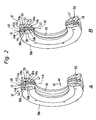
- FIG. 1 shows a valve 11 as part of a designated generally by reference numeral 12 valve assembly, which additionally has a preferably plate-like fluid distributor 13, on which the valve 11 is releasably secured by means of suitable fastening means 14.
- the valve 11 serves to control fluid flows and is designed as a multi-way valve.
- the medium to be controlled is in particular compressed air, although it may also be another gaseous or hydraulic medium.
- the valve 11 has a valve housing 15, in which at least one linearly extending, elongated housing recess 16 is provided. On the circumference, the housing recess 16 is bounded by a housing wall 17 of the valve housing 15.
- the housing wall 17 and in particular the entire valve housing 15 consist in the embodiment of plastic material.
- the preparation is advantageously carried out by injection molding, wherein a reworking of the housing recess 16 defining and radially inwardly oriented wall surface 18 of the housing wall 17 is not required or only to a small extent.
- a design made of metal would also be possible in principle.
- valve channels 19 a In the housing recess 16 open in the region of the wall surface 18 at a plurality of spaced in the longitudinal direction of the housing recess 16 locations valve channels 19 a. These pass through the housing wall 17 and form at its outer end connection openings 20. According to a preferred embodiment, three of these connection openings open to an outer mounting surface 21 of the valve housing 15, with which the valve 11 is attached to a mounting surface 22 of the fluid manifold 13. In the latter run a plurality of fluid distribution channels 23, which open to the mounting surface 22 and communicate there with the connection openings 20 in pairs.
- connection openings 20 open on a mounting surface 21 in particular opposite terminal surface 24 of the valve housing 15 and are intended to allow the connection not shown fluid lines leading to a consumer to be driven.
- the valve 11 of the embodiment is a 4/2-way valve. However, it is also conceivable to use 3/2 or 5/2-way valves.
- the valve channels 19 opening out to the mounting surface 21 are a central feed channel 19a, which is flanked axially by a venting channel 19b.
- the two leading to the terminal surface 24 valve channels 19 are working channels 19c and 19d.
- valves 11 On the fluid distributor 13, a plurality of valves 11 may be positioned, which are each associated with the correct allocation with the fluid distribution channels 23.
- valve spool 25 In the housing recess 16, an elongated piston-like valve spool 25 is arranged. He has several control sections 26 larger diameter, between each of which a control portion 27 of smaller diameter is placed.
- the valve spool 25 associated actuating means allow an axial displacement and positioning of the valve spool 25 in the housing recess 16 relative to the valve housing 15th
- the actuating means comprise a drive piston 28, which is in operative connection with the valve slide 25 at one end.
- the latter is displaceably guided under sealing in a end section of the housing recess 16 designated as actuating space 29.
- valve spool 25 opposite side of the drive piston 28 lying outer portion 30 of the actuating chamber 29 communicates in a manner not shown with a control channel 31 via which a fluidic control medium can be selectively supplied or removed.
- the corresponding control takes over an electrically activatable pilot valve 32 which is attached to the valve housing 15.
- Comparable actuation means may also be associated with the opposite end of the valve spool 25. Notwithstanding this, there is in the embodiment, however, only one return spring 33, which is effective between the valve housing 15 and the valve spool 25 and the valve spool 25 constantly applied in the direction of the drive piston.
- the valve slide 25 In the deactivated state of the pilot valve 32, the valve slide 25, due to the bias of the return spring 33, assumes the first switching position shown in the drawing.
- the pilot valve 32 By activating the pilot valve 32 is the drive piston 28 and thus the valve spool 25 is displaced with simultaneous compression of the return spring 33 to the right in a second switching position.
- the housing recess 16 is closed at both end sides. On at least one end side, the closure is effected by a closure cover 34 detachably fastened to the valve housing 15. In the removed state of the closure lid 34, the housing recess 16 is accessible from the corresponding front side.
- housing recess 16 In the housing recess 16 is an effective between the valve spool 25 and the housing wall 17 sealing means 35. It sits coaxially between the wall surface 18 and the valve spool 25, being interspersed coaxially by the latter.
- the sealing device has a sealing housing 36, which in turn is composed of at least one, preferably of a plurality of sealing units 37, wherein according to the embodiment, four or five sealing units 37 are provided.
- a sealing unit 37 is constructed in each case from a first, annular housing element 38a and a second, annular housing element 38b adjacent in the axial direction, an annular sealing element 39 being fixed between the first and second housing element 38a, 38b.
- the sealing element 39 consists of an outer section 40 with an outer sealing region 41 for sealing against the housing recess 16 and an inner section 42 with an inner sealing region 43 for sealing against the valve slide 25.
- the urging means is exemplified in the form of an annular, located on the housing outer portion 44b of the second housing member 38b, to be acted upon sealing member 39 facing bead 46.
- the bead 46 can penetrate into the outer section 40, so that the outer section deforms radially outward, thus achieving a sealing effect with respect to the housing recess 16.
- loading means on both housing elements 38a, 38b, for example to provide two opposing beads 46, between which the outer portion 40 of the sealing element 39 is clamped.
- An alternative is to provide a biasing means on the first housing member.
- the sealing element 39 further has at least one decoupling means 47, which causes the inner portion 42 of the sealing element 39 of the resulting from the application of the outer portion 40, radially inwardly directed Forces is decoupled.
- the decoupling means is exemplified by means of a transition section 47 which is arranged transversely to the outer and the inner portion 40, 41 of the sealing element 39 and is connected at one end to the outer portion 40 and the other end to the inner portion 41. It is achieved by the transition section 47 that the outer section radial plane 48 of the outer section 40, which contains the outer sealing area, is arranged axially offset from the inner section radial plane 49 of the inner section which contains the inner sealing area.
- the sealing element 39 has the overall shape of a stepped or stepped sealing ring, wherein outer portion, transition portion and inner portion 40, 42, 47 are integrally connected to each other and can be produced by a single sealing element manufacturing process.
- the sealing element 39 is made of a relatively soft elastomeric material, which is preferably softer than the bead 46 on the second housing element 38b, so that this can penetrate when clamping the housing elements 38a, 38b in the soft elastomeric material and deform the outer portion 40, so that the outer Sealing region 41 is pressed against the wall surface 18 of the housing wall 17.
- elastomeric material for example, a thermoplastic elastomer can be used.
- the first housing element 38a which can also be referred to as a carrier part, is intended to carry the sealing element 39.
- the holding means 50 are formed by the sealing element 39 itself, in particular, they are formed in the manufacture of the sealing element 39 with.
- the first housing element 38a is formed such that the sealing element 39 integrally formed thereon, preferably by means of an injection process, for example by means of an elastomer injection molding process can be molded on it.
- the first housing element 38a has, on its rear side opposite the sealing element 39, an annular, circumferential groove 52, on the groove base of which openings 53 are provided which open out at the front side of the first housing element 38a.
- the annular groove 52 and the openings 53 which are preferably formed as holes with a circular cross-section, serve to receive anchoring parts 54 of the holding means 50. It is possible, for example, the sealing element 39 from the back of the first housing member 38a forth first the annular groove 52 filling be sprayed so that plasticized sealing element material passes through the openings 53 to the inside and there is taken in a predetermining the shape of the sealing element 39 negative mold and solidifies there to its final shape.
- the individual sealing units 37 of the sealing device 35 are arranged at regular intervals along the housing recess 16 of the valve housing 15. This regular spacing is achieved by spacers or spacer elements 55, which are preferably fastened to the outside of the second housing element 38b facing away from the sealing element 39.
- the assembly of the sealing device 35 according to the embodiment shown from the side on which the pilot valve 32 is located, ie in a mounting direction 51 from left to right.
- first a first housing element 38a, together with the sealing element 39 fastened thereto, is inserted into the housing recess 16 until it reaches its predetermined location along the housing recess 16, which is formed by a graduation 56 on the closure cover 34 in the exemplary embodiment shown.
- the laterally opening into the housing recess 16 valve channels 19a to 19d are passed.
- the sealing elements relax when they are pressed over the mouths of the valve channels. As a result, the rubber elastic sealing material slightly deforms into the mouths. If the sealing device 35 is then pressed further in the mounting direction 51, the section of the sealing element deformed into the mouth remains hanging from the edge of the mouth, which can lead to damage of the sealing element.
- the sealing element 39 is not under tension during mounting, that is, it is not yet pressed against the wall surface 18 of the housing recess 6. The sealing effect is generated only with the clamping together of the two housing elements 38a, 38b.
- the sealing element 39 to be mounted also does not deform into the channel openings of the valve channels to be passed, which prevents the effect described above.
- the associated, second housing element 38b is inserted and clamped together with the first housing element, wherein the bead 46 located on the housing outer portion 44b of the second housing element 38b is pressed into the outer portion 40 of the sealing element 39, so that the outer portion 40 and thus the outer sealing region 41 radially outwardly deformed and a sealing effect against the wall surface 18 of the housing wall 17 is achieved.
- the transition section 47 formed between the outer section 40 and the inner section 42 and located transversely to these two sections prevents the inner section 42 from being deformed.
- the second housing element 38b On the outside of the second housing element 38b facing away from the sealing element 39, there are several, in particular three spacers 55 distributed over the circumference of the second housing element 38b, which determine the position of the next sealing unit 37 lying in front in the mounting direction 51.
- a first housing element together with sealing element 39 is inserted until it abuts the spacer.
- five sealing units 37 can be inserted gradually.
- the second housing element 38b no longer has a spacer 55, but expediently toothing means 57 with which this sealing unit 37 is fixed in the housing recess 16 and the entire sealing device 35 is latched against being pulled out against the mounting direction 51.
Landscapes
- Engineering & Computer Science (AREA)
- General Engineering & Computer Science (AREA)
- Mechanical Engineering (AREA)
- Multiple-Way Valves (AREA)
- Valve Housings (AREA)
- Magnetically Actuated Valves (AREA)
- Electrically Driven Valve-Operating Means (AREA)
- Temperature-Responsive Valves (AREA)
- Check Valves (AREA)
Claims (14)
- Soupape avec un boîtier de soupape (15) qui présente un évidement de boîtier (16) oblong, limité côté périphérie par une paroi de boîtier (17), prévu pour loger un tiroir de soupape (25), dans lequel au moins un canal de soupape (19) débouche latéralement et dans lequel est disposé un dispositif d'étanchéité (35) traversé par le tiroir de soupape (25), lequel possède un boîtier d'étanchéité (36) qui présente au moins un élément étanche (39) annulaire qui possède une section extérieure (40) avec une zone étanche (41) extérieure pour réaliser l'étanchéité par rapport à l'évidement de boîtier (16) et une section intérieure (42) avec une zone étanche (43) intérieure pour réaliser l'étanchéité par rapport au tiroir de soupape (25), le boîtier d'étanchéité (36) dans la zone de l'élément étanche (39) présentant deux éléments de boîtier (38a, 38b) annulaires, fixant l'élément étanche (39) entre eux, au moins l'un des éléments de boîtier (38a, 38b) disposant, sur le côté associé axialement à la section extérieure (40), d'au moins un moyen de sollicitation (46) qui sollicite localement lors du serrage des éléments de boîtier (38a, 38b) la section extérieure (40) de telle sorte que la section extérieure (40) puisse être pressée radialement vers l'extérieur contre la paroi de boîtier (17) pour obtenir un effet d'étanchéité étanche, la section extérieure (40) présentant un plan radial de section extérieure (48) contenant la zone d'étanchéité (41) extérieure et la section intérieure (42) présentant un plan radial de section intérieure (49) contenant la zone étanche (43) intérieure, et au moins un moyen de découplage étant prévu pour découpler la section intérieure (42) des forces dirigées radialement vers l'intérieur, résultant de la sollicitation de la section extérieure (40), sous la forme d'une section de transition (47) orientée alignée transversalement à la section extérieure et à la section intérieure (40, 42), reliée d'une part à la section extérieure (40) et d'autre part à la section intérieure (42), se trouvant entre la section extérieure (40) et la section intérieure (42), laquelle a pour effet que le plan radial de la section extérieure (48) soit disposé en déport axial par rapport au plan radial de la section intérieure (49), et les éléments de boîtier (38a, 38b) présentant des sections de transition de boîtier (58a, 58b) s'étendant de manière correspondante à la section de transition (47) de l'élément étanche (39), la section de transition (47) de l'élément étanche (39) étant disposée entre les sections de transition de boîtier (58a, 58b) à l'état monté du dispositif d'étanchéité (35), caractérisée en ce qu'un espace libre (59) est formé radialement entre la section de transition (47) de l'élément étanche (39) et la section de transition de boîtier (58a, 58b) jouxtant radialement à l'intérieur la section de transition à l'état monté du dispositif d'étanchéité (35).
- Soupape selon la revendication 1, caractérisée en ce que la section de transition (47) est alignée sensiblement perpendiculairement à la section extérieure et à la section intérieure (40, 42).
- Soupape selon la revendication 1 ou 2, caractérisée en ce que la section extérieure (40), la section de transition (47) et la section intérieure (42) sont reliées d'un seul tenant entre elles.
- Soupape selon l'une des revendications précédentes, caractérisée en ce que la section extérieure (40), la section de transition (47) et la section intérieure (42) sont fabriquées dans la même matière, en particulier en matière élastomère.
- Soupape selon la revendication 4, caractérisée en ce qu'un élastomère thermoplastique est prévu comme matière élastomère.
- Soupape selon l'une des revendications précédentes, caractérisée en ce qu'au moins un premier élément de boîtier (38a) est prévu, lequel est relié au moyen de moyens de retenue (50) à l'élément étanche (39) et au moins un second élément de boîtier (38b) est prévu, lequel dispose du moyen de sollicitation (46) servant à solliciter la section extérieure (40) de l'élément étanche (39).
- Soupape selon la revendication 6, caractérisée en ce qu'un bourrelet (46) annulaire est prévu comme moyen de sollicitation, lequel dépasse axialement du côté associé à la section extérieure (40) de l'élément étanche (39) du second élément de boîtier (38b).
- Soupape selon la revendication 7, caractérisée en ce que le bourrelet (46) est fabriqué en une matière plus dure que la matière de la section extérieure (40).
- Soupape selon l'une des revendications 6 à 8, caractérisée en ce que les moyens de retenue (50) forment un engagement positif entre le premier élément de boîtier (38a) et l'élément étanche (39) à retenir.
- Soupape selon l'une des revendications 6 à 9, caractérisée en ce que les moyens de retenue (50) sont formés par l'élément étanche (39) lui-même, de préférence sont surmoulés sur celui-ci.
- Soupape selon l'une des revendications 6 à 10, caractérisée en ce que le premier élément de boîtier (38a) présente sur son côté arrière, éloigné de l'élément étanche, une rainure (52) annulaire destinée à loger une partie d'ancrage (54) réalisée de manière correspondante du moyen de retenue (50) associé, la rainure (52) étant reliée par le biais d'ouvertures (53) réparties en particulier à distances régulières sur la périphérie de la rainure (52), et s'étendant dans le sens axial, au côté avant de l'élément de boîtier (38a), lesquelles sont traversées par les moyens de retenue (50).
- Soupape selon l'une des revendications précédentes, caractérisée en ce que les premiers et/ou les seconds éléments de boîtier (38a, 38b) sont couplés sur leurs côtés arrière éloignés de l'élément étanche (39) par le biais d'éléments d'écartement (55) avec d'autres premiers ou seconds éléments de boîtier (38a, 38b) contigus, le premier élément de boîtier (38a) étant couplé de préférence avec un autre second élément de boîtier contigu et le second élément de boîtier (38b) avec un autre premier élément de boîtier (38a) contigu.
- Soupape selon la revendication 12, caractérisée en ce que les élément d'écartement (50) sont fixés sur le second élément de boîtier (38b), en particulier sont surmoulés dessus.
- Soupape selon l'une des revendications précédentes, caractérisée en ce que les premiers et les seconds éléments de boîtier (38a, 38b) sont fabriqués dans la même matière, en particulier en matière polymère.
Applications Claiming Priority (2)
| Application Number | Priority Date | Filing Date | Title |
|---|---|---|---|
| DE102004007091 | 2004-02-13 | ||
| DE102004007091A DE102004007091B3 (de) | 2004-02-13 | 2004-02-13 | Ventil |
Publications (2)
| Publication Number | Publication Date |
|---|---|
| EP1564458A1 EP1564458A1 (fr) | 2005-08-17 |
| EP1564458B1 true EP1564458B1 (fr) | 2008-09-24 |
Family
ID=34684036
Family Applications (1)
| Application Number | Title | Priority Date | Filing Date |
|---|---|---|---|
| EP05001872A Expired - Lifetime EP1564458B1 (fr) | 2004-02-13 | 2005-01-29 | Soupape |
Country Status (4)
| Country | Link |
|---|---|
| EP (1) | EP1564458B1 (fr) |
| AT (1) | ATE409296T1 (fr) |
| DE (2) | DE102004007091B3 (fr) |
| ES (1) | ES2311886T3 (fr) |
Families Citing this family (1)
| Publication number | Priority date | Publication date | Assignee | Title |
|---|---|---|---|---|
| DE102008032716B4 (de) * | 2008-07-11 | 2011-03-31 | Knorr-Bremse Systeme für Nutzfahrzeuge GmbH | Ventil mit hoher mittlerer Betriebsdauer |
Family Cites Families (6)
| Publication number | Priority date | Publication date | Assignee | Title |
|---|---|---|---|---|
| DE1287878B (de) * | 1969-01-23 | Hoerbiger Ventilwerke Ag, Wien | Einrichtung zum Abdichten von axial verschiebbaren Steuerkolben, Stangen u.dgl | |
| US2892644A (en) * | 1954-06-18 | 1959-06-30 | Int Basic Economy Corp | Packing means for plunger valves |
| US3451430A (en) * | 1966-11-16 | 1969-06-24 | Lloyd D Cowdin | Fluid control valve |
| DE3043871A1 (de) * | 1980-11-21 | 1982-07-08 | Wabco Steuerungstechnik GmbH & Co, 3000 Hannover | Mehrwegeventil |
| DE3240552C2 (de) * | 1982-11-03 | 1986-08-28 | Prädifa Präzisions-Dichtungs-Fabrik GmbH, 7120 Bietigheim-Bissingen | Schieberventildichtung |
| DE4101049C2 (de) * | 1991-01-16 | 1997-08-21 | Miele & Cie | Teleskopierbares Saugrohr eines Staubsaugers |
-
2004
- 2004-02-13 DE DE102004007091A patent/DE102004007091B3/de not_active Expired - Fee Related
-
2005
- 2005-01-29 EP EP05001872A patent/EP1564458B1/fr not_active Expired - Lifetime
- 2005-01-29 DE DE502005005438T patent/DE502005005438D1/de not_active Expired - Lifetime
- 2005-01-29 ES ES05001872T patent/ES2311886T3/es not_active Expired - Lifetime
- 2005-01-29 AT AT05001872T patent/ATE409296T1/de not_active IP Right Cessation
Also Published As
| Publication number | Publication date |
|---|---|
| DE102004007091B3 (de) | 2005-07-28 |
| EP1564458A1 (fr) | 2005-08-17 |
| DE502005005438D1 (de) | 2008-11-06 |
| ATE409296T1 (de) | 2008-10-15 |
| ES2311886T3 (es) | 2009-02-16 |
Similar Documents
| Publication | Publication Date | Title |
|---|---|---|
| DE69708991T2 (de) | Wechselventil mit Mitteln zur Vermeidung von Gegenstrom | |
| DE3831554C2 (de) | Drosselrückschlagventil | |
| EP0279930B1 (fr) | Dispositif de respiration pour un cylindre de frein à ressort | |
| DE102013208459A1 (de) | Geberzylinder | |
| DE2651133C3 (de) | Dosierventil für Schmiersysteme | |
| EP3067598A1 (fr) | Vanne multi-voies | |
| EP2924327B1 (fr) | Vanne multi-voies | |
| DE102005003982A1 (de) | Pneumatisches Wegeventil mit einem Ventilschieber | |
| DE102019211004A1 (de) | Ventil | |
| EP1564458B1 (fr) | Soupape | |
| EP4056880A1 (fr) | Joint d'étanchéité de piston rotatif | |
| DE102019200784B4 (de) | Rückschlagventil | |
| DE2854572A1 (de) | Durch fluessigkeitsdruck betaetigbares pilotventil | |
| DE102018114238B4 (de) | Gesteuertes Bremsmagnetventil | |
| DE2449443A1 (de) | Rueckschlagventil | |
| DE102015003062A1 (de) | Mehrwegeventil | |
| DE202005016282U1 (de) | Ventilglied und damit ausgestattetes Ventil | |
| EP1572512A1 (fr) | Piston pour un systeme de freinage hydraulique et matre-cylindre pourvu dudit piston | |
| DE102006018088A1 (de) | Führungsmechanismus für Zylindervorrichtung | |
| DE102005048593A1 (de) | Kunststoffleitung, insbesondere hydraulische Kupplungsdruck-Übertragungsleitung für ein Kraftfahrzeug, und Verfahren zum Herstellen einer Kunststoffleitung | |
| DE102009056496A1 (de) | Drosselventil | |
| DE4119402A1 (de) | Schieberventil | |
| WO2022171463A1 (fr) | Ensemble pour une unité piston-cylindre remplie de fluide et unité piston-cylindre remplie de fluide dotée d'un ensemble de ce type | |
| EP1517072B1 (fr) | Vanne | |
| DE102019133667A1 (de) | Vorrichtung zur Regelung von Drücken eines Strömungsmittels mit einem Ven-til |
Legal Events
| Date | Code | Title | Description |
|---|---|---|---|
| PUAI | Public reference made under article 153(3) epc to a published international application that has entered the european phase |
Free format text: ORIGINAL CODE: 0009012 |
|
| AK | Designated contracting states |
Kind code of ref document: A1 Designated state(s): AT BE BG CH CY CZ DE DK EE ES FI FR GB GR HU IE IS IT LI LT LU MC NL PL PT RO SE SI SK TR |
|
| AX | Request for extension of the european patent |
Extension state: AL BA HR LV MK YU |
|
| 17P | Request for examination filed |
Effective date: 20050707 |
|
| AKX | Designation fees paid |
Designated state(s): AT BE BG CH CY CZ DE DK EE ES FI FR GB GR HU IE IS IT LI LT LU MC NL PL PT RO SE SI SK TR |
|
| GRAP | Despatch of communication of intention to grant a patent |
Free format text: ORIGINAL CODE: EPIDOSNIGR1 |
|
| RAP1 | Party data changed (applicant data changed or rights of an application transferred) |
Owner name: FESTO AG & CO. KG |
|
| GRAS | Grant fee paid |
Free format text: ORIGINAL CODE: EPIDOSNIGR3 |
|
| GRAA | (expected) grant |
Free format text: ORIGINAL CODE: 0009210 |
|
| AK | Designated contracting states |
Kind code of ref document: B1 Designated state(s): AT BE BG CH CY CZ DE DK EE ES FI FR GB GR HU IE IS IT LI LT LU MC NL PL PT RO SE SI SK TR |
|
| REG | Reference to a national code |
Ref country code: GB Ref legal event code: FG4D Free format text: NOT ENGLISH |
|
| REG | Reference to a national code |
Ref country code: CH Ref legal event code: EP |
|
| REG | Reference to a national code |
Ref country code: IE Ref legal event code: FG4D Free format text: LANGUAGE OF EP DOCUMENT: GERMAN |
|
| REF | Corresponds to: |
Ref document number: 502005005438 Country of ref document: DE Date of ref document: 20081106 Kind code of ref document: P |
|
| PG25 | Lapsed in a contracting state [announced via postgrant information from national office to epo] |
Ref country code: LT Free format text: LAPSE BECAUSE OF FAILURE TO SUBMIT A TRANSLATION OF THE DESCRIPTION OR TO PAY THE FEE WITHIN THE PRESCRIBED TIME-LIMIT Effective date: 20080924 |
|
| REG | Reference to a national code |
Ref country code: ES Ref legal event code: FG2A Ref document number: 2311886 Country of ref document: ES Kind code of ref document: T3 |
|
| PG25 | Lapsed in a contracting state [announced via postgrant information from national office to epo] |
Ref country code: SI Free format text: LAPSE BECAUSE OF FAILURE TO SUBMIT A TRANSLATION OF THE DESCRIPTION OR TO PAY THE FEE WITHIN THE PRESCRIBED TIME-LIMIT Effective date: 20080924 Ref country code: FI Free format text: LAPSE BECAUSE OF FAILURE TO SUBMIT A TRANSLATION OF THE DESCRIPTION OR TO PAY THE FEE WITHIN THE PRESCRIBED TIME-LIMIT Effective date: 20080924 |
|
| NLV1 | Nl: lapsed or annulled due to failure to fulfill the requirements of art. 29p and 29m of the patents act | ||
| REG | Reference to a national code |
Ref country code: IE Ref legal event code: FD4D |
|
| PG25 | Lapsed in a contracting state [announced via postgrant information from national office to epo] |
Ref country code: BG Free format text: LAPSE BECAUSE OF FAILURE TO SUBMIT A TRANSLATION OF THE DESCRIPTION OR TO PAY THE FEE WITHIN THE PRESCRIBED TIME-LIMIT Effective date: 20081224 |
|
| PG25 | Lapsed in a contracting state [announced via postgrant information from national office to epo] |
Ref country code: SK Free format text: LAPSE BECAUSE OF FAILURE TO SUBMIT A TRANSLATION OF THE DESCRIPTION OR TO PAY THE FEE WITHIN THE PRESCRIBED TIME-LIMIT Effective date: 20080924 Ref country code: RO Free format text: LAPSE BECAUSE OF FAILURE TO SUBMIT A TRANSLATION OF THE DESCRIPTION OR TO PAY THE FEE WITHIN THE PRESCRIBED TIME-LIMIT Effective date: 20080924 Ref country code: PT Free format text: LAPSE BECAUSE OF FAILURE TO SUBMIT A TRANSLATION OF THE DESCRIPTION OR TO PAY THE FEE WITHIN THE PRESCRIBED TIME-LIMIT Effective date: 20090224 Ref country code: NL Free format text: LAPSE BECAUSE OF FAILURE TO SUBMIT A TRANSLATION OF THE DESCRIPTION OR TO PAY THE FEE WITHIN THE PRESCRIBED TIME-LIMIT Effective date: 20080924 Ref country code: IS Free format text: LAPSE BECAUSE OF FAILURE TO SUBMIT A TRANSLATION OF THE DESCRIPTION OR TO PAY THE FEE WITHIN THE PRESCRIBED TIME-LIMIT Effective date: 20090124 Ref country code: CZ Free format text: LAPSE BECAUSE OF FAILURE TO SUBMIT A TRANSLATION OF THE DESCRIPTION OR TO PAY THE FEE WITHIN THE PRESCRIBED TIME-LIMIT Effective date: 20080924 |
|
| PG25 | Lapsed in a contracting state [announced via postgrant information from national office to epo] |
Ref country code: IE Free format text: LAPSE BECAUSE OF FAILURE TO SUBMIT A TRANSLATION OF THE DESCRIPTION OR TO PAY THE FEE WITHIN THE PRESCRIBED TIME-LIMIT Effective date: 20080924 Ref country code: EE Free format text: LAPSE BECAUSE OF FAILURE TO SUBMIT A TRANSLATION OF THE DESCRIPTION OR TO PAY THE FEE WITHIN THE PRESCRIBED TIME-LIMIT Effective date: 20080924 Ref country code: DK Free format text: LAPSE BECAUSE OF FAILURE TO SUBMIT A TRANSLATION OF THE DESCRIPTION OR TO PAY THE FEE WITHIN THE PRESCRIBED TIME-LIMIT Effective date: 20080924 |
|
| PLBE | No opposition filed within time limit |
Free format text: ORIGINAL CODE: 0009261 |
|
| STAA | Information on the status of an ep patent application or granted ep patent |
Free format text: STATUS: NO OPPOSITION FILED WITHIN TIME LIMIT |
|
| PG25 | Lapsed in a contracting state [announced via postgrant information from national office to epo] |
Ref country code: MC Free format text: LAPSE BECAUSE OF NON-PAYMENT OF DUE FEES Effective date: 20090131 |
|
| REG | Reference to a national code |
Ref country code: CH Ref legal event code: PL |
|
| 26N | No opposition filed |
Effective date: 20090625 |
|
| PG25 | Lapsed in a contracting state [announced via postgrant information from national office to epo] |
Ref country code: LI Free format text: LAPSE BECAUSE OF NON-PAYMENT OF DUE FEES Effective date: 20090131 Ref country code: CH Free format text: LAPSE BECAUSE OF NON-PAYMENT OF DUE FEES Effective date: 20090131 |
|
| PG25 | Lapsed in a contracting state [announced via postgrant information from national office to epo] |
Ref country code: SE Free format text: LAPSE BECAUSE OF FAILURE TO SUBMIT A TRANSLATION OF THE DESCRIPTION OR TO PAY THE FEE WITHIN THE PRESCRIBED TIME-LIMIT Effective date: 20081224 |
|
| PG25 | Lapsed in a contracting state [announced via postgrant information from national office to epo] |
Ref country code: BE Free format text: LAPSE BECAUSE OF NON-PAYMENT OF DUE FEES Effective date: 20090131 |
|
| PG25 | Lapsed in a contracting state [announced via postgrant information from national office to epo] |
Ref country code: PL Free format text: LAPSE BECAUSE OF FAILURE TO SUBMIT A TRANSLATION OF THE DESCRIPTION OR TO PAY THE FEE WITHIN THE PRESCRIBED TIME-LIMIT Effective date: 20080924 |
|
| PG25 | Lapsed in a contracting state [announced via postgrant information from national office to epo] |
Ref country code: AT Free format text: LAPSE BECAUSE OF NON-PAYMENT OF DUE FEES Effective date: 20090129 |
|
| PG25 | Lapsed in a contracting state [announced via postgrant information from national office to epo] |
Ref country code: GR Free format text: LAPSE BECAUSE OF FAILURE TO SUBMIT A TRANSLATION OF THE DESCRIPTION OR TO PAY THE FEE WITHIN THE PRESCRIBED TIME-LIMIT Effective date: 20081225 |
|
| PG25 | Lapsed in a contracting state [announced via postgrant information from national office to epo] |
Ref country code: LU Free format text: LAPSE BECAUSE OF NON-PAYMENT OF DUE FEES Effective date: 20090129 |
|
| PG25 | Lapsed in a contracting state [announced via postgrant information from national office to epo] |
Ref country code: HU Free format text: LAPSE BECAUSE OF FAILURE TO SUBMIT A TRANSLATION OF THE DESCRIPTION OR TO PAY THE FEE WITHIN THE PRESCRIBED TIME-LIMIT Effective date: 20090325 |
|
| PG25 | Lapsed in a contracting state [announced via postgrant information from national office to epo] |
Ref country code: TR Free format text: LAPSE BECAUSE OF FAILURE TO SUBMIT A TRANSLATION OF THE DESCRIPTION OR TO PAY THE FEE WITHIN THE PRESCRIBED TIME-LIMIT Effective date: 20080924 |
|
| PG25 | Lapsed in a contracting state [announced via postgrant information from national office to epo] |
Ref country code: CY Free format text: LAPSE BECAUSE OF FAILURE TO SUBMIT A TRANSLATION OF THE DESCRIPTION OR TO PAY THE FEE WITHIN THE PRESCRIBED TIME-LIMIT Effective date: 20080924 |
|
| PGFP | Annual fee paid to national office [announced via postgrant information from national office to epo] |
Ref country code: ES Payment date: 20150122 Year of fee payment: 11 |
|
| REG | Reference to a national code |
Ref country code: FR Ref legal event code: PLFP Year of fee payment: 12 |
|
| REG | Reference to a national code |
Ref country code: FR Ref legal event code: PLFP Year of fee payment: 13 |
|
| PGFP | Annual fee paid to national office [announced via postgrant information from national office to epo] |
Ref country code: GB Payment date: 20161222 Year of fee payment: 13 |
|
| REG | Reference to a national code |
Ref country code: ES Ref legal event code: FD2A Effective date: 20170227 |
|
| PG25 | Lapsed in a contracting state [announced via postgrant information from national office to epo] |
Ref country code: ES Free format text: LAPSE BECAUSE OF NON-PAYMENT OF DUE FEES Effective date: 20160130 |
|
| REG | Reference to a national code |
Ref country code: FR Ref legal event code: PLFP Year of fee payment: 14 |
|
| GBPC | Gb: european patent ceased through non-payment of renewal fee |
Effective date: 20180129 |
|
| PG25 | Lapsed in a contracting state [announced via postgrant information from national office to epo] |
Ref country code: GB Free format text: LAPSE BECAUSE OF NON-PAYMENT OF DUE FEES Effective date: 20180129 |
|
| PGFP | Annual fee paid to national office [announced via postgrant information from national office to epo] |
Ref country code: IT Payment date: 20190121 Year of fee payment: 15 Ref country code: FR Payment date: 20190122 Year of fee payment: 15 |
|
| REG | Reference to a national code |
Ref country code: DE Ref legal event code: R082 Ref document number: 502005005438 Country of ref document: DE Representative=s name: PATENTANWAELTE MAGENBAUER & KOLLEGEN PARTNERSC, DE Ref country code: DE Ref legal event code: R081 Ref document number: 502005005438 Country of ref document: DE Owner name: FESTO AG & CO. KG, DE Free format text: FORMER OWNER: FESTO AG & CO. KG, 73734 ESSLINGEN, DE Ref country code: DE Ref legal event code: R081 Ref document number: 502005005438 Country of ref document: DE Owner name: FESTO SE & CO. KG, DE Free format text: FORMER OWNER: FESTO AG & CO. KG, 73734 ESSLINGEN, DE |
|
| PGFP | Annual fee paid to national office [announced via postgrant information from national office to epo] |
Ref country code: DE Payment date: 20191214 Year of fee payment: 16 |
|
| PG25 | Lapsed in a contracting state [announced via postgrant information from national office to epo] |
Ref country code: FR Free format text: LAPSE BECAUSE OF NON-PAYMENT OF DUE FEES Effective date: 20200131 |
|
| PG25 | Lapsed in a contracting state [announced via postgrant information from national office to epo] |
Ref country code: IT Free format text: LAPSE BECAUSE OF NON-PAYMENT OF DUE FEES Effective date: 20200129 |
|
| REG | Reference to a national code |
Ref country code: DE Ref legal event code: R119 Ref document number: 502005005438 Country of ref document: DE |
|
| PG25 | Lapsed in a contracting state [announced via postgrant information from national office to epo] |
Ref country code: DE Free format text: LAPSE BECAUSE OF NON-PAYMENT OF DUE FEES Effective date: 20210803 |