EP1564458A1 - Soupape - Google Patents
Soupape Download PDFInfo
- Publication number
- EP1564458A1 EP1564458A1 EP05001872A EP05001872A EP1564458A1 EP 1564458 A1 EP1564458 A1 EP 1564458A1 EP 05001872 A EP05001872 A EP 05001872A EP 05001872 A EP05001872 A EP 05001872A EP 1564458 A1 EP1564458 A1 EP 1564458A1
- Authority
- EP
- European Patent Office
- Prior art keywords
- housing
- sealing
- valve
- valve according
- sealing element
- Prior art date
- Legal status (The legal status is an assumption and is not a legal conclusion. Google has not performed a legal analysis and makes no representation as to the accuracy of the status listed.)
- Granted
Links
Images

Classifications
-
- F—MECHANICAL ENGINEERING; LIGHTING; HEATING; WEAPONS; BLASTING
- F16—ENGINEERING ELEMENTS AND UNITS; GENERAL MEASURES FOR PRODUCING AND MAINTAINING EFFECTIVE FUNCTIONING OF MACHINES OR INSTALLATIONS; THERMAL INSULATION IN GENERAL
- F16K—VALVES; TAPS; COCKS; ACTUATING-FLOATS; DEVICES FOR VENTING OR AERATING
- F16K11/00—Multiple-way valves, e.g. mixing valves; Pipe fittings incorporating such valves
- F16K11/02—Multiple-way valves, e.g. mixing valves; Pipe fittings incorporating such valves with all movable sealing faces moving as one unit
- F16K11/06—Multiple-way valves, e.g. mixing valves; Pipe fittings incorporating such valves with all movable sealing faces moving as one unit comprising only sliding valves, i.e. sliding closure elements
- F16K11/065—Multiple-way valves, e.g. mixing valves; Pipe fittings incorporating such valves with all movable sealing faces moving as one unit comprising only sliding valves, i.e. sliding closure elements with linearly sliding closure members
- F16K11/07—Multiple-way valves, e.g. mixing valves; Pipe fittings incorporating such valves with all movable sealing faces moving as one unit comprising only sliding valves, i.e. sliding closure elements with linearly sliding closure members with cylindrical slides
- F16K11/0712—Multiple-way valves, e.g. mixing valves; Pipe fittings incorporating such valves with all movable sealing faces moving as one unit comprising only sliding valves, i.e. sliding closure elements with linearly sliding closure members with cylindrical slides comprising particular spool-valve sealing means
-
- F—MECHANICAL ENGINEERING; LIGHTING; HEATING; WEAPONS; BLASTING
- F16—ENGINEERING ELEMENTS AND UNITS; GENERAL MEASURES FOR PRODUCING AND MAINTAINING EFFECTIVE FUNCTIONING OF MACHINES OR INSTALLATIONS; THERMAL INSULATION IN GENERAL
- F16K—VALVES; TAPS; COCKS; ACTUATING-FLOATS; DEVICES FOR VENTING OR AERATING
- F16K31/00—Actuating devices; Operating means; Releasing devices
- F16K31/12—Actuating devices; Operating means; Releasing devices actuated by fluid
- F16K31/122—Actuating devices; Operating means; Releasing devices actuated by fluid the fluid acting on a piston
- F16K31/1221—Actuating devices; Operating means; Releasing devices actuated by fluid the fluid acting on a piston one side of the piston being spring-loaded
Definitions
- the invention relates to a valve with a valve housing, the one provided for receiving a valve spool, circumferentially from a housing wall limited elongated housing recess has, in the laterally at least one valve channel opens and in the one penetrated by the valve spool Seal device is arranged, which is a seal housing has, at least one annular sealing element that holds an outer section with outer sealing area to Seal against the housing recess and an inner portion with inner sealing area for sealing against the Valve slide has.
- Such a valve is for example from DE 41 01 049 C2 is known in which a sealing device for a multi-way valve is described, in which a holding sleeve provided is that can be inserted into a receptacle and comprises a plurality of annular sealing elements, each both an inner sealing edge for sealing against the valve spool and an outer sealing edge for sealing against having the housing recess.
- a multi-way valve is known, with a Housing, which has a housing recess in which a Valve slide is mounted axially displaceable.
- the as a guide hole designated housing recess is stepped, wherein seen from the mounting opening in diameter smaller expectant sections are provided.
- the respective sections the guide bore are each with a spacer-sealing ring combination, consisting of a spacer and an annular sealing element can be fitted.
- the sealing elements serve both to seal against the wall of the respective guide bore section as well as for sealing opposite the valve spool.
- a problem of the previously described prior art is the assembly of the sealing device or the seals in the housing recess of the valve housing.
- the housing recess open laterally a plurality of valve channels, which otherwise closed and smooth wall of the housing recess interrupt, with the mouth edges of the valve port mouths may be formed relatively sharp.
- the gasket must be pressed against the housing wall in a press fit.
- the object of the invention is a valve of the aforementioned To create a way in which the sealing device is simple, can be mounted quickly and reliably.
- the valve according to the invention is characterized in that the seal housing in the region of the sealing element two the Sealing element between itself fixing, annular housing elements wherein at least one of the housing elements at the outer portion axially associated side over at least has a loading means that when clamping together the housing elements locally the outer portion such causes the outer section to achieve a Sealing effect radially outwardly pressed against the housing wall and wherein at least one decoupling means is provided is that causes the inner portion of the from the impingement of the outer portion resulting, radially decoupled inwardly directed forces.
- the sealing effect unfolds preferably only when the relevant Sealing element its previously determined axial position along the Housing recess has reached and the two, the relevant Clamping element flanking housing elements clamped together be, wherein the outer portion of the sealing element radially is pressed against the outside of the housing wall.
- the one or more decoupling effect in addition to "Power decoupling" that a manufacturing tolerance on the outside Sealing area of the outer section does not affect the inner Sealing area has. So it can be prevented that for sealing against the housing recess, which too called static seal with static sealing edge can be, required radial forces and / or tolerances not transferred to the inner portion of the sealing element so that the seal against the valve spool - also called dynamic sealing with dynamic sealing edge - this is essentially unaffected. It will So in particular the problem avoided that the inner Sealing area when exposed to the outer section of the Valve spool presses, resulting in increased friction between Valve spool and sealing element would result, with the increased Friction to a malfunction when switching the valve could lead.
- the outer section has of the sealing element containing the outer sealing area Outer section radial plane and the inner section an inner section radial plane containing the inner sealing region.
- a decoupling means is an intermediate the outer portion and inner portion befindaji, on the one hand with the outer portion and on the other hand with the inner portion connected, transversely to the outer and inner section provided aligned transition section, which causes the outer section radial plane is offset axially is arranged to the inner-section radial plane.
- the sealing element can therefore have an angled or stepped shape.
- the transition section is essential perpendicular or at approximately 90 ° to the outer and inner sections aligned. Exterior and interior section can so in the assembled state of the sealing device in radial Direction be aligned while the transition section in essentially runs in the axial direction.
- the housing elements can be adapted to the shape of the sealing element For example, they may have housing transition sections own, in the mounted state of the sealing device corresponding to the transition section of the sealing element are formed.
- the housing elements can so also be formed angled or graded.
- outer section, transition section and inner portion integrally connected. You can thus produced by a single manufacturing process become.
- outer portion, transition portion and inner section made of the same material, in particular of elastomeric material. It is possible Such a sealing element by an elastomer injection process manufacture.
- thermoplastic elastomer used. However, other Elastormerart can be used.
- the sealing device has at least a first housing element, by means of Holding means in particular form-fitting with the sealing element is connected and has at least a second housing element on, the on the at least one Loading the outer portion of the sealing element has.
- the biasing means is integral with the connected to the second housing element.
- the loading means as a separate component form and attach to the respective housing element.
- a pressurizing means is a ring-shaped Bead provided by the outer portion of the Sealing element associated side of the second housing element protrudes axially. When clamping the housing elements the bead can "dig in” in the outer section, so that this pressed radially outward on the housing wall becomes.
- the bead is preferably one compared to Exterior section made of harder material, allowing the impingement the outer portion a deformation of the outer portion and does not give a deformation of the bead.
- the holding means via which the first housing element and the Sealing element in particular positively connected to each other can be, are preferably integrally formed on the sealing element. So you can form part of the sealing element. Alternatively, it would be possible the retaining means on the housing element provided.
- the sealing element is merely by a form-fitting forming holding means on the relevant Housing element held so that the outer portion can deform in radial directions, as opposed to a full-surface cohesive connection between the sealing element and housing element, in which the sealing element firmly and immobile with the housing member in radial directions connected is.
- the first housing member may at its the annular A sealing element facing away from the rear side an annular groove for Receiving a correspondingly formed anchoring section having the associated holding means, wherein the groove over in the axial direction, in particular in periodically distributed over the circumference of the groove, from The holding means through openings, in particular cylindrical Holes, with the front of the first housing element connected is.
- the seal housing may consist of several first and several second housing elements, wherein the first and / or second housing elements facing away from the sealing element Rear sides over spacers or spacers with adjacent coupled to first or second housing elements are. It is possible that the first housing element via distance switch with a neighboring second and the second Housing element accordingly with an adjacent first Housing element is coupled. Preferably, located the spacers only on the backs of the second, the loading means having housing elements, In particular, the spacers are integral with the second Housing element connected.
- the first and second housing elements may be made of the same Material be made, for example, of polymer material. However, other materials can be used, for example Metals and / or metal alloys.
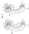
- FIG. 1 shows a valve 11 as part of a total designated by reference numeral 12 valve assembly, the additionally on a preferably plate-like trained Fluid distributor 13 has, on which the valve 11 solvable, by means of suitable fastening means 14, is attached.
- the valve 11 is used to control fluid flows and is designed as a multi-way valve.
- the medium to be controlled it is in particular compressed air, although it is also to another gaseous or hydraulic Medium can act.
- the valve 11 has a valve housing 15 in which at least a linearly extending, elongated housing recess 16 is provided. On the circumference is the housing recess 16 bounded by a housing wall 17 of the valve housing 15.
- the housing wall 17 and in particular the entire valve housing 15 consist in the embodiment of plastic material.
- the preparation is advantageously carried out by injection molding, wherein a reworking of the housing recess 16 defining and radially inwardly oriented wall surface 18th the housing wall 17 is not required or only to a small extent is.
- a design made of metal would in principle also possible.
- valve channels 19 a In the housing recess 16 open in the region of the wall surface 18 at a plurality in the longitudinal direction of the housing recess 16th spaced locations valve channels 19 a. Enforce this the housing wall 17 and form at its outer end connection openings 20. According to preferred embodiment three of these connection openings lead to an external one Mounting surface 21 of the valve housing 15, with the valve 11th attached to a mounting surface 22 of the fluid manifold 13 is. In the latter run several fluid distribution channels 23, which open to the mounting surface 22 and there with the connection openings 20 communicate in pairs.
- connection openings open 20 on one of the mounting surface 21 in particular opposite terminal surface 24 of the valve housing 15th and are intended to connect not shown To allow fluid lines to be controlled to a Lead consumers.
- the valve 11 of the embodiment is a 4/2-way valve. However, it is also conceivable 3/2 or 5/2-way valves use. When shown 4/2-way valve acts it is at the opening to the mounting surface 21 valve channels 19 about a central feed channel 19 a, the axial flanked by a vent channel 19b. The two to Pad 24 leading valve channels 19 are working channels 19c and 19d.
- valves 11 On the fluid manifold 13 a plurality of valves 11 can be positioned be, each matching correctly with the fluid distribution channels 23 are connected.
- valve slide 25 In the housing recess 16 is an elongated piston-like Valve slide 25 is arranged. He has several control sections 26 larger diameter, between each one a control portion 27 of smaller diameter is placed. Enable the valve spool 25 associated actuating means an axial displacement and positioning of the valve slide 25 in the housing recess 16 relative to the valve housing 15th
- the actuating means include in the embodiment a with the valve spool 25 at one end in operative connection standing drive piston 28. This is in a as operating space 29 designated end portion of the housing recess 16 slidably guided under sealing.
- valve spool 25 opposite side of the Drive piston 28 lying outer portion 30 of the operating space 29 communicates in a manner not shown with a control channel 31 through which a fluidic control medium optionally supplied or discharged.
- the appropriate control takes over an electrically activated Pilot valve 32 which is attached to the valve housing 15 is.
- Comparable actuators may also be the opposite Be assigned to the end of the valve spool 25. deviant However, this is there in the embodiment, however only one return spring 33, between the valve housing 15 and the valve spool 25 is effective and the valve spool 25 constantly applied in the direction of the drive piston.
- the housing recess 16 is closed at both end sides. On at least one front side of the closure takes place by a cover plate detachably fastened to the valve housing 15 34. In the removed state of the closure lid 34 is the housing recess 16 from the corresponding end face accessible.
- the sealing device has a seal housing 36 which in turn at least one, preferably several Seal units 37 is constructed, wherein according to the embodiment four or five sealing units 37 available are.
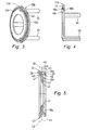
- a sealing unit 37 each consist of a first, annular housing element 38a and a second adjacent in the axial direction, annular housing member 38 b constructed, wherein between the first and second housing members 38a, 38b an annular Sealing element 39 is fixed.
- the sealing element 39 consists of an outer portion 40 with outer sealing region 41 for sealing against the housing recess 16 and an inner portion 42 with inner sealing area 43 for sealing against the valve spool 25th
- the Beauftschungsstoff is exemplified in the form of an am Housing outer portion 44b of the second housing member 38b located, annular, to be acted upon sealing element 39 facing bead 46 shown.
- the bead 46 can during clamping of the housing elements in the outer section 40 penetrate, so that the outer section after deformed radially outside, creating a sealing effect against the Housing recess 16 is achieved.
- Beaufschlagungsstoff on both housing elements Provide 38a, 38b, for example, two opposing To provide beads 46, between which the outer portion 40 of the sealing element 39 is clamped.
- An alternative is to provide a loading means on the first housing element.
- the sealing element 39 further has at least one decoupling means 47, which causes the inner portion 42 of the Sealing element 39 from the out of the loading of the outer portion 40 resulting, radially inward Forces is decoupled.
- the decoupling means is exemplary illustrated by a transition section 47, the transverse to the outer and inner portions 40, 41 of the sealing element 39 is arranged and one end with the outer section 40 and the other end is connected to the inner portion 41.
- the sealing element 39 has the overall shape of a remote or stepped seal ring, wherein outer section, Transition portion and inner portion 40, 42, 47 in one piece connected together and by a single sealing element manufacturing process can be produced.
- the sealing element 39 is made of a relatively soft elastomeric material, which is preferably softer than the bead 46 on the second Housing element 38b, so that this when clamping together the housing elements 38a, 38b in the soft elastomeric material penetrate and deform the outer portion 40, so that the outer sealing region 41 against the wall surface 18 of the housing wall 17 is pressed.
- elastomeric material for example a thermoplastic elastomer can be used.
- the first housing element 38a which also referred to as a carrier part can be determined to carry the sealing element 39.
- the holding means 50 are formed by the sealing element 39 itself, In particular, they are used in the manufacture of the sealing element 39 with molded.
- the first housing element 38a formed such that the sealing element 39th molded thereto, preferably by means of an injection process, for example by means of an elastomer injection molding process can be sprayed on it.
- the first housing element has 38 a at its the sealing element 39 opposite Rear side an annular circumferential groove 52, at the Nutgrund openings 53 are provided, which at the front of the first housing element 38a.
- the annular Groove 52 and the openings 53 preferably as bores are formed with a circular cross-section serve for receiving anchoring parts 54 of the holding means 50.
- the sealing element 39 of the Rear side of the first housing element 38a ago first the annular groove 52 to inject, so that plasticized Seal element material via the openings 53 to the inside passes and there in a the shape of the sealing element 39 given negative form and there solidified to its final form.
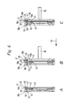
- the individual sealing units 37 of the sealing device 35 are at regular intervals along the housing recess 16 of the valve housing 15 is arranged. This regular Distance is achieved by spacers 55, preferably facing away from the sealing element 39 Outside of the second housing member 38b attached are.
- FIG. 6 in three successive steps A to C. shown assembly of the sealing device 35 is carried out according to the embodiment shown from the side on which the pilot valve 32 is located, ie in a mounting direction 51 from left to right. It is first a first housing element 38a with its attached sealing element 39 inserted into the housing recess 16 until it his reaches predetermined space along the housing recess 16, in the embodiment shown by a gradation 56 is formed on the closure lid 34.
- a gradation 56 is formed on the closure lid 34.
- the seal member 39 to be assembled deforms also not in the channel mouths of the valve channels to be passed into it, which prevents the effect described above.
- the associated second housing member 38b inserted and clamped together with the first housing element, wherein the housing outer portion 44 b of the second Housing member 38b located bead 46 in the outer portion 40 of the sealing element 39 is pressed, so that the outer portion 40 and thus the outer sealing area 41 radially outwardly deformed and a sealing effect against the Wall surface 18 of the housing wall 17 is achieved. simultaneously prevents the between the outer portion 40 and the inner portion 42 trained, across these two sections lying transition portion 47, that the inner portion 42nd mitverformt is.
- On the outside of the sealing element 39 of the second housing member 38b are over the circumference of the second housing element 38b distributes several, in particular three spacers 55, which determine the position of the next, in assembly direction 51 in front of sealing unit 37 set.
- sealing unit 37 a first housing element pushed together with sealing element 39 until it at the Spacer abuts.
- sealing units 37 inserted become.
- the last sealing unit 37 has the second Housing element 38b no spacers 55 more, but expediently toothing means 57, with which this sealing unit 37 fixed in the housing recess 16 and the entire sealing device 35 against withdrawal the mounting direction 51 is locked.
Landscapes
- Engineering & Computer Science (AREA)
- General Engineering & Computer Science (AREA)
- Mechanical Engineering (AREA)
- Multiple-Way Valves (AREA)
- Valve Housings (AREA)
- Magnetically Actuated Valves (AREA)
- Electrically Driven Valve-Operating Means (AREA)
- Temperature-Responsive Valves (AREA)
- Check Valves (AREA)
Applications Claiming Priority (2)
| Application Number | Priority Date | Filing Date | Title |
|---|---|---|---|
| DE102004007091 | 2004-02-13 | ||
| DE102004007091A DE102004007091B3 (de) | 2004-02-13 | 2004-02-13 | Ventil |
Publications (2)
| Publication Number | Publication Date |
|---|---|
| EP1564458A1 true EP1564458A1 (fr) | 2005-08-17 |
| EP1564458B1 EP1564458B1 (fr) | 2008-09-24 |
Family
ID=34684036
Family Applications (1)
| Application Number | Title | Priority Date | Filing Date |
|---|---|---|---|
| EP05001872A Expired - Lifetime EP1564458B1 (fr) | 2004-02-13 | 2005-01-29 | Soupape |
Country Status (4)
| Country | Link |
|---|---|
| EP (1) | EP1564458B1 (fr) |
| AT (1) | ATE409296T1 (fr) |
| DE (2) | DE102004007091B3 (fr) |
| ES (1) | ES2311886T3 (fr) |
Cited By (1)
| Publication number | Priority date | Publication date | Assignee | Title |
|---|---|---|---|---|
| WO2010003608A1 (fr) * | 2008-07-11 | 2010-01-14 | Knorr-Bremse Systeme für Nutzfahrzeuge GmbH | Soupape à longue durée moyenne de fonctionnement |
Citations (3)
| Publication number | Priority date | Publication date | Assignee | Title |
|---|---|---|---|---|
| US2892644A (en) * | 1954-06-18 | 1959-06-30 | Int Basic Economy Corp | Packing means for plunger valves |
| DE1287878B (de) * | 1969-01-23 | Hoerbiger Ventilwerke Ag, Wien | Einrichtung zum Abdichten von axial verschiebbaren Steuerkolben, Stangen u.dgl | |
| US3451430A (en) * | 1966-11-16 | 1969-06-24 | Lloyd D Cowdin | Fluid control valve |
Family Cites Families (3)
| Publication number | Priority date | Publication date | Assignee | Title |
|---|---|---|---|---|
| DE3043871A1 (de) * | 1980-11-21 | 1982-07-08 | Wabco Steuerungstechnik GmbH & Co, 3000 Hannover | Mehrwegeventil |
| DE3240552C2 (de) * | 1982-11-03 | 1986-08-28 | Prädifa Präzisions-Dichtungs-Fabrik GmbH, 7120 Bietigheim-Bissingen | Schieberventildichtung |
| DE4101049C2 (de) * | 1991-01-16 | 1997-08-21 | Miele & Cie | Teleskopierbares Saugrohr eines Staubsaugers |
-
2004
- 2004-02-13 DE DE102004007091A patent/DE102004007091B3/de not_active Expired - Fee Related
-
2005
- 2005-01-29 EP EP05001872A patent/EP1564458B1/fr not_active Expired - Lifetime
- 2005-01-29 DE DE502005005438T patent/DE502005005438D1/de not_active Expired - Lifetime
- 2005-01-29 ES ES05001872T patent/ES2311886T3/es not_active Expired - Lifetime
- 2005-01-29 AT AT05001872T patent/ATE409296T1/de not_active IP Right Cessation
Patent Citations (3)
| Publication number | Priority date | Publication date | Assignee | Title |
|---|---|---|---|---|
| DE1287878B (de) * | 1969-01-23 | Hoerbiger Ventilwerke Ag, Wien | Einrichtung zum Abdichten von axial verschiebbaren Steuerkolben, Stangen u.dgl | |
| US2892644A (en) * | 1954-06-18 | 1959-06-30 | Int Basic Economy Corp | Packing means for plunger valves |
| US3451430A (en) * | 1966-11-16 | 1969-06-24 | Lloyd D Cowdin | Fluid control valve |
Cited By (1)
| Publication number | Priority date | Publication date | Assignee | Title |
|---|---|---|---|---|
| WO2010003608A1 (fr) * | 2008-07-11 | 2010-01-14 | Knorr-Bremse Systeme für Nutzfahrzeuge GmbH | Soupape à longue durée moyenne de fonctionnement |
Also Published As
| Publication number | Publication date |
|---|---|
| DE102004007091B3 (de) | 2005-07-28 |
| DE502005005438D1 (de) | 2008-11-06 |
| EP1564458B1 (fr) | 2008-09-24 |
| ATE409296T1 (de) | 2008-10-15 |
| ES2311886T3 (es) | 2009-02-16 |
Similar Documents
| Publication | Publication Date | Title |
|---|---|---|
| EP1291563B1 (fr) | Soupape non-retour et vanne avec une telle soupape non-retour | |
| DE69601132T2 (de) | Gasventil zur bereitstellung eines gasimpulses | |
| DE69708991T2 (de) | Wechselventil mit Mitteln zur Vermeidung von Gegenstrom | |
| DE69702683T2 (de) | Pneumatisch betätigte Einrichtung | |
| DE102009047261B3 (de) | Dämpfventileinrichtung mit einer mehrstufigen Dämpfkraftkennlinie | |
| DE102016220855B4 (de) | Ventilschieber und damit ausgestattetes Ventil | |
| EP2924327B1 (fr) | Vanne multi-voies | |
| DE102015204547A1 (de) | Steuerkolben eines Mehrwegeventils und damit ausgestattetes Mehrwegeventil | |
| EP3167213B1 (fr) | Vanne à manchon | |
| DE102019211004A1 (de) | Ventil | |
| EP4073407B1 (fr) | Dispositif de maintien d'une tige d'un vérin hydraulique en position, et procédé de déblocage et de blocage d'un clapet de non-retour secondaire du dispositif | |
| DE29604707U1 (de) | Unterteilungsvorrichtung für einen Druckmittelkanal | |
| DE102019200784B4 (de) | Rückschlagventil | |
| DE102015003062B4 (de) | Mehrwegeventil | |
| DE19725999C1 (de) | Steckverbindungseinrichtung sowie mit einer oder mehreren Steckverbindungseinrichtungen ausgestattete Fluidverteilereinrichtung | |
| EP1564458B1 (fr) | Soupape | |
| DE3204112A1 (de) | Servo-schieberventil | |
| DE2449443A1 (de) | Rueckschlagventil | |
| DE202005016282U1 (de) | Ventilglied und damit ausgestattetes Ventil | |
| DE102017110716B3 (de) | Kolben-Zylinder-Anordnung für ein Kupplungs- oder Bremssystem und Kupplung mit einer Kolben-Zylinder-Anordnung | |
| DE102009056496A1 (de) | Drosselventil | |
| EP1517072B1 (fr) | Vanne | |
| DE4119402A1 (de) | Schieberventil | |
| DE102016220857B4 (de) | Ventilschieber und damit ausgestattetes Ventil | |
| DE2523667A1 (de) | Ventil, insbesondere pneumatisches verzoegerungsventil |
Legal Events
| Date | Code | Title | Description |
|---|---|---|---|
| PUAI | Public reference made under article 153(3) epc to a published international application that has entered the european phase |
Free format text: ORIGINAL CODE: 0009012 |
|
| AK | Designated contracting states |
Kind code of ref document: A1 Designated state(s): AT BE BG CH CY CZ DE DK EE ES FI FR GB GR HU IE IS IT LI LT LU MC NL PL PT RO SE SI SK TR |
|
| AX | Request for extension of the european patent |
Extension state: AL BA HR LV MK YU |
|
| 17P | Request for examination filed |
Effective date: 20050707 |
|
| AKX | Designation fees paid |
Designated state(s): AT BE BG CH CY CZ DE DK EE ES FI FR GB GR HU IE IS IT LI LT LU MC NL PL PT RO SE SI SK TR |
|
| GRAP | Despatch of communication of intention to grant a patent |
Free format text: ORIGINAL CODE: EPIDOSNIGR1 |
|
| RAP1 | Party data changed (applicant data changed or rights of an application transferred) |
Owner name: FESTO AG & CO. KG |
|
| GRAS | Grant fee paid |
Free format text: ORIGINAL CODE: EPIDOSNIGR3 |
|
| GRAA | (expected) grant |
Free format text: ORIGINAL CODE: 0009210 |
|
| AK | Designated contracting states |
Kind code of ref document: B1 Designated state(s): AT BE BG CH CY CZ DE DK EE ES FI FR GB GR HU IE IS IT LI LT LU MC NL PL PT RO SE SI SK TR |
|
| REG | Reference to a national code |
Ref country code: GB Ref legal event code: FG4D Free format text: NOT ENGLISH |
|
| REG | Reference to a national code |
Ref country code: CH Ref legal event code: EP |
|
| REG | Reference to a national code |
Ref country code: IE Ref legal event code: FG4D Free format text: LANGUAGE OF EP DOCUMENT: GERMAN |
|
| REF | Corresponds to: |
Ref document number: 502005005438 Country of ref document: DE Date of ref document: 20081106 Kind code of ref document: P |
|
| PG25 | Lapsed in a contracting state [announced via postgrant information from national office to epo] |
Ref country code: LT Free format text: LAPSE BECAUSE OF FAILURE TO SUBMIT A TRANSLATION OF THE DESCRIPTION OR TO PAY THE FEE WITHIN THE PRESCRIBED TIME-LIMIT Effective date: 20080924 |
|
| REG | Reference to a national code |
Ref country code: ES Ref legal event code: FG2A Ref document number: 2311886 Country of ref document: ES Kind code of ref document: T3 |
|
| PG25 | Lapsed in a contracting state [announced via postgrant information from national office to epo] |
Ref country code: SI Free format text: LAPSE BECAUSE OF FAILURE TO SUBMIT A TRANSLATION OF THE DESCRIPTION OR TO PAY THE FEE WITHIN THE PRESCRIBED TIME-LIMIT Effective date: 20080924 Ref country code: FI Free format text: LAPSE BECAUSE OF FAILURE TO SUBMIT A TRANSLATION OF THE DESCRIPTION OR TO PAY THE FEE WITHIN THE PRESCRIBED TIME-LIMIT Effective date: 20080924 |
|
| NLV1 | Nl: lapsed or annulled due to failure to fulfill the requirements of art. 29p and 29m of the patents act | ||
| REG | Reference to a national code |
Ref country code: IE Ref legal event code: FD4D |
|
| PG25 | Lapsed in a contracting state [announced via postgrant information from national office to epo] |
Ref country code: BG Free format text: LAPSE BECAUSE OF FAILURE TO SUBMIT A TRANSLATION OF THE DESCRIPTION OR TO PAY THE FEE WITHIN THE PRESCRIBED TIME-LIMIT Effective date: 20081224 |
|
| PG25 | Lapsed in a contracting state [announced via postgrant information from national office to epo] |
Ref country code: SK Free format text: LAPSE BECAUSE OF FAILURE TO SUBMIT A TRANSLATION OF THE DESCRIPTION OR TO PAY THE FEE WITHIN THE PRESCRIBED TIME-LIMIT Effective date: 20080924 Ref country code: RO Free format text: LAPSE BECAUSE OF FAILURE TO SUBMIT A TRANSLATION OF THE DESCRIPTION OR TO PAY THE FEE WITHIN THE PRESCRIBED TIME-LIMIT Effective date: 20080924 Ref country code: PT Free format text: LAPSE BECAUSE OF FAILURE TO SUBMIT A TRANSLATION OF THE DESCRIPTION OR TO PAY THE FEE WITHIN THE PRESCRIBED TIME-LIMIT Effective date: 20090224 Ref country code: NL Free format text: LAPSE BECAUSE OF FAILURE TO SUBMIT A TRANSLATION OF THE DESCRIPTION OR TO PAY THE FEE WITHIN THE PRESCRIBED TIME-LIMIT Effective date: 20080924 Ref country code: IS Free format text: LAPSE BECAUSE OF FAILURE TO SUBMIT A TRANSLATION OF THE DESCRIPTION OR TO PAY THE FEE WITHIN THE PRESCRIBED TIME-LIMIT Effective date: 20090124 Ref country code: CZ Free format text: LAPSE BECAUSE OF FAILURE TO SUBMIT A TRANSLATION OF THE DESCRIPTION OR TO PAY THE FEE WITHIN THE PRESCRIBED TIME-LIMIT Effective date: 20080924 |
|
| PG25 | Lapsed in a contracting state [announced via postgrant information from national office to epo] |
Ref country code: IE Free format text: LAPSE BECAUSE OF FAILURE TO SUBMIT A TRANSLATION OF THE DESCRIPTION OR TO PAY THE FEE WITHIN THE PRESCRIBED TIME-LIMIT Effective date: 20080924 Ref country code: EE Free format text: LAPSE BECAUSE OF FAILURE TO SUBMIT A TRANSLATION OF THE DESCRIPTION OR TO PAY THE FEE WITHIN THE PRESCRIBED TIME-LIMIT Effective date: 20080924 Ref country code: DK Free format text: LAPSE BECAUSE OF FAILURE TO SUBMIT A TRANSLATION OF THE DESCRIPTION OR TO PAY THE FEE WITHIN THE PRESCRIBED TIME-LIMIT Effective date: 20080924 |
|
| PLBE | No opposition filed within time limit |
Free format text: ORIGINAL CODE: 0009261 |
|
| STAA | Information on the status of an ep patent application or granted ep patent |
Free format text: STATUS: NO OPPOSITION FILED WITHIN TIME LIMIT |
|
| PG25 | Lapsed in a contracting state [announced via postgrant information from national office to epo] |
Ref country code: MC Free format text: LAPSE BECAUSE OF NON-PAYMENT OF DUE FEES Effective date: 20090131 |
|
| REG | Reference to a national code |
Ref country code: CH Ref legal event code: PL |
|
| 26N | No opposition filed |
Effective date: 20090625 |
|
| PG25 | Lapsed in a contracting state [announced via postgrant information from national office to epo] |
Ref country code: LI Free format text: LAPSE BECAUSE OF NON-PAYMENT OF DUE FEES Effective date: 20090131 Ref country code: CH Free format text: LAPSE BECAUSE OF NON-PAYMENT OF DUE FEES Effective date: 20090131 |
|
| PG25 | Lapsed in a contracting state [announced via postgrant information from national office to epo] |
Ref country code: SE Free format text: LAPSE BECAUSE OF FAILURE TO SUBMIT A TRANSLATION OF THE DESCRIPTION OR TO PAY THE FEE WITHIN THE PRESCRIBED TIME-LIMIT Effective date: 20081224 |
|
| PG25 | Lapsed in a contracting state [announced via postgrant information from national office to epo] |
Ref country code: BE Free format text: LAPSE BECAUSE OF NON-PAYMENT OF DUE FEES Effective date: 20090131 |
|
| PG25 | Lapsed in a contracting state [announced via postgrant information from national office to epo] |
Ref country code: PL Free format text: LAPSE BECAUSE OF FAILURE TO SUBMIT A TRANSLATION OF THE DESCRIPTION OR TO PAY THE FEE WITHIN THE PRESCRIBED TIME-LIMIT Effective date: 20080924 |
|
| PG25 | Lapsed in a contracting state [announced via postgrant information from national office to epo] |
Ref country code: AT Free format text: LAPSE BECAUSE OF NON-PAYMENT OF DUE FEES Effective date: 20090129 |
|
| PG25 | Lapsed in a contracting state [announced via postgrant information from national office to epo] |
Ref country code: GR Free format text: LAPSE BECAUSE OF FAILURE TO SUBMIT A TRANSLATION OF THE DESCRIPTION OR TO PAY THE FEE WITHIN THE PRESCRIBED TIME-LIMIT Effective date: 20081225 |
|
| PG25 | Lapsed in a contracting state [announced via postgrant information from national office to epo] |
Ref country code: LU Free format text: LAPSE BECAUSE OF NON-PAYMENT OF DUE FEES Effective date: 20090129 |
|
| PG25 | Lapsed in a contracting state [announced via postgrant information from national office to epo] |
Ref country code: HU Free format text: LAPSE BECAUSE OF FAILURE TO SUBMIT A TRANSLATION OF THE DESCRIPTION OR TO PAY THE FEE WITHIN THE PRESCRIBED TIME-LIMIT Effective date: 20090325 |
|
| PG25 | Lapsed in a contracting state [announced via postgrant information from national office to epo] |
Ref country code: TR Free format text: LAPSE BECAUSE OF FAILURE TO SUBMIT A TRANSLATION OF THE DESCRIPTION OR TO PAY THE FEE WITHIN THE PRESCRIBED TIME-LIMIT Effective date: 20080924 |
|
| PG25 | Lapsed in a contracting state [announced via postgrant information from national office to epo] |
Ref country code: CY Free format text: LAPSE BECAUSE OF FAILURE TO SUBMIT A TRANSLATION OF THE DESCRIPTION OR TO PAY THE FEE WITHIN THE PRESCRIBED TIME-LIMIT Effective date: 20080924 |
|
| PGFP | Annual fee paid to national office [announced via postgrant information from national office to epo] |
Ref country code: ES Payment date: 20150122 Year of fee payment: 11 |
|
| REG | Reference to a national code |
Ref country code: FR Ref legal event code: PLFP Year of fee payment: 12 |
|
| REG | Reference to a national code |
Ref country code: FR Ref legal event code: PLFP Year of fee payment: 13 |
|
| PGFP | Annual fee paid to national office [announced via postgrant information from national office to epo] |
Ref country code: GB Payment date: 20161222 Year of fee payment: 13 |
|
| REG | Reference to a national code |
Ref country code: ES Ref legal event code: FD2A Effective date: 20170227 |
|
| PG25 | Lapsed in a contracting state [announced via postgrant information from national office to epo] |
Ref country code: ES Free format text: LAPSE BECAUSE OF NON-PAYMENT OF DUE FEES Effective date: 20160130 |
|
| REG | Reference to a national code |
Ref country code: FR Ref legal event code: PLFP Year of fee payment: 14 |
|
| GBPC | Gb: european patent ceased through non-payment of renewal fee |
Effective date: 20180129 |
|
| PG25 | Lapsed in a contracting state [announced via postgrant information from national office to epo] |
Ref country code: GB Free format text: LAPSE BECAUSE OF NON-PAYMENT OF DUE FEES Effective date: 20180129 |
|
| PGFP | Annual fee paid to national office [announced via postgrant information from national office to epo] |
Ref country code: IT Payment date: 20190121 Year of fee payment: 15 Ref country code: FR Payment date: 20190122 Year of fee payment: 15 |
|
| REG | Reference to a national code |
Ref country code: DE Ref legal event code: R082 Ref document number: 502005005438 Country of ref document: DE Representative=s name: PATENTANWAELTE MAGENBAUER & KOLLEGEN PARTNERSC, DE Ref country code: DE Ref legal event code: R081 Ref document number: 502005005438 Country of ref document: DE Owner name: FESTO AG & CO. KG, DE Free format text: FORMER OWNER: FESTO AG & CO. KG, 73734 ESSLINGEN, DE Ref country code: DE Ref legal event code: R081 Ref document number: 502005005438 Country of ref document: DE Owner name: FESTO SE & CO. KG, DE Free format text: FORMER OWNER: FESTO AG & CO. KG, 73734 ESSLINGEN, DE |
|
| PGFP | Annual fee paid to national office [announced via postgrant information from national office to epo] |
Ref country code: DE Payment date: 20191214 Year of fee payment: 16 |
|
| PG25 | Lapsed in a contracting state [announced via postgrant information from national office to epo] |
Ref country code: FR Free format text: LAPSE BECAUSE OF NON-PAYMENT OF DUE FEES Effective date: 20200131 |
|
| PG25 | Lapsed in a contracting state [announced via postgrant information from national office to epo] |
Ref country code: IT Free format text: LAPSE BECAUSE OF NON-PAYMENT OF DUE FEES Effective date: 20200129 |
|
| REG | Reference to a national code |
Ref country code: DE Ref legal event code: R119 Ref document number: 502005005438 Country of ref document: DE |
|
| PG25 | Lapsed in a contracting state [announced via postgrant information from national office to epo] |
Ref country code: DE Free format text: LAPSE BECAUSE OF NON-PAYMENT OF DUE FEES Effective date: 20210803 |