EP1564458A1 - Valve - Google Patents
Valve Download PDFInfo
- Publication number
- EP1564458A1 EP1564458A1 EP05001872A EP05001872A EP1564458A1 EP 1564458 A1 EP1564458 A1 EP 1564458A1 EP 05001872 A EP05001872 A EP 05001872A EP 05001872 A EP05001872 A EP 05001872A EP 1564458 A1 EP1564458 A1 EP 1564458A1
- Authority
- EP
- European Patent Office
- Prior art keywords
- housing
- sealing
- valve
- valve according
- sealing element
- Prior art date
- Legal status (The legal status is an assumption and is not a legal conclusion. Google has not performed a legal analysis and makes no representation as to the accuracy of the status listed.)
- Granted
Links
Images

Classifications
-
- F—MECHANICAL ENGINEERING; LIGHTING; HEATING; WEAPONS; BLASTING
- F16—ENGINEERING ELEMENTS AND UNITS; GENERAL MEASURES FOR PRODUCING AND MAINTAINING EFFECTIVE FUNCTIONING OF MACHINES OR INSTALLATIONS; THERMAL INSULATION IN GENERAL
- F16K—VALVES; TAPS; COCKS; ACTUATING-FLOATS; DEVICES FOR VENTING OR AERATING
- F16K11/00—Multiple-way valves, e.g. mixing valves; Pipe fittings incorporating such valves
- F16K11/02—Multiple-way valves, e.g. mixing valves; Pipe fittings incorporating such valves with all movable sealing faces moving as one unit
- F16K11/06—Multiple-way valves, e.g. mixing valves; Pipe fittings incorporating such valves with all movable sealing faces moving as one unit comprising only sliding valves, i.e. sliding closure elements
- F16K11/065—Multiple-way valves, e.g. mixing valves; Pipe fittings incorporating such valves with all movable sealing faces moving as one unit comprising only sliding valves, i.e. sliding closure elements with linearly sliding closure members
- F16K11/07—Multiple-way valves, e.g. mixing valves; Pipe fittings incorporating such valves with all movable sealing faces moving as one unit comprising only sliding valves, i.e. sliding closure elements with linearly sliding closure members with cylindrical slides
- F16K11/0712—Multiple-way valves, e.g. mixing valves; Pipe fittings incorporating such valves with all movable sealing faces moving as one unit comprising only sliding valves, i.e. sliding closure elements with linearly sliding closure members with cylindrical slides comprising particular spool-valve sealing means
-
- F—MECHANICAL ENGINEERING; LIGHTING; HEATING; WEAPONS; BLASTING
- F16—ENGINEERING ELEMENTS AND UNITS; GENERAL MEASURES FOR PRODUCING AND MAINTAINING EFFECTIVE FUNCTIONING OF MACHINES OR INSTALLATIONS; THERMAL INSULATION IN GENERAL
- F16K—VALVES; TAPS; COCKS; ACTUATING-FLOATS; DEVICES FOR VENTING OR AERATING
- F16K31/00—Actuating devices; Operating means; Releasing devices
- F16K31/12—Actuating devices; Operating means; Releasing devices actuated by fluid
- F16K31/122—Actuating devices; Operating means; Releasing devices actuated by fluid the fluid acting on a piston
- F16K31/1221—Actuating devices; Operating means; Releasing devices actuated by fluid the fluid acting on a piston one side of the piston being spring-loaded
Definitions
- the invention relates to a valve with a valve housing, the one provided for receiving a valve spool, circumferentially from a housing wall limited elongated housing recess has, in the laterally at least one valve channel opens and in the one penetrated by the valve spool Seal device is arranged, which is a seal housing has, at least one annular sealing element that holds an outer section with outer sealing area to Seal against the housing recess and an inner portion with inner sealing area for sealing against the Valve slide has.
- Such a valve is for example from DE 41 01 049 C2 is known in which a sealing device for a multi-way valve is described, in which a holding sleeve provided is that can be inserted into a receptacle and comprises a plurality of annular sealing elements, each both an inner sealing edge for sealing against the valve spool and an outer sealing edge for sealing against having the housing recess.
- a multi-way valve is known, with a Housing, which has a housing recess in which a Valve slide is mounted axially displaceable.
- the as a guide hole designated housing recess is stepped, wherein seen from the mounting opening in diameter smaller expectant sections are provided.
- the respective sections the guide bore are each with a spacer-sealing ring combination, consisting of a spacer and an annular sealing element can be fitted.
- the sealing elements serve both to seal against the wall of the respective guide bore section as well as for sealing opposite the valve spool.
- a problem of the previously described prior art is the assembly of the sealing device or the seals in the housing recess of the valve housing.
- the housing recess open laterally a plurality of valve channels, which otherwise closed and smooth wall of the housing recess interrupt, with the mouth edges of the valve port mouths may be formed relatively sharp.
- the gasket must be pressed against the housing wall in a press fit.
- the object of the invention is a valve of the aforementioned To create a way in which the sealing device is simple, can be mounted quickly and reliably.
- the valve according to the invention is characterized in that the seal housing in the region of the sealing element two the Sealing element between itself fixing, annular housing elements wherein at least one of the housing elements at the outer portion axially associated side over at least has a loading means that when clamping together the housing elements locally the outer portion such causes the outer section to achieve a Sealing effect radially outwardly pressed against the housing wall and wherein at least one decoupling means is provided is that causes the inner portion of the from the impingement of the outer portion resulting, radially decoupled inwardly directed forces.
- the sealing effect unfolds preferably only when the relevant Sealing element its previously determined axial position along the Housing recess has reached and the two, the relevant Clamping element flanking housing elements clamped together be, wherein the outer portion of the sealing element radially is pressed against the outside of the housing wall.
- the one or more decoupling effect in addition to "Power decoupling" that a manufacturing tolerance on the outside Sealing area of the outer section does not affect the inner Sealing area has. So it can be prevented that for sealing against the housing recess, which too called static seal with static sealing edge can be, required radial forces and / or tolerances not transferred to the inner portion of the sealing element so that the seal against the valve spool - also called dynamic sealing with dynamic sealing edge - this is essentially unaffected. It will So in particular the problem avoided that the inner Sealing area when exposed to the outer section of the Valve spool presses, resulting in increased friction between Valve spool and sealing element would result, with the increased Friction to a malfunction when switching the valve could lead.
- the outer section has of the sealing element containing the outer sealing area Outer section radial plane and the inner section an inner section radial plane containing the inner sealing region.
- a decoupling means is an intermediate the outer portion and inner portion befindaji, on the one hand with the outer portion and on the other hand with the inner portion connected, transversely to the outer and inner section provided aligned transition section, which causes the outer section radial plane is offset axially is arranged to the inner-section radial plane.
- the sealing element can therefore have an angled or stepped shape.
- the transition section is essential perpendicular or at approximately 90 ° to the outer and inner sections aligned. Exterior and interior section can so in the assembled state of the sealing device in radial Direction be aligned while the transition section in essentially runs in the axial direction.
- the housing elements can be adapted to the shape of the sealing element For example, they may have housing transition sections own, in the mounted state of the sealing device corresponding to the transition section of the sealing element are formed.
- the housing elements can so also be formed angled or graded.
- outer section, transition section and inner portion integrally connected. You can thus produced by a single manufacturing process become.
- outer portion, transition portion and inner section made of the same material, in particular of elastomeric material. It is possible Such a sealing element by an elastomer injection process manufacture.
- thermoplastic elastomer used. However, other Elastormerart can be used.
- the sealing device has at least a first housing element, by means of Holding means in particular form-fitting with the sealing element is connected and has at least a second housing element on, the on the at least one Loading the outer portion of the sealing element has.
- the biasing means is integral with the connected to the second housing element.
- the loading means as a separate component form and attach to the respective housing element.
- a pressurizing means is a ring-shaped Bead provided by the outer portion of the Sealing element associated side of the second housing element protrudes axially. When clamping the housing elements the bead can "dig in” in the outer section, so that this pressed radially outward on the housing wall becomes.
- the bead is preferably one compared to Exterior section made of harder material, allowing the impingement the outer portion a deformation of the outer portion and does not give a deformation of the bead.
- the holding means via which the first housing element and the Sealing element in particular positively connected to each other can be, are preferably integrally formed on the sealing element. So you can form part of the sealing element. Alternatively, it would be possible the retaining means on the housing element provided.
- the sealing element is merely by a form-fitting forming holding means on the relevant Housing element held so that the outer portion can deform in radial directions, as opposed to a full-surface cohesive connection between the sealing element and housing element, in which the sealing element firmly and immobile with the housing member in radial directions connected is.
- the first housing member may at its the annular A sealing element facing away from the rear side an annular groove for Receiving a correspondingly formed anchoring section having the associated holding means, wherein the groove over in the axial direction, in particular in periodically distributed over the circumference of the groove, from The holding means through openings, in particular cylindrical Holes, with the front of the first housing element connected is.
- the seal housing may consist of several first and several second housing elements, wherein the first and / or second housing elements facing away from the sealing element Rear sides over spacers or spacers with adjacent coupled to first or second housing elements are. It is possible that the first housing element via distance switch with a neighboring second and the second Housing element accordingly with an adjacent first Housing element is coupled. Preferably, located the spacers only on the backs of the second, the loading means having housing elements, In particular, the spacers are integral with the second Housing element connected.
- the first and second housing elements may be made of the same Material be made, for example, of polymer material. However, other materials can be used, for example Metals and / or metal alloys.
- FIG. 1 shows a valve 11 as part of a total designated by reference numeral 12 valve assembly, the additionally on a preferably plate-like trained Fluid distributor 13 has, on which the valve 11 solvable, by means of suitable fastening means 14, is attached.
- the valve 11 is used to control fluid flows and is designed as a multi-way valve.
- the medium to be controlled it is in particular compressed air, although it is also to another gaseous or hydraulic Medium can act.
- the valve 11 has a valve housing 15 in which at least a linearly extending, elongated housing recess 16 is provided. On the circumference is the housing recess 16 bounded by a housing wall 17 of the valve housing 15.
- the housing wall 17 and in particular the entire valve housing 15 consist in the embodiment of plastic material.
- the preparation is advantageously carried out by injection molding, wherein a reworking of the housing recess 16 defining and radially inwardly oriented wall surface 18th the housing wall 17 is not required or only to a small extent is.
- a design made of metal would in principle also possible.
- valve channels 19 a In the housing recess 16 open in the region of the wall surface 18 at a plurality in the longitudinal direction of the housing recess 16th spaced locations valve channels 19 a. Enforce this the housing wall 17 and form at its outer end connection openings 20. According to preferred embodiment three of these connection openings lead to an external one Mounting surface 21 of the valve housing 15, with the valve 11th attached to a mounting surface 22 of the fluid manifold 13 is. In the latter run several fluid distribution channels 23, which open to the mounting surface 22 and there with the connection openings 20 communicate in pairs.
- connection openings open 20 on one of the mounting surface 21 in particular opposite terminal surface 24 of the valve housing 15th and are intended to connect not shown To allow fluid lines to be controlled to a Lead consumers.
- the valve 11 of the embodiment is a 4/2-way valve. However, it is also conceivable 3/2 or 5/2-way valves use. When shown 4/2-way valve acts it is at the opening to the mounting surface 21 valve channels 19 about a central feed channel 19 a, the axial flanked by a vent channel 19b. The two to Pad 24 leading valve channels 19 are working channels 19c and 19d.
- valves 11 On the fluid manifold 13 a plurality of valves 11 can be positioned be, each matching correctly with the fluid distribution channels 23 are connected.
- valve slide 25 In the housing recess 16 is an elongated piston-like Valve slide 25 is arranged. He has several control sections 26 larger diameter, between each one a control portion 27 of smaller diameter is placed. Enable the valve spool 25 associated actuating means an axial displacement and positioning of the valve slide 25 in the housing recess 16 relative to the valve housing 15th
- the actuating means include in the embodiment a with the valve spool 25 at one end in operative connection standing drive piston 28. This is in a as operating space 29 designated end portion of the housing recess 16 slidably guided under sealing.
- valve spool 25 opposite side of the Drive piston 28 lying outer portion 30 of the operating space 29 communicates in a manner not shown with a control channel 31 through which a fluidic control medium optionally supplied or discharged.
- the appropriate control takes over an electrically activated Pilot valve 32 which is attached to the valve housing 15 is.
- Comparable actuators may also be the opposite Be assigned to the end of the valve spool 25. deviant However, this is there in the embodiment, however only one return spring 33, between the valve housing 15 and the valve spool 25 is effective and the valve spool 25 constantly applied in the direction of the drive piston.
- the housing recess 16 is closed at both end sides. On at least one front side of the closure takes place by a cover plate detachably fastened to the valve housing 15 34. In the removed state of the closure lid 34 is the housing recess 16 from the corresponding end face accessible.
- the sealing device has a seal housing 36 which in turn at least one, preferably several Seal units 37 is constructed, wherein according to the embodiment four or five sealing units 37 available are.
- a sealing unit 37 each consist of a first, annular housing element 38a and a second adjacent in the axial direction, annular housing member 38 b constructed, wherein between the first and second housing members 38a, 38b an annular Sealing element 39 is fixed.
- the sealing element 39 consists of an outer portion 40 with outer sealing region 41 for sealing against the housing recess 16 and an inner portion 42 with inner sealing area 43 for sealing against the valve spool 25th
- the Beauftschungsstoff is exemplified in the form of an am Housing outer portion 44b of the second housing member 38b located, annular, to be acted upon sealing element 39 facing bead 46 shown.
- the bead 46 can during clamping of the housing elements in the outer section 40 penetrate, so that the outer section after deformed radially outside, creating a sealing effect against the Housing recess 16 is achieved.
- Beaufschlagungsstoff on both housing elements Provide 38a, 38b, for example, two opposing To provide beads 46, between which the outer portion 40 of the sealing element 39 is clamped.
- An alternative is to provide a loading means on the first housing element.
- the sealing element 39 further has at least one decoupling means 47, which causes the inner portion 42 of the Sealing element 39 from the out of the loading of the outer portion 40 resulting, radially inward Forces is decoupled.
- the decoupling means is exemplary illustrated by a transition section 47, the transverse to the outer and inner portions 40, 41 of the sealing element 39 is arranged and one end with the outer section 40 and the other end is connected to the inner portion 41.
- the sealing element 39 has the overall shape of a remote or stepped seal ring, wherein outer section, Transition portion and inner portion 40, 42, 47 in one piece connected together and by a single sealing element manufacturing process can be produced.
- the sealing element 39 is made of a relatively soft elastomeric material, which is preferably softer than the bead 46 on the second Housing element 38b, so that this when clamping together the housing elements 38a, 38b in the soft elastomeric material penetrate and deform the outer portion 40, so that the outer sealing region 41 against the wall surface 18 of the housing wall 17 is pressed.
- elastomeric material for example a thermoplastic elastomer can be used.
- the first housing element 38a which also referred to as a carrier part can be determined to carry the sealing element 39.
- the holding means 50 are formed by the sealing element 39 itself, In particular, they are used in the manufacture of the sealing element 39 with molded.
- the first housing element 38a formed such that the sealing element 39th molded thereto, preferably by means of an injection process, for example by means of an elastomer injection molding process can be sprayed on it.
- the first housing element has 38 a at its the sealing element 39 opposite Rear side an annular circumferential groove 52, at the Nutgrund openings 53 are provided, which at the front of the first housing element 38a.
- the annular Groove 52 and the openings 53 preferably as bores are formed with a circular cross-section serve for receiving anchoring parts 54 of the holding means 50.
- the sealing element 39 of the Rear side of the first housing element 38a ago first the annular groove 52 to inject, so that plasticized Seal element material via the openings 53 to the inside passes and there in a the shape of the sealing element 39 given negative form and there solidified to its final form.
- the individual sealing units 37 of the sealing device 35 are at regular intervals along the housing recess 16 of the valve housing 15 is arranged. This regular Distance is achieved by spacers 55, preferably facing away from the sealing element 39 Outside of the second housing member 38b attached are.
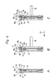
- FIG. 6 in three successive steps A to C. shown assembly of the sealing device 35 is carried out according to the embodiment shown from the side on which the pilot valve 32 is located, ie in a mounting direction 51 from left to right. It is first a first housing element 38a with its attached sealing element 39 inserted into the housing recess 16 until it his reaches predetermined space along the housing recess 16, in the embodiment shown by a gradation 56 is formed on the closure lid 34.
- a gradation 56 is formed on the closure lid 34.
- the seal member 39 to be assembled deforms also not in the channel mouths of the valve channels to be passed into it, which prevents the effect described above.
- the associated second housing member 38b inserted and clamped together with the first housing element, wherein the housing outer portion 44 b of the second Housing member 38b located bead 46 in the outer portion 40 of the sealing element 39 is pressed, so that the outer portion 40 and thus the outer sealing area 41 radially outwardly deformed and a sealing effect against the Wall surface 18 of the housing wall 17 is achieved. simultaneously prevents the between the outer portion 40 and the inner portion 42 trained, across these two sections lying transition portion 47, that the inner portion 42nd mitverformt is.
- On the outside of the sealing element 39 of the second housing member 38b are over the circumference of the second housing element 38b distributes several, in particular three spacers 55, which determine the position of the next, in assembly direction 51 in front of sealing unit 37 set.
- sealing unit 37 a first housing element pushed together with sealing element 39 until it at the Spacer abuts.
- sealing units 37 inserted become.
- the last sealing unit 37 has the second Housing element 38b no spacers 55 more, but expediently toothing means 57, with which this sealing unit 37 fixed in the housing recess 16 and the entire sealing device 35 against withdrawal the mounting direction 51 is locked.
Landscapes
- Engineering & Computer Science (AREA)
- General Engineering & Computer Science (AREA)
- Mechanical Engineering (AREA)
- Multiple-Way Valves (AREA)
- Valve Housings (AREA)
- Magnetically Actuated Valves (AREA)
- Electrically Driven Valve-Operating Means (AREA)
- Temperature-Responsive Valves (AREA)
- Check Valves (AREA)
Abstract
Description
Die Erfindung betrifft ein Ventil mit einem Ventilgehäuse, das eine zur Aufnahme eines Ventilschiebers vorgesehene, umfangsseitig von einer Gehäusewand begrenzte längliche Gehäuseausnehmung aufweist, in die seitlich mindestens ein Ventilkanal einmündet und in der eine vom Ventilschieber durchsetzte Dichtungseinrichtung angeordnet ist, die ein Dichtungs-Gehäuse besitzt, das wenigstens ein ringförmiges Dichtelement hält, das einen Außenabschnitt mit äußerem Dichtbereich zur Abdichtung gegenüber der Gehäuseausnehmung und einen Innenabschnitt mit innerem Dichtbereich zur Abdichtung gegenüber dem Ventilschieber besitzt.The invention relates to a valve with a valve housing, the one provided for receiving a valve spool, circumferentially from a housing wall limited elongated housing recess has, in the laterally at least one valve channel opens and in the one penetrated by the valve spool Seal device is arranged, which is a seal housing has, at least one annular sealing element that holds an outer section with outer sealing area to Seal against the housing recess and an inner portion with inner sealing area for sealing against the Valve slide has.
Ein derartiges Ventil ist beispielsweise aus der DE 41 01 049
C2 bekannt, in der eine Dichtungseinrichtung für ein Mehrwegeventil
beschrieben ist, bei der eine Halterungshülse vorgesehen
ist, die in eine Aufnahme eingeschoben werden kann und
mehrere ringförmige Dichtelemente aufweist, die jeweils sowohl
eine innere Dichtkante zur Abdichtung gegenüber dem Ventilschieber
und eine äußere Dichtkante zur Abdichtung gegenüber
der Gehäuseausnehmung aufweisen.Such a valve is for example from
In der US 2,892,644 ist eine Dichtungsanordnung für ein Kolbenventil offenbart, die kreisförmige, im Querschnitt Y- bzw. I-förmige Dichtelemente besitzt, die zwischen zwei Distanzelementen eingespannt werden und eine Abdichtung einerseits gegenüber der Gehäusewand des Ventilgehäuses sowie andererseits gegenüber dem in der Gehäuseausnehmung des Kolbenventils geführten Kolben bilden.In US 2,892,644 is a seal assembly for a piston valve disclosed, the circular, in cross-section Y- or I-shaped sealing elements has, between two spacer elements be clamped and a seal on the one hand relative to the housing wall of the valve housing and on the other hand relative to that in the housing recess of the piston valve form guided piston.
Aus der DE 30 43 871 ist ein Mehrwegeventil bekannt, mit einem Gehäuse, das eine Gehäuseausnehmung besitzt, in der ein Ventilschieber axial verschieblich gelagert ist. Die als Führungsbohrung bezeichnete Gehäuseausnehmung ist abgestuft, wobei, von der Montageöffnung aus gesehen im Durchmesser kleiner werdende Abschnitte vorgesehen sind. Die jeweiligen Abschnitte der Führungsbohrung sind mit jeweils einer Distanzstück-Dichtring-Kombination, bestehend aus einem Distanzstück und einem ringförmigen Dichtelement bestückbar. Die Dichtelemente dienen sowohl zur Abdichtung gegenüber der Wandung des jeweiligen Führungsbohrungsabschnitts als auch zur Abdichtung gegenüber dem Ventilschieber.From DE 30 43 871 a multi-way valve is known, with a Housing, which has a housing recess in which a Valve slide is mounted axially displaceable. The as a guide hole designated housing recess is stepped, wherein seen from the mounting opening in diameter smaller expectant sections are provided. The respective sections the guide bore are each with a spacer-sealing ring combination, consisting of a spacer and an annular sealing element can be fitted. The sealing elements serve both to seal against the wall of the respective guide bore section as well as for sealing opposite the valve spool.
Aus der DE 32 40 552 A1 ist eine Schieberventildichtung bekannt,
bei der zur Abdichtung gegenüber dem Ventilschieber
und zur Abdichtung gegenüber der Gehäuseausnehmung des Ventilgehäuses
jeweils separate Dichtungen verwendet werden. Zur
Abdichtung gegenüber der Gehäuseausnehmung wird ein O-Ring
verwendet, während die Abdichtung gegenüber dem Ventilschieber
über einen abgewinkelten Dichtungsring erfolgt, dessen
axial verlaufendes Endteil formschlüssig an einem Distanzring
axial verrastet werden kann.From
Ein Problem des zuvor geschilderten Standes der Technik ist die Montage der Dichtungseinrichtung bzw. der Dichtungen in der Gehäuseausnehmung des Ventilgehäuses. In die Gehäuseausnehmung münden seitlich mehrere Ventilkanäle ein, die die ansonsten geschlossene und glatte Wandung der Gehäuseausnehmung unterbrechen, wobei die Mündungsränder der Ventilkanalmündungen relativ scharfkantig ausgebildet sein können. Um eine Dichtwirkung gegenüber der Gehäuseausnehmung zu erzielen, muss die Dichtung im Presssitz an der Gehäusewandung anliegen. Bei herkömmlichen Ventilen ist bereits bei der Montage die endgültige, dichtende Radialposition der Dichtungen vorhanden, so dass die Gefahr besteht, dass die Dichtungen beschädigt werden, wenn sie über scharfkantige Ränder der Ventilkanalmündungen geschoben werden. Um diesem Problem abzuhelfen ist es bereits bekannt, Montagehilfen zu verwenden, die den Dichtungen über den Bereich der einmündenden Ventilkanäle hinweghelfen.A problem of the previously described prior art is the assembly of the sealing device or the seals in the housing recess of the valve housing. In the housing recess open laterally a plurality of valve channels, which otherwise closed and smooth wall of the housing recess interrupt, with the mouth edges of the valve port mouths may be formed relatively sharp. To one To achieve sealing effect against the housing recess, The gasket must be pressed against the housing wall in a press fit. With conventional valves is already during assembly the final sealing radial position of the seals is present so there is a risk that the seals will be damaged when crossing sharp-edged edges of the valve port mouths be pushed. To remedy this problem it is already known to use assembly aids, the seals over the area of the opening valve channels to tide.
Aufgabe der Erfindung ist es ein Ventil der eingangs erwähnten Art zu schaffen, bei dem die Dichteinrichtung einfach, schnell und zuverlässig montierbar ist.The object of the invention is a valve of the aforementioned To create a way in which the sealing device is simple, can be mounted quickly and reliably.
Diese Aufgabe wird durch ein Ventil mit den Merkmalen des unabhängigen Anspruchs 1 gelöst. Weiterbildungen der Erfindung sind in den Unteransprüchen dargestellt.This task is performed by a valve with the characteristics of the independent Claim 1 solved. Further developments of the invention are shown in the subclaims.
Das erfindungsgemäße Ventil zeichnet sich dadurch aus, dass das Dichtungs-Gehäuse im Bereich des Dichtelementes zwei das Dichtelement zwischen sich fixierende, ringförmige Gehäuseelemente aufweist, wobei wenigstens eines der Gehäuseelemente an der dem Außenabschnitt axial zugeordneten Seite über wenigstens ein Beaufschlagungsmittel verfügt, das beim Zusammenspannen der Gehäuseelemente lokal den Außenabschnitt derart beaufschlägt, dass der Außenabschnitt zur Erzielung einer Dichtwirkung radial nach außen gegen die Gehäusewand pressbar ist und wobei wenigstens ein Entkopplungsmittel vorgesehen ist, das bewirkt, dass der Innenabschnitt von den aus der Beaufschlagung des Außenabschnittes resultierenden, nach radial innen gerichteten Kräften entkoppelt ist. The valve according to the invention is characterized in that the seal housing in the region of the sealing element two the Sealing element between itself fixing, annular housing elements wherein at least one of the housing elements at the outer portion axially associated side over at least has a loading means that when clamping together the housing elements locally the outer portion such causes the outer section to achieve a Sealing effect radially outwardly pressed against the housing wall and wherein at least one decoupling means is provided is that causes the inner portion of the from the impingement of the outer portion resulting, radially decoupled inwardly directed forces.
Bei Montage der Dichtungseinrichtung ist noch keine Pressung zwischen der Gehäusewand und den Dichtelementen vorhanden, so dass diese "gefahrlos" über scharfkantige Mündungsränder einmündender Ventilkanäle hinweg gelangen können. Zusätzliche Montagehilfen sind hierfür nicht notwendig. Die Dichtwirkung entfaltet sich vorzugsweise erst dann, wenn das betreffende Dichtelement seine zuvor bestimmte Axialposition entlang der Gehäuseausnehmung erreicht hat und die beiden, das betreffende Dichtelement flankierenden Gehäuseelemente zusammengespannt werden, wobei der Außenabschnitt des Dichtelements radial nach außen gegen die Gehäusewand gepresst wird.When installing the sealing device is still no pressure between the housing wall and the sealing elements, so that this "safe" opening over sharp edges of muzzle Valve channels can get away. additional Mounting aids are not necessary for this. The sealing effect unfolds preferably only when the relevant Sealing element its previously determined axial position along the Housing recess has reached and the two, the relevant Clamping element flanking housing elements clamped together be, wherein the outer portion of the sealing element radially is pressed against the outside of the housing wall.
Das oder die Entkopplungsmittel bewirken zusätzlich zur "Kraft-Entkopplung", dass eine Fertigungstoleranz am äußeren Dichtbereich des Außenabschnitts keinen Einfluss auf den inneren Dichtbereich hat. Es kann also verhindert werden, dass für die Abdichtung gegenüber der Gehäuseausnehmung, die auch als statische Abdichtung mit statischer Dichtkante bezeichnet werden kann, erforderlichen Radialkräfte und/oder Toleranzen nicht auf den Innenabschnitt des Dichtelements übertragen werden, so dass die Abdichtung gegenüber dem Ventilschieber - auch als dynamische Abdichtung mit dynamischer Dichtkante bezeichnet - davon im Wesentlichen unbeeinflusst ist. Es wird also insbesondere das Problem vermieden, dass der innere Dichtbereich bei Beaufschlagung des Außenabschnitts auf den Ventilschieber drückt, was zu einer erhöhten Reibung zwischen Ventilschieber und Dichtelement führen würde, wobei die erhöhte Reibung zu einer Fehlfunktion beim Schalten des Ventils führen könnte.The one or more decoupling effect in addition to "Power decoupling" that a manufacturing tolerance on the outside Sealing area of the outer section does not affect the inner Sealing area has. So it can be prevented that for sealing against the housing recess, which too called static seal with static sealing edge can be, required radial forces and / or tolerances not transferred to the inner portion of the sealing element so that the seal against the valve spool - also called dynamic sealing with dynamic sealing edge - this is essentially unaffected. It will So in particular the problem avoided that the inner Sealing area when exposed to the outer section of the Valve spool presses, resulting in increased friction between Valve spool and sealing element would result, with the increased Friction to a malfunction when switching the valve could lead.
Bei einer Weiterbildung der Erfindung besitzt der Außenabschnitt des Dichtelements eine den äußeren Dichtbereich enthaltende Außenabschnitts-Radialebene und der Innenabschnitt eine den inneren Dichtbereich enthaltende Innenabschnitts-Radialebene. Vorzugsweise ist als Entkopplungsmittel ein zwischen dem Außenabschnitt und Innenabschnitt befindlicher, einerseits mit dem Außenabschnitt und andererseits mit dem Innenabschnitt verbundener, quer zum Außen- und zum Innenabschnitt ausgerichteter Übergangsabschnitt vorgesehen, der bewirkt, dass die Außenabschnitts-Radialebene axial versetzt zur Innenabschnitts-Radialebene angeordnet ist. Das Dichtelement kann also eine abgewinkelte bzw. abgestufte Gestalt aufweisen. Vorzugsweise ist der Übergangsabschnitt im wesentlich senkrecht bzw. im ca. 90° Winkel zum Außen- und zum Innenabschnitt ausgerichtet. Außen- und Innenabschnitt können also im montierten Zustand der Dichtungseinrichtung in radialer Richtung ausgerichtet sein, während der Übergangsabschnitt im wesentlichen in axialer Richtung verläuft.In a further development of the invention, the outer section has of the sealing element containing the outer sealing area Outer section radial plane and the inner section an inner section radial plane containing the inner sealing region. Preferably, a decoupling means is an intermediate the outer portion and inner portion befindlicher, on the one hand with the outer portion and on the other hand with the inner portion connected, transversely to the outer and inner section provided aligned transition section, which causes the outer section radial plane is offset axially is arranged to the inner-section radial plane. The sealing element can therefore have an angled or stepped shape. Preferably, the transition section is essential perpendicular or at approximately 90 ° to the outer and inner sections aligned. Exterior and interior section can so in the assembled state of the sealing device in radial Direction be aligned while the transition section in essentially runs in the axial direction.
Die Gehäuseelemente können an die Form des Dichtelements angepasst sein, beispielsweise können sie Gehäuse-Übergangsabschnitte besitzen, die im montierten Zustand der Dichtungseinrichtung korrespondierend zum Übergangsabschnitt des Dichtelements ausgebildet sind. Die Gehäuseelemente können also ebenfalls abgewinkelt bzw. abgestuft ausgebildet sein.The housing elements can be adapted to the shape of the sealing element For example, they may have housing transition sections own, in the mounted state of the sealing device corresponding to the transition section of the sealing element are formed. The housing elements can so also be formed angled or graded.
Bevorzugt ist radial zwischen dem Übergangsabschnitt des Dichtelements und dem den Übergangsabschnitt radial innen flankierenden Gehäuse-Übergangsabschnitt insbesondere des die Beaufschlagung des Außenabschnitts bewirkenden Gehäuseelements im montierten Zustand der Dichtungseinrichtung ein Freiraum bzw. Spalt ausgebildet. Dies hat den Vorteil, dass sich der Außenabschnitt bei Beaufschlagung durch das oder die Beaufschlagungsmittel am Gehäuseelement radial in beide Richtungen, also sowohl nach radial innen als nach radial außen verformen kann, wobei sich die Verformung nach innen infolge des Entkopplungsmittels nicht auf den Außenabschnitt überträgt. Preferably, radially between the transition portion of Sealing element and the transition section radially inside flanking housing transition section in particular of the Actuation of the outer portion causing housing element in the assembled state of the sealing device Free space or gap formed. This has the advantage that the outer portion when acted upon by the or Beaufschlagungsmittel on the housing element radially in both directions, So both radially inward than radially outward deform, wherein the deformation inward due of the decoupling means does not transfer to the outer portion.
Besonders bevorzugt sind Außenabschnitt, Übergangsabschnitt und Innenabschnitt einstückig miteinander verbunden. Sie können also durch einen einzigen Herstellungsprozess hergestellt werden. In bevorzugter Weise sind Außenabschnitt, Übergangsabschnitt und Innenabschnitt aus demselben Material hergestellt, insbesondere aus Elastomermaterial. Es ist möglich ein solches Dichtelement durch ein Elastomer-Spritzverfahren herzustellen. Vorzugsweise wird thermoplastisches Elastomer verwendet. Es sind jedoch auch andere Elastormerarten einsetzbar.Particularly preferred are outer section, transition section and inner portion integrally connected. You can thus produced by a single manufacturing process become. Preferably, outer portion, transition portion and inner section made of the same material, in particular of elastomeric material. It is possible Such a sealing element by an elastomer injection process manufacture. Preferably, thermoplastic elastomer used. However, other Elastormerarten can be used.
Bei einer Weiterbildung der Erfindung besitzt die Dichteinrichtung wenigstens ein erstes Gehäuseelement, das mittels Haltemitteln insbesondere formschlüssig mit dem Dichtelement verbunden ist und weist wenigstens ein zweites Gehäuseelement auf, das über das wenigstens eine Beaufschlagungsmittel zur Beaufschlagung des Außenabschnitts des Dichtelements verfügt.In a development of the invention, the sealing device has at least a first housing element, by means of Holding means in particular form-fitting with the sealing element is connected and has at least a second housing element on, the on the at least one Loading the outer portion of the sealing element has.
Vorzugsweise ist das Beaufschlagungsmittel einstückig mit dem zweiten Gehäuseelement verbunden. Prinzipiell wäre es jedoch auch möglich das Beaufschlagungsmittel als separates Bauteil auszubilden und am betreffenden Gehäuseelement zu befestigen. In bevorzugter Weise ist als Beaufschlagungsmittel ein ringförmiger Wulst vorgesehen, der von der dem Außenabschnitt des Dichtelements zugeordneten Seite des zweiten Gehäuseelements axial hervorsteht. Beim Zusammenspannen der Gehäuseelemente kann sich der Wulst in den Außenabschnitt "eingraben", so dass dieser radial nach außen auf die Gehäusewand gepresst wird. Der Wulst ist vorzugsweise aus einem im Vergleich zum Außenabschnitt härteren Material hergestellt, so dass die Beaufschlagung des Außenabschnitts eine Verformung des Außenabschnitts und nicht eine Verformung des Wulstes ergibt. Preferably, the biasing means is integral with the connected to the second housing element. In principle, it would be also possible the loading means as a separate component form and attach to the respective housing element. In a preferred manner, a pressurizing means is a ring-shaped Bead provided by the outer portion of the Sealing element associated side of the second housing element protrudes axially. When clamping the housing elements the bead can "dig in" in the outer section, so that this pressed radially outward on the housing wall becomes. The bead is preferably one compared to Exterior section made of harder material, allowing the impingement the outer portion a deformation of the outer portion and does not give a deformation of the bead.
Die Haltemittel, über die das erste Gehäuseelement und das Dichtelement insbesondere formschlüssig miteinander verbunden werden können, sind vorzugsweise an das Dichtelement angeformt. Sie können also einen Teil des Dichtelements bilden. Alternativ wäre es möglich die Haltemittel am Gehäuseelement vorzusehen. In bevorzugter Weise wird das Dichtelement lediglich durch ein einen Formschluss bildende Haltemittel am betreffenden Gehäuseelement gehalten, so dass sich der Außenabschnitt in radiale Richtungen verformen kann, im Gegensatz zu einer vollflächig stoffschlüssigen Verbindung zwischen Dichtelement und Gehäuseelement, bei der das Dichtelement fest und in radiale Richtungen unbeweglich mit dem Gehäuseelement verbunden ist.The holding means, via which the first housing element and the Sealing element in particular positively connected to each other can be, are preferably integrally formed on the sealing element. So you can form part of the sealing element. Alternatively, it would be possible the retaining means on the housing element provided. Preferably, the sealing element is merely by a form-fitting forming holding means on the relevant Housing element held so that the outer portion can deform in radial directions, as opposed to a full-surface cohesive connection between the sealing element and housing element, in which the sealing element firmly and immobile with the housing member in radial directions connected is.
Das erste Gehäuseelement kann an seiner dem ringförmigen Dichtelement abgewandten Rückseite eine ringförmige Nut zur Aufnahme einer korrespondierend dazu ausgebildeten Verankerungspartie des zugeordneten Haltemittels aufweisen, wobei die Nut über in axialer Richtung verlaufende, insbesondere in regelmäßigen Abständen über den Umfang der Nut verteilte, von den Haltemitteln durchgriffene Öffnungen, insbesondere zylindrische Bohrungen, mit der Vorderseite des ersten Gehäuseelements verbunden ist.The first housing member may at its the annular A sealing element facing away from the rear side an annular groove for Receiving a correspondingly formed anchoring section having the associated holding means, wherein the groove over in the axial direction, in particular in periodically distributed over the circumference of the groove, from The holding means through openings, in particular cylindrical Holes, with the front of the first housing element connected is.
Es ist möglich das Dichtelement von der Rückseite des ersten Gehäuseelements her anzuspritzen, wobei plastifiziertes Dichtelementmaterial über die Öffnungen zur Vorderseite gelangen und dort in einer, die Form des Dichtelements vorgebenden Negativform in seine spätere Gestalt erstarren kann.It is possible the sealing element from the back of the first To inject housing element ago, wherein plasticized sealing element material pass through the openings to the front and there in one, the shape of the sealing element predetermining Negative form can solidify into its later form.
Das Dichtungs-Gehäuse kann aus mehreren ersten und mehreren zweiten Gehäuseelementen bestehen, wobei die ersten und/oder zweiten Gehäuseelemente an ihrem dem Dichtelement abgewandten Rückseiten über Abstandshalter bzw. Distanzelemente mit benachbarten ersten oder zweiten Gehäuseelementen gekoppelt sind. Es ist möglich, dass das erste Gehäuseelement über Abstandsschalter mit einem benachbarten zweiten und das zweite Gehäuseelement dementsprechend mit einem benachbarten ersten Gehäuseelement gekoppelt ist. In bevorzugter Weise befinden sich die Abstandshalter lediglich an den Rückseiten der zweiten, das Beaufschlagungsmittel aufweisenden Gehäuseelemente, insbesondere sind die Abstandshalter einstückig mit dem zweiten Gehäuseelement verbunden.The seal housing may consist of several first and several second housing elements, wherein the first and / or second housing elements facing away from the sealing element Rear sides over spacers or spacers with adjacent coupled to first or second housing elements are. It is possible that the first housing element via distance switch with a neighboring second and the second Housing element accordingly with an adjacent first Housing element is coupled. Preferably, located the spacers only on the backs of the second, the loading means having housing elements, In particular, the spacers are integral with the second Housing element connected.
Die ersten und zweiten Gehäuseelemente können aus dem selben Material hergestellt sein, beispielsweise aus Polymermaterial. Es sind jedoch auch andere Werkstoffe einsetzbar, beispielsweise Metalle und/oder Metalllegierungen.The first and second housing elements may be made of the same Material be made, for example, of polymer material. However, other materials can be used, for example Metals and / or metal alloys.
Ein bevorzugtes Ausführungsbeispiel der Erfindung ist in den Zeichnungen dargestellt und wird im folgenden näher erläutert. Die Zeichnungen zeigen:
- Figur 1
- ein bevorzugtes Ausführungsbeispiel des erfindungsgemäßen Ventils im Längsschnitt,
- Figur 2
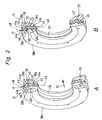
- eine schematische perspektivische, teilweise geschnittene Ansicht zweier Gehäuseelemente mit dazwischen angeordnetem Dichtelement, wobei in Darstellung A der ungespannte und in Darstellung B der gespannte Zustand gezeigt ist,
- Figur 3
- eine perspektivische Ansicht auf ein zweites Gehäuseelement des Dichtungs-Gehäuses des erfindungsgemäßen Ventils,
- Figur 4
- einen Längsschnitt durch das Gehäuseelement von Figur 3,
Figur 5- einen Längsschnitt durch ein erstes Gehäuseelement mit angeformtem Dichtelement und
- Figur 6
- in drei aufeinander folgenden Abbildungen A bis C einen Längsschnitt durch das erste und zweite Gehäuseelement samt Dichtungselement beim Zusammenfügen der Gehäuseelemente.
- FIG. 1
- a preferred embodiment of the valve according to the invention in longitudinal section,
- FIG. 2
- a schematic perspective, partially sectioned view of two housing elements with sealing element arranged therebetween, wherein in illustration A of the untensioned and shown in illustration B the tensioned state,
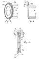
- FIG. 3
- a perspective view of a second housing element of the seal housing of the valve according to the invention,
- FIG. 4
- a longitudinal section through the housing element of Figure 3,
- FIG. 5
- a longitudinal section through a first housing element with molded sealing element and
- FIG. 6
- in three successive figures A to C is a longitudinal section through the first and second housing element together with the sealing element during assembly of the housing elements.
Die Figur 1 zeigt ein Ventil 11 als Bestandteil einer insgesamt
mit Bezugsziffer 12 bezeichneten Ventilanordnung, die
zusätzlich noch über einen bevorzugt plattenartig ausgebildeten
Fluidverteiler 13 verfügt, auf dem das Ventil 11 lösbar,
mittels geeigneten Befestigungsmitteln 14, befestigt ist.FIG. 1 shows a valve 11 as part of a total
designated by
Das Ventil 11 dient zur Steuerung von Fluidströmen und ist als Mehrwegeventil ausgeführt. Bei dem zu steuernden Medium handelt es sich insbesondere um Druckluft, wobei es sich allerdings auch um ein sonstiges gasförmiges oder hydraulisches Medium handeln kann.The valve 11 is used to control fluid flows and is designed as a multi-way valve. In the medium to be controlled it is in particular compressed air, although it is also to another gaseous or hydraulic Medium can act.
Das Ventil 11 verfügt über ein Ventilgehäuse 15, in dem wenigstens
eine sich linear erstreckende, längliche Gehäuseausnehmung
16 vorgesehen ist. Umfangsseitig ist die Gehäuseausnehmung
16 von einer Gehäusewand 17 des Ventilgehäuses 15 begrenzt.The valve 11 has a
Die Gehäusewand 17 und insbesondere das gesamte Ventilgehäuse
15 bestehen beim Ausführungsbeispiel aus Kunststoffmaterial.
Die Herstellung erfolgt zweckmäßigerweise durch Spritzgießen,
wobei ein Nachbearbeiten der die Gehäuseausnehmung 16 definierenden
und nach radial innen orientierten Wandfläche 18
der Gehäusewand 17 nicht oder in nur geringem Maße erforderlich
ist. Eine Bauform aus Metall wäre prinzipiell ebenfalls
möglich. The housing wall 17 and in particular the
In die Gehäuseausnehmung 16 münden im Bereich der Wandfläche
18 an mehreren in der Längsrichtung der Gehäuseausnehmung 16
beabstandeten Stellen Ventilkanäle 19 ein. Diese durchsetzen
die Gehäusewand 17 und bilden an ihrem äußeren Ende Anschlussöffnungen
20. Gemäß bevorzugtem Ausführungsbeispiel
münden drei dieser Anschlussöffnungen zu einer außenliegenden
Montagefläche 21 des Ventilgehäuses 15, mit der das Ventil 11
an einer Bestückungsfläche 22 des Fluidverteilers 13 angesetzt
ist. In letzterem verlaufen mehrere Fluidverteilerkanäle
23, die zur Bestückungsfläche 22 ausmünden und dort mit
den Anschlussöffnungen 20 paarweise kommunizieren.In the housing recess 16 open in the region of the
Gemäß dem Ausführungsbeispiel münden zwei weitere der Anschlussöffnungen
20 an einer der Montagefläche 21 insbesondere
entgegengesetzten Anschlussfläche 24 des Ventilgehäuses 15
und sind dazu vorgesehen, das Anschließen nicht näher dargestellter
Fluidleitungen zu ermöglichen, die zu einem anzusteuernden
Verbraucher führen.According to the embodiment, two more of the connection openings open
20 on one of the mounting
Bei dem Ventil 11 des Ausführungsbeispiels handelt es sich um
ein 4/2-Wegeventil. Es ist jedoch auch denkbar 3/2 oder 5/2-Wegeventile
einzusetzen. Beim gezeigten 4/2-Wegeventil handelt
es sich bei den zur Montagefläche 21 ausmündenden Ventilkanälen
19 um einen mittleren Speisekanal 19a, der axial
von einem Entlüftungskanal 19b flankiert ist. Die beiden zur
Anschlussfläche 24 führenden Ventilkanäle 19 sind Arbeitskanäle
19c und 19d.The valve 11 of the embodiment is
a 4/2-way valve. However, it is also conceivable 3/2 or 5/2-way valves
use. When shown 4/2-way valve acts
it is at the opening to the mounting
Auf dem Fluidverteiler 13 können mehrere Ventile 11 positioniert
sein, die jeweils zuordnungsrichtig mit dem Fluidverteilerkanälen
23 verbunden sind.On the fluid manifold 13 a plurality of valves 11 can be positioned
be, each matching correctly with the
In der Gehäuseausnehmung 16 ist ein länglicher kolbenartiger
Ventilschieber 25 angeordnet. Er verfügt über mehrere Steuerabschnitte
26 größeren Durchmessers, zwischen denen jeweils
ein Steuerabschnitt 27 kleineren Durchmessers plaziert ist.
Dem Ventilschieber 25 zugeordnete Betätigungsmittel ermöglichen
ein axial verlagern und positionieren des ventilschiebers
25 in der Gehäuseausnehmung 16 relativ zum Ventilgehäuse
15.In the housing recess 16 is an elongated piston-like
Valve slide 25 is arranged. He has
Die Betätigungsmittel enthalten beim Ausführungsbeispiel einen
mit dem Ventilschieber 25 einenends in Wirkverbindung
stehenden Antriebskolben 28. Dieser ist in einem als Betätigungsraum
29 bezeichneten Endabschnitt der Gehäuseausnehmung
16 unter Abdichtung verschiebbar geführt.The actuating means include in the embodiment a
with the
Der auf der dem Ventilschieber 25 entgegengesetzten Seite des
Antriebskolbens 28 liegende äußere Abschnitt 30 des Betätigungsraumes
29 kommuniziert auf nicht näher dargestellte Weise
mit einem Steuerkanal 31, über den ein fluidisches Steuermedium
wahlweise zugeführt oder abgeführt werden kann. Die
entsprechende Steuerung übernimmt ein elektrisch aktivierbares
Vorsteuerventil 32 das an das Ventilgehäuse 15 angebaut
ist.The on the
Vergleichbare Betätigungsmittel können auch dem entgegengesetzten
Ende des Ventilschiebers 25 zugeordnet sein. Abweichend
hiervon findet sich dort beim Ausführungsbeispiel allerdings
nur eine Rückstellfeder 33, die zwischen dem Ventilgehäuse
15 und dem Ventilschieber 25 wirksam ist und den Ventilschieber
25 ständig in Richtung zum Antriebskolben beaufschlagt.Comparable actuators may also be the opposite
Be assigned to the end of the
Im deaktivierten Zustand des Vorsteuerventils 32 nimmt der
Ventilschieber 25, bedingt durch die Vorspannung der Rückstellfeder
33, die aus der Zeichnung ersichtliche erste
Schaltstellung ein. Durch Aktivieren des Vorsteuerventils 32
wird der Antriebskolben 28 und somit der Ventilschieber 25
unter gleichzeitiger Komprimierung der Rückstellfeder 33 nach
rechts in eine zweite Schaltstellung verlagert.In the deactivated state of the
Die Gehäuseausnehmung 16 ist an beiden Stirnseiten geschlossen.
An wenigstens einer Stirnseite erfolgt der Verschluss
durch einen lösbar am Ventilgehäuse 15 befestigten Verschlussdeckel
34. Im entfernten Zustand des Verschlussdeckels
34 ist die Gehäuseausnehmung 16 von der entsprechenden Stirnseite
her zugänglich.The housing recess 16 is closed at both end sides.
On at least one front side of the closure takes place
by a cover plate detachably fastened to the
In der Gehäuseausnehmung 16 befindet sich eine zwischen dem
Ventilschieber 25 und der Gehäusewand 17 wirksame Dichtungseinrichtung
35. Sie sitzt koaxial zwischen der Wandfläche 18
und dem Ventilschieber 25, wobei sie von letzterem koaxial
durchsetzt wird.In the housing recess 16 is located between the
Die Dichtungseinrichtung besitzt ein Dichtungsgehäuse 36, das
seinerseits aus mindestens einer, vorzugsweise aus mehreren
Dichtungseinheiten 37 aufgebaut ist, wobei gemäß dem Ausführungsbeispiel
vier bzw. fünf Dichtungseinheiten 37 vorhanden
sind.The sealing device has a
Wie insbesondere in Figur 2 dargestellt, ist eine Dichtungseinheit
37 jeweils aus einem ersten, ringförmigen Gehäuseelement
38a und einem in axialer Richtung benachbarten zweiten,
ringförmigen Gehäuseelement 38b aufgebaut, wobei zwischen dem
ersten und zweiten Gehäuseelement 38a, 38b ein ringförmiges
Dichtelement 39 fixiert ist.As shown in particular in Figure 2, is a sealing
Das Dichtelement 39 besteht aus einem Außenabschnitt 40 mit
äußerem Dichtbereich 41 zur Abdichtung gegenüber der Gehäuseausnehmung
16 und einen Innenabschnitt 42 mit innerem Dichtbereich
43 zur Abdichtung gegenüber dem Ventilschieber 25. The sealing
Im montierten Zustand der Dichtungseinrichtung 35 ist der Außenabschnitt
40 zwischen zwei zugeordneten Gehäuse-Außenabschnitten
44a, 44b der beiden Gehäuseelemente 38a, 38b fixiert,
während dem Innenabschnitt 42 Gehäuse-Innenabschnitte
45a, 45b der beiden Gehäuseelemente 38a, 38b zugeordnet sind.In the assembled state of the sealing
An mindestens einem der Gehäuse-Außenabschnitte 44a, 44b,
insbesondere am Gehäuse-Außenabschnitt 44b des zweiten Gehäuseelements
38b, das auch als Spannteil bezeichnet werden
kann, befindet sich wenigstens ein Beaufschlagungsmittel 46,
das den Außenabschnitt 40 des Dichtelements 39 derart beaufschlägt,
dass der Außenabschnitt 40 und damit der äußere
Dichtbereich 41 zur Erzielung einer Dichtwirkung radial nach
außen gegen die Gehäusewand 17 gepresst wird.At least one of the
Das Beaufschlagungsmittel ist beispielhaft in Form eines am
Gehäuse-Außenabschnitt 44b des zweiten Gehäuseelements 38b
befindlichen, ringförmigen, zum zu beaufschlagenden Dichtelement
39 hin weisenden Wulstes 46 dargestellt. Der Wulst 46
kann beim Zusammenspannen der Gehäuseelemente in den Außenabschnitt
40 eindringen, so dass sich der Außenabschnitt nach
radial außen verformt, womit eine Dichtwirkung gegenüber der
Gehäuseausnehmung 16 erreicht wird. Es ist selbstverständlich
auch möglich Beaufschlagungsmittel an beiden Gehäuseelementen
38a, 38b vorzusehen, beispielsweise zwei sich gegenüberliegende
Wülste 46 vorzusehen, zwischen denen der Außenabschnitt
40 des Dichtelements 39 eingespannt ist. Eine Alternative
ist, ein Beaufschlagungsmittel am ersten Gehäuseelement vorzusehen.The Beaufschlagungsmittel is exemplified in the form of an am
Housing
Das Dichtelement 39 besitzt ferner wenigstens ein Entkopplungsmittel
47, das bewirkt, dass der Innenabschnitt 42 des
Dichtelements 39 von den aus der Beaufschlagung des Außenabschnitts
40 resultierenden, nach radial innen gerichteten
Kräften entkoppelt ist. Das Entkopplungsmittel ist beispielhaft
anhand eines Übergangsabschnitts 47 dargestellt, der
quer zum Außen- und zum Innenabschnitt 40, 41 des Dichtelements
39 angeordnet ist und einenends mit dem Außenabschnitt
40 und andernends mit dem Innenabschnitt 41 verbunden ist.
Durch den Übergangsabschnitt 47 wird erreicht, dass die Außenabschnitts-Radialebene
48 des Außenabschnitts 40, die den
äußeren Dichtbereich enthält axial versetzt zur Innenabschnitts-Radialebene
49 des Innenabschnitts, die den inneren
Dichtbereich enthält, angeordnet ist. Eine Beaufschlagung des
Außenabschnitts und eine insbesondere damit verbundene Bewegung
desselbigen nach radial innen, wird also durch den Übergangsabschnitt
47 aufgefangen und nicht auf den Innenabschnitt
42 übertragen, so dass dort keine Bewegung nach radial
innen erfolgt. Eine Bewegung des Dichtelements 39 nach radial
innen ist unerwünscht, da dadurch zusätzlich Reibung
zwischen dem inneren Dichtbereich 43 und dem Ventilschieber
25 entstehen könnte, was zu erhöhtem Verschleiß des Dichtelements
39 und/oder zu einer Beeinträchtigung der Schaltfunktion
des Ventils 11 führen könnte.The sealing
Das Dichtelement 39 hat insgesamt die Gestalt eines abgesetzten
bzw. abgestuften Dichtungsrings, wobei Außenabschnitt,
Übergangsabschnitt und Innenabschnitt 40, 42, 47 einstückig
miteinander verbunden sind und durch einen einzigen Dichtelement-Herstellungsprozeß
hergestellt werden können. Das Dichtelement
39 besteht aus einem relativ weichen Elastomermaterial,
das vorzugsweise weicher ist, als der Wulst 46 am zweiten
Gehäuseelement 38b, so dass dieser beim Zusammenspannen
der Gehäuseelemente 38a, 38b in das weiche Elastomermaterial
eindringen und den Außenabschnitt 40 verformen kann, so dass
der äußere Dichtbereich 41 gegen die Wandfläche 18 der Gehäusewand
17 gepresst wird. Als Elastomermaterial kann beispielsweise
ein thermoplastisches Elastomer eingesetzt werden. The sealing
Während das zweite Gehäuseelement 38b mit seinem Wulst 46 zum
Beaufschlagen bzw. Spannen des Dichtelements 39 dient, ist
das erste Gehäuseelement 38a, das auch als Trägerteil bezeichnet
werden kann, zum Tragen des Dichtelements 39 bestimmt.
Die Befestigung des Dichtelements 39 am ersten Gehäuseelement
38a erfolgt über Haltemittel 50, die einen Formschluss
zwischen Dichtelement 39 und erstem Gehäuseelement
38a bilden, so dass das Dichtelement 39 entgegen einer Montagerichtung
51 nicht wieder vom ersten Gehäuseelement 38a abgezogen
werden kann.While the
Die Haltemittel 50 werden vom Dichtelement 39 selbst gebildet,
insbesondere werden sie bei der Herstellung des Dichtelements
39 mit angeformt. Zweckmäßigerweise ist das erste Gehäuseelement
38a derart ausgebildet, dass das Dichtelement 39
daran angeformt, vorzugsweise mittels eines Spritzprozesses,
beispielsweise mittels eines Elastomer-Spritzgießverfahrens
daran angespritzt werden kann.The holding means 50 are formed by the sealing
Wie insbesondere in Figur 5 dargestellt besitzt das erste Gehäuseelement
38a an seiner dem Dichtelement 39 gegenüberliegenden
Rückseite eine ringförmige, umlaufende Nut 52, an deren
Nutgrund Öffnungen 53 vorgesehen sind, die an der Vorderseite
des ersten Gehäuseelements 38a ausmünden. Die ringförmige
Nut 52 und die Öffnungen 53, die vorzugsweise als Bohrungen
mit kreisrundem Querschnitt ausgebildet sind, dienen
zur Aufnahme von Verankerungspartien 54 der Haltemittel 50.
Es ist beispielsweise möglich das Dichtelement 39 von der
Rückseite des ersten Gehäuseelements 38a her zunächst die
ringförmige Nut 52 füllend anzuspritzen, so dass plastifiziertes
Dichtelement-Material über die Öffnungen 53 zur Innenseite
gelangt und dort ein in einer die Gestalt des Dichtelements
39 vorgebenden Negativform aufgenommen wird und
dort zu seiner endgültigen Gestalt erstarrt. As shown in particular in FIG. 5, the first housing element has
38 a at its the
Die einzelnen Dichtungseinheiten 37 der Dichtungseinrichtung
35 sind in regelmäßigen Abständen entlang der Gehäuseausnehmung
16 des Ventilgehäuses 15 angeordnet. Dieser regelmäßige
Abstand wird durch Abstandshalter bzw. Distanzelemente 55 erreicht,
die vorzugsweise an der dem Dichtelement39 abgewandten
Außenseite des zweiten Gehäuseelements 38b befestigt
sind.The
Wie in Figur 6 in drei aufeinanderfolgenden Schritten A bis C
dargestellt erfolgt die Montage der Dichtungseinrichtung 35
gemäß dem gezeigten Ausführungsbeispiel von der Seite, an dem
sich das Vorsteuerventil 32 befindet, also in einer Montagerichtung
51 von links nach rechts. Dabei wird zunächst ein
erstes Gehäuseelement 38a samt daran befestigtem Dichtelement
39 in die Gehäuseausnehmung 16 eingeschoben, bis es seinen
vorbestimmten Platz entlang der Gehäuseausnehmung 16 erreicht,
der im gezeigten Ausführungsbeispiel durch eine Abstufung
56 am Verschlußdeckel 34 gebildet wird. Beim Einschieben
des ersten Gehäuseelements 38a mitsamt dem Dichtelement
39 werden die seitlich in die Gehäuseausnehmung 16 einmündenden
Ventilkanäle 19a bis 19d passiert. Bei herkömmlichen
Dichtungseinrichtungen deren Dichtungselemente bereits
beim Montieren press an der Gehäusewand 17 anliegen, entspannen
sich die Dichtungselemente, wenn sie über die Mündungen
der Ventilkanäle gedrückt werden. Dies hat zur Folge, dass
sich das elastische Gummi-Dichtelementmaterial etwas in die
Mündungen hineinverformt. Wird die Dichtungseinrichtung 35
nun in Montagerichtung 51 weitergedrückt bleibt der in die
Mündung hineinverformte Abschnitt des Dichtelements am Rand
der Mündung hängen, was zur Beschädigung des Dichtelements
führen kann. Beim erfindungsgemäßen Ventil 11 ist das Dichtelement
39 während des Montierens nicht unter Spannung, das
heißt, es wird noch nicht gegen die Wandfläche 18 der Gehäuseausnehmung
6 gepreßt. Die Dichtwirkung wird erst mit dem
Zusammenspannen der beiden Gehäuseelemente 38a, 38b erzeugt. As in Figure 6 in three successive steps A to C.
shown assembly of the sealing
Folglich verformt sich das zu montierende Dichtelement 39
auch nicht in die Kanalmündungen der zu passierenden Ventilkanäle
hinein, was den zuvor beschriebenen Effekt verhindert.As a result, the
Als nächstes wird das dazugehörige, zweite Gehäuseelement 38b
eingeschoben und mit dem ersten Gehäuseelement zusammengespannt,
wobei der am Gehäuse-Aussenabschnitt 44b des zweiten
Gehäuseelements 38b befindliche Wulst 46 in den Außenabschnitt
40 des Dichtelements 39 eingedrückt wird, so dass
sich der Außenabschnitt 40 und somit der äußere Dichtbereich
41 radial außen verformt und eine Dichtwirkung gegenüber der
Wandfläche 18 der Gehäusewand 17 erzielt wird. Gleichzeitig
verhindert der zwischen dem Außenabschnitt 40 und dem Innenabschnitt
42 ausgebildete, quer zu diesen beiden Abschnitten
liegende Übergangsabschnitt 47, dass der Innenabschnitt 42
mitverformt wird. An der dem Dichtelement 39 abgewandten Außenseite
des zweiten Gehäuseelements 38b befinden sich über
den Umfang des zweiten Gehäuseelements 38b verteilt mehrere,
insbesondere drei Abstandshalter 55, die die Lage der nächsten,
in Montagerichtung 51 davor liegenden Dichtungseinheit
37 festlegen. Als nächstes wird dann wiederum ein erstes Gehäuseelement
samt Dichtelement 39 eingeschoben, bis es an den
Abstandshalter anstößt. So können nach und nach mehrere, im
Ausführungsbeispiel fünf, Dichtungseinheiten 37 eingeschoben
werden. Bei der letzten Dichtungseinheit 37 besitzt das zweite
Gehäuseelement 38b keinen Abstandshalter 55 mehr, sondern
zweckmäßigerweise Verzahnungsmittel 57, mit der diese Dichtungseinheit
37 in der Gehäuseausnehmung 16 festgelegt und
die gesamte Dichtungseinrichtung 35 gegen Herausziehen entgegen
der Montagerichtung 51 verrastet wird.Next, the associated
Claims (17)
Applications Claiming Priority (2)
| Application Number | Priority Date | Filing Date | Title |
|---|---|---|---|
| DE102004007091 | 2004-02-13 | ||
| DE102004007091A DE102004007091B3 (en) | 2004-02-13 | 2004-02-13 | Valve for fluid system has seal housing with two housing elements in region of sealing element |
Publications (2)
| Publication Number | Publication Date |
|---|---|
| EP1564458A1 true EP1564458A1 (en) | 2005-08-17 |
| EP1564458B1 EP1564458B1 (en) | 2008-09-24 |
Family
ID=34684036
Family Applications (1)
| Application Number | Title | Priority Date | Filing Date |
|---|---|---|---|
| EP05001872A Expired - Lifetime EP1564458B1 (en) | 2004-02-13 | 2005-01-29 | Valve |
Country Status (4)
| Country | Link |
|---|---|
| EP (1) | EP1564458B1 (en) |
| AT (1) | ATE409296T1 (en) |
| DE (2) | DE102004007091B3 (en) |
| ES (1) | ES2311886T3 (en) |
Cited By (1)
| Publication number | Priority date | Publication date | Assignee | Title |
|---|---|---|---|---|
| WO2010003608A1 (en) * | 2008-07-11 | 2010-01-14 | Knorr-Bremse Systeme für Nutzfahrzeuge GmbH | Valve having a long average operating life |
Citations (3)
| Publication number | Priority date | Publication date | Assignee | Title |
|---|---|---|---|---|
| US2892644A (en) * | 1954-06-18 | 1959-06-30 | Int Basic Economy Corp | Packing means for plunger valves |
| DE1287878B (en) * | 1969-01-23 | Hoerbiger Ventilwerke Ag, Wien | Device for sealing axially displaceable control pistons, rods and the like | |
| US3451430A (en) * | 1966-11-16 | 1969-06-24 | Lloyd D Cowdin | Fluid control valve |
Family Cites Families (3)
| Publication number | Priority date | Publication date | Assignee | Title |
|---|---|---|---|---|
| DE3043871A1 (en) * | 1980-11-21 | 1982-07-08 | Wabco Steuerungstechnik GmbH & Co, 3000 Hannover | MULTI-WAY VALVE |
| DE3240552C2 (en) * | 1982-11-03 | 1986-08-28 | Prädifa Präzisions-Dichtungs-Fabrik GmbH, 7120 Bietigheim-Bissingen | Spool valve seal |
| DE4101049C2 (en) * | 1991-01-16 | 1997-08-21 | Miele & Cie | Telescopic suction pipe of a vacuum cleaner |
-
2004
- 2004-02-13 DE DE102004007091A patent/DE102004007091B3/en not_active Expired - Fee Related
-
2005
- 2005-01-29 EP EP05001872A patent/EP1564458B1/en not_active Expired - Lifetime
- 2005-01-29 DE DE502005005438T patent/DE502005005438D1/en not_active Expired - Lifetime
- 2005-01-29 ES ES05001872T patent/ES2311886T3/en not_active Expired - Lifetime
- 2005-01-29 AT AT05001872T patent/ATE409296T1/en not_active IP Right Cessation
Patent Citations (3)
| Publication number | Priority date | Publication date | Assignee | Title |
|---|---|---|---|---|
| DE1287878B (en) * | 1969-01-23 | Hoerbiger Ventilwerke Ag, Wien | Device for sealing axially displaceable control pistons, rods and the like | |
| US2892644A (en) * | 1954-06-18 | 1959-06-30 | Int Basic Economy Corp | Packing means for plunger valves |
| US3451430A (en) * | 1966-11-16 | 1969-06-24 | Lloyd D Cowdin | Fluid control valve |
Cited By (1)
| Publication number | Priority date | Publication date | Assignee | Title |
|---|---|---|---|---|
| WO2010003608A1 (en) * | 2008-07-11 | 2010-01-14 | Knorr-Bremse Systeme für Nutzfahrzeuge GmbH | Valve having a long average operating life |
Also Published As
| Publication number | Publication date |
|---|---|
| DE102004007091B3 (en) | 2005-07-28 |
| DE502005005438D1 (en) | 2008-11-06 |
| EP1564458B1 (en) | 2008-09-24 |
| ATE409296T1 (en) | 2008-10-15 |
| ES2311886T3 (en) | 2009-02-16 |
Similar Documents
| Publication | Publication Date | Title |
|---|---|---|
| EP1291563B1 (en) | Check valve and valve with such a check valve | |
| DE69601132T2 (en) | GAS VALVE FOR PROVIDING A GAS PULSE | |
| DE69708991T2 (en) | Shuttle valve with means to avoid counterflow | |
| DE69702683T2 (en) | Pneumatically operated device | |
| DE102009047261B3 (en) | Dämpfventileinrichtung with a multi-stage Dämpfkraftkennlinie | |
| DE102016220855B4 (en) | Valve slide and valve equipped with it | |
| EP2924327B1 (en) | Multi-port valve | |
| DE102015204547A1 (en) | Control piston of a multiway valve and thus equipped multiway valve | |
| EP3167213B1 (en) | Pinch valve | |
| DE102019211004A1 (en) | Valve | |
| EP4073407B1 (en) | Device for holding a stem of a hydraulic cylinder in position, and method for unblocking and blocking a secondary check valve of the device | |
| DE29604707U1 (en) | Partitioning device for a pressure medium channel | |
| DE102019200784B4 (en) | check valve | |
| DE102015003062B4 (en) | Multi-way valve | |
| DE19725999C1 (en) | Plug connection device and fluid distribution device equipped with one or more plug connection devices | |
| EP1564458B1 (en) | Valve | |
| DE3204112A1 (en) | Servo spool valve | |
| DE2449443A1 (en) | Cartridge type back pressure valve - consists of threaded section with internal valve body and rear ring seal | |
| DE202005016282U1 (en) | Valve unit, has closure head and compression spring unit that are compressed axially to form single piece construction unit, and actuator lifting head by compressing compression spring unit so that flowing of flow-medium takes place | |
| DE102017110716B3 (en) | Piston-cylinder arrangement for a clutch or brake system and clutch with a piston-cylinder arrangement | |
| DE102009056496A1 (en) | Throttle valve for use in fluid-operated working cylinder, has valve whose mounting membrane is fixed to fastening sleeve and supporting throttle body such that membrane has elastic deformation while changing throttle position of body | |
| EP1517072B1 (en) | Valve | |
| DE4119402A1 (en) | SLIDE VALVE | |
| DE102016220857B4 (en) | Valve slide and valve equipped with it | |
| DE2523667A1 (en) | VALVE, IN PARTICULAR PNEUMATIC DELAY VALVE |
Legal Events
| Date | Code | Title | Description |
|---|---|---|---|
| PUAI | Public reference made under article 153(3) epc to a published international application that has entered the european phase |
Free format text: ORIGINAL CODE: 0009012 |
|
| AK | Designated contracting states |
Kind code of ref document: A1 Designated state(s): AT BE BG CH CY CZ DE DK EE ES FI FR GB GR HU IE IS IT LI LT LU MC NL PL PT RO SE SI SK TR |
|
| AX | Request for extension of the european patent |
Extension state: AL BA HR LV MK YU |
|
| 17P | Request for examination filed |
Effective date: 20050707 |
|
| AKX | Designation fees paid |
Designated state(s): AT BE BG CH CY CZ DE DK EE ES FI FR GB GR HU IE IS IT LI LT LU MC NL PL PT RO SE SI SK TR |
|
| GRAP | Despatch of communication of intention to grant a patent |
Free format text: ORIGINAL CODE: EPIDOSNIGR1 |
|
| RAP1 | Party data changed (applicant data changed or rights of an application transferred) |
Owner name: FESTO AG & CO. KG |
|
| GRAS | Grant fee paid |
Free format text: ORIGINAL CODE: EPIDOSNIGR3 |
|
| GRAA | (expected) grant |
Free format text: ORIGINAL CODE: 0009210 |
|
| AK | Designated contracting states |
Kind code of ref document: B1 Designated state(s): AT BE BG CH CY CZ DE DK EE ES FI FR GB GR HU IE IS IT LI LT LU MC NL PL PT RO SE SI SK TR |
|
| REG | Reference to a national code |
Ref country code: GB Ref legal event code: FG4D Free format text: NOT ENGLISH |
|
| REG | Reference to a national code |
Ref country code: CH Ref legal event code: EP |
|
| REG | Reference to a national code |
Ref country code: IE Ref legal event code: FG4D Free format text: LANGUAGE OF EP DOCUMENT: GERMAN |
|
| REF | Corresponds to: |
Ref document number: 502005005438 Country of ref document: DE Date of ref document: 20081106 Kind code of ref document: P |
|
| PG25 | Lapsed in a contracting state [announced via postgrant information from national office to epo] |
Ref country code: LT Free format text: LAPSE BECAUSE OF FAILURE TO SUBMIT A TRANSLATION OF THE DESCRIPTION OR TO PAY THE FEE WITHIN THE PRESCRIBED TIME-LIMIT Effective date: 20080924 |
|
| REG | Reference to a national code |
Ref country code: ES Ref legal event code: FG2A Ref document number: 2311886 Country of ref document: ES Kind code of ref document: T3 |
|
| PG25 | Lapsed in a contracting state [announced via postgrant information from national office to epo] |
Ref country code: SI Free format text: LAPSE BECAUSE OF FAILURE TO SUBMIT A TRANSLATION OF THE DESCRIPTION OR TO PAY THE FEE WITHIN THE PRESCRIBED TIME-LIMIT Effective date: 20080924 Ref country code: FI Free format text: LAPSE BECAUSE OF FAILURE TO SUBMIT A TRANSLATION OF THE DESCRIPTION OR TO PAY THE FEE WITHIN THE PRESCRIBED TIME-LIMIT Effective date: 20080924 |
|
| NLV1 | Nl: lapsed or annulled due to failure to fulfill the requirements of art. 29p and 29m of the patents act | ||
| REG | Reference to a national code |
Ref country code: IE Ref legal event code: FD4D |
|
| PG25 | Lapsed in a contracting state [announced via postgrant information from national office to epo] |
Ref country code: BG Free format text: LAPSE BECAUSE OF FAILURE TO SUBMIT A TRANSLATION OF THE DESCRIPTION OR TO PAY THE FEE WITHIN THE PRESCRIBED TIME-LIMIT Effective date: 20081224 |
|
| PG25 | Lapsed in a contracting state [announced via postgrant information from national office to epo] |
Ref country code: SK Free format text: LAPSE BECAUSE OF FAILURE TO SUBMIT A TRANSLATION OF THE DESCRIPTION OR TO PAY THE FEE WITHIN THE PRESCRIBED TIME-LIMIT Effective date: 20080924 Ref country code: RO Free format text: LAPSE BECAUSE OF FAILURE TO SUBMIT A TRANSLATION OF THE DESCRIPTION OR TO PAY THE FEE WITHIN THE PRESCRIBED TIME-LIMIT Effective date: 20080924 Ref country code: PT Free format text: LAPSE BECAUSE OF FAILURE TO SUBMIT A TRANSLATION OF THE DESCRIPTION OR TO PAY THE FEE WITHIN THE PRESCRIBED TIME-LIMIT Effective date: 20090224 Ref country code: NL Free format text: LAPSE BECAUSE OF FAILURE TO SUBMIT A TRANSLATION OF THE DESCRIPTION OR TO PAY THE FEE WITHIN THE PRESCRIBED TIME-LIMIT Effective date: 20080924 Ref country code: IS Free format text: LAPSE BECAUSE OF FAILURE TO SUBMIT A TRANSLATION OF THE DESCRIPTION OR TO PAY THE FEE WITHIN THE PRESCRIBED TIME-LIMIT Effective date: 20090124 Ref country code: CZ Free format text: LAPSE BECAUSE OF FAILURE TO SUBMIT A TRANSLATION OF THE DESCRIPTION OR TO PAY THE FEE WITHIN THE PRESCRIBED TIME-LIMIT Effective date: 20080924 |
|
| PG25 | Lapsed in a contracting state [announced via postgrant information from national office to epo] |
Ref country code: IE Free format text: LAPSE BECAUSE OF FAILURE TO SUBMIT A TRANSLATION OF THE DESCRIPTION OR TO PAY THE FEE WITHIN THE PRESCRIBED TIME-LIMIT Effective date: 20080924 Ref country code: EE Free format text: LAPSE BECAUSE OF FAILURE TO SUBMIT A TRANSLATION OF THE DESCRIPTION OR TO PAY THE FEE WITHIN THE PRESCRIBED TIME-LIMIT Effective date: 20080924 Ref country code: DK Free format text: LAPSE BECAUSE OF FAILURE TO SUBMIT A TRANSLATION OF THE DESCRIPTION OR TO PAY THE FEE WITHIN THE PRESCRIBED TIME-LIMIT Effective date: 20080924 |
|
| PLBE | No opposition filed within time limit |
Free format text: ORIGINAL CODE: 0009261 |
|
| STAA | Information on the status of an ep patent application or granted ep patent |
Free format text: STATUS: NO OPPOSITION FILED WITHIN TIME LIMIT |
|
| PG25 | Lapsed in a contracting state [announced via postgrant information from national office to epo] |
Ref country code: MC Free format text: LAPSE BECAUSE OF NON-PAYMENT OF DUE FEES Effective date: 20090131 |
|
| REG | Reference to a national code |
Ref country code: CH Ref legal event code: PL |
|
| 26N | No opposition filed |
Effective date: 20090625 |
|
| PG25 | Lapsed in a contracting state [announced via postgrant information from national office to epo] |
Ref country code: LI Free format text: LAPSE BECAUSE OF NON-PAYMENT OF DUE FEES Effective date: 20090131 Ref country code: CH Free format text: LAPSE BECAUSE OF NON-PAYMENT OF DUE FEES Effective date: 20090131 |
|
| PG25 | Lapsed in a contracting state [announced via postgrant information from national office to epo] |
Ref country code: SE Free format text: LAPSE BECAUSE OF FAILURE TO SUBMIT A TRANSLATION OF THE DESCRIPTION OR TO PAY THE FEE WITHIN THE PRESCRIBED TIME-LIMIT Effective date: 20081224 |
|
| PG25 | Lapsed in a contracting state [announced via postgrant information from national office to epo] |
Ref country code: BE Free format text: LAPSE BECAUSE OF NON-PAYMENT OF DUE FEES Effective date: 20090131 |
|
| PG25 | Lapsed in a contracting state [announced via postgrant information from national office to epo] |
Ref country code: PL Free format text: LAPSE BECAUSE OF FAILURE TO SUBMIT A TRANSLATION OF THE DESCRIPTION OR TO PAY THE FEE WITHIN THE PRESCRIBED TIME-LIMIT Effective date: 20080924 |
|
| PG25 | Lapsed in a contracting state [announced via postgrant information from national office to epo] |
Ref country code: AT Free format text: LAPSE BECAUSE OF NON-PAYMENT OF DUE FEES Effective date: 20090129 |
|
| PG25 | Lapsed in a contracting state [announced via postgrant information from national office to epo] |
Ref country code: GR Free format text: LAPSE BECAUSE OF FAILURE TO SUBMIT A TRANSLATION OF THE DESCRIPTION OR TO PAY THE FEE WITHIN THE PRESCRIBED TIME-LIMIT Effective date: 20081225 |
|
| PG25 | Lapsed in a contracting state [announced via postgrant information from national office to epo] |
Ref country code: LU Free format text: LAPSE BECAUSE OF NON-PAYMENT OF DUE FEES Effective date: 20090129 |
|
| PG25 | Lapsed in a contracting state [announced via postgrant information from national office to epo] |
Ref country code: HU Free format text: LAPSE BECAUSE OF FAILURE TO SUBMIT A TRANSLATION OF THE DESCRIPTION OR TO PAY THE FEE WITHIN THE PRESCRIBED TIME-LIMIT Effective date: 20090325 |
|
| PG25 | Lapsed in a contracting state [announced via postgrant information from national office to epo] |
Ref country code: TR Free format text: LAPSE BECAUSE OF FAILURE TO SUBMIT A TRANSLATION OF THE DESCRIPTION OR TO PAY THE FEE WITHIN THE PRESCRIBED TIME-LIMIT Effective date: 20080924 |
|
| PG25 | Lapsed in a contracting state [announced via postgrant information from national office to epo] |
Ref country code: CY Free format text: LAPSE BECAUSE OF FAILURE TO SUBMIT A TRANSLATION OF THE DESCRIPTION OR TO PAY THE FEE WITHIN THE PRESCRIBED TIME-LIMIT Effective date: 20080924 |
|
| PGFP | Annual fee paid to national office [announced via postgrant information from national office to epo] |
Ref country code: ES Payment date: 20150122 Year of fee payment: 11 |
|
| REG | Reference to a national code |
Ref country code: FR Ref legal event code: PLFP Year of fee payment: 12 |
|
| REG | Reference to a national code |
Ref country code: FR Ref legal event code: PLFP Year of fee payment: 13 |
|
| PGFP | Annual fee paid to national office [announced via postgrant information from national office to epo] |
Ref country code: GB Payment date: 20161222 Year of fee payment: 13 |
|
| REG | Reference to a national code |
Ref country code: ES Ref legal event code: FD2A Effective date: 20170227 |
|
| PG25 | Lapsed in a contracting state [announced via postgrant information from national office to epo] |
Ref country code: ES Free format text: LAPSE BECAUSE OF NON-PAYMENT OF DUE FEES Effective date: 20160130 |
|
| REG | Reference to a national code |
Ref country code: FR Ref legal event code: PLFP Year of fee payment: 14 |
|
| GBPC | Gb: european patent ceased through non-payment of renewal fee |
Effective date: 20180129 |
|
| PG25 | Lapsed in a contracting state [announced via postgrant information from national office to epo] |
Ref country code: GB Free format text: LAPSE BECAUSE OF NON-PAYMENT OF DUE FEES Effective date: 20180129 |
|
| PGFP | Annual fee paid to national office [announced via postgrant information from national office to epo] |
Ref country code: IT Payment date: 20190121 Year of fee payment: 15 Ref country code: FR Payment date: 20190122 Year of fee payment: 15 |
|
| REG | Reference to a national code |
Ref country code: DE Ref legal event code: R082 Ref document number: 502005005438 Country of ref document: DE Representative=s name: PATENTANWAELTE MAGENBAUER & KOLLEGEN PARTNERSC, DE Ref country code: DE Ref legal event code: R081 Ref document number: 502005005438 Country of ref document: DE Owner name: FESTO AG & CO. KG, DE Free format text: FORMER OWNER: FESTO AG & CO. KG, 73734 ESSLINGEN, DE Ref country code: DE Ref legal event code: R081 Ref document number: 502005005438 Country of ref document: DE Owner name: FESTO SE & CO. KG, DE Free format text: FORMER OWNER: FESTO AG & CO. KG, 73734 ESSLINGEN, DE |
|
| PGFP | Annual fee paid to national office [announced via postgrant information from national office to epo] |
Ref country code: DE Payment date: 20191214 Year of fee payment: 16 |
|
| PG25 | Lapsed in a contracting state [announced via postgrant information from national office to epo] |
Ref country code: FR Free format text: LAPSE BECAUSE OF NON-PAYMENT OF DUE FEES Effective date: 20200131 |
|
| PG25 | Lapsed in a contracting state [announced via postgrant information from national office to epo] |
Ref country code: IT Free format text: LAPSE BECAUSE OF NON-PAYMENT OF DUE FEES Effective date: 20200129 |
|
| REG | Reference to a national code |
Ref country code: DE Ref legal event code: R119 Ref document number: 502005005438 Country of ref document: DE |
|
| PG25 | Lapsed in a contracting state [announced via postgrant information from national office to epo] |
Ref country code: DE Free format text: LAPSE BECAUSE OF NON-PAYMENT OF DUE FEES Effective date: 20210803 |