EP1564366B1 - Procédé de pose de tuyaux plastiques sans excavation - Google Patents
Procédé de pose de tuyaux plastiques sans excavation Download PDFInfo
- Publication number
- EP1564366B1 EP1564366B1 EP05002689A EP05002689A EP1564366B1 EP 1564366 B1 EP1564366 B1 EP 1564366B1 EP 05002689 A EP05002689 A EP 05002689A EP 05002689 A EP05002689 A EP 05002689A EP 1564366 B1 EP1564366 B1 EP 1564366B1
- Authority
- EP
- European Patent Office
- Prior art keywords
- plastic pipe
- plastic
- pipe
- laying
- conductor
- Prior art date
- Legal status (The legal status is an assumption and is not a legal conclusion. Google has not performed a legal analysis and makes no representation as to the accuracy of the status listed.)
- Expired - Lifetime
Links
Images
Classifications
-
- E—FIXED CONSTRUCTIONS
- E21—EARTH OR ROCK DRILLING; MINING
- E21B—EARTH OR ROCK DRILLING; OBTAINING OIL, GAS, WATER, SOLUBLE OR MELTABLE MATERIALS OR A SLURRY OF MINERALS FROM WELLS
- E21B17/00—Drilling rods or pipes; Flexible drill strings; Kellies; Drill collars; Sucker rods; Cables; Casings; Tubings
- E21B17/003—Drilling rods or pipes; Flexible drill strings; Kellies; Drill collars; Sucker rods; Cables; Casings; Tubings with electrically conducting or insulating means
-
- E—FIXED CONSTRUCTIONS
- E21—EARTH OR ROCK DRILLING; MINING
- E21B—EARTH OR ROCK DRILLING; OBTAINING OIL, GAS, WATER, SOLUBLE OR MELTABLE MATERIALS OR A SLURRY OF MINERALS FROM WELLS
- E21B7/00—Special methods or apparatus for drilling
- E21B7/28—Enlarging drilled holes, e.g. by counterboring
- E21B7/30—Enlarging drilled holes, e.g. by counterboring without earth removal
-
- F—MECHANICAL ENGINEERING; LIGHTING; HEATING; WEAPONS; BLASTING
- F17—STORING OR DISTRIBUTING GASES OR LIQUIDS
- F17D—PIPE-LINE SYSTEMS; PIPE-LINES
- F17D5/00—Protection or supervision of installations
- F17D5/02—Preventing, monitoring, or locating loss
- F17D5/06—Preventing, monitoring, or locating loss using electric or acoustic means
-
- G—PHYSICS
- G01—MEASURING; TESTING
- G01R—MEASURING ELECTRIC VARIABLES; MEASURING MAGNETIC VARIABLES
- G01R31/00—Arrangements for testing electric properties; Arrangements for locating electric faults; Arrangements for electrical testing characterised by what is being tested not provided for elsewhere
- G01R31/50—Testing of electric apparatus, lines, cables or components for short-circuits, continuity, leakage current or incorrect line connections
- G01R31/52—Testing for short-circuits, leakage current or ground faults
-
- G—PHYSICS
- G01—MEASURING; TESTING
- G01R—MEASURING ELECTRIC VARIABLES; MEASURING MAGNETIC VARIABLES
- G01R31/00—Arrangements for testing electric properties; Arrangements for locating electric faults; Arrangements for electrical testing characterised by what is being tested not provided for elsewhere
- G01R31/50—Testing of electric apparatus, lines, cables or components for short-circuits, continuity, leakage current or incorrect line connections
- G01R31/54—Testing for continuity
Definitions
- the present invention relates to a method for trenchless laying of plastic pipes, in particular multilayer pipes.
- the present invention further provides a buried plastic pipe and a test device for controlling a proper trenchless laying of plastic pipes.
- multilayer pipes have been developed for these applications, which have at least one outer layer with high hardness and strength, such as mineral-hardened polypropylene.
- the inner layer of such a plastic pipe can for example consist of a special polyethylene, which provides the required compressive strength and other advantageous properties, in particular long-term stability by very high resistance to slow crack propagation. The risk of damage to the outer layer of high-strength
- plastic with sharp-edged objects in the ground when pulling in pipes still exists even with these plastic pipes.
- auxiliary tube for geothermal boreholes.
- the auxiliary tube is made of plastic and has a comparatively small diameter.
- the auxiliary pipe is drawn into a main wellbore of the well bore, which should be made of metal.
- the auxiliary tube serves only to transport at the bottom of the well bore required hydraulic fluid. It is therefore desirable that the auxiliary pipe has a diameter of not more than 20 to 30 mm or even smaller in diameter so that it occupies as little space as possible in the main boring pipe.
- Such a hydraulic pipe must withstand comparatively high pressures, of the order of, for example, about 100 bar, and therefore consists of very specific plastics, for example polyvinylidene fluoride or a copolymer of chlorotrifluoroethylene and ethylene. Due to these materials, such pipelines are very expensive, so that they are suitable only for the specific application mentioned, but not for large-volume horizontally laid supply and disposal lines made of plastic, which are required in public and private networks and of which consequently large lengths be moved.
- WO95 / 31665 describes a hose for fluid media containing an abrasive material and conveyed under high pressure, for example for sand blasting or the like. Again, this is a very specialized application, which is concerned with protecting the interior of the hose rather than its outer skin because of the transport of the high pressure and abrasive material.
- an electrically conductive wire is extruded into a layer of a rubbery material near the inside cross-section so as to be timely when the hose is injured internally, so that the system can then be depressurized immediately.
- the electrically conductive wire may be made of aluminum and extend helically within the inner rubbery layer.
- the hose also has an outer rubber-like cover layer and is inherently flexible, which is necessary for the application, namely for the transport of a medium for sand blasting or the like.
- the problem solving when damage occurs is not as easy to accomplish as in the known tube. If damage occurs there, the damaged hose is replaced and the sandblasting process can continue. The determination of a damage of the hose thus serves the safety of the person working with this device. If necessary, plastic pipes for supply and utility lines are laid horizontally in the soil over long distances and remain in the ground for a very long time after installation. For example, a lifetime of 100 years may be required. The laying process in the trenchless installation is technically relatively complex. Laying can be done in areas where there is no longer accessibility to the pipeline.
- According to the invention is therefore to determine a damage to the pipe, which usually occurs during installation, so that then has the opportunity to locate the flaw if necessary and if repair is not possible a completely new pipe must be installed.
- the piping company must ensure that the pipeline has been laid without damage so that it can remain in the ground for a very long period of time to properly transport pressurized media (for example 10 bar gas lines) such as gas or drinking water. It is obvious that a leakage can be dangerous, especially with a gas line. It is also to avoid such damage during installation, which lead to leakage after a long period of time. With drinking water pipes possible leaks are also problematic because of the danger of contamination.
- plastic pipelines for supply or disposal can have diameters of up to 1.20 m and wall thicknesses of several cm. Compared with the pressure hose described above, these pipes are therefore relatively rigid.
- the object of the present invention is to provide a method for the trenchless laying of plastic pipes for supply and disposal lines, which allows effective control with respect to a proper installation.
- the object of the invention is also to provide a device for checking a proper installation of supply and disposal lines that are laid trenchless, available.
- the object of the invention is furthermore to provide a plastic pipe which is suitable for use in a method for trenchless laying of the aforementioned type.
- the object of the invention provides a method for trenchless laying of plastic pipes with the features of claim 1 or a plastic pipe for use in such a method with the features of claim 6 and a device for checking a proper installation of supply and disposal lines with the features of Claim 14.
- the laying of a pipe made of plastic by means of a driven device that pulls the pipe through the soil is carried out first.
- a plastic pipe is used, in which at least one electrical conductor is arranged helically in the pipe wall.
- it can then be checked whether the pipe has been damaged by sharp objects in the ground. If such a damage occurs, then the horizontally pushed in the ground plastic pipe is quasi slit in the region of its outer wall, whereby the helically arranged there conductor is severed. This would break the circuit. If you check after laying with a suitable measuring device after applying a voltage whether a current flows or not, one can determine thereby whether the helical conductor was damaged.
- This check can be done for example by a simple resistance meter or by means of a voltage tester after applying a voltage to one end of the helical conductor.
- a simple resistance meter or by means of a voltage tester after applying a voltage to one end of the helical conductor.
- the plastic pipes according to the invention are mainly supply or disposal lines for water, sewage or fresh water in public or private networks.
- the pipe wall of such plastic pipes usually has at least a two-layer structure, wherein an inner layer is preferably made of a slightly softer polyethylene, which provides good properties in terms of the desired compressive strength (for example, 10 bar for gas lines).
- the outer layer of the tube wall which may have a lower material thickness than the inner layer, should have a particularly high abrasion resistance.
- you can form the outer layer for example, polypropylene or high density polyethylene and for a further increase in abrasion resistance can be incorporated filler of great hardness in the outer layer of the pipe wall, for example, packing of quartz.
- a helical electrical conductor made of copper preferably a comparatively flat copper tape, which can be wrapped around the inner pipe layer and a particularly tight dense overlay of the outer layer of the wall on the inner layer with a high bond strength permits.
- the outer layer of the tube wall can be extruded onto the inner layer.
- a preferred development of the task solution according to the invention provides that a damage caused to the trenchless installation of the plastic pipe is located by a suitable measuring device and / or the exact location of a laid pipe is measured.
- a capacitive resistance measurement would also be conceivable.
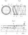
- FIG. 1 shows a cross section through a plastic pipe according to the invention, the wall of which is constructed in two layers with an inner layer 10 made of polyethylene, around which a helical conductor in the form of a flat copper strip 12 is wound.
- This helical conductor 12 is covered by a particularly hard outer layer 11 which forms a solid bond with the inner layer and is extruded onto the inner layer 10, for example.
- the outer layer consists for example of polypropylene, which optionally additionally has filler of a material of high hardness, for example of quartz, in order to increase the abrasion resistance of the outer layer.
- the material thickness of the outer layer 11 of the pipe wall may be less than that of the inner layer 10.
- FIG. 2 shows the corresponding side view or a longitudinal section of a plastic pipe according to the invention, wherein the end of the ends of the helically arranged flat copper strip, which serves as an electrical conductor serves to leak out so that, for example, it is possible to apply tension to these ends to check that the helical conductor is undamaged and thus the pipe is intact after installation.
- Fig. 3 shows a simplified schematic representation of a device according to the invention, by means of which one can check the proper installation of the pipeline.
- the illustration shows a drill head 13, which is driven and to which the pipe 14 is attached, so that it can be pulled through the soil during the trenchless laying.
- a measuring device 15 for example, a voltage to the ends emerging from the pipe 14 conductors 12a, 12b is applied and it is for example a simple resistance measurement made to determine whether the extending in the wall of the laid pipe electrical conductor 12 intact is.
Landscapes
- Engineering & Computer Science (AREA)
- Physics & Mathematics (AREA)
- Mining & Mineral Resources (AREA)
- Geology (AREA)
- Life Sciences & Earth Sciences (AREA)
- General Physics & Mathematics (AREA)
- General Life Sciences & Earth Sciences (AREA)
- Fluid Mechanics (AREA)
- Environmental & Geological Engineering (AREA)
- Mechanical Engineering (AREA)
- Geochemistry & Mineralogy (AREA)
- Acoustics & Sound (AREA)
- General Engineering & Computer Science (AREA)
- Rigid Pipes And Flexible Pipes (AREA)
- Lining Or Joining Of Plastics Or The Like (AREA)
- Investigating Or Analyzing Materials By The Use Of Electric Means (AREA)
Claims (13)
- Procédé de pose sans tranchée de tuyaux en matière plastique pour canalisations d'alimentation et d'évacuation, dans lequel le tuyau en matière plastique est rentré au moyen d'un dispositif motorisé sensiblement à l'horizontale dans la terre, par lequel on vérifie, après l'opération de pose, si la paroi de tuyau du tuyau en matière plastique a été endommagée sur l'extérieur par des objets se trouvant dans la terre,
caractérisé en ce qu'un tuyau en matière plastique comportant au moins une couche intérieure (10) de matière plastique et au moins une couche extérieure (11) de matière plastique ainsi qu'au moins un conducteur électrique (12) disposé en spirale entre la couche intérieure et la couche extérieure est rentré dans la terre, tandis que le conducteur électrique (12) constitue un circuit de courant électrique fermé et en ce qu'après l'opération de pose, on vérifie au moyen d'un dispositif de mesure (15) le flux de courant dans le conducteur et qu'on décide à partir de là si le tuyau en matière plastique a été posé sans endommagement. - Procédé selon la revendication 1, caractérisé en ce qu'après la pose, on mesure la canalisation et on détecte la position précise de la canalisation et/ou on détermine au moyen d'un dispositif de mesure l'emplacement d'une fuite détectée.
- Procédé selon la revendication 1 ou 2, caractérisé en ce qu'après la pose, on localise au moyen d'un dispositif de mesure un endommagement de la canalisation en matière plastique à l'aide d'un champ électromagnétique.
- Procédé selon l'une quelconque des revendications 1 à 3, caractérisé en ce qu'après la pose, on sollicite le conducteur disposé en spirale (12) au moyen d'une onde électromagnétique et qu'on localise le point de fuite à l'aide des interférences survenant alors.
- Procédé selon l'une quelconque des revendications 1 à 3, caractérisé en ce qu'après la pose de la canalisation, on localise un point de fuite par mesure d'un champ magnétique ou par mesure de résistance capacitive.
- Tuyau en matière plastique à utiliser dans un procédé de pose sans tranchée de canalisations d'alimentation et d'évacuation selon l'une quelconque des revendications 1 à 5, comportant au moins un conducteur électrique disposé en spirale (12) qui s'étend aussi près que possible de la paroi extérieure du tuyau en matière plastique, caractérisé en ce que le tuyau en matière plastique est réalisé sous forme d'un tuyau multicouche comprenant au moins une couche intérieure (10), au moins une couche extérieure (11) et au moins un conducteur électrique (12) s'étendant en spirale entre la couche intérieure (10) et la couche extérieure (11), tandis que l'au moins une couche extérieure (11) contient des corps de remplissage à haute résistance à l'usure, de préférence des corps de remplissage en quartz ou en verre.
- Tuyau en matière plastique selon la revendication 6, caractérisé en ce qu'on utilise comme conducteur électrique au moins un fil de cuivre.
- Tuyau en matière plastique selon la revendication 6, caractérisé en ce qu'il est prévu comme conducteur électrique au moins une bande de cuivre plate (12).
- Tuyau en matière plastique selon l'une quelconque des revendications 6 à 8, caractérisé en ce qu'il est prévu comme couche intérieure (10) au moins une couche de polyéthylène.
- Tuyau en matière plastique selon l'une quelconque des revendications 6 à 9, caractérisé en ce qu'il est prévu comme au moins une couche extérieure (11) une couche de polypropylène.
- Tuyau en matière plastique selon l'une quelconque des revendications 6 à 10, caractérisé en ce qu'il a un diamètre extérieur d'au moins 20 mm, de préférence situé entre environ 25 mm et environ 1 200 mm.
- Dispositif de contrôle d'une pose correcte de canalisations d'alimentation et d'évacuation posées sans tranchée, comprenant une canalisation posée dans la terre, qui comporte au moins un conducteur électrique (12) disposé suivant une extension en forme de spirale dans la paroi du tuyau ainsi qu'au moins un appareil de mesure pour vérifier un flux de courant dans le conducteur s'étendant en spirale (12) tout en appliquant une tension, caractérisé en ce que ce dispositif comprend au moins un tuyau en matière plastique selon l'une quelconque des revendications 6 à 11.
- Dispositif selon la revendication 12, caractérisé en ce qu'il comporte au moins un appareil de mesure pour localiser un endommagement de la canalisation en matière plastique, qui enregistre une interférence d'une onde électromagnétique avec laquelle le conducteur installé en spirale a été sollicité ou qui mesure une résistance capacitive ou qui mesure un champ magnétique lors d'une sollicitation du conducteur avec une tension alternative.
Priority Applications (1)
| Application Number | Priority Date | Filing Date | Title |
|---|---|---|---|
| PL05002689T PL1564366T3 (pl) | 2004-02-11 | 2005-02-09 | Sposób bezwykopowego układania rur z tworzywa sztucznego |
Applications Claiming Priority (4)
| Application Number | Priority Date | Filing Date | Title |
|---|---|---|---|
| DE202004002102U | 2004-02-11 | ||
| DE202004002102 | 2004-02-11 | ||
| DE202004002641U | 2004-02-20 | ||
| DE202004002641U DE202004002641U1 (de) | 2004-02-11 | 2004-02-20 | Prüfsystem für erdverlegte Kunststoffrohre |
Publications (2)
| Publication Number | Publication Date |
|---|---|
| EP1564366A1 EP1564366A1 (fr) | 2005-08-17 |
| EP1564366B1 true EP1564366B1 (fr) | 2006-08-30 |
Family
ID=34702145
Family Applications (1)
| Application Number | Title | Priority Date | Filing Date |
|---|---|---|---|
| EP05002689A Expired - Lifetime EP1564366B1 (fr) | 2004-02-11 | 2005-02-09 | Procédé de pose de tuyaux plastiques sans excavation |
Country Status (5)
| Country | Link |
|---|---|
| EP (1) | EP1564366B1 (fr) |
| AT (1) | ATE338194T1 (fr) |
| DE (1) | DE502005000073D1 (fr) |
| DK (1) | DK1564366T3 (fr) |
| PL (1) | PL1564366T3 (fr) |
Cited By (1)
| Publication number | Priority date | Publication date | Assignee | Title |
|---|---|---|---|---|
| DE102009037973A1 (de) * | 2009-08-20 | 2011-02-24 | Egeplast Werner Strumann Gmbh & Co. Kg | Verfahren zur Überwachung von Leckagen |
Families Citing this family (4)
| Publication number | Priority date | Publication date | Assignee | Title |
|---|---|---|---|---|
| DE102006033961B4 (de) * | 2006-07-22 | 2020-03-26 | Egeplast International Gmbh | Verfahren und Vorrichtung zur Ortung einer Beschädigung eines Kunststoffrohrs |
| US8183872B2 (en) * | 2008-07-09 | 2012-05-22 | Eaton Corporation | Hose with fault detection capability |
| DE102011000432A1 (de) | 2011-02-01 | 2012-08-02 | Egeplast Werner Strumann Gmbh & Co. Kg | Kunststoffrohr oder Kunststoffrohrbündel |
| DE102023103799A1 (de) | 2023-02-16 | 2024-08-22 | Egeplast International Gmbh | Kunststoffohr für den Medientransport unter lnnendruck mit integrierter Sensorik zur Funktionsüberwachung und Beschädigungsdetektion und Verfahren zur Installation eines derartigen Kunststoffrohrs |
Family Cites Families (7)
| Publication number | Priority date | Publication date | Assignee | Title |
|---|---|---|---|---|
| US3648282A (en) * | 1970-02-17 | 1972-03-07 | John B Kelly | Alarm signal apparatus to indicate damage to the insulation of an electrical cable as it is being laid underground |
| DE2304368A1 (de) * | 1973-01-26 | 1974-08-01 | Hansen Neuerburg Gmbh | Rohrleitung mit einer elektrischen sicherheitseinrichtung |
| US4336415A (en) * | 1980-05-16 | 1982-06-22 | Walling John B | Flexible production tubing |
| FR2691203A1 (fr) | 1992-05-15 | 1993-11-19 | Mr Ind | Tube auxiliaire sans raccord pour puits de forage profond. |
| WO1995031665A1 (fr) | 1994-05-12 | 1995-11-23 | Btr Plc | Tuyau dote d'un indicateur d'usure |
| US6004639A (en) * | 1997-10-10 | 1999-12-21 | Fiberspar Spoolable Products, Inc. | Composite spoolable tube with sensor |
| US6265880B1 (en) * | 1999-06-15 | 2001-07-24 | The United States Of America As Represented By The Secretary Of The Air Force | Apparatus and method for detecting conduit chafing |
-
2005
- 2005-02-09 EP EP05002689A patent/EP1564366B1/fr not_active Expired - Lifetime
- 2005-02-09 DE DE502005000073T patent/DE502005000073D1/de not_active Expired - Lifetime
- 2005-02-09 PL PL05002689T patent/PL1564366T3/pl unknown
- 2005-02-09 DK DK05002689T patent/DK1564366T3/da active
- 2005-02-09 AT AT05002689T patent/ATE338194T1/de active
Cited By (1)
| Publication number | Priority date | Publication date | Assignee | Title |
|---|---|---|---|---|
| DE102009037973A1 (de) * | 2009-08-20 | 2011-02-24 | Egeplast Werner Strumann Gmbh & Co. Kg | Verfahren zur Überwachung von Leckagen |
Also Published As
| Publication number | Publication date |
|---|---|
| DE502005000073D1 (de) | 2006-10-12 |
| EP1564366A1 (fr) | 2005-08-17 |
| ATE338194T1 (de) | 2006-09-15 |
| PL1564366T3 (pl) | 2007-01-31 |
| DK1564366T3 (da) | 2007-01-08 |
Similar Documents
| Publication | Publication Date | Title |
|---|---|---|
| AT404386B (de) | Doppelwandiger thermisch isolierter tubingstrang | |
| DE69434746T2 (de) | Verbesserte, mit Fett geschmierte Kabelanordnung zur Echtzeit-Oberflächenabbildung | |
| DE60105040T2 (de) | Verfahren zum verbinden von aneinanderstossenden expandierbaren rohren | |
| DE4314288C2 (de) | Verfahren und Vorrichtung zum Verlegen unterirdischer Rohrleitungen | |
| DE69517426T2 (de) | Verfahren zum auskleiden einer leitung mit einer auskleidung aus polymerem material | |
| EP2287587B1 (fr) | Procédé de surveillance de fuites dans des tubes plastiques utilisant des conducteurs électriques dans leur parois | |
| EP1564366A1 (fr) | Procédé de pose de tuyaux plastiques sans excavation | |
| DE102009011514A1 (de) | Kunststoffrohr mit strukturierter Außenschicht | |
| EP2481965B1 (fr) | Faisceau de tuyau en matière synthétique avec conducteur electrique | |
| DE3503391A1 (de) | Verfahren zur bau- und betriebskontrolle von fernwaermeleitungen sowie vorrichtung | |
| EP2025986B1 (fr) | Unité de tuyau comprenant au moins deux tuyaux | |
| DE29622414U1 (de) | Rohr aus thermoplastischem Kunststoff | |
| DE19645346C2 (de) | Verfahren zum Erneuern eines im Boden verlegten Schutzrohres für eine Produktenleitung | |
| DE933160C (de) | Elektrisches Kabel mit unter innerem oder aeusserem UEberdruck stehendem zweischichtigem Mantel | |
| EP2216577B1 (fr) | Pièce d'isolation tubulaire | |
| DE102007051956A1 (de) | Verfahren und Vorrichtung zur Überprüfung der Umhüllung einer Rohrleitung während der Verlegung in ein mit Flüssigkeit gefülltes Bohrloch | |
| EP0908598A2 (fr) | Procédé pour la pose d'une conduite et conduite comportant un tubage de revêtement et un tubage de production | |
| EP0648901B1 (fr) | Méthode et dispositif pour raccorder des bouches d'égout à un canal d'évacuation des eaux de pluie ou des eaux usées | |
| DE202005014630U1 (de) | Schutzmantel-Kunststoffrohr | |
| DE102018132949A1 (de) | Rohr aus Stahl mit einer Kunststoffummantelung als Schutzschicht gegen mechanische Beschädigungen, Herstellverfahren hierzu und Rohrleitung hieraus | |
| WO2008148514A2 (fr) | Procédé et dispositif de contrôle du gainage d'une tubulure lors de l'insertion dans un trou de forage rempli de liquide | |
| DE4028169A1 (de) | Verfahren zum sanieren von rohrleitungen | |
| DE4423921C1 (de) | Flexible Leitung zur Erdverlegung und Verfahren zur Herstellung | |
| WO2002077512A1 (fr) | Dispositif, procede et systeme de pose permettant d'assurer le soutien hydraulique d'un tunnel | |
| DE2435239A1 (de) | Verfahren zum pruefen einer pipeline |
Legal Events
| Date | Code | Title | Description |
|---|---|---|---|
| PUAI | Public reference made under article 153(3) epc to a published international application that has entered the european phase |
Free format text: ORIGINAL CODE: 0009012 |
|
| 17P | Request for examination filed |
Effective date: 20050519 |
|
| AK | Designated contracting states |
Kind code of ref document: A1 Designated state(s): AT BE BG CH CY CZ DE DK EE ES FI FR GB GR HU IE IS IT LI LT LU MC NL PL PT RO SE SI SK TR |
|
| AX | Request for extension of the european patent |
Extension state: AL BA HR LV MK YU |
|
| GRAP | Despatch of communication of intention to grant a patent |
Free format text: ORIGINAL CODE: EPIDOSNIGR1 |
|
| AKX | Designation fees paid |
Designated state(s): AT BE BG CH CY CZ DE DK EE ES FI FR GB GR HU IE IS IT LI LT LU MC NL PL PT RO SE SI SK TR |
|
| AXX | Extension fees paid |
Extension state: BA Payment date: 20060217 Extension state: LV Payment date: 20060217 Extension state: AL Payment date: 20060217 Extension state: YU Payment date: 20060217 Extension state: MK Payment date: 20060217 Extension state: HR Payment date: 20060217 |
|
| GRAS | Grant fee paid |
Free format text: ORIGINAL CODE: EPIDOSNIGR3 |
|
| GRAA | (expected) grant |
Free format text: ORIGINAL CODE: 0009210 |
|
| AK | Designated contracting states |
Kind code of ref document: B1 Designated state(s): AT BE BG CH CY CZ DE DK EE ES FI FR GB GR HU IE IS IT LI LT LU MC NL PL PT RO SE SI SK TR |
|
| AX | Request for extension of the european patent |
Extension state: AL BA HR LV MK YU |
|
| PG25 | Lapsed in a contracting state [announced via postgrant information from national office to epo] |
Ref country code: RO Free format text: LAPSE BECAUSE OF FAILURE TO SUBMIT A TRANSLATION OF THE DESCRIPTION OR TO PAY THE FEE WITHIN THE PRESCRIBED TIME-LIMIT Effective date: 20060830 Ref country code: LT Free format text: LAPSE BECAUSE OF FAILURE TO SUBMIT A TRANSLATION OF THE DESCRIPTION OR TO PAY THE FEE WITHIN THE PRESCRIBED TIME-LIMIT Effective date: 20060830 Ref country code: IT Free format text: LAPSE BECAUSE OF FAILURE TO SUBMIT A TRANSLATION OF THE DESCRIPTION OR TO PAY THE FEE WITHIN THE PRESCRIBED TIME-LIMIT;WARNING: LAPSES OF ITALIAN PATENTS WITH EFFECTIVE DATE BEFORE 2007 MAY HAVE OCCURRED AT ANY TIME BEFORE 2007. THE CORRECT EFFECTIVE DATE MAY BE DIFFERENT FROM THE ONE RECORDED. Effective date: 20060830 Ref country code: FI Free format text: LAPSE BECAUSE OF FAILURE TO SUBMIT A TRANSLATION OF THE DESCRIPTION OR TO PAY THE FEE WITHIN THE PRESCRIBED TIME-LIMIT Effective date: 20060830 Ref country code: SI Free format text: LAPSE BECAUSE OF FAILURE TO SUBMIT A TRANSLATION OF THE DESCRIPTION OR TO PAY THE FEE WITHIN THE PRESCRIBED TIME-LIMIT Effective date: 20060830 |
|
| REG | Reference to a national code |
Ref country code: GB Ref legal event code: FG4D Free format text: NOT ENGLISH |
|
| REG | Reference to a national code |
Ref country code: CH Ref legal event code: EP |
|
| REG | Reference to a national code |
Ref country code: IE Ref legal event code: FG4D Free format text: LANGUAGE OF EP DOCUMENT: GERMAN |
|
| REF | Corresponds to: |
Ref document number: 502005000073 Country of ref document: DE Date of ref document: 20061012 Kind code of ref document: P |
|
| PG25 | Lapsed in a contracting state [announced via postgrant information from national office to epo] |
Ref country code: BG Free format text: LAPSE BECAUSE OF FAILURE TO SUBMIT A TRANSLATION OF THE DESCRIPTION OR TO PAY THE FEE WITHIN THE PRESCRIBED TIME-LIMIT Effective date: 20061130 |
|
| PG25 | Lapsed in a contracting state [announced via postgrant information from national office to epo] |
Ref country code: ES Free format text: LAPSE BECAUSE OF FAILURE TO SUBMIT A TRANSLATION OF THE DESCRIPTION OR TO PAY THE FEE WITHIN THE PRESCRIBED TIME-LIMIT Effective date: 20061211 |
|
| REG | Reference to a national code |
Ref country code: SE Ref legal event code: TRGR |
|
| REG | Reference to a national code |
Ref country code: DK Ref legal event code: T3 |
|
| REG | Reference to a national code |
Ref country code: PL Ref legal event code: T3 |
|
| PG25 | Lapsed in a contracting state [announced via postgrant information from national office to epo] |
Ref country code: PT Free format text: LAPSE BECAUSE OF FAILURE TO SUBMIT A TRANSLATION OF THE DESCRIPTION OR TO PAY THE FEE WITHIN THE PRESCRIBED TIME-LIMIT Effective date: 20070206 |
|
| REG | Reference to a national code |
Ref country code: CH Ref legal event code: NV Representative=s name: PA ALDO ROEMPLER |
|
| PG25 | Lapsed in a contracting state [announced via postgrant information from national office to epo] |
Ref country code: MC Free format text: LAPSE BECAUSE OF NON-PAYMENT OF DUE FEES Effective date: 20070228 |
|
| ET | Fr: translation filed | ||
| REG | Reference to a national code |
Ref country code: HU Ref legal event code: AG4A Ref document number: E001236 Country of ref document: HU |
|
| PLBE | No opposition filed within time limit |
Free format text: ORIGINAL CODE: 0009261 |
|
| STAA | Information on the status of an ep patent application or granted ep patent |
Free format text: STATUS: NO OPPOSITION FILED WITHIN TIME LIMIT |
|
| 26N | No opposition filed |
Effective date: 20070531 |
|
| PG25 | Lapsed in a contracting state [announced via postgrant information from national office to epo] |
Ref country code: GR Free format text: LAPSE BECAUSE OF FAILURE TO SUBMIT A TRANSLATION OF THE DESCRIPTION OR TO PAY THE FEE WITHIN THE PRESCRIBED TIME-LIMIT Effective date: 20061201 |
|
| PG25 | Lapsed in a contracting state [announced via postgrant information from national office to epo] |
Ref country code: EE Free format text: LAPSE BECAUSE OF FAILURE TO SUBMIT A TRANSLATION OF THE DESCRIPTION OR TO PAY THE FEE WITHIN THE PRESCRIBED TIME-LIMIT Effective date: 20060830 |
|
| REG | Reference to a national code |
Ref country code: CH Ref legal event code: PCAR Free format text: ALDO ROEMPLER PATENTANWALT;BRENDENWEG 11 POSTFACH 154;9424 RHEINECK (CH) |
|
| PG25 | Lapsed in a contracting state [announced via postgrant information from national office to epo] |
Ref country code: IS Free format text: LAPSE BECAUSE OF NON-PAYMENT OF DUE FEES Effective date: 20070228 |
|
| PGRI | Patent reinstated in contracting state [announced from national office to epo] |
Ref country code: IT Effective date: 20090501 |
|
| PG25 | Lapsed in a contracting state [announced via postgrant information from national office to epo] |
Ref country code: CY Free format text: LAPSE BECAUSE OF FAILURE TO SUBMIT A TRANSLATION OF THE DESCRIPTION OR TO PAY THE FEE WITHIN THE PRESCRIBED TIME-LIMIT Effective date: 20060830 |
|
| PG25 | Lapsed in a contracting state [announced via postgrant information from national office to epo] |
Ref country code: TR Free format text: LAPSE BECAUSE OF FAILURE TO SUBMIT A TRANSLATION OF THE DESCRIPTION OR TO PAY THE FEE WITHIN THE PRESCRIBED TIME-LIMIT Effective date: 20060830 |
|
| PGFP | Annual fee paid to national office [announced via postgrant information from national office to epo] |
Ref country code: SK Payment date: 20110202 Year of fee payment: 7 |
|
| PGFP | Annual fee paid to national office [announced via postgrant information from national office to epo] |
Ref country code: IE Payment date: 20120217 Year of fee payment: 8 Ref country code: HU Payment date: 20120223 Year of fee payment: 8 |
|
| REG | Reference to a national code |
Ref country code: DE Ref legal event code: R082 Ref document number: 502005000073 Country of ref document: DE Representative=s name: FRITZ & BRANDENBURG PATENTANWAELTE, DE |
|
| REG | Reference to a national code |
Ref country code: DE Ref legal event code: R081 Ref document number: 502005000073 Country of ref document: DE Owner name: EGEPLAST INTERNATIONAL GMBH, DE Free format text: FORMER OWNER: EGEPLAST WERNER STRUMANN GMBH & CO. KG, 48268 GREVEN, DE Effective date: 20130628 Ref country code: DE Ref legal event code: R082 Ref document number: 502005000073 Country of ref document: DE Representative=s name: FRITZ & BRANDENBURG PATENTANWAELTE, DE Effective date: 20130628 Ref country code: DE Ref legal event code: R082 Ref document number: 502005000073 Country of ref document: DE Representative=s name: PATENTANWAELTE FRITZ & BRANDENBURG, DE Effective date: 20130628 |
|
| PG25 | Lapsed in a contracting state [announced via postgrant information from national office to epo] |
Ref country code: HU Free format text: LAPSE BECAUSE OF NON-PAYMENT OF DUE FEES Effective date: 20130210 Ref country code: SK Free format text: LAPSE BECAUSE OF NON-PAYMENT OF DUE FEES Effective date: 20130209 |
|
| REG | Reference to a national code |
Ref country code: SK Ref legal event code: MM4A Ref document number: E 1518 Country of ref document: SK Effective date: 20130209 |
|
| REG | Reference to a national code |
Ref country code: IE Ref legal event code: MM4A |
|
| PG25 | Lapsed in a contracting state [announced via postgrant information from national office to epo] |
Ref country code: IE Free format text: LAPSE BECAUSE OF NON-PAYMENT OF DUE FEES Effective date: 20130209 |
|
| REG | Reference to a national code |
Ref country code: FR Ref legal event code: PLFP Year of fee payment: 12 |
|
| REG | Reference to a national code |
Ref country code: FR Ref legal event code: PLFP Year of fee payment: 13 |
|
| REG | Reference to a national code |
Ref country code: FR Ref legal event code: PLFP Year of fee payment: 14 |
|
| REG | Reference to a national code |
Ref country code: DE Ref legal event code: R082 Ref document number: 502005000073 Country of ref document: DE Representative=s name: DUDA, RAFAEL THOMAS, DIPL.-ING. DR. RER. NAT., DE |
|
| P01 | Opt-out of the competence of the unified patent court (upc) registered |
Effective date: 20230914 |
|
| PGFP | Annual fee paid to national office [announced via postgrant information from national office to epo] |
Ref country code: LU Payment date: 20240228 Year of fee payment: 20 |
|
| PGFP | Annual fee paid to national office [announced via postgrant information from national office to epo] |
Ref country code: NL Payment date: 20240226 Year of fee payment: 20 |
|
| PGFP | Annual fee paid to national office [announced via postgrant information from national office to epo] |
Ref country code: AT Payment date: 20240227 Year of fee payment: 20 |
|
| PGFP | Annual fee paid to national office [announced via postgrant information from national office to epo] |
Ref country code: DE Payment date: 20240328 Year of fee payment: 20 Ref country code: CZ Payment date: 20240227 Year of fee payment: 20 Ref country code: CH Payment date: 20240307 Year of fee payment: 20 Ref country code: GB Payment date: 20240228 Year of fee payment: 20 |
|
| PGFP | Annual fee paid to national office [announced via postgrant information from national office to epo] |
Ref country code: SE Payment date: 20240226 Year of fee payment: 20 Ref country code: PL Payment date: 20240223 Year of fee payment: 20 Ref country code: IT Payment date: 20240226 Year of fee payment: 20 Ref country code: FR Payment date: 20240226 Year of fee payment: 20 Ref country code: DK Payment date: 20240226 Year of fee payment: 20 Ref country code: BE Payment date: 20240226 Year of fee payment: 20 |
|
| REG | Reference to a national code |
Ref country code: DE Ref legal event code: R071 Ref document number: 502005000073 Country of ref document: DE |
|
| REG | Reference to a national code |
Ref country code: DK Ref legal event code: EUP Expiry date: 20250209 |
|
| REG | Reference to a national code |
Ref country code: NL Ref legal event code: MK Effective date: 20250208 |
|
| REG | Reference to a national code |
Ref country code: CH Ref legal event code: PL |
|
| REG | Reference to a national code |
Ref country code: GB Ref legal event code: PE20 Expiry date: 20250208 |
|
| REG | Reference to a national code |
Ref country code: AT Ref legal event code: MK07 Ref document number: 338194 Country of ref document: AT Kind code of ref document: T Effective date: 20250209 |
|
| REG | Reference to a national code |
Ref country code: SE Ref legal event code: EUG |
|
| PG25 | Lapsed in a contracting state [announced via postgrant information from national office to epo] |
Ref country code: CZ Free format text: LAPSE BECAUSE OF EXPIRATION OF PROTECTION Effective date: 20250209 |
|
| PG25 | Lapsed in a contracting state [announced via postgrant information from national office to epo] |
Ref country code: GB Free format text: LAPSE BECAUSE OF EXPIRATION OF PROTECTION Effective date: 20250208 |
|
| REG | Reference to a national code |
Ref country code: BE Ref legal event code: MK Effective date: 20250209 |