EP1564360B1 - Device for the motorized opening and closing of a vehicle body element - Google Patents
Device for the motorized opening and closing of a vehicle body element Download PDFInfo
- Publication number
- EP1564360B1 EP1564360B1 EP05000208A EP05000208A EP1564360B1 EP 1564360 B1 EP1564360 B1 EP 1564360B1 EP 05000208 A EP05000208 A EP 05000208A EP 05000208 A EP05000208 A EP 05000208A EP 1564360 B1 EP1564360 B1 EP 1564360B1
- Authority
- EP
- European Patent Office
- Prior art keywords
- bowden cable
- slider
- guide cylinder
- guide
- piston
- Prior art date
- Legal status (The legal status is an assumption and is not a legal conclusion. Google has not performed a legal analysis and makes no representation as to the accuracy of the status listed.)
- Expired - Lifetime
Links
- 230000006835 compression Effects 0.000 claims description 5
- 238000007906 compression Methods 0.000 claims description 5
- 230000002441 reversible effect Effects 0.000 claims description 4
- 230000001747 exhibiting effect Effects 0.000 description 2
- 238000009434 installation Methods 0.000 description 2
- 238000011109 contamination Methods 0.000 description 1
- 238000001514 detection method Methods 0.000 description 1
Images


Classifications
-
- E—FIXED CONSTRUCTIONS
- E05—LOCKS; KEYS; WINDOW OR DOOR FITTINGS; SAFES
- E05F—DEVICES FOR MOVING WINGS INTO OPEN OR CLOSED POSITION; CHECKS FOR WINGS; WING FITTINGS NOT OTHERWISE PROVIDED FOR, CONCERNED WITH THE FUNCTIONING OF THE WING
- E05F15/00—Power-operated mechanisms for wings
- E05F15/60—Power-operated mechanisms for wings using electrical actuators
- E05F15/603—Power-operated mechanisms for wings using electrical actuators using rotary electromotors
- E05F15/611—Power-operated mechanisms for wings using electrical actuators using rotary electromotors for swinging wings
- E05F15/63—Power-operated mechanisms for wings using electrical actuators using rotary electromotors for swinging wings operated by swinging arms
-
- E—FIXED CONSTRUCTIONS
- E05—LOCKS; KEYS; WINDOW OR DOOR FITTINGS; SAFES
- E05F—DEVICES FOR MOVING WINGS INTO OPEN OR CLOSED POSITION; CHECKS FOR WINGS; WING FITTINGS NOT OTHERWISE PROVIDED FOR, CONCERNED WITH THE FUNCTIONING OF THE WING
- E05F15/00—Power-operated mechanisms for wings
- E05F15/60—Power-operated mechanisms for wings using electrical actuators
- E05F15/603—Power-operated mechanisms for wings using electrical actuators using rotary electromotors
- E05F15/611—Power-operated mechanisms for wings using electrical actuators using rotary electromotors for swinging wings
- E05F15/627—Power-operated mechanisms for wings using electrical actuators using rotary electromotors for swinging wings operated by flexible elongated pulling elements, e.g. belts, chains or cables
-
- E—FIXED CONSTRUCTIONS
- E05—LOCKS; KEYS; WINDOW OR DOOR FITTINGS; SAFES
- E05Y—INDEXING SCHEME ASSOCIATED WITH SUBCLASSES E05D AND E05F, RELATING TO CONSTRUCTION ELEMENTS, ELECTRIC CONTROL, POWER SUPPLY, POWER SIGNAL OR TRANSMISSION, USER INTERFACES, MOUNTING OR COUPLING, DETAILS, ACCESSORIES, AUXILIARY OPERATIONS NOT OTHERWISE PROVIDED FOR, APPLICATION THEREOF
- E05Y2900/00—Application of doors, windows, wings or fittings thereof
- E05Y2900/50—Application of doors, windows, wings or fittings thereof for vehicles
- E05Y2900/53—Type of wing
- E05Y2900/536—Hoods
-
- Y—GENERAL TAGGING OF NEW TECHNOLOGICAL DEVELOPMENTS; GENERAL TAGGING OF CROSS-SECTIONAL TECHNOLOGIES SPANNING OVER SEVERAL SECTIONS OF THE IPC; TECHNICAL SUBJECTS COVERED BY FORMER USPC CROSS-REFERENCE ART COLLECTIONS [XRACs] AND DIGESTS
- Y10—TECHNICAL SUBJECTS COVERED BY FORMER USPC
- Y10T—TECHNICAL SUBJECTS COVERED BY FORMER US CLASSIFICATION
- Y10T74/00—Machine element or mechanism
- Y10T74/18—Mechanical movements
- Y10T74/18568—Reciprocating or oscillating to or from alternating rotary
- Y10T74/18832—Reciprocating or oscillating to or from alternating rotary including flexible drive connector [e.g., belt, chain, strand, etc.]
-
- Y—GENERAL TAGGING OF NEW TECHNOLOGICAL DEVELOPMENTS; GENERAL TAGGING OF CROSS-SECTIONAL TECHNOLOGIES SPANNING OVER SEVERAL SECTIONS OF THE IPC; TECHNICAL SUBJECTS COVERED BY FORMER USPC CROSS-REFERENCE ART COLLECTIONS [XRACs] AND DIGESTS
- Y10—TECHNICAL SUBJECTS COVERED BY FORMER USPC
- Y10T—TECHNICAL SUBJECTS COVERED BY FORMER US CLASSIFICATION
- Y10T74/00—Machine element or mechanism
- Y10T74/20—Control lever and linkage systems
- Y10T74/20396—Hand operated
- Y10T74/20402—Flexible transmitter [e.g., Bowden cable]
- Y10T74/20462—Specific cable connector or guide
Definitions
- the invention relates to a device for motorized opening and closing of a pivotable about a flap body part of a motor vehicle, in particular a tailgate or a front hood, with a guide rail, in which a slider is slidably guided, which has an actuating rod, with its one end attached to the slider and hinged with its opposite end to the slider at a distance to the flap body on the pivotable body part, and with a drive by which the slider is reversibly slidably driven in the guideway, the drive a first Bowden cable and a second Bowden cable has, which are actuated by a drive device.
- the actuating rod is pivotally connected at one end to the slider.
- the two Bowden cables are secured with their one ends to the slider and extend oppositely through the track to be guided from the opposite ends of the track to the drive device. Depending on the direction of movement is the slider is acted upon by a soul pulling one of the Bowden cables.
- This device requires a large amount of space in a motor vehicle.
- a similar device having the features of the preamble of claim 1 is made FR-A-2730714 known.
- the object of the invention is therefore to provide a device of the type mentioned, which requires a small installation space with a simple structure.
- the guide rail hinged at one end in particular about a parallel to the flap axis pivot axis pivotally mounted on the body and the actuating rod with the slider is axially displaceable guided in the guideway and protrudes at the opposite end of the flap axis of the guideway wherein the first Bowden cable and the second Bowden cable are guided parallel to each other at the flap axis end of the guideway of the guideway to the drive device, and wherein the soul of the first Bowden cable with the guideway and the soul of the second Bowden cable firmly connected to the slider and the shell the first Bowden cable is supported on the slider and the sheath of the second Bowden cable is supported on the guide track.
- a plurality of guided in guideways operating rods and sliders can be driven by a single drive device slidably.
- the length of the device is small, so that only a small installation space is required.
- the device consists of a few, simply constructed components that can be mounted with little effort.
- the drive device comprises a reversibly rotatable drivable cable drum on which the souls of the first and the second Bowden cable each other up or are unwound.
- the two Bowden cables can each have a separate soul.
- the souls of the first and second Bowden cables form a closed loop so that they do not have separate fasteners at the cable drum need.
- the cable drum is preferably rotatably driven by an electric motor, wherein the cable drum can be driven by a reversible by reversing electric motor.
- the guide track is a guide cylinder and the slider is a displaceably guided in the guide cylinder piston having an actuating rod forming one-sided piston rod, which protrudes with its one end of the guide cylinder.
- the guide cylinder can be closed at its one end by a first closure wall, which has an axial extent to the extension of the guide bore, through which the actuating rod is slidably guided.
- the guide area of the guide cylinder is protected against contamination.
- the second closure wall may have an axial through-hole, through which the first Bowden cable is slidably guided.
- the actuating rod may be spring-loaded in the extension direction.
- a position detecting means For detecting the respective position of the pivotable body part can be detected by a position detecting means, the respective axial position of the actuating rod or the slider in the guideway.
- the position detection device is a submersible pulse sensor or a linear potentiometer.
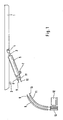
- tailgate 1 shows a tailgate 1 is shown, which is arranged pivotably about a flap axis 2 on the body of a motor vehicle.
- the free end 4 of a piston rod 3 is pivotally hinged to the tailgate 1.
- the piston rod 3 leads into a guide cylinder 5 and is there with its other end a slidably guided in the guide cylinder 5 piston 6 connected.
- the guide cylinder 5 is hinged at its free end 4 of the piston rod 3 opposite end about a parallel to the flap axis 2 pivot axis 7 pivotally mounted on the body of the motor vehicle.
- the souls 9 and 10 of the two Bowden cables 8 and 11 form a closed loop and wrap around the cable drum 13. Upon rotation of the cable drum 13, the one soul is wound by the same degree as the other soul is unwound, so that the two souls 9 and 10 then move in opposite directions.
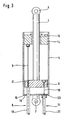
- the piston rod-side end of the guide cylinder 5 is closed by a first closure wall 14 and the opposite end of the guide cylinder 5 by a second closure wall 15.
- the second closure wall 15 is a bottom of a cup-shaped guide cylinder 5, while in the embodiment of Figure 2, the second closure wall 15 is a firmly inserted into the tubular guide cylinder 5 insert part.
- the first closure wall 14 is an insert part in all embodiments.
- the first closure wall 14 has an axial guide bore 16, through which the piston rod 3 is guided displaceably.
- One end of the core 9 of the first Bowden cable 8 is fixedly connected to the first closure wall 14.
- This core 9 extends axially through the guide cylinder 5, wherein it extends slidably through an axial opening 17 of the piston 6.
- the sheath 18 of the first Bowden cable 8 is displaceable by an axial through hole 19 in the second closure wall 15 passes into the guide cylinder 5 and is supported at one end axially on the piston 6 from.
- One end of the core 10 of the second Bowden cable 11 is fixedly connected to the piston 6.
- This core 10 extends axially through the guide cylinder 5 to the second closure wall 15 and is guided through a through-hole 20 in this second closure wall 15 to the outside.
- the end of the shell 21 of the second Bowden cable 11 is axially supported on the side facing away from the piston 6 of the second closure wall 15.
- the core 10 of the second Bowden cable 11 is thereby drawn with the piston 6 in the direction of the first closure wall 14 in the guide cylinder 5.
- This extension movement is supported in the embodiments of Figures 4 and 5 by a prestressed helical compression spring 22 which surrounds the guide cylinder 5 with play and is supported at one end to a support element 23 of the guide cylinder 5.
- the other end of the helical compression spring 22 is supported on a support element 24 on the protruding from the guide cylinder 5 end of the piston rod 3.
- a parallel to the piston rod 3 sensor rod 25 is attached to the support member 24, which extends through a sensor opening 26 in the first closure wall 14.
- the sensor rod 25 forms the movable part of a linear potentiometer whose stationary part is arranged in the sensor opening 26.
Landscapes
- Power-Operated Mechanisms For Wings (AREA)
Description
Die Erfindung bezieht sich auf eine Vorrichtung zum motorischen Öffnen und Schließen eines um eine Klappenachse schwenkbaren Karosserieteils eines Kraftfahrzeugs, insbesondere einer Heckklappe oder einer Fronthaube, mit einer Führungsbahn, in der ein Gleitstück verschiebbar geführt ist, das eine Betätigungsstange besitzt, die mit ihrem einen Ende an dem Gleitstück befestigt und mit ihrem dem Gleitstück entgegengesetzten Ende in einem Abstand zur Klappenachse an dem schwenkbaren Karosserieteil angelenkt ist, und mit einem Antrieb, durch den das Gleitstück in der Führungsbahn reversierbar verschiebbar antreibbar ist, wobei der Antrieb einen ersten Bowdenzug und einen zweiten Bowdenzug besitzt, die von einer Antriebsvorrichtung betätigbar sind.The invention relates to a device for motorized opening and closing of a pivotable about a flap body part of a motor vehicle, in particular a tailgate or a front hood, with a guide rail, in which a slider is slidably guided, which has an actuating rod, with its one end attached to the slider and hinged with its opposite end to the slider at a distance to the flap body on the pivotable body part, and with a drive by which the slider is reversibly slidably driven in the guideway, the drive a first Bowden cable and a second Bowden cable has, which are actuated by a drive device.
Bei einer derartigen bekannten Vorrichtung ist die Betätigungsstange mit einem Ende schwenkbar an dem Gleitstück angelenkt. Die beiden Bowdenzüge sind mit ihren einen Enden an dem Gleitstück befestigt und erstrecken sich einander entgegengesetzt durch die Führungsbahn, um von den einander entgegengesetzten Enden der Führungsbahn aus zur Antriebsvorrichtung geführt zu werden. Je nach Bewegungsrichtung wird das Gleitstück von einer Seele eines der Bowdenzüge ziehend beaufschlagt.In such a known device, the actuating rod is pivotally connected at one end to the slider. The two Bowden cables are secured with their one ends to the slider and extend oppositely through the track to be guided from the opposite ends of the track to the drive device. Depending on the direction of movement is the slider is acted upon by a soul pulling one of the Bowden cables.
Diese Vorrichtung benötigt einen großen Bauraum in einem Kraftfahrzeug.This device requires a large amount of space in a motor vehicle.
Eine ähnliche Vorrichtung, die die Merkmale des Oberbegriffs des Anspruchs 1 aufweist, ist aus
Aufgabe der Erfindung ist es daher eine Vorrichtung der eingangs genannten Art zu schaffen, die bei einfachem Aufbau einen geringen Einbauraum erfordert.The object of the invention is therefore to provide a device of the type mentioned, which requires a small installation space with a simple structure.
Diese Aufgabe wird erfindungsgemäß dadurch gelöst, daß die Führungsbahn mit ihrem einen Ende insbesondere um eine zur Klappenachse parallele Schwenkachse schwenkbar an der Karosserie angelenkt und die Betätigungsstange mit dem Gleitstück axial verschiebbar in der Führungsbahn geführt ist und an dem der Klappenachse entgegengesetzten Ende aus der Führungsbahn herausragt, wobei der erste Bowdenzug und der zweite Bowdenzug parallel zueinander an dem klappenachsenseitigen Ende der Führungsbahn von der Führungsbahn weg zur Antriebsvorrichtung geführt sind, und wobei die Seele des ersten Bowdenzugs mit der Führungsbahn und die Seele des zweiten Bowdenzugs mit dem Gleitstück fest verbunden sowie die Hülle des ersten Bowdenzugs an dem Gleitstück und die Hülle des zweiten Bowdenzugs an der Führungsbahn abgestützt ist.This object is achieved in that the guide rail hinged at one end in particular about a parallel to the flap axis pivot axis pivotally mounted on the body and the actuating rod with the slider is axially displaceable guided in the guideway and protrudes at the opposite end of the flap axis of the guideway wherein the first Bowden cable and the second Bowden cable are guided parallel to each other at the flap axis end of the guideway of the guideway to the drive device, and wherein the soul of the first Bowden cable with the guideway and the soul of the second Bowden cable firmly connected to the slider and the shell the first Bowden cable is supported on the slider and the sheath of the second Bowden cable is supported on the guide track.
Es versteht sich, daß durch eine einzige Antriebsvorrichtung auch mehrere in Führungsbahnen geführte Betätigungsstangen und Gleitstücke verschiebbar antreibbar sein können.It is understood that a plurality of guided in guideways operating rods and sliders can be driven by a single drive device slidably.
Dadurch, daß beide Bowdenzüge von dem gleichen Ende der Führungsbahn aus zur Antriebsvorrichtung geführt werden, ist die Länge der Vorrichtung gering, so daß nur ein kleiner Einbauraum erforderlich ist. Dabei besteht die Vorrichtung aus wenigen, einfach aufgebauten Bauteilen, die auch mit nur geringem Aufwand montierbar sind.The fact that both Bowden cables are guided from the same end of the guideway to the drive device, the length of the device is small, so that only a small installation space is required. In this case, the device consists of a few, simply constructed components that can be mounted with little effort.
Ebenfalls zu einer geringen Baugröße trägt es bei, daß die Antriebsvorrichtung eine reversierbar drehbar antreibbare Seiltrommel aufweist, auf die die Seelen des ersten und des zweiten Bowdenzugs einander gegenläufig auf- bzw. abwickelbar sind.Also contributing to a small size, it helps that the drive device comprises a reversibly rotatable drivable cable drum on which the souls of the first and the second Bowden cable each other up or are unwound.
Damit wird die Seele des einen Bowdenzugs immer im gleichen Maß aufgewickelt wie die Seele des anderen Bowdenzugs abgewickelt wird.Thus, the soul of a Bowden cable is always wound to the same extent as the soul of the other Bowden cable is wound.
Die beiden Bowdenzüge können jeweils eine separate Seele besitzen.The two Bowden cables can each have a separate soul.
Vorzugsweise bilden aber die Seelen des ersten und des zweiten Bowdenzugs eine geschlossene Schleife, so daß sie keine separaten Befestigungselemente an der Seiltrommel benötigen. Die Seiltrommel ist vorzugsweise elektromotorisch drehbar antreibbar, wobei die Seiltrommel von einem durch Umpolung drehrichtungsumkehrbaren Elektromotor antreibbar sein kann.Preferably, however, the souls of the first and second Bowden cables form a closed loop so that they do not have separate fasteners at the cable drum need. The cable drum is preferably rotatably driven by an electric motor, wherein the cable drum can be driven by a reversible by reversing electric motor.
Ein Aufbau mit einfachen und damit kostengünstigen Bauteilen wird damit erreicht, daß die Führungsbahn ein Führungszylinder und das Gleitstück ein in dem Führungszylinder verschiebbar geführter Kolben ist, der eine die Betätigungsstange bildende einseitige Kolbenstange aufweist, die mit ihrem einen Ende aus dem Führungszylinder herausragt.A structure with simple and therefore inexpensive components is achieved in that the guide track is a guide cylinder and the slider is a displaceably guided in the guide cylinder piston having an actuating rod forming one-sided piston rod, which protrudes with its one end of the guide cylinder.
Zur einfachen Führung der Betätigungsstange kann der Führungszylinder an seinem einen Ende durch eine erste Verschlußwand verschlossen sein, die eine zur Erstreckung des Führungszylinders axiale Führungsbohrung aufweist, durch die die Betätigungsstange verschiebbar hindurchgeführt ist.For easy guidance of the actuating rod, the guide cylinder can be closed at its one end by a first closure wall, which has an axial extent to the extension of the guide bore, through which the actuating rod is slidably guided.
Dabei wird gleichzeitig der Führungsbereich des Führungszylinders gegen Verschmutzen geschützt.At the same time, the guide area of the guide cylinder is protected against contamination.
Dies insbesondere auch dann, wenn der Führungszylinder an seinem anderen Ende durch eine zweite Verschlußwand verschlossen ist.This is especially true when the guide cylinder is closed at its other end by a second closure wall.
Zu einem Schutz der Seele des ersten Bowdenzugs führt es, wenn das eine Ende der Seele des ersten Bowdenzugs mit der ersten Verschlußwand verbunden ist und der erste Bowdenzug sich axial durch den Führungszylinder erstreckt, wobei die Seele des ersten Bowdenzugs sich verschiebbar durch eine Axialöffnung des Kolbens erstreckt und das eine Ende der Hülle des ersten Bowdenzugs auf der der ersten Verschlußwand entgegengesetzten Seite des Kolbens axial abgestützt ist.To a protection of the soul of the first Bowden cable leads, when the one end of the soul of the first Bowden cable is connected to the first closure wall and the first Bowden cable extends axially through the guide cylinder, the soul of the first Bowden cable slidably through an axial opening of the piston extends and one end of the sheath of the first Bowden cable is axially supported on the first closure wall opposite side of the piston.
Dabei kann die zweite Verschlußwand eine axiale Durchführbohrung aufweisen, durch die der erste Bowdenzug verschiebbar hindurchgeführt ist.In this case, the second closure wall may have an axial through-hole, through which the first Bowden cable is slidably guided.
Ebenfalls zum Schutz der Seele des zweiten Bowdenzugs führt es, wenn das eine Ende der Seele des zweiten Bowdenzugs mit dem Kolben verbunden ist und der zweite Bowdenzug sich axial durch den Führungszylinder erstreckt, wobei die Seele des zweiten Bowdenzugs sich verschiebbar durch eine Durchführbohrung der zweiten Verschlußwand erstreckt und das eine Ende der Hülle des zweiten Bowdenzugs auf der dem Kolben abgewandten Seite der zweiten Verschlußwand axial abgestützt ist.It also leads to the protection of the soul of the second Bowden cable, when one end of the soul of the second Bowden cable is connected to the piston and the second Bowden cable extends axially through the guide cylinder, the soul of the second Bowden cable slidably through a through-hole of the second closure wall extends and one end of the sheath of the second Bowden cable is axially supported on the side facing away from the piston of the second closure wall.
Zur Unterstützung einer Ausfahrbewegung, die die Öffnungsbewegung des schwenkbaren Karosserieteils sein kann, kann die Betätigungsstange in Ausfahrrichtung federbeaufschlagt sein.To support an extension movement, which may be the opening movement of the pivotable body part, the actuating rod may be spring-loaded in the extension direction.
Dazu kann in einfach aufgebauter und platzsparender Weise der Führungszylinder mit Spiel von einer Schraubendruckfeder umschlossen sein, die mit ihrem einen Ende an einem Abstützelement des Führungszylinders und mit ihrem anderen Ende an einem Abstützelement des aus dem Führungszylinder herausragenden Endes der Betätigungsstange abgestützt ist.These can be enclosed in a simple design and space-saving manner of the guide cylinder with clearance of a helical compression spring which is supported with its one end to a support member of the guide cylinder and with its other end to a support member of the projecting from the guide cylinder end of the actuating rod.
Zum Erfassen der jeweiligen Position des schwenkbaren Karosserieteils kann durch eine Positionserfassungseinrichtung die jeweilige axiale Position der Betätigungsstange oder des Gleitstücks in der Führungsbahn erfaßbar sein.For detecting the respective position of the pivotable body part can be detected by a position detecting means, the respective axial position of the actuating rod or the slider in the guideway.
Dabei ist in einfacher Ausbildung die Positionserfassungseinrichtung ein Tauchspulsensor oder ein Linearpotentiometer.In this case, in a simple embodiment, the position detection device is a submersible pulse sensor or a linear potentiometer.
Ausführungsbeispiele der Erfindung sind in der Zeichnung dargestellt und werden im folgenden näher beschrieben. Es zeigen
Figur 1- eine Heckklappe eines Kraftfahrzeugs mit einer Seitenansicht einer Vorrichtung zum motorischen Öffnen und Schließen der Heckklappe
Figur 2- die Vorrichtung zum motorischen Öffnen und Schließen nach
Figur 1 im Schnitt Figur 3- ein zweites Ausführungsbeispiel einer Vorrichtung zum motorischen Öffnen und Schließen einer Heckklappe im Schnitt
- Figur 4
- ein drittes Ausführungsbeispiel einer Vorrichtung zum motorischen Öffnen und Schließen einer Heckklappe im Schnitt
Figur 5- ein viertes Ausführungsbeispiel einer Vorrichtung zum motorischen Öffnen und Schließen einer Heckklappe im Schnitt.
- FIG. 1
- a tailgate of a motor vehicle with a side view of a device for the motorized opening and closing of the tailgate
- FIG. 2
- the device for motorized opening and closing of Figure 1 in section
- FIG. 3
- A second embodiment of a device for motorized opening and closing a tailgate in section
- FIG. 4
- a third embodiment of a device for motorized opening and closing a tailgate in section
- FIG. 5
- A fourth embodiment of a device for motorized opening and closing a tailgate in section.
In Figur 1 ist eine Heckklappe 1 dargestellt, die um eine Klappenachse 2 schwenkbar an der Karosserie eines Kraftfahrzeugs angeordnet ist.1 shows a
In einem Abstand zur Klappenachse 2 ist das freie Ende 4 einer Kolbenstange 3 schwenkbar an der Heckklappe 1 angelenkt. Die Kolbenstange 3 führt in einen Führungszylinder 5 und ist dort mit ihrem anderen Ende mit einem in dem Führungszylinder 5 verschiebbar geführten Kolben 6 verbunden.At a distance from the
Der Führungszylinder 5 ist an seinem dem freien Ende 4 der Kolbenstange 3 entgegengesetzten Ende um eine zur Klappenachse 2 parallele Schwenkachse 7 schwenkbar an der Karosserie des Kraftfahrzeugs angelenkt.The
Aus dem der Kolbenstange 3 entgegengesetzten Ende des Führungszylinders 5 ist ein eine Seele 9 aufweisender erster Bowdenzug 8 und ein ebenfalls eine Seele 10 aufweisender zweiter Bowdenzug 11 herausgeführt. Diese beiden Bowdenzüge 8 und 11 führen zu einer Antriebsvorrichtung mit einer durch einen drehrichtungsumkehrbaren Elektromotor 12 drehbar antreibbaren Seiltrommel 13.From the
Die Seelen 9 und 10 der beiden Bowdenzüge 8 und 11 bilden eine geschlossene Schleife und umschlingen die Seiltrommel 13. Bei Drehung der Seiltrommel 13 wird die eine Seele um das gleiche Maß aufgewickelt, wie die andere Seele abgewickelt wird, so daß die beiden Seelen 9 und 10 sich dann gegenläufig bewegen.The
Wie die Figuren 2 bis 5 zeigen ist das kolbenstangenseitige Ende des Führungszylinders 5 durch eine erste Verschlußwand 14 und das entgegengesetzte Ende des Führungszylinders 5 durch eine zweite Verschlußwand 15 verschlossen.
Bei den Ausführungsbeispielen der Figuren 3 bis 5 ist die zweite Verschlußwand 15 ein Boden eines topfartig ausgebildeten Führungszylinders 5, während bei dem Ausführungsbeispiel der Figur 2 die zweite Verschlußwand 15 ein in den rohrförmigen Führungszylinder 5 fest eingesetztes Einsatzteil ist.As shown in FIGS. 2 to 5, the piston rod-side end of the
In the embodiments of Figures 3 to 5, the
Die erste Verschlußwand 14 ist bei allen Ausführungsbeispielen ein Einsatzteil.The
Die erste Verschlußwand 14 weist eine axiale Führungsbohrung 16 auf, durch die die Kolbenstange 3 verschiebbar hindurchgeführt ist.The
Das eine Ende der Seele 9 des ersten Bowdenzugs 8 ist fest mit der ersten Verschlußwand 14 verbunden. Diese Seele 9 erstreckt sich axial durch den Führungszylinder 5, wobei sie sich verschiebbar durch eine Axialöffnung 17 des Kolbens 6 erstreckt. Die Hülle 18 der ersten Bowdenzugs 8 ist verschiebbar durch eine axiale Durchführbohrung 19 in der zweiten Verschlußwand 15 hindurch in den Führungszylinder 5 hineingeführt und stützt sich mit ihrem einen Ende axial an dem Kolben 6 ab.One end of the
Das eine Ende der Seele 10 des zweiten Bowdenzugs 11 ist fest mit dem Kolben 6 verbunden. Diese Seele 10 erstreckt sich axial durch den Führungszylinder 5 zur zweiten Verschlußwand 15 hin und ist durch eine Durchführbohrung 20 in dieser zweiten Verschlußwand 15 nach außen geführt.One end of the
Das Ende der Hülle 21 des zweiten Bowdenzugs 11 ist auf der dem Kolben 6 abgewandten Seite der zweiten Verschlußwand 15 axial abgestützt.The end of the
Bei einer Zugbeaufschlagung der Seele 10 des zweiten Bowdenzugs 11 zieht diese Seele 11 den Kolben 6 in Einfahrrichtung der Kolbenstange 3, so daß die Heckklappe 1 in Schließrichtung geschwenkt wird. Dabei wird auch die Hülle 18 des ersten Bowdenzugs 8 in Einfahrrichtung verschoben, während die Seele 9 feststehend verbleibt.When a train of the
Erfolgt eine Zugbeanspruchung der Seele 9 des ersten Bowdenzugs 8, wird die Hülle 18 des ersten Bowdenzugs 8 zur ersten Verschlußwand 14 hin bewegt, so daß sie in dieser Richtung auch den Kolben 6 beaufschlagt. Damit bewegt sich dieser und somit auch die Kolbenstange 3 in Ausfahrrichtung und beaufschlagt die Heckklappe 1 in Öffnungsrichtung.If a tensile stress of the
Die Seele 10 des zweiten Bowdenzugs 11 wird dabei mit dem Kolben 6 in Richtung zur ersten Verschlußwand 14 in den Führungszylinder 5 hineingezogen.
Diese Ausfahrbewegung wird bei den Ausführungsbeispielen der Figuren 4 und 5 durch eine vorgespannte Schraubendruckfeder 22 unterstützt, die mit Spiel den Führungszylinder 5 umschließt und mit ihrem einen Ende an einem Abstützelement 23 des Führungszylinders 5 abgestützt ist. Das andere Ende der Schraubendruckfeder 22 ist an einem Abstützelement 24 an dem aus dem Führungszylinder 5 herausragenden Ende der Kolbenstange 3 abgestützt.The
This extension movement is supported in the embodiments of Figures 4 and 5 by a prestressed
Bei dem Ausführungsbeispiel der Figur 5 ist an dem Abstützelement 24 noch eine zur Kolbenstange 3 parallele Sensorstange 25 befestigt, die eine Sensoröffnung 26 in der ersten Verschlußwand 14 durchragt. Dabei bildet die Sensorstange 25 den beweglichen Teil eines Linearpotentiometers, dessen stationärer Teil in der Sensoröffnung 26 angeordnet ist.In the embodiment of Figure 5, a parallel to the
- 11
- Heckklappetailgate
- 22
- Klappenachsedamper shaft
- 33
- Kolbenstangepiston rod
- 44
- freies Endefree end
- 55
- Führungszylinderguide cylinder
- 66
- Kolbenpiston
- 77
- Schwenkachseswivel axis
- 88th
- erster Bowdenzugfirst Bowden cable
- 99
- Seelesoul
- 1010
- Seelesoul
- 1111
- zweiter Bowdenzugsecond Bowden cable
- 1212
- Elektromotorelectric motor
- 1313
- Seiltrommelcable drum
- 1414
- erste Verschlußwandfirst closure wall
- 1515
- zweite Verschlußwandsecond shutter wall
- 1616
- Führungsbohrungguide bore
- 1717
- Axialöffnungaxial opening
- 1818
- Hülleshell
- 1919
- DurchführbohrungThrough-hole
- 2020
- DurchführbohrungThrough-hole
- 2121
- Hülleshell
- 2222
- SchraubendruckfederHelical compression spring
- 2323
- Abstützelementsupporting
- 2424
- Abstützelementsupporting
- 2525
- Sensorstangesensor rod
- 2626
- Sensoröffnungsensor opening
Claims (15)
- Device for the motorized opening and closing of a motor vehicle body part which can be pivoted about a hinged-lid axis, in particular a tailgate or a front lid, having a guide track in which a slider is displaceably guided, the slider having an actuating rod which is fastened at its one end to the slider and at its end opposite the slider is coupled to the pivotable body part at a distance from the hinged-lid axis, and having a drive by means of which the slider can be driven in a reversible and displaceable manner in the guide track, the drive having a first Bowden cable and a second Bowden cable which can be actuated by a drive device, the guide track being coupled at its one end to the body, in particular in a manner such that it can be pivoted about a pivot axis (7) parallel to the hinged-lid axis (2), and the actuating rod together with the slider being guided in the guide track in an axially displaceable manner and at the end opposite the hinged-lid axis (2) protruding out of the guide track, characterized in that the first Bowden cable (8) and the second Bowden cable (11), at that end of the guide track which is on the hinged-lid-axis side, are guided parallel to each other away from the guide track to the drive device, and in that the core (9) of the first Bowden cable (8) is connected fixedly to the guide track and the core (10) of the second Bowden cable (11) is connected fixedly to the slider, and the sheath (18) of the first Bowden cable (8) is supported on the slider and the sheath (21) of the second Bowden cable (11) is supported on the guide track.
- Device according to Claim 1, characterized in that the drive device has a cable drum (13) which can be driven in a reversible and rotatable manner and onto which the cores (9, 10) of the first and of the second Bowden cable (8, 11) can be wound and unwound in a mutually opposed manner.
- Device according to Claim 1, characterized in that the cores (9, 10) of the first and of the second Bowden cable (8, 11) form a closed loop.
- Device according to either of Claims 2 and 3, characterized in that the cable drum (13) can be driven in a rotatable manner by means of an electric motor.
- Device according to Claim 4, characterized in that the cable drum (13) can be driven by an electric motor (12) which can be reversed in direction of rotation by means of pole reversal.
- Device according to one of the preceding claims, characterized in that the guide track is a guide cylinder (5) and the slider is a piston (6) which is guided displaceably in the guide cylinder (5) and has a piston rod (3) on one side forming the actuating rod and protruding at its one end out of the guide cylinder (5).
- Device according to Claim 6, characterized in that the guide cylinder (5) is closed at its one end by a first closing wall (14) which has a guide hole (16) which is axial with respect to the extent of the guide cylinder (5) and through which the actuating rod is displaceably guided.
- Device according to either of Claims 6 and 7, characterized in that the guide cylinder (5) is closed at its other end by a second closing wall (15).
- Device according to either of Claims 7 and 8, characterized in that one end of the core (9) of the first Bowden cable (8) is connected to the first closing wall (14) and the first Bowden cable (8) extends axially through the guide cylinder (5), the core (9) of the first Bowden cable (8) extending displaceably through an axial opening (17) of the piston (6), and one end of the sheath (18) of the first Bowden cable (8) being supported axially on that side of the piston (6) which is opposite the first closing wall (14).
- Device according to one of Claims 7 to 9, characterized in that the second closing wall (15) has an axial guide-through hole (19) through which the first Bowden cable (18) is displaceably guided.
- Device according to one of Claims 6 to 10, characterized in that one end of the core (10) of the second Bowden cable (11) is connected to the piston (6) and the second Bowden cable (11) extends axially through the guide cylinder (5), the core (10) of the second Bowden cable (11) extending displaceably through a guide-through hole (20) of the second closing wall (15) and one end of the sheath (21) of the second Bowden cable (11) being supported axially on that side of the closing second wall (15) which faces away from the piston (6).
- Device according to one of the preceding claims, characterized in that the actuating rod is springloaded in the extension direction.
- Device according to Claim 12, characterized in that the guide cylinder (5) is enclosed with play by a helical compression spring (22) which is supported at its one end on a supporting element (23) of the guide cylinder (5) and at its other end on a supporting element (24) of that end of the actuating rod which protrudes out of the guide cylinder (5).
- Device according to one of the preceding claims, characterized in that the particular axial position of the actuating rod or of the slider in the guide track can be detected by means of a position-detecting device.
- Device according to Claim 14, characterized in that the position-detecting device is a moving coil sensor or a linear potentiometer.
Applications Claiming Priority (2)
| Application Number | Priority Date | Filing Date | Title |
|---|---|---|---|
| DE102004007126A DE102004007126A1 (en) | 2004-02-12 | 2004-02-12 | Device for the motorized opening and closing of a body part |
| DE102004007126 | 2004-02-12 |
Publications (2)
| Publication Number | Publication Date |
|---|---|
| EP1564360A1 EP1564360A1 (en) | 2005-08-17 |
| EP1564360B1 true EP1564360B1 (en) | 2007-07-04 |
Family
ID=34684042
Family Applications (1)
| Application Number | Title | Priority Date | Filing Date |
|---|---|---|---|
| EP05000208A Expired - Lifetime EP1564360B1 (en) | 2004-02-12 | 2005-01-07 | Device for the motorized opening and closing of a vehicle body element |
Country Status (3)
| Country | Link |
|---|---|
| US (1) | US7506556B2 (en) |
| EP (1) | EP1564360B1 (en) |
| DE (2) | DE102004007126A1 (en) |
Families Citing this family (9)
| Publication number | Priority date | Publication date | Assignee | Title |
|---|---|---|---|---|
| DE102005030054B4 (en) * | 2005-06-27 | 2009-04-02 | Stabilus Gmbh | opening device |
| DE202005021669U1 (en) * | 2005-07-08 | 2009-03-12 | Stabilus Gmbh | Device for motor- and power-operated moving a pivotable about a pivot axis flap of a vehicle |
| US7926863B2 (en) * | 2007-07-31 | 2011-04-19 | Dura Global Technologies, Llc | Power hinge mechanism using a push-pull cable |
| DE102007053452A1 (en) * | 2007-11-07 | 2009-05-14 | Stabilus Gmbh | driving means |
| DE102008009898B4 (en) * | 2007-11-13 | 2010-07-15 | Stabilus Gmbh | Flap opening and closing system |
| TWM412127U (en) * | 2011-01-31 | 2011-09-21 | Ren-Fa Luo | Improved front and rear wheel brake control device |
| AT512156B1 (en) * | 2012-05-25 | 2013-06-15 | Blum Gmbh Julius | Arrangement for moving a movable furniture part |
| JP6768401B2 (en) * | 2016-08-05 | 2020-10-14 | 株式会社ユーシン | Vehicle door switchgear |
| DE102016118388A1 (en) * | 2016-09-28 | 2018-03-29 | Brose Fahrzeugteile Gmbh & Co. Kommanditgesellschaft, Bamberg | drive kinematics |
Family Cites Families (22)
| Publication number | Priority date | Publication date | Assignee | Title |
|---|---|---|---|---|
| US2914955A (en) * | 1957-11-12 | 1959-12-01 | Univ Kingston | Synchronizing mechanism for free piston engines |
| JPS5917621A (en) * | 1982-07-20 | 1984-01-28 | Nissan Motor Co Ltd | Device for taking out transmission force of push-pull cable |
| DE3329543A1 (en) * | 1983-08-16 | 1985-02-28 | Geze Gmbh, 7250 Leonberg | DEVICE FOR REGULATING THE CLOSING ORDER OF DOUBLE DOORS |
| US4702117A (en) * | 1986-03-31 | 1987-10-27 | Kokusan Kinzoku Kogyo Kabushiki Kaisha | Lock actuator for a pair of locks |
| US4900187A (en) * | 1987-10-23 | 1990-02-13 | Nyman Pile Driving, Inc. | Hydraulic actuator and lift apparatus |
| DE3744083A1 (en) * | 1987-12-24 | 1989-07-06 | Opel Adam Ag | DEVICE FOR OPENING AND CLOSING SWIVELING BODY PARTS OF MOTOR VEHICLES |
| US4851742A (en) | 1989-01-26 | 1989-07-25 | General Motors Corporation | Compartment panel control apparatus for a motor vehicle |
| US4936424A (en) * | 1989-05-09 | 1990-06-26 | Costa Vince F | Hydraulic shock absorber with pressure sensitive external valving |
| DE4124869A1 (en) | 1991-07-26 | 1993-01-28 | Bayerische Motoren Werke Ag | Motorised drive esp. for tailgate of motor vehicle - is geared to spring-balanced gate with overload safety coupling and compact piston in cylinder guide |
| DE4224132C2 (en) * | 1992-07-22 | 2002-11-14 | Stabilus Gmbh | Door locking system |
| JPH0680024A (en) * | 1992-09-01 | 1994-03-22 | Nippondenso Co Ltd | Automatic opening and closing device for vehicle door |
| DE19504301C2 (en) * | 1994-02-10 | 1997-07-24 | Honda Motor Co Ltd | System for selective actuation of two driven elements by a single actuating element |
| FR2717215B1 (en) * | 1994-03-08 | 1996-04-19 | Renault | Motorized control device for opening and closing a tailgate of a motor vehicle. |
| FR2730714B1 (en) * | 1995-02-16 | 1997-03-21 | Renault | MOTORIZED CYLINDER, IN PARTICULAR FOR A DEVICE FOR CONTROLLING THE OPENING AND CLOSING OF A MOTOR VEHICLE TAILGATE |
| US5588258A (en) * | 1995-03-01 | 1996-12-31 | General Motors Corporation | Power operator for pivotable vehicle closure element |
| JP3850480B2 (en) * | 1996-01-29 | 2006-11-29 | 中央発條株式会社 | Remote control device using cable |
| DE19636272A1 (en) * | 1996-09-06 | 1998-03-12 | Star Gmbh | Linear guide device |
| ES2198183B1 (en) * | 2000-03-27 | 2005-04-01 | Stabilus Gmbh | OPERATING SYSTEM INCLUDING A PISTON-CYLINDER GROUP COMBINED WITH A DRIVING DEVICE. |
| US6516567B1 (en) * | 2001-01-19 | 2003-02-11 | Hi-Lex Corporation | Power actuator for lifting a vehicle lift gate |
| DE10119340A1 (en) * | 2001-04-20 | 2002-10-31 | Stabilus Gmbh | Actuating system for a flap or the like |
| US6883275B2 (en) * | 2002-07-29 | 2005-04-26 | Multimatic, Inc. | Method and apparatus for controlling the speed of closing of a movable element |
| DE10245458A1 (en) * | 2002-09-28 | 2004-04-08 | Stabilus Gmbh | actuator |
-
2004
- 2004-02-12 DE DE102004007126A patent/DE102004007126A1/en not_active Withdrawn
-
2005
- 2005-01-07 DE DE502005000952T patent/DE502005000952D1/en not_active Expired - Fee Related
- 2005-01-07 EP EP05000208A patent/EP1564360B1/en not_active Expired - Lifetime
- 2005-02-09 US US11/054,475 patent/US7506556B2/en not_active Expired - Fee Related
Also Published As
| Publication number | Publication date |
|---|---|
| DE502005000952D1 (en) | 2007-08-16 |
| US7506556B2 (en) | 2009-03-24 |
| EP1564360A1 (en) | 2005-08-17 |
| US20050179280A1 (en) | 2005-08-18 |
| DE102004007126A1 (en) | 2005-08-25 |
Similar Documents
| Publication | Publication Date | Title |
|---|---|---|
| DE29801653U1 (en) | Motor vehicle with at least one sliding door and one sliding door drive | |
| DE69517013T2 (en) | WINDOW CONTROL DEVICE | |
| DE3119532A1 (en) | WINDOW CRANK DEVICE WITH BENDING SCREW | |
| DE102004037937B4 (en) | Door lock, especially with panic function | |
| EP2488718B1 (en) | Automatic retraction and damping device | |
| DE10245458A1 (en) | actuator | |
| DE102006023315A1 (en) | Device for lifting a flap pivotable about a pivot axis | |
| DE20308256U1 (en) | Drive mechanism for moving a moveable item of furniture such as to open a door of cabinet, comprises drive whose maximum resistive force against manual movement can be preset, on failure of power supply | |
| EP1564360B1 (en) | Device for the motorized opening and closing of a vehicle body element | |
| DE2519316A1 (en) | VALVE LIFTING MECHANISM FOR A LIQUID CONTROL VALVE | |
| EP1652707B1 (en) | Device for synchronised moving in and out of two cables and a vehicle equipped with such a device | |
| DE2831870A1 (en) | Universal cord actuator for motor vehicle windows - has grooved drum on plate and parallel guide tubes for cords | |
| DE60315402T2 (en) | Motorized actuator of a closure device for an opening in a vehicle and corresponding door and vehicle | |
| EP1223299A2 (en) | Roller blind, in particular insect screen | |
| DE1198239B (en) | Hand operated window regulator for sliding windows that can be lowered into the window shaft of a motor vehicle | |
| EP0716203B1 (en) | Cable drive, especially for a garage door | |
| DE102007061819B3 (en) | Locking device for system which is locked, particularly door, cover or manhole covering, has rotating shaft which is assemble by two shaft sections spaced from each other in axial direction | |
| EP1520952B1 (en) | Bonnet closing device for vehicles | |
| DE4432922A1 (en) | Round-column pivoting door for a passageway for individuals | |
| DE202011104636U1 (en) | Locking device for a motor vehicle door unit | |
| EP2632006B1 (en) | Cable transfers between two elements moving relative to each other, in particular between a door leaf and a door frame, and panic beam or panic bar with such a cable transfer | |
| DE19502761B4 (en) | Two-leaf door | |
| DE102014222202B3 (en) | Drive for a rotary wing | |
| EP3163007A1 (en) | Device for a drive cutoff of a motorized drive of a roller shutter shaft | |
| EP0189814A2 (en) | Device for holding a window or door shutter in an open position |
Legal Events
| Date | Code | Title | Description |
|---|---|---|---|
| PUAI | Public reference made under article 153(3) epc to a published international application that has entered the european phase |
Free format text: ORIGINAL CODE: 0009012 |
|
| AK | Designated contracting states |
Kind code of ref document: A1 Designated state(s): AT BE BG CH CY CZ DE DK EE ES FI FR GB GR HU IE IS IT LI LT LU MC NL PL PT RO SE SI SK TR |
|
| AX | Request for extension of the european patent |
Extension state: AL BA HR LV MK YU |
|
| 17P | Request for examination filed |
Effective date: 20050715 |
|
| AKX | Designation fees paid |
Designated state(s): DE ES FR GB IT |
|
| GRAP | Despatch of communication of intention to grant a patent |
Free format text: ORIGINAL CODE: EPIDOSNIGR1 |
|
| GRAS | Grant fee paid |
Free format text: ORIGINAL CODE: EPIDOSNIGR3 |
|
| GRAA | (expected) grant |
Free format text: ORIGINAL CODE: 0009210 |
|
| AK | Designated contracting states |
Kind code of ref document: B1 Designated state(s): DE ES FR GB IT |
|
| REG | Reference to a national code |
Ref country code: GB Ref legal event code: FG4D Free format text: NOT ENGLISH |
|
| REF | Corresponds to: |
Ref document number: 502005000952 Country of ref document: DE Date of ref document: 20070816 Kind code of ref document: P |
|
| ET | Fr: translation filed | ||
| GBV | Gb: ep patent (uk) treated as always having been void in accordance with gb section 77(7)/1977 [no translation filed] |
Effective date: 20070704 |
|
| PG25 | Lapsed in a contracting state [announced via postgrant information from national office to epo] |
Ref country code: ES Free format text: LAPSE BECAUSE OF FAILURE TO SUBMIT A TRANSLATION OF THE DESCRIPTION OR TO PAY THE FEE WITHIN THE PRESCRIBED TIME-LIMIT Effective date: 20071015 |
|
| PLBE | No opposition filed within time limit |
Free format text: ORIGINAL CODE: 0009261 |
|
| STAA | Information on the status of an ep patent application or granted ep patent |
Free format text: STATUS: NO OPPOSITION FILED WITHIN TIME LIMIT |
|
| PG25 | Lapsed in a contracting state [announced via postgrant information from national office to epo] |
Ref country code: GB Free format text: LAPSE BECAUSE OF FAILURE TO SUBMIT A TRANSLATION OF THE DESCRIPTION OR TO PAY THE FEE WITHIN THE PRESCRIBED TIME-LIMIT Effective date: 20070704 |
|
| 26N | No opposition filed |
Effective date: 20080407 |
|
| REG | Reference to a national code |
Ref country code: FR Ref legal event code: ST Effective date: 20081029 |
|
| PG25 | Lapsed in a contracting state [announced via postgrant information from national office to epo] |
Ref country code: FR Free format text: LAPSE BECAUSE OF NON-PAYMENT OF DUE FEES Effective date: 20080131 |
|
| PGFP | Annual fee paid to national office [announced via postgrant information from national office to epo] |
Ref country code: DE Payment date: 20090131 Year of fee payment: 5 |
|
| PG25 | Lapsed in a contracting state [announced via postgrant information from national office to epo] |
Ref country code: DE Free format text: LAPSE BECAUSE OF NON-PAYMENT OF DUE FEES Effective date: 20100803 |
|
| PG25 | Lapsed in a contracting state [announced via postgrant information from national office to epo] |
Ref country code: IT Free format text: LAPSE BECAUSE OF NON-PAYMENT OF DUE FEES Effective date: 20080131 |
|
| P01 | Opt-out of the competence of the unified patent court (upc) registered |
Effective date: 20230516 |