EP1564339B1 - Fire resistant enclosure for installation or electro-technical elements - Google Patents
Fire resistant enclosure for installation or electro-technical elements Download PDFInfo
- Publication number
- EP1564339B1 EP1564339B1 EP20040009626 EP04009626A EP1564339B1 EP 1564339 B1 EP1564339 B1 EP 1564339B1 EP 20040009626 EP20040009626 EP 20040009626 EP 04009626 A EP04009626 A EP 04009626A EP 1564339 B1 EP1564339 B1 EP 1564339B1
- Authority
- EP
- European Patent Office
- Prior art keywords
- housing
- panel element
- profiles
- metal
- metal supporting
- Prior art date
- Legal status (The legal status is an assumption and is not a legal conclusion. Google has not performed a legal analysis and makes no representation as to the accuracy of the status listed.)
- Expired - Lifetime
Links
- 238000009434 installation Methods 0.000 title claims description 10
- 230000009970 fire resistant effect Effects 0.000 title description 2
- 239000002184 metal Substances 0.000 claims description 58
- 239000010410 layer Substances 0.000 claims description 43
- 239000000463 material Substances 0.000 claims description 33
- 239000011490 mineral wool Substances 0.000 claims description 26
- 238000010079 rubber tapping Methods 0.000 claims description 5
- 239000011324 bead Substances 0.000 claims description 4
- 230000004888 barrier function Effects 0.000 claims description 2
- 239000002356 single layer Substances 0.000 claims description 2
- OKTJSMMVPCPJKN-UHFFFAOYSA-N Carbon Chemical compound [C] OKTJSMMVPCPJKN-UHFFFAOYSA-N 0.000 claims 1
- 229910052799 carbon Inorganic materials 0.000 claims 1
- 239000011507 gypsum plaster Substances 0.000 claims 1
- 238000000465 moulding Methods 0.000 description 15
- 238000010276 construction Methods 0.000 description 6
- 238000004519 manufacturing process Methods 0.000 description 3
- 239000003779 heat-resistant material Substances 0.000 description 2
- 238000009413 insulation Methods 0.000 description 2
- 238000007789 sealing Methods 0.000 description 2
- 229910000831 Steel Inorganic materials 0.000 description 1
- 239000004568 cement Substances 0.000 description 1
- 239000003063 flame retardant Substances 0.000 description 1
- 229910052500 inorganic mineral Inorganic materials 0.000 description 1
- 238000000034 method Methods 0.000 description 1
- 239000011707 mineral Substances 0.000 description 1
- 239000010959 steel Substances 0.000 description 1
Images

Classifications
-
- E—FIXED CONSTRUCTIONS
- E04—BUILDING
- E04B—GENERAL BUILDING CONSTRUCTIONS; WALLS, e.g. PARTITIONS; ROOFS; FLOORS; CEILINGS; INSULATION OR OTHER PROTECTION OF BUILDINGS
- E04B1/00—Constructions in general; Structures which are not restricted either to walls, e.g. partitions, or floors or ceilings or roofs
- E04B1/62—Insulation or other protection; Elements or use of specified material therefor
- E04B1/92—Protection against other undesired influences or dangers
- E04B1/94—Protection against other undesired influences or dangers against fire
- E04B1/941—Building elements specially adapted therefor
-
- E—FIXED CONSTRUCTIONS
- E04—BUILDING
- E04B—GENERAL BUILDING CONSTRUCTIONS; WALLS, e.g. PARTITIONS; ROOFS; FLOORS; CEILINGS; INSULATION OR OTHER PROTECTION OF BUILDINGS
- E04B9/00—Ceilings; Construction of ceilings, e.g. false ceilings; Ceiling construction with regard to insulation
- E04B9/001—Ceilings; Construction of ceilings, e.g. false ceilings; Ceiling construction with regard to insulation characterised by provisions for heat or sound insulation
-
- E—FIXED CONSTRUCTIONS
- E04—BUILDING
- E04B—GENERAL BUILDING CONSTRUCTIONS; WALLS, e.g. PARTITIONS; ROOFS; FLOORS; CEILINGS; INSULATION OR OTHER PROTECTION OF BUILDINGS
- E04B9/00—Ceilings; Construction of ceilings, e.g. false ceilings; Ceiling construction with regard to insulation
- E04B9/006—Ceilings; Construction of ceilings, e.g. false ceilings; Ceiling construction with regard to insulation with means for hanging lighting fixtures or other appliances to the framework of the ceiling
-
- E—FIXED CONSTRUCTIONS
- E04—BUILDING
- E04B—GENERAL BUILDING CONSTRUCTIONS; WALLS, e.g. PARTITIONS; ROOFS; FLOORS; CEILINGS; INSULATION OR OTHER PROTECTION OF BUILDINGS
- E04B9/00—Ceilings; Construction of ceilings, e.g. false ceilings; Ceiling construction with regard to insulation
- E04B9/04—Ceilings; Construction of ceilings, e.g. false ceilings; Ceiling construction with regard to insulation comprising slabs, panels, sheets or the like
- E04B9/045—Ceilings; Construction of ceilings, e.g. false ceilings; Ceiling construction with regard to insulation comprising slabs, panels, sheets or the like being laminated
-
- F—MECHANICAL ENGINEERING; LIGHTING; HEATING; WEAPONS; BLASTING
- F21—LIGHTING
- F21V—FUNCTIONAL FEATURES OR DETAILS OF LIGHTING DEVICES OR SYSTEMS THEREOF; STRUCTURAL COMBINATIONS OF LIGHTING DEVICES WITH OTHER ARTICLES, NOT OTHERWISE PROVIDED FOR
- F21V25/00—Safety devices structurally associated with lighting devices
-
- F—MECHANICAL ENGINEERING; LIGHTING; HEATING; WEAPONS; BLASTING
- F21—LIGHTING
- F21S—NON-PORTABLE LIGHTING DEVICES; SYSTEMS THEREOF; VEHICLE LIGHTING DEVICES SPECIALLY ADAPTED FOR VEHICLE EXTERIORS
- F21S8/00—Lighting devices intended for fixed installation
- F21S8/02—Lighting devices intended for fixed installation of recess-mounted type, e.g. downlighters
Definitions
- Such a molding is from the EP-A-0908668 known.
- a layer of mineral wool, especially rock wool, is arranged between the insulating layer and the housing wall.
- the housing may be according to its purpose a large-sized sheet metal housing with one-sided open mouth, the housing is preferably formed cuboid.
- the fire protection material on the one hand a mineral wool layer or rock wool layer and on the other hand has a mineral wool or rock wool layer covering layer of material which inflates under the action of heat and / or fire, a significant advantage is achieved. Due to the combination of these two materials, optimum thermal insulation is achieved with a small wall thickness of the sandwich-type layer. In addition, the weight is kept relatively low, because a lower weight is achieved by the combination of materials; as in the case that the material layer only from the insulating layer forming, under the action of heat or fire inflatable material would consist.
- the production costs are minimized because the relatively expensive, the insulating layer forming inflatable material must be used only in relatively small wall thickness, while the cost-effective mineral wool or rock wool material can be used according to their intended use dimensioned.
- this combination is the Total wall thickness kept relatively low, so that the installation space, which is available in the housing after introducing the material layers, is kept relatively large. In a construction with mineral wool or rock wool alone, the wall layer would be considerably stronger, so that the installation space would be considerably restricted in the housing.
- the housing has a mouth edge and a mineral wool-free edge is provided in the region of the mouth edge of the housing, which is filled by the insulating layer forming material, which is directly connected to the edge of the housing, in particular glued.
- the over-molded front edge acts like a nachCumende sealing lip and ensures the space closure.
- the mineral wool plate material is fixed to the inside of the metal case by the material forming the insulating layer.
- the material forming the insulating layer is applied to the mineral wool layer and the edge of the shell during production as a castable material.
- the invention also relates to a false ceiling for fire protection purposes.
- this consists of a single-layer or preferably multi-layered plate member made of fire and heat resistant material, such as plasterboard, a support member holding the plate member with intersecting laid first and second metal support profiles to which the components of the plate member are secured in a suitable form.
- band-like or anchor-like fastening parts are provided, which are preferably fastened on the one hand to the first metal support profiles and on the other hand can be fastened to the building ceiling or similar supporting parts, so that the construction of a suspended ceiling is realized.
- the plate element has at least one opening, which is covered by a molding according to one of claims 1 to 3. The molding supports on the back of the plate element at this from.
- Rear side of the plate member are adjacent to the opening and adjacent to the edges of the molding, which covers the opening, two mutually parallel third metal support profiles, which are connected to these crossing first metal support profiles, or at least a third metal support profile is arranged with a first or second metal support profile is connected, and is aligned at a distance to a first or second metal profile parallel to this, wherein the third support profiles or laterally surrounding the opening profiles, namely a third support profile and a parallel thereto first or second metal profile in addition by means of fasteners are attached to the plate member and the mouth edge of the molding forming housing is fastened by means of fasteners to a respective adjacent leg of a first, second or third metal support profile.
- band-like or anchor-like fastening elements are arranged on the first or second metal support profiles, specifically in the area of the first metal support profiles adjacent to the wall of the housing, which are fastened to the building ceiling or similar supporting parts.
- the lower edge of the housing is aligned with the contact surface of the first, second and / or third metal support profiles on the plate member.
- screws in particular sheet-metal screws, are arranged as fastening means.
- the sub-ceiling is constructed in a conventional manner, wherein the first and second metal support profiles are attached via anchors or the like to the ceiling or the like support member and the plate elements are fixed to these profiles.
- the molding is positioned above the opening, which is provided for the installation of a lamp or the like.
- the arrangement of third metal support profiles is provided near two mutually parallel edges of the rectangular opening, which intersect the first support profiles and are secured at the intersection point to this.
- the housing with its mouth is level with the bottom edge of the mounting profiles (third metal support profiles) aligned.
- the housing is hung by means of two each attached to its sides, for example screwed or dotted angles on the additional third metal support profiles.
- tapping screws are screwed laterally from the inside or outside, so that a connection of the housing is made to the third metal support profile.
- the third metal support profile is additionally fastened by screws to the plate elements, which penetrate the plate elements, so that a firm fixation of the entire finished component is ensured on the plate member. It is thus not possible to move the molding or push up.
- the front edge of the housing is covered with the insulating layer forming material, so that in case of fire, the space closure is granted.
- the over-molded front edge acts like a nachCumende sealing lip and ensures the space closure.
- the encircling caterpillar made of fire-retardant cement supports this process and additionally causes the parts to stick to the plate material.
- first and second metal support profiles in a common plane and to connect them together or to arrange the metal support profiles on top of each other in two levels and to connect in the crossing area.
- the profiles adjacent to the parallel marginal edges of the rectangular opening can by a third metal support profile and be formed by a first or a second metal support profile.
- the housing is then hung on the profiles and secured thereto in the manner described above, the profiles also being secured in an analogous manner to the panel members.
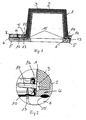
- the layer of mineral wool 3 is formed by plate-like parts of mineral wool, which are introduced in the form of a bottom part and in the form of wall parts in the housing and which are held in a positionally secured by the insulating layer forming material 2.
- a free edge of mineral wool 3 is provided, which is filled by the material forming the insulating layer 2, which is firmly connected in this area directly to the edge of the housing 1, for example glued.
- This area is designated 4.
- Such a molded part is installed in a false ceiling for fire protection purposes.
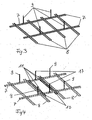
- the lower ceiling consists of a preferably two-layered plate element 5, 6 of fire and heat resistant material, such as plasterboard. This plate element 5, 6 is held on a support structure, which in FIGS.
- first metal support profiles 7 and second metal support profiles 8 are provided, which are interconnected at the intersection points.
- the support profiles 7 are fastened by means of band-like or anchor-like fastening parts 9 to a building ceiling or the like.
- the plate element 5, 6 has an opening which is covered by the molded part (1, 2, 3). This is supported on the back of the plate element 5, 6 at this.
- the rear side of the plate element next to the opening and adjacent to the edges of the molded part, which covers the opening the arrangement of two parallel third metal support profiles 10 are provided, which are firmly connected to the crossing these extending first metal support profiles 7 in the crossing region at 11.
- the third support profiles 10 are fastened to the plate element 5, 6 by means of fastening means.
- fastening means 12 serve as fastening means 12, 13 tapping screws.
- the mouth edge of the housing forming the molding 1 is also fastened by means of fastening means 14 to a respective adjacent leg of a third metal support profile 10.
- the fastening means 14 tapping screws. These tapping screws can be inserted from the outside, as in FIG. 1 right, or from the inside, as in FIG. 1 left, where appropriate, a placeholder in the region of the layers 2, 3 is provided in order to position the fastener there after removal of the placeholder can.
- a circumferential bead 15 is applied from fire protection putty.
- additional bracket 16 are attached to the side walls of the housing 1, for example dotted or screwed, which grab in the desired mounting position on legs or webs of the third metal support profiles 10, as in particular FIG. 2 and FIG. 5 is apparent.
- 7 band-like or anchor-like fasteners 17 are arranged on the first metal support profiles, in the next to the wall of the housing 1 located portion of the first metal support profiles 7, wherein these fasteners 17 are attached to the building ceiling or the like.
- the first supports 7 are fastened by means of fastening elements 9 to the ceiling and subsequently the metal support profiles 8 are connected to the metal support profiles 7 at the crossing points.
- the third metal support profiles 10 can be arranged between two metal support profiles 8 and connected at the intersection points with the metal support profiles 7, wherein additional Ceiling fasteners 17 are secured in the region of the metal support profiles 7, which are adjacent to the molded part to be fastened.
- the workflow is in FIGS. 3 and 4 illustrated.
- the molded part in the form of the housing 1 with the brackets 16 are suspended on the third metal support profiles 10, as in FIG. 5 is illustrated.
- connection lines can be guided by perforations of the molding, which are not particularly shown in the drawing.
Description
Die Erfindung betrifft ein Formteil, insbesondere kastenförmiges oder topfförmiges Formteil, für Brandschutzzwecke mit einer vorderseitigen Öffnung zur Anordnung von Installationsteilen oder elektrotechnischen Bauteilen, insbesondere einer Leuchte, wobei das Formteil aus einem formstabilen Gehäuse aus nichtbrennbarem Material, insbesondere Metallblech, das innenseitig ein eine Dämmschicht bildendes Material aufweist, welches unter Einwirkung von Hitze und/oder Feuer aufbläht und/oder eine Karbonsperrschicht bildet.The invention relates to a molded part, in particular box-shaped or cup-shaped molded part, for fire protection purposes with a front opening for the arrangement of installation parts or electrical components, in particular a lamp, wherein the molded part of a dimensionally stable housing made of non-combustible material, in particular sheet metal, the inside forming an insulating layer Material which inflates under the action of heat and / or fire and / or forms a Karbonsperrschicht.
Ein derartiges Formteil ist aus der
Der Erfindung liegt die Aufgabe zu Grunde, ein Formteil gattungsgemäßer Art zu schaffen, welches als komplette Brandschutzeinheit eingesetzt werden kann, einen großen Einbauraum für beliebige Installationsteile oder elektrische Bauteile zur Verfügung stellt, insbesondere für eine großdimensionierte elektrische Leuchteinheit, wobei das Formteil kostengünstig und relativ leichtgewichtig ausgebildet sein soll und eine sichere Brandabschottung ermöglicht.The invention is based on the object to provide a molded part of the generic type, which can be used as a complete fire protection unit, a large installation space for any installation parts or electrical components available, especially for a large-sized electrical lighting unit, the molding cost and relatively lightweight should be trained and allows a safe fire barrier.
Zur Lösung dieser Aufgabe wird vorgeschlagen, dass zwischen der Dämmschicht und der Gehäusewandung eine Schicht aus Mineralwolle, insbesondere Steinwolle, angeordnet ist.To solve this problem it is proposed that a layer of mineral wool, especially rock wool, is arranged between the insulating layer and the housing wall.
Das Gehäuse kann entsprechend seinem Einsatzzweck ein großdimensioniertes Blechgehäuse mit einseitiger offener Mündung sein, wobei das Gehäuse vorzugsweise quaderförmig ausgebildet ist. Dadurch, dass als Brandschutzmaterial einerseits eine Mineralwolleschicht bzw. Steinwolleschicht und andererseits eine diese Mineralwolle- oder Steinwolle-Schicht abdeckende Schicht aus Material aufweist, welches unter Einwirkung von Hitze und/oder Feuer aufbläht, wird ein wesentlicher Vorteil erreicht. Durch die Kombination dieser beiden Materialien ist bei geringer Wandstärke der nach Art eines Sandwiches aufgebauten Schicht eine optimale Wärmeisolierung erreicht. Zusätzlich wird das Eigengewicht relativ gering gehalten, weil durch die Materialkombination ein geringeres Eigengewicht erreicht wird; als in dem Fall, dass die Materialschicht lediglich aus dem eine Dämmschicht bildenden, unter Einwirkung von Hitze oder Feuer aufblähbaren Material bestünde. Die Herstellungskosten sind minimiert, weil das relativ teure, die Dämmschicht bildende aufblähbare Material nur in relativ geringer Wandstärke eingesetzt werden muss, während das kostengünstigere Mineralwolle- oder Steinwollematerial ihrem Einsatzzweck entsprechend dimensioniert eingesetzt werden kann. Zudem wird durch diese Kombination die Gesamtwandstärke relativ gering gehalten, so dass der Einbauraum, der im Gehäuse nach Einbringen der Materialschichten zur Verfügung steht, relativ groß gehalten ist. Bei einem Aufbau allein mit Mineralwolle oder Steinwolle wäre die Wandschicht erheblich stärker, so dass der Einbauraum im Gehäuse erheblich eingeschränkt wäre.The housing may be according to its purpose a large-sized sheet metal housing with one-sided open mouth, the housing is preferably formed cuboid. The fact that the fire protection material on the one hand a mineral wool layer or rock wool layer and on the other hand has a mineral wool or rock wool layer covering layer of material which inflates under the action of heat and / or fire, a significant advantage is achieved. Due to the combination of these two materials, optimum thermal insulation is achieved with a small wall thickness of the sandwich-type layer. In addition, the weight is kept relatively low, because a lower weight is achieved by the combination of materials; as in the case that the material layer only from the insulating layer forming, under the action of heat or fire inflatable material would consist. The production costs are minimized because the relatively expensive, the insulating layer forming inflatable material must be used only in relatively small wall thickness, while the cost-effective mineral wool or rock wool material can be used according to their intended use dimensioned. In addition, this combination is the Total wall thickness kept relatively low, so that the installation space, which is available in the housing after introducing the material layers, is kept relatively large. In a construction with mineral wool or rock wool alone, the wall layer would be considerably stronger, so that the installation space would be considerably restricted in the housing.
Aus der
Bevorzugt ist zudem bei einem Formteil in Form eines mit einem Bodenteil und einem Wandteil bestehenden Gehäuses vorgesehen, dass die Schicht aus Mineralwolle durch plattenartige Teile aus Mineralwolle gebildet ist, die in Form eines Bodenteils und in Form von Wandteilen in das Gehäuse eingebracht sind und durch das die Dämmschicht bildende Material lagegesichert gehalten sind.Preference is also provided in a molding in the form of a housing provided with a bottom part and a wall part that the layer of mineral wool is formed by plate-like parts of mineral wool, which are introduced in the form of a bottom part and in the form of wall parts in the housing and through the the insulating layer forming material are kept secure in position.
Durch diese Ausbildung ist es möglich, zunächst die Schicht aus Mineralwolle in der Gehäuse einzubringen, in- dem die plattenartigen Teile in das Gehäuse eingebracht werden und allein durch ihre Zuschnittsform in einer Vormontage-Position gehalten sind. Anschließend kann das die Dämmschicht bildende Material aufgebracht werden, wodurch die endgültige Lagesicherung der Teile zueinander erreicht wird.With this design, it is possible to first introduce the layer of mineral wool in the housing, in which the plate-like parts are introduced into the housing and are held solely by their blank form in a pre-assembly position. Subsequently, the insulating layer forming material can be applied, whereby the final position assurance of the parts is achieved to each other.
Insbesondere ist für die Lagesicherung der Schichten innerhalb des Gehäuses vorgesehen, dass das Gehäuse einen Mündungsrand aufweist und im Bereich des Mündungsrandes des Gehäuses ein von Mineralwolle freier Rand vorgesehen ist, der durch das die Dämmschicht bildende Material gefüllt ist, welches unmittelbar mit dem Rand des Gehäuses verbunden, insbesondere verklebt, ist.In particular, it is provided for the position assurance of the layers within the housing that the housing has a mouth edge and a mineral wool-free edge is provided in the region of the mouth edge of the housing, which is filled by the insulating layer forming material, which is directly connected to the edge of the housing, in particular glued.
Dadurch, dass die Frontkante mit dem die Dämmschicht bildenden Material übergossen ist, wird erreicht, dass im Brandfall der Raumabschluss gewährt bleibt. Die übergossene Frontkante wirkt wie eine nachschäumende Dichtlippe und stellt den Raumabschluss sicher. Darüberhinaus wird durch das die Dämmschicht bildende Material das Mineralwolleplattenmaterial an der Innenseite des Metallgehäuses fixiert.The fact that the front edge is doused with the material forming the insulating layer, ensures that in case of fire, the room closure is granted. The over-molded front edge acts like a nachschäumende sealing lip and ensures the space closure. Moreover, the mineral wool plate material is fixed to the inside of the metal case by the material forming the insulating layer.
Das die Dämmschicht bildende Material wird bei der Herstellung als gießfähiges Material auf die Mineralwollschicht und den Gehäuserand aufgetragen.The material forming the insulating layer is applied to the mineral wool layer and the edge of the shell during production as a castable material.
Gegenstand der Erfindung ist ferner eine Unterdecke für Brandschutzzwecke. Erfindungsgemäß besteht diese aus einem einlagig oder vorzugsweise mehrlagig ausgebildeten Plattenelement aus feuer- und hitzebeständigem Material, beispielsweise Gipskartonplatten, einer das Plattenelement haltenden Tragkonstruktion mit zueinander kreuzend verlegten ersten und zweiten Metalltragprofilen, an denen die Bestandteile des Plattenelementes in geeigneter Form befestigt sind. Ferner sind bandartige oder ankerartige Befestigungsteile vorgesehen, die einerseits vorzugsweise an den ersten Metalltragprofilen befestigt sind und andererseits an der Gebäudedecke oder dergleichen Tragteilen befestigbar sind, so dass die Konstruktion einer untergehängten Decke realisiert ist. Das Plattenelement weist mindestens eine Öffnung auf, die von einem Formteil nach einem der Ansprüche 1 bis 3 überdeckt ist. Das Formteil stützt sich rückseitig des Plattenelementes an diesem ab. Rückseitig des Plattenelementes sind neben der Öffnung und neben den Rändern des Formteils, welche die Öffnung überdeckt, zwei zueinander parallele dritte Metalltragprofile angeordnet, die mit zu diesen kreuzend verlaufenden ersten Metalltragprofilen oder verbunden sind, oder es ist mindestens ein drittes Metalltragprofil angeordnet, das mit einem ersten oder zweiten Metalltragprofil verbunden ist, und mit Abstand zu einem ersten oder zweiten Metallprofil parallel zu diesem ausgerichtet ist, wobei die dritten Tragprofile oder die die Öffnung seitlich umgebenden Profile, nämlich ein drittes Tragprofil und ein dazu parallel verlaufendes erstes oder zweites Metallprofil zusätzlich mittels Befestigungsmitteln an dem Plattenelement befestigt sind und der Mündungsrand des das Formteil bildenden Gehäuses ist mittels Befestigungsmitteln an einem jeweils benachbarten Schenkel eines ersten, zweiten oder dritten Metalltragprofiles befestigt.The invention also relates to a false ceiling for fire protection purposes. According to the invention this consists of a single-layer or preferably multi-layered plate member made of fire and heat resistant material, such as plasterboard, a support member holding the plate member with intersecting laid first and second metal support profiles to which the components of the plate member are secured in a suitable form. Furthermore, band-like or anchor-like fastening parts are provided, which are preferably fastened on the one hand to the first metal support profiles and on the other hand can be fastened to the building ceiling or similar supporting parts, so that the construction of a suspended ceiling is realized. The plate element has at least one opening, which is covered by a molding according to one of
Bevorzugt ist zudem vorgesehen, dass zwischen dem im Bereich des Mündungsrandes des Gehäuses vorgesehenen, die Dämmschicht bildenden Material und dem diese untergreifenden Bereich des Plattenelementes eine umlaufende Raupe aus Brandschutzkitt aufgebracht ist.Preferably, it is also provided that between the provided in the region of the mouth edge of the housing, the insulating layer forming material and this under cross-section of the plate member, a circumferential bead of fire-resistant putty is applied.
Des Weiteren ist bevorzugt vorgesehen, dass an den Seitenwänden des Gehäuses Haltewinkel befestigt sind, die über Schenkel oder Stege der dritten Metalltragprofile greifen.Furthermore, it is preferably provided that on the side walls of the housing brackets are attached, which engage over legs or webs of the third metal support profiles.
Zudem ist bevorzugt vorgesehen, dass an den ersten oder zweiten Metalltragprofilen bandartige oder ankerartige Befestigungselemente angeordnet sind, und zwar im neben der Wandung des Gehäuses befindlichen Bereich der ersten Metalltragprofile, die an der Gebäudedecke oder dergleichen Tragteilen befestigt sind.In addition, it is preferably provided that band-like or anchor-like fastening elements are arranged on the first or second metal support profiles, specifically in the area of the first metal support profiles adjacent to the wall of the housing, which are fastened to the building ceiling or similar supporting parts.
Besonders ist bevorzugt, dass die Unterkante des Gehäuses mit der Anlagefläche der ersten, zweiten und/oder dritten Metalltragprofile an dem Plattenelement fluchtet.It is particularly preferred that the lower edge of the housing is aligned with the contact surface of the first, second and / or third metal support profiles on the plate member.
Zudem kann vorgesehen sein, dass als Befestigungsmittel Schrauben, insbesondere Blechschrauben, angeordnet sind.In addition, it can be provided that screws, in particular sheet-metal screws, are arranged as fastening means.
Bei der erfindungsgemäßen Konstruktion wird zunächst die Unterdecke in herkömmlicher Art aufgebaut, wobei die ersten und zweiten Metalltragprofile über Anker oder dergleichen an der Decke oder dergleichen Tragteil befestigt werden und die Plattenelemente an diesen Profilen fixiert werden. Über der Öffnung, die für die Installation einer Leuchte oder dergleichen vorgesehen ist, wird das Formteil positioniert. Dabei ist nahe zweier zueinander paralleler Randkanten der rechteckigen Öffnung die Anordnung von dritten Metalltragprofilen vorgesehen, die die ersten Tragprofile kreuzen und im Kreuzungspunkt an diesen befestigt sind. Vorzugsweise wird das Gehäuse mit seiner Mündung niveaugleich zur Unterkante der Befestigungsprofile (dritte Metalltragprofile) ausgerichtet. Zusätzlich wird das Gehäuse mittels jeweils zwei an seinen Seiten befestigten, beispielsweise angeschraubten oder angepunkteten Winkeln auf die zusätzlichen dritten Metalltragprofile gehängt. Um die niveaugleiche Ausrichtung des Gehäuses zu fixieren, werden Blechschrauben seitlich von innen oder außen verschraubt, so dass eine Verbindung des Gehäuses mit dem dritten Metalltragprofil hergestellt ist. Das dritte Metalltragprofil ist zusätzlich durch Schrauben an den Plattenelementen befestigt, die die Plattenelemente durchdringen, so dass eine feste Fixierung des gesamten fertigen Bauteiles an dem Plattenelement gewährleistet ist. Es ist damit nicht möglich, das Formteil zu verschieben oder hochzudrücken. Die Frontkante des Gehäuses ist mit dem die Dämmschicht bildenden Material übergossen, so dass im Brandfall der Raumabschluss gewährt bleibt. Die übergossene Frontkante wirkt wie eine nachschäumende Dichtlippe und stellt den Raumabschluss sicher. Die umlaufende Raupe aus Brandschutzkitt unterstützt diesen Vorgang und bewirkt zusätzlich eine Verklebung der Teile mit dem Plattenmaterial.In the construction according to the invention, first, the sub-ceiling is constructed in a conventional manner, wherein the first and second metal support profiles are attached via anchors or the like to the ceiling or the like support member and the plate elements are fixed to these profiles. Above the opening, which is provided for the installation of a lamp or the like, the molding is positioned. In this case, the arrangement of third metal support profiles is provided near two mutually parallel edges of the rectangular opening, which intersect the first support profiles and are secured at the intersection point to this. Preferably, the housing with its mouth is level with the bottom edge of the mounting profiles (third metal support profiles) aligned. In addition, the housing is hung by means of two each attached to its sides, for example screwed or dotted angles on the additional third metal support profiles. In order to fix the level alignment of the housing, tapping screws are screwed laterally from the inside or outside, so that a connection of the housing is made to the third metal support profile. The third metal support profile is additionally fastened by screws to the plate elements, which penetrate the plate elements, so that a firm fixation of the entire finished component is ensured on the plate member. It is thus not possible to move the molding or push up. The front edge of the housing is covered with the insulating layer forming material, so that in case of fire, the space closure is granted. The over-molded front edge acts like a nachschäumende sealing lip and ensures the space closure. The encircling caterpillar made of fire-retardant cement supports this process and additionally causes the parts to stick to the plate material.
Es ist möglich, die ersten und zweiten Metalltragprofile in einer gemeinsamen Ebene anzuordnen und miteinander zu verbinden oder die Metalltragprofile übereinander in zwei Ebenen anzuordnen und im Kreuzungsbereich zu verbinden.It is possible to arrange the first and second metal support profiles in a common plane and to connect them together or to arrange the metal support profiles on top of each other in two levels and to connect in the crossing area.
Auch können die den parallelen Randkanten der rechteckigen Öffnung benachbarten Profile durch ein drittes Metalltragprofil und durch ein erstes oder ein zweites Metalltragprofil gebildet sein. Das Gehäuse wird dann auf die Profile gehängt und in der oben beschriebenen Weise an diesen befestigt, wobei auch die Profile in analoger Weise mit den Plattenelementen befestigt werden.Also, the profiles adjacent to the parallel marginal edges of the rectangular opening can by a third metal support profile and be formed by a first or a second metal support profile. The housing is then hung on the profiles and secured thereto in the manner described above, the profiles also being secured in an analogous manner to the panel members.
Ein Ausführungsbeispiel der Erfindung ist in der Zeichnung dargestellt und im Folgenden näher beschrieben. Es zeigt:
Figur 1- ein Formteil, welches an einer Unterdecke befestigt ist, in der Montagesolllage im Schnitt gesehen;
Figur 2- eine Ausschnittsvergrößerung II der
Figur 1 Figur 3- ein Teil einer Unterdeckenkonstruktion in Ansicht;
Figur 4- eine ergänzte Unterdeckenkonstruktion in der Ansicht gemäß
Figur 3 Figur 5- die Unterdeckenkonstruktion mit eingesetztem Formteil in der Ansicht wie
Figur 3
- FIG. 1
- a molding, which is attached to a false ceiling, seen in the assembly target position in section;
- FIG. 2
- an enlarged detail II of
FIG. 1 ; - FIG. 3
- a part of a lower roof construction in view;
- FIG. 4
- a supplemented lower ceiling construction in the view according to
FIG. 3 seen; - FIG. 5
- the lower ceiling construction with inserted molding in the view like
FIG. 3 seen.
In der Zeichnung ist ein quaderförmiges Formteil mit sich zur vorderseitigen Öffnung erweiternden Wandteilen gezeigt. Die vorderseitige Öffnung dient zur Installation von elektrotechnischen Bauteilen, beispielsweise einer großflächigen Leuchte. Das Formteil besteht aus einem formstabilen Gehäuse 1 aus Stahlblech. Innenseitig weist das Gehäuse 1 ein eine Dämmschicht bildendes Material 2 auf, welches unter Einwirkung von Hitze und/oder Feuer aufbläht oder eine Karbonsperrschicht bildet. Zwischen der Dämmschicht 2 und der Gehäusewandung des Gehäuses 1 ist eine Schicht 3 aus Mineralwolle oder Steinwolle angeordnet. Vorzugsweise ist die Schicht aus Mineralwolle 3 durch plattenartige Teile aus Mineralwolle gebildet, die in Form eines Bodenteils und in Form von Wandteilen in das Gehäuse eingebracht sind und die durch das die Dämmschicht bildende Material 2 lagegesichert gehalten sind. Im Bereich des Mündungsrandes des Gehäuses 1 ist ein von Mineralwolle 3 freier Rand vorgesehen, der durch das die Dämmschicht bildende Material 2 gefüllt ist, welches in diesem Bereich unmittelbar mit dem Rand des Gehäuses 1 fest verbunden, beispielsweise verklebt ist. Dieser Bereich ist mit 4 bezeichnet. Ein solches Formteil ist in eine Unterdecke für Brandschutzzwecke eingebaut. Die Unterdecke besteht aus einem vorzugsweise zweilagig ausgebildeten Plattenelement 5, 6 aus feuer- und hitzebeständigem Material, beispielsweise Gipskartonplatten. Dieses Plattenelement 5, 6 ist an einer Tragkonstruktion gehalten, die in
Zwischen dem im Bereich des Mündungsrandes des Gehäuses 1 vorgesehenen die Dämmschicht bildenden Material (4) und dem diesen untergreifenden Bereich des Plattenelementes 6 ist eine umlaufende Raupe 15 aus Brandschutzkitt aufgebracht.Between the provided in the region of the mouth edge of the
Zur Positionierung des Gehäuses 1 sind an den Seitenwänden des Gehäuses 1 noch zusätzliche Haltewinkel 16 befestigt, beispielsweise angepunktet oder angeschraubt, welche in der Montagesollposition über Schenkel oder Stege der dritten Metalltragprofile 10 greifen, wie insbesondere aus
Nach der Installation ist es möglich, in den offenen Raum des Formteiles 1 von unten her eine großformatige Leuchte oder dergleichen unterzubringen. Entsprechende Anschlussleitungen können durch Lochungen des Formteils geführt werden, die in der Zeichnung nicht besonders dargestellt sind.After installation, it is possible to accommodate in the open space of the
Claims (9)
- A formed part, in particular a box-shaped or pot-shaped formed part, for fire protection comprising a front-side opening for the arrangement of installation parts or electrotechnical components, in particular a light, the formed part consisting of a dimensionally stable housing (1) of an incombustible material, in particular sheet metal, which on the inside has a material (2) that forms an insulating layer, and that swells up under the action of heat and/or fire and/or forms a carbon barrier layer, characterized by that between the insulating layer (2) and the housing wall, a layer (3) made of mineral wool, in particular rock wool, is arranged.
- The formed part according to claim 1 configured as a housing (1) comprising a floor part and a wall part, characterized by that the layer (3) made of mineral wool is formed by panel-type parts made of mineral wool that are provided in the form of a floor part and in the form of wall parts in the housing (1) and are positionally secured by the material (2) that forms the insulating layer.
- The formed part according to claim 1 or 2, characterized by that the housing (1) has a mouthpiece edge, and that in the area of the mouthpiece edge of the housing (1), an edge being free from mineral wool (3) is provided that is filled by the material (2) that forms an insulating layer, which is immediately connected, in particular glued, with the edge of the housing (1).
- A false ceiling for fire protection, consisting of a single-layer or preferably multi-layer panel element (5, 6) made of a material that is resistant to fire and heat, in particular gypsum plaster boards, as well as a supporting structure that holds the panel element (5, 6) with first and second metal supporting profiles (7, 8) laid in a crossing manner, at which the components of the panel element (5, 6) are attached and which are attached by means of band-like or anchor-like fastening parts (9) at a ceiling of a building or similar supporting parts, wherein the panel element (5, 6) has at least one opening that that is covered by a formed part according to one of claims 1 to 3, which at the rear side of the panel element (5, 6) is supported thereon, wherein at the rear side of the panel element (5, 6) beside the opening and beside the edges of the formed part covering the opening, two parallel third metal supporting profiles (10) are arranged that are connected with first metal supporting profiles (7) or (8) extending in an crossing manner with respect thereto, or at least one third metal supporting profile (10) is arranged that is connected with a first or second metal supporting profile (7, 8), and is oriented in a spaced manner to a first or second metal profile (7, 8) in parallel thereto, wherein the third supporting profiles (10) or the profiles laterally surrounding the opening, namely a third supporting profile (10) and a first or second metal profile (7, 8) extending in parallel thereto are additionally fastened by means of fastening means (12, 13) at the panel element (5, 6), and the mouthpiece edge of the housing (1) forming the formed part is fastened by means of fastening means (14) at a respectively adjacent leg of a first, second or third metal supporting profile (7, 8, 10).
- The false ceiling according to claim 4, characterized by that between the material (2) provided in the area (4) of the mouthpiece edge of the housing (1) and forming the insulating layer and the area of the panel element (5, 6) situated therebelow a circumferential bead (15) of fire protection putty is applied.
- The false ceiling according to claim 4 or 5, characterized by that at the side walls of the housing (1), mounting brackets (16) are fastened that engage over leg or webs of the third metal supporting profiles (10).
- The false ceiling according to one of claims 4 to 6, characterized by that at the first or second metal supporting profiles (7, 8), band-like or anchor-like fastening parts (17) are arranged, namely in the area of the first metal supporting profiles (7) situated beside the wall of the housing (1), which are fastened at the ceiling of the building or similar supporting parts.
- The false ceiling according to one of claims 4 to 7, characterized by that the lower edge of the housing (1) is flush with the contact surface of the first, second and/or third metal supporting profiles (7, 8, 10) at the panel element (5, 6).
- False ceiling according to one of claims 4 to 8, characterized by that screws are used as fastening means (14, 12, 13), in particular self-tapping screws.
Applications Claiming Priority (2)
| Application Number | Priority Date | Filing Date | Title |
|---|---|---|---|
| DE102004007453 | 2004-02-13 | ||
| DE102004007453.4A DE102004007453B4 (en) | 2004-02-13 | 2004-02-13 | molding |
Publications (3)
| Publication Number | Publication Date |
|---|---|
| EP1564339A2 EP1564339A2 (en) | 2005-08-17 |
| EP1564339A3 EP1564339A3 (en) | 2009-04-15 |
| EP1564339B1 true EP1564339B1 (en) | 2012-09-12 |
Family
ID=34684069
Family Applications (1)
| Application Number | Title | Priority Date | Filing Date |
|---|---|---|---|
| EP20040009626 Expired - Lifetime EP1564339B1 (en) | 2004-02-13 | 2004-04-23 | Fire resistant enclosure for installation or electro-technical elements |
Country Status (2)
| Country | Link |
|---|---|
| EP (1) | EP1564339B1 (en) |
| DE (1) | DE102004007453B4 (en) |
Families Citing this family (6)
| Publication number | Priority date | Publication date | Assignee | Title |
|---|---|---|---|---|
| DE202006015399U1 (en) * | 2006-10-06 | 2008-02-14 | Viessmann Kältetechnik AG | Prefabricated wall panel |
| EP2527555B1 (en) | 2011-05-24 | 2016-03-30 | Metalicht B.V. | Tile for a suspended ceiling system |
| CN103374991A (en) * | 2013-07-25 | 2013-10-30 | 苏州金螳螂建筑装饰股份有限公司 | Shaped gypsum board suspended ceiling |
| DE202014105845U1 (en) * | 2014-12-04 | 2016-03-07 | Kaiser Gmbh & Co Kg | Hollow ceiling with fire enclosure and fire enclosure |
| DE102018101461A1 (en) * | 2018-01-23 | 2019-07-25 | Matthias Trunk | Fire Case |
| CN115042912B (en) * | 2022-07-15 | 2023-09-26 | 靖江亚泰船用物资有限公司 | Fire-resistant mounting structure of B15-level composite rock wool board is built on boats and ships |
Family Cites Families (6)
| Publication number | Priority date | Publication date | Assignee | Title |
|---|---|---|---|---|
| US4210070A (en) * | 1978-03-06 | 1980-07-01 | Dayus Barry R | Ceiling fixture with thermal protection |
| DE3622109A1 (en) * | 1986-07-02 | 1988-01-07 | Promat Gmbh | Luminaire for rooms exposed to fire hazard |
| DE9318416U1 (en) | 1993-12-02 | 1994-03-17 | Promat Gmbh | Suspended ceiling for fire protection purposes |
| US6105334A (en) * | 1997-09-16 | 2000-08-22 | Logic Construction Systems, L.L.C. | Fire resistant lighting enclosure |
| GB2345125B (en) * | 1998-12-23 | 2002-05-01 | Tenmat Ltd | Intumescent downlighter cover and method of manufacturing same |
| DE10223904A1 (en) * | 2002-05-29 | 2003-12-11 | Kaiser Gmbh & Co Kg | Suspended ceiling for fire protection purposes |
-
2004
- 2004-02-13 DE DE102004007453.4A patent/DE102004007453B4/en not_active Expired - Lifetime
- 2004-04-23 EP EP20040009626 patent/EP1564339B1/en not_active Expired - Lifetime
Also Published As
| Publication number | Publication date |
|---|---|
| DE102004007453B4 (en) | 2015-12-03 |
| EP1564339A3 (en) | 2009-04-15 |
| DE102004007453A1 (en) | 2005-09-15 |
| EP1564339A2 (en) | 2005-08-17 |
Similar Documents
| Publication | Publication Date | Title |
|---|---|---|
| EP2314782A2 (en) | Acoustic absorber and additional frame section for an acoustic absorber | |
| DE3631993C2 (en) | Fire-resistant cover | |
| EP1564339B1 (en) | Fire resistant enclosure for installation or electro-technical elements | |
| DE2611033C2 (en) | Fire-resistant lightweight partition wall for rooms of buildings | |
| EP1367191B1 (en) | Ceiling, wall or floor panel for fire protection | |
| DE19714625C2 (en) | Wooden panel building structure | |
| DE2315213C3 (en) | Curtain wall and method of installing the same | |
| DE19710789A1 (en) | Building roof | |
| DE202004002362U1 (en) | Molded enclosure for electricals comprises sheet metal housing lined with heat-swelling insulating material plus interposed mineral wool plates. | |
| EP1491702B1 (en) | Inspection cover | |
| DE3514267C2 (en) | Suspended ceiling for building rooms, especially corridors | |
| DE102007027807A1 (en) | Dry construction partition wall for changing room usage, has inspection glass formed as fire protection inspection glass, where inspection glass is supported on frame by elastic spring unit i.e. rock wool layer, in floating suspension | |
| DE10125349B4 (en) | Wooden wall panel | |
| EP1319790B1 (en) | Anchor for door and window | |
| DE20219324U1 (en) | building basement | |
| AT500659B1 (en) | BRAND SPREAD-INHIBITING (R) WAND BZW. WALL SECTION BASED ON PLASTERBOARD WALL PLATES | |
| DE19754179C1 (en) | False ceiling panel mounting rail for wall | |
| DE102004050442B4 (en) | Housing, in particular instrument house for electrical instruments and analyzers | |
| EP1643050A2 (en) | Fire resistant false ceiling for escape ways in buildings | |
| AT413721B (en) | FORM BODY FOR PREPARING INSTALLATIONS | |
| DE102014208933A1 (en) | Fitting for connecting a Kehl bar with a roof rafter | |
| DE2741946A1 (en) | FIRE RESISTANT BASE CEILING | |
| DE4420872C2 (en) | Fire protection ceiling panel element for bandraster suspended ceilings | |
| DE102019116533A1 (en) | Ceiling arrangement | |
| DE8605594U1 (en) | Wall element for a kit for lining and dividing a room |
Legal Events
| Date | Code | Title | Description |
|---|---|---|---|
| PUAI | Public reference made under article 153(3) epc to a published international application that has entered the european phase |
Free format text: ORIGINAL CODE: 0009012 |
|
| AK | Designated contracting states |
Kind code of ref document: A2 Designated state(s): AT BE BG CH CY CZ DE DK EE ES FI FR GB GR HU IE IT LI LU MC NL PL PT RO SE SI SK TR |
|
| AX | Request for extension of the european patent |
Extension state: AL HR LT LV MK |
|
| PUAL | Search report despatched |
Free format text: ORIGINAL CODE: 0009013 |
|
| AK | Designated contracting states |
Kind code of ref document: A3 Designated state(s): AT BE BG CH CY CZ DE DK EE ES FI FR GB GR HU IE IT LI LU MC NL PL PT RO SE SI SK TR |
|
| AX | Request for extension of the european patent |
Extension state: AL HR LT LV MK |
|
| RIC1 | Information provided on ipc code assigned before grant |
Ipc: E04B 9/00 20060101ALI20090310BHEP Ipc: F21V 25/12 20060101ALI20090310BHEP Ipc: E04B 1/94 20060101AFI20050610BHEP Ipc: F21V 15/01 20060101ALI20090310BHEP |
|
| 17P | Request for examination filed |
Effective date: 20090430 |
|
| 17Q | First examination report despatched |
Effective date: 20090706 |
|
| AKX | Designation fees paid |
Designated state(s): DE |
|
| REG | Reference to a national code |
Ref country code: DE Ref legal event code: R079 Ref document number: 502004013739 Country of ref document: DE Free format text: PREVIOUS MAIN CLASS: E04B0001940000 Ipc: F21V0025000000 |
|
| GRAP | Despatch of communication of intention to grant a patent |
Free format text: ORIGINAL CODE: EPIDOSNIGR1 |
|
| GRAJ | Information related to disapproval of communication of intention to grant by the applicant or resumption of examination proceedings by the epo deleted |
Free format text: ORIGINAL CODE: EPIDOSDIGR1 |
|
| RIC1 | Information provided on ipc code assigned before grant |
Ipc: E04B 9/00 20060101ALI20120511BHEP Ipc: F21V 25/12 20060101ALI20120511BHEP Ipc: E04B 1/94 20060101ALI20120511BHEP Ipc: F21V 25/00 20060101AFI20120511BHEP Ipc: F21V 15/01 20060101ALI20120511BHEP |
|
| GRAP | Despatch of communication of intention to grant a patent |
Free format text: ORIGINAL CODE: EPIDOSNIGR1 |
|
| GRAS | Grant fee paid |
Free format text: ORIGINAL CODE: EPIDOSNIGR3 |
|
| GRAA | (expected) grant |
Free format text: ORIGINAL CODE: 0009210 |
|
| AK | Designated contracting states |
Kind code of ref document: B1 Designated state(s): DE |
|
| REG | Reference to a national code |
Ref country code: DE Ref legal event code: R096 Ref document number: 502004013739 Country of ref document: DE Effective date: 20121108 |
|
| PLBE | No opposition filed within time limit |
Free format text: ORIGINAL CODE: 0009261 |
|
| STAA | Information on the status of an ep patent application or granted ep patent |
Free format text: STATUS: NO OPPOSITION FILED WITHIN TIME LIMIT |
|
| 26N | No opposition filed |
Effective date: 20130613 |
|
| REG | Reference to a national code |
Ref country code: DE Ref legal event code: R097 Ref document number: 502004013739 Country of ref document: DE Effective date: 20130613 |
|
| PGFP | Annual fee paid to national office [announced via postgrant information from national office to epo] |
Ref country code: DE Payment date: 20230630 Year of fee payment: 20 |