EP1563992A2 - Druckform mit mehreren flächigen Funktionszonen - Google Patents
Druckform mit mehreren flächigen Funktionszonen Download PDFInfo
- Publication number
- EP1563992A2 EP1563992A2 EP05100599A EP05100599A EP1563992A2 EP 1563992 A2 EP1563992 A2 EP 1563992A2 EP 05100599 A EP05100599 A EP 05100599A EP 05100599 A EP05100599 A EP 05100599A EP 1563992 A2 EP1563992 A2 EP 1563992A2
- Authority
- EP
- European Patent Office
- Prior art keywords
- zone
- layer
- printing form
- energy
- absorption
- Prior art date
- Legal status (The legal status is an assumption and is not a legal conclusion. Google has not performed a legal analysis and makes no representation as to the accuracy of the status listed.)
- Granted
Links
Images
Classifications
-
- B—PERFORMING OPERATIONS; TRANSPORTING
- B41—PRINTING; LINING MACHINES; TYPEWRITERS; STAMPS
- B41N—PRINTING PLATES OR FOILS; MATERIALS FOR SURFACES USED IN PRINTING MACHINES FOR PRINTING, INKING, DAMPING, OR THE LIKE; PREPARING SUCH SURFACES FOR USE AND CONSERVING THEM
- B41N1/00—Printing plates or foils; Materials therefor
- B41N1/04—Printing plates or foils; Materials therefor metallic
- B41N1/08—Printing plates or foils; Materials therefor metallic for lithographic printing
-
- B—PERFORMING OPERATIONS; TRANSPORTING
- B41—PRINTING; LINING MACHINES; TYPEWRITERS; STAMPS
- B41C—PROCESSES FOR THE MANUFACTURE OR REPRODUCTION OF PRINTING SURFACES
- B41C1/00—Forme preparation
- B41C1/10—Forme preparation for lithographic printing; Master sheets for transferring a lithographic image to the forme
-
- B—PERFORMING OPERATIONS; TRANSPORTING
- B41—PRINTING; LINING MACHINES; TYPEWRITERS; STAMPS
- B41N—PRINTING PLATES OR FOILS; MATERIALS FOR SURFACES USED IN PRINTING MACHINES FOR PRINTING, INKING, DAMPING, OR THE LIKE; PREPARING SUCH SURFACES FOR USE AND CONSERVING THEM
- B41N1/00—Printing plates or foils; Materials therefor
- B41N1/12—Printing plates or foils; Materials therefor non-metallic other than stone, e.g. printing plates or foils comprising inorganic materials in an organic matrix
- B41N1/14—Lithographic printing foils
-
- Y—GENERAL TAGGING OF NEW TECHNOLOGICAL DEVELOPMENTS; GENERAL TAGGING OF CROSS-SECTIONAL TECHNOLOGIES SPANNING OVER SEVERAL SECTIONS OF THE IPC; TECHNICAL SUBJECTS COVERED BY FORMER USPC CROSS-REFERENCE ART COLLECTIONS [XRACs] AND DIGESTS
- Y10—TECHNICAL SUBJECTS COVERED BY FORMER USPC
- Y10T—TECHNICAL SUBJECTS COVERED BY FORMER US CLASSIFICATION
- Y10T428/00—Stock material or miscellaneous articles
- Y10T428/24—Structurally defined web or sheet [e.g., overall dimension, etc.]
- Y10T428/24802—Discontinuous or differential coating, impregnation or bond [e.g., artwork, printing, retouched photograph, etc.]
Definitions
- the present invention relates to a printing form with a plurality of flat functional zones according to the preamble of claim 1.
- printing plates are Printing plates, printing tapes, printing sleeves and surfaces of printing devices such.
- B. of printing cylinders (hereinafter generally referred to as printing plates) known which after a (re) imaging process carry image information and a applied ink according to the image information on a medium such. Eg paper transfer.
- Such printing forms often have a layered structure, i. H. are on a carrier applied to each other different layers, these layers special Functions, such as B. absorption or reflection of radiation and thermal insulation, can be assigned.
- the imaging process usually involves the full-surface or according to the image information controlled irradiation of energy, often laser are used.
- the printing form is at least pixel-wise heated by the radiated energy to the extent that their surface temperature locally exceeds a certain transition temperature and a surface chemical or surface physical process takes place, which leads to a change in the wetting property with water (or color).
- the surface of the printing form can be structured into hydrophilic and hydrophobic (or oleophobic and oleophilic) areas.
- an imageable wet offset printing plate is already known which has a layer structure.
- the printing form, or their photocatalytically and thermally variable material such.
- TiO 2 is photocatalytically hydrophilized on the surface with ultraviolet radiation photocatalytic and thermoblocked with infrared radiation thermally pixel by pixel, the heat energy is absorbed by absorption centers in the variable material or an absorption layer below this material.
- a first embodiment comprises a 1 to 30 micron thick top layer of TiO 2 , in which absorption centers (eg, nanoparticles of a semiconductor material) are dispersed in a fine, uniform distribution, and an underlayer of a material with high heat conduction and high heat capacity for reducing a to large lateral heat flow.
- absorption centers eg, nanoparticles of a semiconductor material
- a second embodiment comprises an only 0.5 to 5 micrometer thick upper layer of TiO 2 and a disposed below 1 to 5 micrometer thick absorption layer, from which the absorbed heat energy can flow back into the upper layer.
- the two layers on a support for. B. Aluminum, with an additional 1 to 30 microns thick Insulation layer can reduce the heat conduction to the carrier.
- an imageable offset printing plate which a Polymer surface, an underneath thin, less than 25 nanometers thick Metal layer, z.
- Metal layer As titanium, for the absorption of infrared radiation and a bad having thermally conductive carrier with infrared radiation reflective pigments.
- Imaging of the printing form is applied to this infrared laser radiation, which in the two upper layers penetrate and on the carrier back into the metal layer is reflected.
- the thin metal layer may additionally be provided with an antireflective coating, z. B. of a metal oxide, be provided for the infrared radiation.
- US Pat. No. 6,073,559 discloses an infrared-imageable offset printing plate having a 10 to 500 nanometers thick hydrophilic layer of a metal-non-metal mixture, a 5 to 500 nanometers thick metal layer, z.
- titanium for the absorption of the coupled Infrared radiation, which forms an oxide on its surface, an oleophilic, hard Ceramic layer as a thermal insulator and a support. On the surface of the Ceramic layer, the incident radiation is reflected back into the metal layer.
- the printing form has a as Absorption layer serving outer layer, for. B. a 0.5 to 5 microns thick Titanium layer, and serving as an insulating layer inner layer, for. For example, a 10-100 Micrometer thick glass or ceramic layer, on. Both layers are on a support added.
- the absorption layer has a low heat capacity and density and the insulation layer additionally has a low thermal conductivity.
- Another printing form is the subject of unpublished DE 102 27 054.
- This reusable printing form has a metal oxide surface, z. Legs Titanium oxide surface treated with an amphiphilic organic compound, the polar region has an acidic character.
- By selective pointwise energy supply, z. B. by infrared radiation an image can be generated on the printing form and through large-scale energy supply, z. B. by ultraviolet radiation, the picture can again to be deleted.
- the subject of unpublished DE 103 54 341 relates to a method for patterning a printing form surface which is a hydrophilizable polymer having, whereby by energy supply, for. B. by means of laser radiation, on a range of Printing plate surface in which the polymer is hydrophilized, the printing plate surface liquefied and mixed.
- the imaging energy into a Absorption layer introduced from which layer of energy in a to berecinde Layer flows and there abuts the Beumbleungsrea.
- the energy intake of the Absorption layer is limited by a temperature of the layer in which the Layer could be damaged and destroyed.
- “Function zone” A substantially parallel to the surface of the printing form extending and substantially flat formed portion or portion of the printing form, by its material composition, its physical and / or chemical properties (eg density, heat capacity, thermal conductivity) and / or its dimension (in vertical direction to the surface of the printing plate; hereinafter: thickness) a desired one Function, such as B. radiation transmission (antireflection), radiation absorption, Energy storage (or buffering), heat conduction, thermal insulation, or Image information carrier fulfilled.
- a first functional zone does not necessarily need to be delimited against an adjacent second functional zone. Rather, they can become Function zones also penetrate or overlap completely or partially. Furthermore, one needs Function zone not necessarily assigned to a layer of the printing form.
- a functional zone can also be wholly or partially over several layers or extend only over part of a layer. It is also possible that one layer of the Printing form several functional zones are assigned. Two of each other at least partially different zones can z. B. by their respective material composition, their respective physical and / or chemical properties, their respective dimensions, and / or by their relative positions to each other.
- Buffer zone A special function zone that fulfills the function, energy, in particular Heat energy, to store or buffer and time-shifted to another functional zone to give up again.
- the buffer zone absorbs energy from a first zone, preferably an absorption zone, by energy flow (eg., Heat flow) is supplied.
- energy flow eg., Heat flow
- the two zones absorption zone and buffer zone share the necessary Tasks for energy absorption: the energy is coupled into the absorption zone and the energy is temporarily stored in the buffer zone.
- the buffer zone gives the cached energy back to a second zone, preferably one according to the Image information to be changed zone, from.
- a printing form according to the invention with a plurality of flat functional zones, which at least one according to an image information variable information zone and a Absorption zone for energy of radiation, characterized in that a at least partially provided by the absorption zone different buffer zone, which Absorbs energy from the absorption zone and releases energy to the information zone.
- This process can be on a much longer timescale than the process of Energy coupling by absorption of radiation play.
- Heat energy according to the invention advantageously cached in a buffer zone or buffered, wherein the thickness of the buffer zone of the expansion preferably of that Area can correspond to the coupled heat energy through Thermal conduction achieved during the period of energy input.
- ⁇ thermal conductivity
- t coupling time
- ⁇ density
- c specific heat capacity.
- z. B. metallic area (buffer) whose thickness is smaller than the thermal penetration depth (relative to a infinitely extended buffer zone), and to a poorly thermally conductive, z. B. adjacent polymer region (insulator), wherein the thermal penetration depth in the insulator is significantly smaller than the thickness of the buffer, so in good approximation, all Heat energy in the buffer at a homogeneous temperature within the buffer coupled.
- the buffer zone defined above may advantageously be used as such a functional zone good heat conduction may be formed, which is preferred to the range of conversion of Radiant energy in heat energy (or to the absorption zone) is adjacent, and the coupled thermal energy caches or buffers.
- the highest possible temperature of the buffer zone is an advantage.
- reaching or exceeding a threshold temperature can Damage or destroy the layer structure of the printing plate.
- a buffer zone, its thickness, density and / or heat capacity in such an advantageous manner is hereafter referred to as "adapted buffer zone” or “adapted buffer” for short.
- An embodiment of the printing form according to the invention is characterized the buffer zone is provided at least partially below the absorption zone.
- the injected energy from the absorption zone in the deeper lying buffer zone for the purpose of time-delayed feedback are led away.
- a further embodiment of the printing form according to the invention is characterized the buffer zone is designed as a matched buffer zone.
- a particularly advantageous embodiment of the printing form according to the invention characterized in that the buffer zone is formed thicker than the absorption zone, in particular a thickness of about 0.5 to 10 microns or a thickness of about 1 Having micrometer.
- a further embodiment of the printing form according to the invention is characterized in that the information zone which can be changed according to an image information as an outer one Image information carrying or sustainable zone is formed.
- An alternative to the aforementioned embodiment embodiment of printing form according to the invention is characterized in that the corresponding one Image information variable information zone as an outer image information bearing or viable color layer is provided.
- Another, particularly advantageous embodiment of the printing form according to the invention is characterized by the fact that an antireflection zone is provided for the radiation.
- a particular advantage stems from the fact that by forming an antireflection zone the radiated energy passes largely lossless in the absorption zone and there can be coupled. As the absorption zone according to the invention with the buffer zone interacts, this largely lossless injected energy quickly in the Transfer buffer zone. Damage or even destruction of the zones (and corresponding layers) by overheating can in this way even at high Energy intake can be effectively prevented.
- another embodiment of the printing form according to the invention is characterized in that the antireflection zone of the outer image information carrying zone and the absorption zone is formed.
- a further embodiment of the printing form according to the invention is characterized a thermal isolation zone is provided at least partially below the buffer zone is.
- a particular advantage can be achieved in this way that the (eg. largely lossless) injected and buffered energy largely lossless in the Image information bearing zone can be returned.
- the performance of the artwork serving energy source eg a laser
- Technology can be further reduced with advantage.
- another embodiment of the printing form according to the invention is characterized in that the printing form a carrier having.
- the printing form according to the invention is characterized in that at least the Absorbent zone and the buffer zone are formed as separate layers.
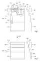
- FIG. 1 shows a schematic cross section of the layer structure or the layer sequence and the functional zones of a printing form 100 according to the invention, which from above with electromagnetic energy, preferably in the form of laser radiation 102 (e.g. Infrared radiation in the wavelength range of 830 nanometers) is applied.
- electromagnetic energy preferably in the form of laser radiation 102 (e.g. Infrared radiation in the wavelength range of 830 nanometers) is applied.
- laser radiation 102 e.g. Infrared radiation in the wavelength range of 830 nanometers
- the printing form is formed by a printing cylinder surface
- the printing cylinder itself the carrier 118th form. This also applies correspondingly in the other embodiments.
- the information layer 110 and the absorption layer 112 together form an antireflection layer 150 or an antireflection system 150 at least for the introduced radiation, ie for the corresponding wavelength, such that the radiation penetrates into the absorption layer 112 substantially without reflection.
- the layer thicknesses and the respective refractive indices are matched to one another.
- the layer thickness of the cover layer is preferably n ⁇ / 4 , where n is an odd-numbered, integer preferably greater than 5.
- the refractive index of the information layer 110 lies between the refractive index of air and the refractive index of the layer lying below the information layer 110 and is preferably the root of the refractive index of the layer located below the information layer 110.
- this buffer layer is largely transparent to the introduced radiation have to be.
- the functional zones of the printing form 100 are by lines shown. As can be seen from FIG. 1, the functional zones can be used on the one hand individual layers of the layer structure agree and on the other several Include layers (in whole or in part). It can also be seen that individual layers also can be assigned to several functional zones.
- FIG. 1 also shows the energy flow.
- the on the layer structure of the printing plate 100th radiated energy 170 in the form of electromagnetic radiation 102 is only slightly Measures lost by reflection 172 (reflection loss 172), preferably less than about 20%, so that initially only this part 172 of the incident energy 170 is not for the actual imaging process is available.
- the in the absorption zone 122nd coupled thermal energy 190 is also only slightly by transmission 174th (Transmission loss 174) lost in the carrier 118, preferably less than about 5%, In particular, 1%, and this part 174 of the radiated energy 170 is therefore also not available for the actual imaging process.
- the majority 176 (deposited heat energy 176) of the coupled-in thermal energy 190 preferably more than However, about 75%, especially 80%, is at least partially lower than the Absorbing zone 122 arranged buffer zone 124 received via heat conduction 178 and buffered as buffered thermal energy 180 in time and space. From the buffer zone 124, the heat energy 180 passes with a time delay via heat conduction 182 back into the Absorption zone 122 and the information zone 120, where the heat energy for the actual (physical or chemical) imaging process is needed.
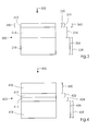
- FIG. 2 shows a schematic cross section of the layer structure or the layer sequence a further printing form 200 according to the invention, which from above with laser radiation 202, preferably in the infrared range, is applied for imaging.
- the information layer 110 and the Absorption layer 112 together an antireflection layer 250 or an antireflection system 250th at least for the introduced radiation 202, d. H. for the appropriate wavelength, like, that the radiation penetrates into the absorption layer 212 substantially without reflection.
- FIG. 3 shows a further embodiment of the invention with respect to FIG Degree of utilization of the introduced radiation 302 optimized printing form 300 with amphiphilic Shown molecules.
- a polymer film may also be a carrier made of sheet metal, preferably steel or Aluminum sheet can be used, the sheet preferably with about a 10 or only about 5 microns thick polyimide layer can be provided (eg by gluing).
- An optionally applied on the absorption layer 312, usable as an information layer and with the absorption layer 312 an antireflection layer 350 forming further layer may be exemplified as a TiO 2 layer which reduces the reflection of the incident light by destructive interference (example: refractive index of TiO 2 is 1.8, wavelength is 900 nanometers, thickness is 125 nanometers).
- titanium (Ti) its oxides or nitrides may be present in the layer 312 (or in the additional Antireflective coating) also zirconium (Zr), manganese (Mn), aluminum (Al), chromium (Cr), Tantalum (Ta), tin (Sn), zinc (Zn) and iron (Fe), their oxides or nitrides or mixtures be used.
- a very thin buffer layer 314 may be provided be further tasked, the layer interface between the polyimide film 318th and to protect their coating from excessive thermal stress.
- the scheduling of layer 312 with amphiphilic molecules happens after activation the layer 312 with ultraviolet light (Xe2, Hg or atmospheric pressure plasma) by wetting with a 1 millimolar ethanolic solution of the amphiphilic molecules, then rinsing the layer 312 with the solvent and drying with N2.
- the layer 312 is also very resistant to abrasion, resulting in stability in the printing process benefits.
- the polyimide substrate provides effective thermal insulation, so that the coupled heat energy essentially for heating a only 600 nanometers thick Area is used on the surface. This is the achievement of the Becularungstemperatur already possible with low laser power.
- FIG. 3 in addition to the layer sequence of the printing form 300, the functional zones are again shown represented by lines: an information zone 320, an absorption zone 322, a Buffer zone 324, an isolation zone 326, a carrier zone 328 and an antireflection zone 360.
- FIG. 4 shows a further embodiment of the invention for a printing forme 400, which is based on the principle of thermal mixing and during a Bericeungsreaes with laser radiation 402 applied according to the image information becomes.
- the polymer surface is inherently hydrophobic and can be treated by treatment with Chemicals, eg. B. with KMnO4 or by plasma or ultraviolet treatment over a large area be hydrophilized, wherein the penetration depth of such processes typically 10 nanometers does not exceed.
- the polymer If the polymer is then melted, then not hydrophilized, mix deeper lying molecules and hydrophilized molecules of the treated surface. After solidification of the polymer, the proportion of hydrophilized molecules on the surface is as large as their proportion in the polymer layer as a whole, d. H. at z. B. 1 nanometer Hydrophilticianstiefe and 5 microns layer thickness only 0.2 per thousand. The solidified polymer layer thus has regain their hydrophobic character.
- the previously hydrophilized printing form can thus be effectively imaged, d. H. be spotwise hydrophobic by melting and thermal mixing.
- the functional zones are again printing form 400 represented by lines: An information zone 420, a Absorbent zone 422, a buffer zone 424, an isolation zone 426 and a carrier zone 428.
- the invention can also be used in printing processes in which the printed image by Laser radiation is written in a full-surface ink layer on the printing plate.
- the first hard color layer is liquefied at the imaging points and by a given given solidification delay of the ink, the printed image on a Substrate are transferred.
- the printing form has a carrier layer (corresponding to 118 in Figure 1), an insulating layer (corresponding to 116 in Figure 1), wherein the Carrier and the insulating layer can also form a unit (corresponding to 218 in FIG 2), and a buffer layer (corresponding to 114 in FIG. 1).
- the absorption layer (corresponding to 112 in FIG. 1) and also the information layer (corresponding to 110 in FIG. 1) are formed by the applied color layer.
Landscapes
- Engineering & Computer Science (AREA)
- Manufacturing & Machinery (AREA)
- Materials For Photolithography (AREA)
- Printing Plates And Materials Therefor (AREA)
- Photosensitive Polymer And Photoresist Processing (AREA)
- Laminated Bodies (AREA)
Abstract
Description
Aus der EP 1 245 385 A2 ist bereits eine bebilderbare Nassoffset-Druckform bekannt, welche einen Schichtaufbau aufweist. Die Druckform, bzw. deren fotokatalytisch und thermisch veränderbares Material wie z. B. TiO2 wird an der Oberfläche mit Ultraviolett-Strahlung fotokatalytisch vollflächig hydrophiliert und mit Infrarot-Strahlung thermisch bildpunktweise hydrophobiert, wobei die Wärmeenergie von Absorptionszentren im veränderbaren Material oder einer Absorptionsschicht unterhalb dieses Materials aufgenommen wird.
Die Zeichnungen zeigen:
- Figur 1
- einen schematischen Querschnitt des Schichtaufbaus und der Funktionszonen einer erfindungsgemäßen Druckform;
- Figur 2
- einen schematischen Querschnitt des Schichtaufbaus und der Funktionszonen einer weiteren erfindungsgemäßen Druckform;
- Figur 3
- einen schematischen Querschnitt des Schichtaufbaus und der Funktionszonen einer weiteren erfindungsgemäßen Druckform;
- Figur 4
- einen schematischen Querschnitt des Schichtaufbaus und der Funktionszonen einer weiteren erfindungsgemäßen Druckform.
- Eine erste Schicht 110 (Deckschicht oder Informationsschicht 110) besteht aus Titandioxid (TiO2) und weist bevorzugt eine Schichtdicke von etwa 50 Nanometer auf (+/- etwa 10%). Diese Schicht 110 bildet eine äußere Schicht 110 der Druckform und trägt nach dem Bebilderungsprozess die Bildinformation vorzugsweise in Form einer Strukturierung in hydrophile und hydrophobe Bereiche. Bereits diese Schicht 110 kann die eingebrachte Strahlung zumindest teilweise absorbieren, jedoch ist die Absorptionsfähigkeit durch die geringe Schichtdicke meist nicht ausreichend;
- Eine zweite Schicht 112 (Absorptionsschicht 112) besteht aus Titan (oder Molybdän), Kohlenstoff, Stickstoff und Sauerstoff (Ti-C, N, O) und weist bevorzugt eine Schichtdicke von etwa 250 Nanometer (+/- etwa 50%) auf. In dieser Schicht, welche die Strahlung 102 vorzugsweise zu etwa 80% oder mehr absorbiert, wird die Energie der Laserstrahlung 102 stark absorbiert und in Wärmeenergie umgewandelt. Durch die große Schichtdicke im Verhältnis zur Informationsschicht 110 wird in dieser Schicht 112 eine ausreichende Absorption der eingebrachten Strahlung erzielt;
- Eine dritte Schicht 114 (Pufferschicht 114) besteht aus einer periodischen Mehrfachschicht aus Titan (oder Molybdän) und weist bevorzugt eine Schichtdicke mehr als etwa 0,5 Mikrometer und weniger als etwa 10 Mikrometer, insbesondere etwa 1 Mikrometer auf. Die Pufferschicht kann aufgrund einer bevorzugt hohen Wärmekapazität, vorzugsweise etwa 1 bis 4 Millijoule/Kelvin Zentimeter3, die in die Druckform 100 eingekoppelte Wärmeenergie in besonders ausgeprägter Weise speichern. Weiterhin kann die Wärmeenergie aufgrund einer bevorzugt hohen Wärmeleitfähigkeit der Pufferschicht 114, vorzugsweise etwa 5 bis 50 Watt/(Meter Kelvin), insbesondere etwa 10 bis 20 Watt/(Meter Kelvin), in der Pufferschicht 114 schnell transportiert und verteilt werden;
- Eine vierte Schicht 116 (Isolationsschicht 116) besteht aus Polyimid (PI) und weist bevorzugt eine Schichtdicke von mehr als etwa 10 Mikrometer, insbesondere etwa 50 Mikrometer auf. Aufgrund der niedrigen Wärmeleitfähigkeit dieser Schicht, vorzugsweise 0,1 bis 0,2 Watt/(Meter Kelvin), findet kaum Wärmetransport (bzw. Wärmeabfluss) durch die Isolationsschicht zur einer tiefer liegenden Schicht statt;
- Eine fünfte Schicht 118 (Trägerschicht oder Träger 118) besteht aus Aluminium, z. B. in Form eines Aluminiumblechs, und weist bevorzugt eine Schichtdicke von etwa 100 bis 250 Mikrometer auf. Die Trägerschicht ist mechanisch stabil und bildet für die darauf aufgebrachten Schichten 110, 112, 114 und 116 einen Träger (bzw. ein Substrat).
- Eine erste Funktionszone 120 (Bildinformation tragende oder tragfähige Zone oder Informationszone 120) ist durch thermisch induzierte oberflächenphysikalische und/oder oberflächenchemische Prozesse und/oder Beschichtungsprozesse definiert, welche einer Strukturierung der Druckform 100 in dieser Funktionszone 120 entsprechend der Bildinformation zugrunde liegen. Diese Zone ist folglich entsprechend einer Bildinformation veränderbar, in der Weise, dass die zuvor im Wesentlichen unstrukturierte Zone nach dem Bebilderungsvorgang bildentsprechend strukturiert ist;
- Eine zweite Funktionszone 122 (Absorptionszone 122) ist durch eine Absorptionsfähigkeit für die eingebrachte Strahlung 102 und eine Konversion der Strahlungsenergie in Wärmeenergie definiert, wobei vorzugsweise das Material im Bereich der Absorptionszone 122 eine Absorption von etwa 80% oder mehr für die Strahlung 102 aufweisen kann. Die optische Eindringtiefe für die eingebrachte Strahlung 102 ist vorzugsweise im Wesentlichen kleiner oder gleich als die Dicke des Absorptionszone 122.
- Eine dritte Funktionszone 124 (Pufferzone 124) ist durch eine Speicher- bzw. Pufferfähigkeit für die eingekoppelte Wärmeenergie definiert. Die Pufferzone 124 kann aufgrund einer bevorzugt hohen Wärmekapazität des im Bereich der Pufferzone 124 befindlichen Materials, vorzugsweise etwa 1 bis 4 Millijoule/Kelvin Zentimeter3, die in die Druckform 100 eingekoppelte Wärmeenergie in besonders ausgeprägter Weise speichern. Weiterhin kann die Wärmeenergie aufgrund einer bevorzugt hohen Wärmeleitfähigkeit des im Bereich der Pufferzone 124 befindlichen Materials, vorzugsweise etwa 5 bis 50 Watt/(Meter Kelvin), insbesondere etwa 10 bis 20 Watt/(Meter Kelvin), in der Pufferzone 124 schnell transportiert und verteilt werden;
- Eine vierte Funktionszone 126 (Isolationszone 126) ist durch eine Isolationsfähigkeit definiert, in der Weise, dass ein Wärmefluss von der über der Isolationszone 26 liegenden Pufferzone 124 (oder einer Zwischenzone), bzw. der zugeordneten Schicht, in die unter der Isolationszone 126 liegenden Zone, bzw. die zugeordnete Schicht, verringert oder im Wesentlichen vollständig verhindert wird. Das Material, welches zum Aufbau der Isolationszone eingesetzt wird, weist zu diesem Zweck bevorzugt eine niedrige Wärmeleitfähigkeit von vorzugsweise etwa 0,1 bis 0,2 Watt/(Meter Kelvin) auf;
- Eine fünfte Funktionszone 128 (Trägerzone 128) ist durch eine mechanische Stabilität definiert, in der Weise, dass die Trägerzone 128 (bzw. der zugeordnete Träger 118) geeignet ist, die weiteren Funktionszonen (bzw. die zugeordneten Schichten) zur Bildung einer in Richtung der Flächenausdehnung der Zonen mechanisch stabilen und bevorzugt senkrecht zur Fläche der Zonen biegsamen Einheit 100 (Druckform 100) aufzunehmen. Ein solcher Träger 118, z. B. ein metallischer Träger 118 ist insbesondere bei großformatigen Druckformen zweckdienlich. Die Trägerzone 128 weist bevorzugt eine geringe Dicke und einen hohen E-Modul auf.
- Eine weitere Funktionszone 160 (Antireflexzone 160) ist durch eine Antireflex-Fähigkeit (bzw. Transmissionsfähigkeit) für die eingebrachte Strahlung 102 definiert, so dass die Strahlung 102 weitgehend unreflektiert, bevorzugt mit einem Reflexionskoeffizient von weniger als etwa 20%, in die tiefer liegende Absorptionszone vordringt. Die Antireflex-Zone 160 umfasst die Informationszone 120 und die Absorptionszone 122. Wie in Bezug auf die Antireflexschicht 150 bereits erläutert, ist die Dicke der zugrunde liegenden Zone 120 auf die Wellenlänge der Strahlung 102 abzustimmen;
- Eine erste Schicht 210 (Deckschicht oder Informationsschicht 210) besteht aus Siliziumdioxid (SiO2) und weist bevorzugt eine Schichtdicke von etwa 50 Nanometer (+/etwa 10%) auf;
- Eine zweite Schicht 212 (Absorptionsschicht 212) besteht aus TiNxO2-x und weist bevorzugt eine Schichtdicke von etwa 250 Nanometer (+/- etwa 50%) auf;
- Eine dritte Schicht 214 (Pufferschicht 214) besteht aus metallischem Titan weist bevorzugt eine Schichtdicke von etwa 1 bis 10 Mikrometer, bevorzugt etwa 1 Mikrometer auf;
- Eine vierte Schicht 218 (Isolations- und Trägerschicht 218) besteht aus Polyimid und weist bevorzugt eine Schichtdicke von etwa 100 bis 300 Mikrometer, bevorzugt etwa 250 Mikrometer auf. In dieser Schicht 218 erfüllt das Schichtmaterial Polyimid sowohl die Trägerfunktion als auch die Isolationsfunktion.
- Eine erste Funktionszone 220 bildet die Informationszone 220;
- Eine zweie Funktionszone 222 bildet die Absorptionszone 222;
- Eine dritte Funktionszone 224 bildet die Pufferzone 224;
- Eine vierte Funktionszone 226 bildet die Isolationszone 226;
- Eine fünfte Funktionszone 228 bildet die Trägerzone 228.
- Eine weitere Funktionszone 260 bildet die Antireflexzone 222;
- Eine etwa 100 bis 500 Nanometer dicke erste Schicht 312 (Absorptionsschicht 312) aus Titan, Kohlenstoff, Stickstoff und Sauerstoff (Ti-C, N, O). Es können aber auch andere Materialien bzw. Materialsysteme eingesetzt werden, die eine geringe optische Eindringtiefe aufweisen. Das verwendete Material sollte entweder zumindest an der Oberfläche den Bebilderungs-Prozessanforderungen genügen (in diesem Fall ist die Absorptionsschicht zumindest an ihrer Außenseite zugleich die Deck- oder Informationsschicht) oder aber mit einer weiteren, äußeren Schicht versehen werden (in diesem Fall existiert eine separate Deck- oder Informationsschicht), die diesen Anforderungen genügt, beispielsweise TiO2. Die Schicht 312 weist für die Strahlung 302 einen Reflexionsgrad von vorzugsweise weniger als etwa 20% auf, d. h. die Absorptionsschicht 312 kann gleichzeitig eine Antireflex-Funktion erfüllen bzw. eine Antireflexschicht bilden;
- Eine etwa 0,3 bis 10 Mikrometer, bevorzugt 0,5 bis 2 Mikrometer dicke zweite Schicht 314 (Pufferschicht 314) aus Edelstahl. Anstelle von Edelstahl kann auch ein anderes Material mit im Vergleich zu einem Polymer guter Wärmeleitfähigkeit gewählt werden, wobei die Wärmeabsorption pro Flächeneinheit und Grad Kelvin (J/(m2K)) in etwa derjenigen von 500 Nanometer Edelstahl entsprechen sollte. Ferner kann auch ein periodischer Schichtstapel zweier oder mehrerer Materialen, vorzugsweise Metalle (z. B. Molybdän und/oder Titan) vorgesehen sein;
- Eine etwa 100 bis 300 Mikrometer dicke Trägersicht 318 aus Polyimid-Folie (bzw. Kapton®), welche neben der Trägerfunktion auch die thermische Isolationsfunktion erfüllt, d. h. die Trägerschicht 318 bildet zugleich die Isolationsschicht. Neben Polyimid sind auch andere Polymere denkbar, die den besonderen thermischen, chemischen und mechanischen Einflüssen und Belastungen während der Bebilderung oder des Druckens standhalten.
- Eine etwa 1 bis 10 Mikrometer dicke Informationsschicht 410 eines schmelzbaren und chemisch hydrophilierbaren Polymers, welches thermisch durchmischt werden kann;
- Eine etwa 100 bis 500 Nanometer dicke Absorptionsschicht 412 aus Titan, Kohlenstoff, Stickstoff und Sauerstoff (Ti-C, N, O) oder Chrom, Kohlenstoff, Stickstoff und Sauerstoff (Cr-C, N, O).
- Eine etwa 2 bis 5 Mikrometer dicke Pufferschicht 414 aus Molybdän. Anstelle von Molybdän kann auch ein anderes Material mit im Vergleich zu einem Polymer guter Wärmeleitfähigkeit gewählt werden, wobei die Wärmeabsorption pro Flächeneinheit und Grad Kelvin (J/(m2K)) in etwa derjenigen von 2 Mikrometer Molybdän entsprechen sollte. Ferner kann auch ein periodischer Schichtstapel zweier oder mehrerer Materialen, vorzugsweise Metalle (z. B. Molybdän und/oder Titan) vorgesehen sein;
- Eine etwa 100 bis 300 Mikrometer dicke Trägersicht 418 aus Polyimid-Folie (bzw. Kapton®), welche neben der Trägerfunktion auch die thermische Isolationsfunktion erfüllt. Alternativen zur Polyimid-Folie sind entsprechend dem Ausführungsbeispiel zur Figur 3 möglich.
- Deck- oder Informationszone: hohe Abrasionsbeständigkeit und gute thermisch induzierte Strukturierbarkeit entsprechend der zu erzeugenden Bildinformation;
- Absorptionszone: hohe Absorptionsfähigkeit, d. h. geringe optische Eindringtiefe, zumindest für die eingestrahlte Bebilderungswellenlänge, bedingt durch eine hohe Konzentration von Absorptionszentren zumindest nahe der Oberfläche, z. B. in einem Bereich von weniger als etwa 200 Nanometer Tiefe;
- Pufferzone bzw. angepasste Pufferzone: hohe Wärmekapazität und Wärmeleitfähigkeit; vorzugsweise große Dicke im Vergleich zur Absorptionszone;
- Isolationszone: geringe Wärmeleitfähigkeit und/oder geringe Wärmekapazität im Vergleich zur Pufferzone;
- Trägerzone: ausreichende mechanische Stabilität, hoher E-Modul;
- Antireflexzone: geringe Reflexion zumindest für die Bebilderungswellenlänge.
- 100
- Druckform
- 102
- Laserstrahlung
- 110
- Deckschicht/Informations schicht
- 112
- Absorptionsschicht
- 114
- Pufferschicht
- 116
- Isolationsschicht
- 118
- Trägerschicht/Träger/Zylinder
- 120
- Informationszone
- 122
- Absorptionszone
- 124
- Pufferzone
- 126
- Isolationszone
- 128
- Trägerzone
- 150
- Antireflexschicht/Antireflexsystem
- 160
- Antireflexzone
- 170
- eingestrahlte Energie
- 172
- Reflexionsverlust
- 174
- Transmissionsverlust
- 176
- deponierte Wärmeenergie
- 178
- Wärmeleitung
- 180
- gepufferte Wärmeenergie
- 182
- Wärmeleitung
- 190
- eingekoppelte Wärmeenergie
- 200
- Druckform
- 202
- Laserstrahlung
- 210
- Informationsschicht
- 212
- Absorptionsschicht
- 214
- Pufferschicht
- 218
- Isolations- und Trägerschicht/Träger
- 220
- Informationszone
- 222
- Absorptionszone
- 224
- Pufferzone
- 226
- Isolationszone
- 228
- Trägerzone
- 250
- Antireflexschicht/Antireflexsystem
- 260
- Antireflexzone
- 300
- Druckform
- 302
- Laserstrahlung
- 312
- Absorptionsschicht
- 314
- Pufferschicht
- 318
- Trägerschicht/Träger
- 320
- Informationszone
- 322
- Absorptionszone
- 324
- Pufferzone
- 326
- Isolationszone
- 328
- Trägerzone
- 350
- Antireflexschicht/Antireflexsystem
- 360
- Antireflexzone
- 400
- Druckform
- 402
- Laserstrahlung
- 410
- Informationsschicht
- 412
- Absorptionsschicht
- 414
- Pufferschicht
- 418
- Trägerschicht/Träger
- 420
- Informationszone
- 422
- Absorptionszone
- 424
- Pufferzone
- 426
- Isolationszone
- 428
- Trägerzone
Claims (12)
- Druckform mit mehreren flächigen Funktionszonen, welche zumindest eine entsprechend einer Bildinformation veränderbare Informationszone (110, 210, 312, 410) und eine Absorptionszone (112, 212, 312, 412) für Energie einer Strahlung (102, 202, 302, 402) aufweist,
dadurch gekennzeichnet, dass eine zumindest teilweise von der Absorptionszone (112, 212, 312, 412) verschiedene Pufferzone (114, 214, 314, 414) vorgesehen ist, welche Energie von der Absorptionszone (112, 212, 312, 412) aufnimmt und Energie an die Informationszone (110, 210, 312, 410) abgibt. - Druckform nach Anspruch 1,
dadurch gekennzeichnet, dass die Pufferzone (114, 214, 314, 414) zumindest teilweise unterhalb der Absorptionszone (112, 212, 312, 412) vorgesehen ist. - Druckform nach einem der vorhergehenden Ansprüche,
dadurch gekennzeichnet, dass die Pufferzone (114, 214, 314, 414) als angepasste Pufferzone ausgebildet ist. - Druckform nach einem der vorhergehenden Ansprüche,
dadurch gekennzeichnet, dass die Pufferzone (114, 214, 314, 414) dicker als die Absorptionszone (112, 212, 312, 412) ausgebildet ist, insbesondere eine Dicke von etwa 0,5 bis 10 Mikrometer oder eine Dicke von etwa 1 Mikrometer aufweist. - Druckform nach einem der vorhergehenden Ansprüche,
dadurch gekennzeichnet, dass die entsprechend einer Bildinformation veränderbare Informationszone (110, 210, 312, 410) als eine äußere Bildinformation tragende oder tragfähige Zone (110, 210, 312, 410) ausgebildet ist. - Druckform nach einem der vorhergehenden Ansprüche 1 bis 4,
dadurch gekennzeichnet, dass die entsprechend einer Bildinformation veränderbare Informationszone (110, 210, 312, 410) als eine äußere Bildinformation tragende oder tragfähige Farbschicht (312) oder Polymerschicht (410) ausgebildet ist. - Druckform nach einem der vorhergehenden Ansprüche,
dadurch gekennzeichnet, dass eine Antireflex-Zone (160, 260, 360) für die Strahlung (102, 202, 302) vorgesehen ist. - Druckform nach Anspruch 7,
dadurch gekennzeichnet, dass die Antireflex-Zone (160, 260, 360) von der entsprechend einer Bildinformation veränderbaren Informationszone (110, 210, 312, 410) und der Absorptionszone (112, 212, 312, 412) gebildet ist. - Druckform nach einem der vorhergehenden Ansprüche,
dadurch gekennzeichnet, dass eine thermische Isolationszone (116, 218, 318, 418) zumindest teilweise unterhalb der Pufferzone (114, 214, 314, 414) vorgesehen ist. - Druckform nach einem der vorhergehenden Ansprüche,
dadurch gekennzeichnet, dass die Druckform (100, 200, 300, 400) einen Träger (118, 218, 318, 418) aufweist. - Druckform nach einem der vorhergehenden Ansprüche,
dadurch gekennzeichnet, dass zumindest die Absorptionszone (112, 212, 312, 412) und die Pufferzone (114, 214, 314, 414) als separate Schichten ausgebildet sind. - Druckmaschine mit wenigstens einem Druckzylinder,
dadurch gekennzeichnet, dass der Druckzylinder (118) mit einer Druckform (100, 200, 300, 400) nach einem der vorhergehenden Ansprüche versehen ist oder dass der Druckzylinder (118) eine Druckform (100, 200, 300, 400) nach einem der vorhergehenden Ansprüche bildet.
Applications Claiming Priority (2)
| Application Number | Priority Date | Filing Date | Title |
|---|---|---|---|
| DE102004007600A DE102004007600A1 (de) | 2004-02-17 | 2004-02-17 | Druckform mit mehreren flächigen Funktionszonen |
| DE102004007600 | 2004-02-17 |
Publications (3)
| Publication Number | Publication Date |
|---|---|
| EP1563992A2 true EP1563992A2 (de) | 2005-08-17 |
| EP1563992A3 EP1563992A3 (de) | 2006-01-11 |
| EP1563992B1 EP1563992B1 (de) | 2016-09-07 |
Family
ID=34684082
Family Applications (1)
| Application Number | Title | Priority Date | Filing Date |
|---|---|---|---|
| EP05100599.9A Expired - Lifetime EP1563992B1 (de) | 2004-02-17 | 2005-01-31 | Druckform mit mehreren flächigen Funktionszonen |
Country Status (7)
| Country | Link |
|---|---|
| US (1) | US7704590B2 (de) |
| EP (1) | EP1563992B1 (de) |
| JP (1) | JP4904003B2 (de) |
| CN (1) | CN100500450C (de) |
| CA (1) | CA2496342A1 (de) |
| DE (1) | DE102004007600A1 (de) |
| IL (1) | IL166910A (de) |
Families Citing this family (11)
| Publication number | Priority date | Publication date | Assignee | Title |
|---|---|---|---|---|
| US8733248B2 (en) | 2006-02-21 | 2014-05-27 | R.R. Donnelley & Sons Company | Method and apparatus for transferring a principal substance and printing system |
| US8869698B2 (en) | 2007-02-21 | 2014-10-28 | R.R. Donnelley & Sons Company | Method and apparatus for transferring a principal substance |
| KR101316680B1 (ko) | 2006-02-21 | 2013-10-10 | 무어 월리스 노스 아메리카, 인코포레이티드 | 고속 변동인쇄용 시스템 및 방법 |
| US8967044B2 (en) | 2006-02-21 | 2015-03-03 | R.R. Donnelley & Sons, Inc. | Apparatus for applying gating agents to a substrate and image generation kit |
| US9463643B2 (en) | 2006-02-21 | 2016-10-11 | R.R. Donnelley & Sons Company | Apparatus and methods for controlling application of a substance to a substrate |
| US9701120B2 (en) | 2007-08-20 | 2017-07-11 | R.R. Donnelley & Sons Company | Compositions compatible with jet printing and methods therefor |
| MX2010001992A (es) | 2007-08-20 | 2010-08-31 | Moore Wallace North Am Inc | Aparato y metodos para controlar la aplicacion de una sustancia en un substrato. |
| DE102012013302A1 (de) | 2011-08-11 | 2013-02-14 | Heidelberger Druckmaschinen Ag | Druckform |
| DE102012021983A1 (de) | 2012-06-15 | 2013-12-19 | Heidelberger Druckmaschinen Ag | Verfahren zum indirekten Auftragen von Druckflüssigkeit auf einen Bedruckstoff |
| US10153324B2 (en) * | 2016-09-02 | 2018-12-11 | Arizona Board Of Regents On Behalf Of Arizona State University | Low-voltage charge-coupled devices with a heterostructure charge-storage well |
| CN110588141A (zh) * | 2019-09-03 | 2019-12-20 | 天津保创印刷材料有限公司 | 印刷版及其制备工艺 |
Family Cites Families (17)
| Publication number | Priority date | Publication date | Assignee | Title |
|---|---|---|---|---|
| US5322763A (en) * | 1992-05-06 | 1994-06-21 | E. I. Du Pont De Nemours And Company | Process for making metal ledge on stencil screen |
| US5351617A (en) * | 1992-07-20 | 1994-10-04 | Presstek, Inc. | Method for laser-discharge imaging a printing plate |
| USRE35512F1 (en) * | 1992-07-20 | 1998-08-04 | Presstek Inc | Lithographic printing members for use with laser-discharge imaging |
| US5570636A (en) * | 1995-05-04 | 1996-11-05 | Presstek, Inc. | Laser-imageable lithographic printing members with dimensionally stable base supports |
| US5868074A (en) * | 1995-05-08 | 1999-02-09 | Flex Products, Inc. | Laser imageable direct-write printing member |
| US5632204A (en) * | 1995-07-27 | 1997-05-27 | Presstek, Inc. | Thin-metal lithographic printing members with integral reflective layers |
| US5783364A (en) * | 1996-08-20 | 1998-07-21 | Presstek, Inc. | Thin-film imaging recording constructions incorporating metallic inorganic layers and optical interference structures |
| EP0847853B1 (de) * | 1996-11-14 | 2001-01-24 | Kodak Polychrome Graphics LLC | Entwicklungsfreie Flachdruckplatte |
| EP1860499B1 (de) * | 1997-11-03 | 2015-02-11 | SPGPrints B.V. | Verfahren zum Herstellen einer Druckform |
| US6073559A (en) * | 1998-09-11 | 2000-06-13 | Presstek, Inc. | Lithographic imaging with constructions having inorganic oleophilic layers |
| DE10138772A1 (de) | 2000-09-07 | 2002-03-28 | Heidelberger Druckmasch Ag | Wiederbeschreibbare Druckform zum Drucken mit schmelzbarer Druckfarbe |
| JP2002082429A (ja) * | 2000-09-08 | 2002-03-22 | Fuji Photo Film Co Ltd | ネガ型画像記録材料 |
| US6521391B1 (en) * | 2000-09-14 | 2003-02-18 | Alcoa Inc. | Printing plate |
| DE10115435B8 (de) * | 2001-03-29 | 2007-02-08 | Maschinenfabrik Wifag | Verfahren zur Erzeugung eines Druckbilds und/oder zur Löschung eines Druckbilds einer Nassoffset-Druckform mit fotothermisch veränderbarem Material |
| DE10227054B4 (de) | 2002-06-17 | 2013-01-03 | Heidelberger Druckmaschinen Ag | Wiederverwendbare Druckform, Druckwerk und Druckmaschine damit sowie Verfahren zur Bebilderung der Druckform |
| DE10354341A1 (de) | 2002-11-21 | 2004-06-03 | Heidelberger Druckmaschinen Ag | Verfahren und Einrichtung zum Strukturieren einer Druckformoberfläche |
| AU2005231729A1 (en) * | 2004-03-26 | 2005-10-20 | Presstek, Inc. | Printing members having solubility-transition layers and related methods |
-
2004
- 2004-02-17 DE DE102004007600A patent/DE102004007600A1/de not_active Ceased
-
2005
- 2005-01-31 EP EP05100599.9A patent/EP1563992B1/de not_active Expired - Lifetime
- 2005-02-09 CA CA002496342A patent/CA2496342A1/en not_active Abandoned
- 2005-02-15 IL IL166910A patent/IL166910A/en not_active IP Right Cessation
- 2005-02-15 US US11/058,039 patent/US7704590B2/en not_active Expired - Fee Related
- 2005-02-17 JP JP2005041071A patent/JP4904003B2/ja not_active Expired - Fee Related
- 2005-02-17 CN CNB2005100090668A patent/CN100500450C/zh not_active Expired - Fee Related
Also Published As
| Publication number | Publication date |
|---|---|
| JP4904003B2 (ja) | 2012-03-28 |
| IL166910A (en) | 2007-06-17 |
| US7704590B2 (en) | 2010-04-27 |
| JP2005231370A (ja) | 2005-09-02 |
| CN100500450C (zh) | 2009-06-17 |
| CN1657313A (zh) | 2005-08-24 |
| DE102004007600A1 (de) | 2005-09-01 |
| CA2496342A1 (en) | 2005-08-17 |
| EP1563992A3 (de) | 2006-01-11 |
| US20050181187A1 (en) | 2005-08-18 |
| EP1563992B1 (de) | 2016-09-07 |
Similar Documents
| Publication | Publication Date | Title |
|---|---|---|
| DE69733906T2 (de) | Dünnfilm-Bildaufzeichnungskonstruktionen mit anorganischen Metallschichten und optischen Interferenz-Strukturen | |
| DE2747433C2 (de) | ||
| DE69514568T2 (de) | Flachdruckplatten zur Bebilderung mittels Laserbestrahlung | |
| EP1563992B1 (de) | Druckform mit mehreren flächigen Funktionszonen | |
| DE69914649T2 (de) | Verfahren zur lithographischen Aufzeichnung mit weniger Leistungsfähigkeitsverschlechterung durch Abstoffe | |
| EP2711196B1 (de) | Verfahren zur Herstellung eines Mehrschichtkörpers mit diffraktiver Reliefstruktur | |
| DE3636129C2 (de) | ||
| DE69914956T2 (de) | Thermotransfer einer russ enthaltenden schwarzen matrix | |
| EP2191976B1 (de) | Verfahren zum Markieren oder Beschriften eines Werkstücks | |
| EP0559069A1 (de) | Wertdokument | |
| DE2514678B2 (de) | Metallfilm-aufzeichnungsmedium | |
| DE69731969T2 (de) | Flachdruckplatten-vorlaüfer mit einer mit laserbestrahlung bebildbarer mehrschichtfolie mit optischen hohlraum | |
| EP1151857A2 (de) | Gesteuerte Bebilderung und Löschung einer Druckform aus metallischem Titan | |
| DE10360108A1 (de) | Herstellung einer wiederverwendbaren Druckform | |
| EP1036655A1 (de) | Bebilderung einer Druckform für einen Nassoffsetdruck | |
| DE69926211T2 (de) | Flachdruckplatte und Verfahren zu seiner Herstellung, das Laserstrahlung verwendet | |
| DE69917126T2 (de) | Vorläufer für eine Flachdruckplatte sowie Verfahren zu deren Herstellung | |
| DE10115435A1 (de) | Nassoffset-Druckform mit fotothermisch veränderbarem Material und Verfahren und Vorrichtung zur Erzeugung eines Druckbilds und/oder zur Löschung eines Druckbilds einer Nassoffset-Druckform | |
| DE69907580T2 (de) | Verfahren zur lithographischen Aufzeichnung mit weniger Leistungsfähigkeitsverschlechterung durch Abstoffe | |
| WO2008092650A2 (de) | Verfahren und prägefolie zum selektiven übertragen mindestens einer funktionsschicht auf ein substrat | |
| EP1458654B1 (de) | Verfahren zur erzeugung lokal funktioneller photokatalytischer bereiche und damit erhältliche gegenstände | |
| DE60113898T2 (de) | Verfahren zur ausbildung eines ablationsbildes | |
| DE10017614B4 (de) | Verfahren zur Herstellung einer dielektrischen Reflexionsmaske | |
| DE102012013302A1 (de) | Druckform | |
| DE10138772A1 (de) | Wiederbeschreibbare Druckform zum Drucken mit schmelzbarer Druckfarbe |
Legal Events
| Date | Code | Title | Description |
|---|---|---|---|
| PUAI | Public reference made under article 153(3) epc to a published international application that has entered the european phase |
Free format text: ORIGINAL CODE: 0009012 |
|
| AK | Designated contracting states |
Kind code of ref document: A2 Designated state(s): AT BE BG CH CY CZ DE DK EE ES FI FR GB GR HU IE IS IT LI LT LU MC NL PL PT RO SE SI SK TR |
|
| AX | Request for extension of the european patent |
Extension state: AL BA HR LV MK YU |
|
| PUAL | Search report despatched |
Free format text: ORIGINAL CODE: 0009013 |
|
| AK | Designated contracting states |
Kind code of ref document: A3 Designated state(s): AT BE BG CH CY CZ DE DK EE ES FI FR GB GR HU IE IS IT LI LT LU MC NL PL PT RO SE SI SK TR |
|
| AX | Request for extension of the european patent |
Extension state: AL BA HR LV MK YU |
|
| RIC1 | Information provided on ipc code assigned before grant |
Ipc: B41N 1/08 20060101ALI20051121BHEP Ipc: B41N 1/14 20060101ALI20051121BHEP Ipc: B41C 1/10 20060101AFI20050602BHEP |
|
| 17P | Request for examination filed |
Effective date: 20060711 |
|
| AKX | Designation fees paid |
Designated state(s): AT BE BG CH CY CZ DE DK EE ES FI FR GB GR HU IE IS IT LI LT LU MC NL PL PT RO SE SI SK TR |
|
| 17Q | First examination report despatched |
Effective date: 20061009 |
|
| APBK | Appeal reference recorded |
Free format text: ORIGINAL CODE: EPIDOSNREFNE |
|
| APBN | Date of receipt of notice of appeal recorded |
Free format text: ORIGINAL CODE: EPIDOSNNOA2E |
|
| APBR | Date of receipt of statement of grounds of appeal recorded |
Free format text: ORIGINAL CODE: EPIDOSNNOA3E |
|
| APAF | Appeal reference modified |
Free format text: ORIGINAL CODE: EPIDOSCREFNE |
|
| APBX | Invitation to file observations in appeal sent |
Free format text: ORIGINAL CODE: EPIDOSNOBA2E |
|
| APBZ | Receipt of observations in appeal recorded |
Free format text: ORIGINAL CODE: EPIDOSNOBA4E |
|
| APBT | Appeal procedure closed |
Free format text: ORIGINAL CODE: EPIDOSNNOA9E |
|
| GRAP | Despatch of communication of intention to grant a patent |
Free format text: ORIGINAL CODE: EPIDOSNIGR1 |
|
| INTG | Intention to grant announced |
Effective date: 20160601 |
|
| GRAS | Grant fee paid |
Free format text: ORIGINAL CODE: EPIDOSNIGR3 |
|
| GRAA | (expected) grant |
Free format text: ORIGINAL CODE: 0009210 |
|
| AK | Designated contracting states |
Kind code of ref document: B1 Designated state(s): AT BE BG CH CY CZ DE DK EE ES FI FR GB GR HU IE IS IT LI LT LU MC NL PL PT RO SE SI SK TR |
|
| REG | Reference to a national code |
Ref country code: GB Ref legal event code: FG4D Free format text: NOT ENGLISH |
|
| REG | Reference to a national code |
Ref country code: CH Ref legal event code: EP |
|
| REG | Reference to a national code |
Ref country code: IE Ref legal event code: FG4D Free format text: LANGUAGE OF EP DOCUMENT: GERMAN |
|
| REG | Reference to a national code |
Ref country code: AT Ref legal event code: REF Ref document number: 826469 Country of ref document: AT Kind code of ref document: T Effective date: 20161015 |
|
| REG | Reference to a national code |
Ref country code: DE Ref legal event code: R096 Ref document number: 502005015356 Country of ref document: DE |
|
| REG | Reference to a national code |
Ref country code: LT Ref legal event code: MG4D |
|
| REG | Reference to a national code |
Ref country code: NL Ref legal event code: MP Effective date: 20160907 |
|
| PG25 | Lapsed in a contracting state [announced via postgrant information from national office to epo] |
Ref country code: LT Free format text: LAPSE BECAUSE OF FAILURE TO SUBMIT A TRANSLATION OF THE DESCRIPTION OR TO PAY THE FEE WITHIN THE PRESCRIBED TIME-LIMIT Effective date: 20160907 Ref country code: FI Free format text: LAPSE BECAUSE OF FAILURE TO SUBMIT A TRANSLATION OF THE DESCRIPTION OR TO PAY THE FEE WITHIN THE PRESCRIBED TIME-LIMIT Effective date: 20160907 |
|
| PG25 | Lapsed in a contracting state [announced via postgrant information from national office to epo] |
Ref country code: NL Free format text: LAPSE BECAUSE OF FAILURE TO SUBMIT A TRANSLATION OF THE DESCRIPTION OR TO PAY THE FEE WITHIN THE PRESCRIBED TIME-LIMIT Effective date: 20160907 Ref country code: SE Free format text: LAPSE BECAUSE OF FAILURE TO SUBMIT A TRANSLATION OF THE DESCRIPTION OR TO PAY THE FEE WITHIN THE PRESCRIBED TIME-LIMIT Effective date: 20160907 Ref country code: GR Free format text: LAPSE BECAUSE OF FAILURE TO SUBMIT A TRANSLATION OF THE DESCRIPTION OR TO PAY THE FEE WITHIN THE PRESCRIBED TIME-LIMIT Effective date: 20161208 Ref country code: ES Free format text: LAPSE BECAUSE OF FAILURE TO SUBMIT A TRANSLATION OF THE DESCRIPTION OR TO PAY THE FEE WITHIN THE PRESCRIBED TIME-LIMIT Effective date: 20160907 |
|
| PG25 | Lapsed in a contracting state [announced via postgrant information from national office to epo] |
Ref country code: RO Free format text: LAPSE BECAUSE OF FAILURE TO SUBMIT A TRANSLATION OF THE DESCRIPTION OR TO PAY THE FEE WITHIN THE PRESCRIBED TIME-LIMIT Effective date: 20160907 Ref country code: EE Free format text: LAPSE BECAUSE OF FAILURE TO SUBMIT A TRANSLATION OF THE DESCRIPTION OR TO PAY THE FEE WITHIN THE PRESCRIBED TIME-LIMIT Effective date: 20160907 |
|
| PG25 | Lapsed in a contracting state [announced via postgrant information from national office to epo] |
Ref country code: PL Free format text: LAPSE BECAUSE OF FAILURE TO SUBMIT A TRANSLATION OF THE DESCRIPTION OR TO PAY THE FEE WITHIN THE PRESCRIBED TIME-LIMIT Effective date: 20160907 Ref country code: BG Free format text: LAPSE BECAUSE OF FAILURE TO SUBMIT A TRANSLATION OF THE DESCRIPTION OR TO PAY THE FEE WITHIN THE PRESCRIBED TIME-LIMIT Effective date: 20161207 Ref country code: IS Free format text: LAPSE BECAUSE OF FAILURE TO SUBMIT A TRANSLATION OF THE DESCRIPTION OR TO PAY THE FEE WITHIN THE PRESCRIBED TIME-LIMIT Effective date: 20170107 Ref country code: BE Free format text: LAPSE BECAUSE OF NON-PAYMENT OF DUE FEES Effective date: 20170131 Ref country code: PT Free format text: LAPSE BECAUSE OF FAILURE TO SUBMIT A TRANSLATION OF THE DESCRIPTION OR TO PAY THE FEE WITHIN THE PRESCRIBED TIME-LIMIT Effective date: 20170109 Ref country code: SK Free format text: LAPSE BECAUSE OF FAILURE TO SUBMIT A TRANSLATION OF THE DESCRIPTION OR TO PAY THE FEE WITHIN THE PRESCRIBED TIME-LIMIT Effective date: 20160907 Ref country code: CZ Free format text: LAPSE BECAUSE OF FAILURE TO SUBMIT A TRANSLATION OF THE DESCRIPTION OR TO PAY THE FEE WITHIN THE PRESCRIBED TIME-LIMIT Effective date: 20160907 |
|
| REG | Reference to a national code |
Ref country code: DE Ref legal event code: R097 Ref document number: 502005015356 Country of ref document: DE |
|
| PG25 | Lapsed in a contracting state [announced via postgrant information from national office to epo] |
Ref country code: IT Free format text: LAPSE BECAUSE OF FAILURE TO SUBMIT A TRANSLATION OF THE DESCRIPTION OR TO PAY THE FEE WITHIN THE PRESCRIBED TIME-LIMIT Effective date: 20160907 |
|
| PLBE | No opposition filed within time limit |
Free format text: ORIGINAL CODE: 0009261 |
|
| STAA | Information on the status of an ep patent application or granted ep patent |
Free format text: STATUS: NO OPPOSITION FILED WITHIN TIME LIMIT |
|
| PG25 | Lapsed in a contracting state [announced via postgrant information from national office to epo] |
Ref country code: DK Free format text: LAPSE BECAUSE OF FAILURE TO SUBMIT A TRANSLATION OF THE DESCRIPTION OR TO PAY THE FEE WITHIN THE PRESCRIBED TIME-LIMIT Effective date: 20160907 |
|
| 26N | No opposition filed |
Effective date: 20170608 |
|
| PG25 | Lapsed in a contracting state [announced via postgrant information from national office to epo] |
Ref country code: SI Free format text: LAPSE BECAUSE OF FAILURE TO SUBMIT A TRANSLATION OF THE DESCRIPTION OR TO PAY THE FEE WITHIN THE PRESCRIBED TIME-LIMIT Effective date: 20160907 |
|
| REG | Reference to a national code |
Ref country code: CH Ref legal event code: PL |
|
| GBPC | Gb: european patent ceased through non-payment of renewal fee |
Effective date: 20170131 |
|
| PG25 | Lapsed in a contracting state [announced via postgrant information from national office to epo] |
Ref country code: MC Free format text: LAPSE BECAUSE OF FAILURE TO SUBMIT A TRANSLATION OF THE DESCRIPTION OR TO PAY THE FEE WITHIN THE PRESCRIBED TIME-LIMIT Effective date: 20160907 |
|
| REG | Reference to a national code |
Ref country code: FR Ref legal event code: ST Effective date: 20170929 |
|
| PG25 | Lapsed in a contracting state [announced via postgrant information from national office to epo] |
Ref country code: LI Free format text: LAPSE BECAUSE OF NON-PAYMENT OF DUE FEES Effective date: 20170131 Ref country code: CH Free format text: LAPSE BECAUSE OF NON-PAYMENT OF DUE FEES Effective date: 20170131 Ref country code: FR Free format text: LAPSE BECAUSE OF NON-PAYMENT OF DUE FEES Effective date: 20170131 |
|
| REG | Reference to a national code |
Ref country code: IE Ref legal event code: MM4A |
|
| PG25 | Lapsed in a contracting state [announced via postgrant information from national office to epo] |
Ref country code: GB Free format text: LAPSE BECAUSE OF NON-PAYMENT OF DUE FEES Effective date: 20170131 Ref country code: LU Free format text: LAPSE BECAUSE OF NON-PAYMENT OF DUE FEES Effective date: 20170131 |
|
| REG | Reference to a national code |
Ref country code: BE Ref legal event code: MM Effective date: 20170131 |
|
| PG25 | Lapsed in a contracting state [announced via postgrant information from national office to epo] |
Ref country code: IE Free format text: LAPSE BECAUSE OF NON-PAYMENT OF DUE FEES Effective date: 20170131 |
|
| REG | Reference to a national code |
Ref country code: AT Ref legal event code: MM01 Ref document number: 826469 Country of ref document: AT Kind code of ref document: T Effective date: 20170131 |
|
| PG25 | Lapsed in a contracting state [announced via postgrant information from national office to epo] |
Ref country code: AT Free format text: LAPSE BECAUSE OF NON-PAYMENT OF DUE FEES Effective date: 20170131 |
|
| PG25 | Lapsed in a contracting state [announced via postgrant information from national office to epo] |
Ref country code: HU Free format text: LAPSE BECAUSE OF FAILURE TO SUBMIT A TRANSLATION OF THE DESCRIPTION OR TO PAY THE FEE WITHIN THE PRESCRIBED TIME-LIMIT; INVALID AB INITIO Effective date: 20050131 |
|
| PG25 | Lapsed in a contracting state [announced via postgrant information from national office to epo] |
Ref country code: CY Free format text: LAPSE BECAUSE OF NON-PAYMENT OF DUE FEES Effective date: 20160907 |
|
| PG25 | Lapsed in a contracting state [announced via postgrant information from national office to epo] |
Ref country code: TR Free format text: LAPSE BECAUSE OF FAILURE TO SUBMIT A TRANSLATION OF THE DESCRIPTION OR TO PAY THE FEE WITHIN THE PRESCRIBED TIME-LIMIT Effective date: 20160907 |
|
| PGFP | Annual fee paid to national office [announced via postgrant information from national office to epo] |
Ref country code: DE Payment date: 20200131 Year of fee payment: 16 |
|
| REG | Reference to a national code |
Ref country code: DE Ref legal event code: R119 Ref document number: 502005015356 Country of ref document: DE |
|
| PG25 | Lapsed in a contracting state [announced via postgrant information from national office to epo] |
Ref country code: DE Free format text: LAPSE BECAUSE OF NON-PAYMENT OF DUE FEES Effective date: 20210803 |