EP1562733B1 - Mould assembly with closure mechanism - Google Patents
Mould assembly with closure mechanism Download PDFInfo
- Publication number
- EP1562733B1 EP1562733B1 EP03770926A EP03770926A EP1562733B1 EP 1562733 B1 EP1562733 B1 EP 1562733B1 EP 03770926 A EP03770926 A EP 03770926A EP 03770926 A EP03770926 A EP 03770926A EP 1562733 B1 EP1562733 B1 EP 1562733B1
- Authority
- EP
- European Patent Office
- Prior art keywords
- mould
- guide rods
- mould part
- closed position
- parts
- Prior art date
- Legal status (The legal status is an assumption and is not a legal conclusion. Google has not performed a legal analysis and makes no representation as to the accuracy of the status listed.)
- Expired - Lifetime
Links
- 238000006073 displacement reaction Methods 0.000 claims abstract description 6
- 238000000465 moulding Methods 0.000 claims abstract description 3
- 229920002430 Fibre-reinforced plastic Polymers 0.000 claims abstract 2
- 239000011151 fibre-reinforced plastic Substances 0.000 claims abstract 2
- 238000000034 method Methods 0.000 claims description 9
- 230000000694 effects Effects 0.000 description 3
- 239000000835 fiber Substances 0.000 description 3
- 239000003292 glue Substances 0.000 description 3
- 206010061274 Malocclusion Diseases 0.000 description 2
- 208000006650 Overbite Diseases 0.000 description 2
- 239000000853 adhesive Substances 0.000 description 2
- 230000001070 adhesive effect Effects 0.000 description 2
- 229920000642 polymer Polymers 0.000 description 2
- 238000004026 adhesive bonding Methods 0.000 description 1
- 230000005489 elastic deformation Effects 0.000 description 1
- 239000012530 fluid Substances 0.000 description 1
- 239000000463 material Substances 0.000 description 1
- 238000009755 vacuum infusion Methods 0.000 description 1
Images

Classifications
-
- B—PERFORMING OPERATIONS; TRANSPORTING
- B29—WORKING OF PLASTICS; WORKING OF SUBSTANCES IN A PLASTIC STATE IN GENERAL
- B29C—SHAPING OR JOINING OF PLASTICS; SHAPING OF MATERIAL IN A PLASTIC STATE, NOT OTHERWISE PROVIDED FOR; AFTER-TREATMENT OF THE SHAPED PRODUCTS, e.g. REPAIRING
- B29C69/00—Combinations of shaping techniques not provided for in a single one of main groups B29C39/00 - B29C67/00, e.g. associations of moulding and joining techniques; Apparatus therefore
- B29C69/004—Combinations of shaping techniques not provided for in a single one of main groups B29C39/00 - B29C67/00, e.g. associations of moulding and joining techniques; Apparatus therefore making articles by joining parts moulded in separate cavities, said parts being in said separate cavities during said joining
-
- B—PERFORMING OPERATIONS; TRANSPORTING
- B29—WORKING OF PLASTICS; WORKING OF SUBSTANCES IN A PLASTIC STATE IN GENERAL
- B29C—SHAPING OR JOINING OF PLASTICS; SHAPING OF MATERIAL IN A PLASTIC STATE, NOT OTHERWISE PROVIDED FOR; AFTER-TREATMENT OF THE SHAPED PRODUCTS, e.g. REPAIRING
- B29C33/00—Moulds or cores; Details thereof or accessories therefor
- B29C33/20—Opening, closing or clamping
- B29C33/26—Opening, closing or clamping by pivotal movement
-
- B—PERFORMING OPERATIONS; TRANSPORTING
- B29—WORKING OF PLASTICS; WORKING OF SUBSTANCES IN A PLASTIC STATE IN GENERAL
- B29C—SHAPING OR JOINING OF PLASTICS; SHAPING OF MATERIAL IN A PLASTIC STATE, NOT OTHERWISE PROVIDED FOR; AFTER-TREATMENT OF THE SHAPED PRODUCTS, e.g. REPAIRING
- B29C70/00—Shaping composites, i.e. plastics material comprising reinforcements, fillers or preformed parts, e.g. inserts
- B29C70/04—Shaping composites, i.e. plastics material comprising reinforcements, fillers or preformed parts, e.g. inserts comprising reinforcements only, e.g. self-reinforcing plastics
- B29C70/28—Shaping operations therefor
- B29C70/40—Shaping or impregnating by compression not applied
- B29C70/42—Shaping or impregnating by compression not applied for producing articles of definite length, i.e. discrete articles
- B29C70/44—Shaping or impregnating by compression not applied for producing articles of definite length, i.e. discrete articles using isostatic pressure, e.g. pressure difference-moulding, vacuum bag-moulding, autoclave-moulding or expanding rubber-moulding
- B29C70/443—Shaping or impregnating by compression not applied for producing articles of definite length, i.e. discrete articles using isostatic pressure, e.g. pressure difference-moulding, vacuum bag-moulding, autoclave-moulding or expanding rubber-moulding and impregnating by vacuum or injection
-
- F—MECHANICAL ENGINEERING; LIGHTING; HEATING; WEAPONS; BLASTING
- F03—MACHINES OR ENGINES FOR LIQUIDS; WIND, SPRING, OR WEIGHT MOTORS; PRODUCING MECHANICAL POWER OR A REACTIVE PROPULSIVE THRUST, NOT OTHERWISE PROVIDED FOR
- F03D—WIND MOTORS
- F03D1/00—Wind motors with rotation axis substantially parallel to the air flow entering the rotor
- F03D1/06—Rotors
- F03D1/065—Rotors characterised by their construction elements
-
- B—PERFORMING OPERATIONS; TRANSPORTING
- B29—WORKING OF PLASTICS; WORKING OF SUBSTANCES IN A PLASTIC STATE IN GENERAL
- B29L—INDEXING SCHEME ASSOCIATED WITH SUBCLASS B29C, RELATING TO PARTICULAR ARTICLES
- B29L2031/00—Other particular articles
- B29L2031/08—Blades for rotors, stators, fans, turbines or the like, e.g. screw propellers
- B29L2031/082—Blades, e.g. for helicopters
- B29L2031/085—Wind turbine blades
-
- F—MECHANICAL ENGINEERING; LIGHTING; HEATING; WEAPONS; BLASTING
- F05—INDEXING SCHEMES RELATING TO ENGINES OR PUMPS IN VARIOUS SUBCLASSES OF CLASSES F01-F04
- F05B—INDEXING SCHEME RELATING TO WIND, SPRING, WEIGHT, INERTIA OR LIKE MOTORS, TO MACHINES OR ENGINES FOR LIQUIDS COVERED BY SUBCLASSES F03B, F03D AND F03G
- F05B2240/00—Components
- F05B2240/20—Rotors
- F05B2240/30—Characteristics of rotor blades, i.e. of any element transforming dynamic fluid energy to or from rotational energy and being attached to a rotor
-
- Y—GENERAL TAGGING OF NEW TECHNOLOGICAL DEVELOPMENTS; GENERAL TAGGING OF CROSS-SECTIONAL TECHNOLOGIES SPANNING OVER SEVERAL SECTIONS OF THE IPC; TECHNICAL SUBJECTS COVERED BY FORMER USPC CROSS-REFERENCE ART COLLECTIONS [XRACs] AND DIGESTS
- Y02—TECHNOLOGIES OR APPLICATIONS FOR MITIGATION OR ADAPTATION AGAINST CLIMATE CHANGE
- Y02E—REDUCTION OF GREENHOUSE GAS [GHG] EMISSIONS, RELATED TO ENERGY GENERATION, TRANSMISSION OR DISTRIBUTION
- Y02E10/00—Energy generation through renewable energy sources
- Y02E10/70—Wind energy
- Y02E10/72—Wind turbines with rotation axis in wind direction
-
- Y—GENERAL TAGGING OF NEW TECHNOLOGICAL DEVELOPMENTS; GENERAL TAGGING OF CROSS-SECTIONAL TECHNOLOGIES SPANNING OVER SEVERAL SECTIONS OF THE IPC; TECHNICAL SUBJECTS COVERED BY FORMER USPC CROSS-REFERENCE ART COLLECTIONS [XRACs] AND DIGESTS
- Y02—TECHNOLOGIES OR APPLICATIONS FOR MITIGATION OR ADAPTATION AGAINST CLIMATE CHANGE
- Y02P—CLIMATE CHANGE MITIGATION TECHNOLOGIES IN THE PRODUCTION OR PROCESSING OF GOODS
- Y02P70/00—Climate change mitigation technologies in the production process for final industrial or consumer products
- Y02P70/50—Manufacturing or production processes characterised by the final manufactured product
Definitions
- the invention relates to a mould assembly according to the preamble to claim 1 and the use of such a mould assembly.
- moulds for making large articles such as wind turbine blades and consisting of two mould parts are closed about a longitudinal hinge line, where the hinges are passive, ie a crane is used to lift one of the mould parts about the hinge line for closure and opening of the mould.
- the mould is closed so as to glue two blade shell halves together, said shell halves being produced in separate mould parts.
- Danish patent DK-B-171 948 discloses an assembly according to the preamble to claim 1, a drive unit built into the hinge structure lifting and turning a mould part from a position, in which its opening faces upwards, to a position above the other mould part, in which the openings of the two mould parts face each other.
- the closure mechanism includes an additional means bringing the two mould parts together by means of a parallel linkage mechanism and almost rectilinear movement. This curve linear or almost rectilinear closing movement is necessary when making wind turbine blades, a complete closure at rotation being geometrically impossible unless the hinge axis is arranged at a disadvantageously large distance from the mould cavity.
- the object of the invention is to provide a mould assembly allowing a simple, fast and accurate closure and opening of the mould parts.
- a further object is to improve the demoulding process.
- the assembly is characterised in that the displacement means are formed of protractile guide rods mounted on one of the two mould parts along the two longitudinal sides thereof extending substantially parallel to the hinge line and associated bearing means provided on the longitudinal sides of the other mould part for receiving the free ends of the guide rods such that the second mould part may rest on the guide rods in the second position of the mould, the guide rods including drive means for displacing the guide rods and thus moving the two mould parts between the second and third positions of the mould. A very accurate closing of the two mould parts is thereby obtained in a rectilinear movement.
- the guide rods may be provided with individually controllable drive means.
- the extended length of the guide rods may be adapted to the geometry of the mould parts, whereby contact with the adhesive surfaces is ensured simultaneously in the entire length of the blade. This is highly advantageous in that the slightest contact between the mould parts prior to the final positioning often causes the applied adhesive to be partially scraped off.
- the free ends of the guide rods and optionally also the bearings are conical. An enhanced control is thereby obtained.
- the guide rods are guided into the bearings due to their conical shape.
- the second mould part may be releasably attached to the hinge mechanism so as to be moved from the second partially closed position to the third position by means of the guide rods without being affected by the hinge mechanism, whereby the accuracies are additionally enhanced.
- the mould parts may be provided with flanges having a plurality of pilot holes, the axes of which being parallel to the axes of the guide rods and each pilot hole in the flanges of the first mould part being arranged opposite a pilot hole in the flanges of the second mould part.
- Enhanced control of the final closing process is thereby obtained in that a short guide pin, which is made to engage the two pilot holes arranged opposite one another, ensures a completely accurate positioning of the two mould parts in relative to each other.
- the assembly includes guide pins having two conical ends and adapted to engage two pilot holes arranged opposite one another in the flanges of the first and the second mould parts, respectively.
- the conical ends contributing to guiding the guide pins into engagement with two holes so as to ensure a reliable and accurate closing.
- pilot holes are provided in apertured members, which are adjustably mounted on the flanges to allow displaceable adjustment thereof in the plane extending perpendicular to the axes of the pilot holes.
- the position of the pilot holes may be adjusted to compensate for any inaccuracies, whereby a perfect final closing of the two mould parts is obtained.
- the apertured members are shaped as circular discs each having an eccentric pilot hole. It is possible to adjust the position of the pilot hole simply by loosening the apertured member and rotating this, until it adopts a correct position, whereafter the apertured member is re-tightened.
- the invention further relates to a method of using a mould assembly according to the invention, by which method the second mould part is rotated by means of the hinge mechanism from the first open position to the second partially closed position, and then displaced by means of the guide rods from the second partially closed position to the third position, in which the two mould parts meet.
- the second mould part may subsequently be displaced by means of the guide rods from the third closed position to the second partially closed position.
- the guide rods are operated such that the second mould part is moved from the third closed position locally, eg at one end thereof, whereafter the remaining part of the second mould part is moved away from the third position.
- the mould assembly according to the invention is particularly suitable for producing a wind turbine blade, which is made by moulding two blade shell halves in separate mould parts and subsequently gluing the blade shell halves together.
- the blade shell halves per se are typically made by vacuum infusion, in which evenly distributed fibres, rovings, which are fibre bundles, bands of rovings or mats, which may be felt mats of single-fibres or woven mats of fibre rovings, are layered in a mould part and covered by a vacuum bag. By creating vacuum in the cavity between the inner face of the mould part and the vacuum bag, fluid polymer may be sucked into and fill the cavity containing the fibre material.
- the vacuum bag is removed, and the two blade shell halves may be glued together along the edges and by means of one or more bracings extending in the longitudinal direction of the blade between the inner faces of the two blade shell halves.
- the joining of the blade shell halves is effected by adhering one or more bracings, flanges and the like to the blade shell half in one mould part, then providing the joining faces with glue and subsequently placing the mould part with the other blade shell half on top of the first mould part.
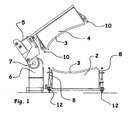
- Fig. 1 is cross-sectional view through a mould assembly for a wind turbine blade during closure of the mould assembly.
- the mould assembly includes a first mould part 2, a second mould part 4 and a hinge mechanism 6, which enables turning of the second mould part 4 in relation to the first mould part 2.
- the blade shell halves 3 are moulded in the two mould parts in a first (not-shown) position of the mould assembly, in which the second mould part 4 is turned 180° in relation to the first mould part 2 such that the openings of both mould parts face upwards.
- the first mould part 2 is provided with a number of protractile guide rods 8 being shown in Fig. 1 in a not yet activated, retracted position.
- the hinge mechanism 6 is here shown as a separate unit attached to the two mould parts 2, 4 and includes not-shown drive means for turning the two mould parts in relation to each other.
- the portion of the hinge mechanism 6 rotating the second mould part 4 is provided with movable elements 5 to enable an accurate positioning of the second mould part 4 above the first mould part 2 and making it possible to compensate for any tolerances when the hinge mechanism is being secured to the mould parts.
- Fig. 2 illustrates the upper mould part 4 in a second partially closed position, in which it is arranged above the first mould part 2 at a distance - typically 300-500 mm therefrom.
- the protractile guide rods 8 are moved upwards towards the bearing means 10 mounted on the upper mould part 4 so as to receive the free ends 9 of the guide rods 8.
- the free ends 9 of the guide rods 8 and the bearing means 10 are conically shaped to guide the ends 9 of the guide rods 8 into reliable engagement with the bearing means 10.
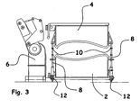
- Fig. 3 illustrates the mould assembly in its second partially closed position, in which the upper mould part 4 has been disengaged from the hinge mechanism 6 and now rests exclusively on the protractile guide rods 8.
- the upper mould part 4 may consequently be guided with an unprecedented high accuracy to a third, not-shown, position, in which the mould parts 2, 4 are made to engage each other along their edges, and in which position the two blade shell halves 3 are glued together.
- the second mould part 4 is lifted again by means of the guide rods 8.
- the portion of the second mould part 4 in the tip of the wind turbine blade may be lifted first to obtain a slip effect.
- the number and position of the guide rods 8 and associated bearing means 10 depend on the mould length, which may be up to 60 metres or even more.
- the drive means 12 of the guide rods 8 may be controlled individually to obtain the desired slip effect.
- Figs. 4-8 illustrate additional advantageous details of the mould assembly according to the invention which are not shown in the preceding figures.
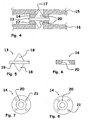
- Fig. 4 is a sectional view through a flange 16 secured to the two longitudinal sides of the first mould part 2 and through a flange 15 secured to the longitudinal sides of the second mould part 4 in the third, closed position of the mould part.
- Apertured members 14, 17 are secured to the flanges 16, 15, said bodies having conical holes 20, which in Fig. 4 each receives a guide pin 13.
- the guide pin 13 includes two conical ends 18 and a shoulder 19. Prior to closure of the mould assembly, one conical tip 18 of the guide pin 13 is inserted into the pilot hole 20 of the apertured member 17.
- Fig. 6 is a cross-sectional view of the apertured member 14, the conical hole 20 being visible.
- Fig. 7 is an end view of the apertured member 14 as seen from the end in which the conical pilot hole 20 has the largest diameter. Pin holes 21 serve to secure the apertured member to the flanges 15, 16.
- Fig. 8 shows an optional embodiment of the apertured member 14, in which the pilot hole 20 is arranged eccentrically.
- This apertured member may be mounted in four different positions, whereby the pilot hole 20 can be adjusted in four different positions to compensate for any tolerances.
- the pin holes 21 may be shaped as oblong or circular segment-shaped holes to increase the fine-adjusting options in relation to the position of the pilot hole 20.
Landscapes
- Engineering & Computer Science (AREA)
- Mechanical Engineering (AREA)
- Chemical & Material Sciences (AREA)
- Composite Materials (AREA)
- Sustainable Development (AREA)
- Combustion & Propulsion (AREA)
- General Engineering & Computer Science (AREA)
- Life Sciences & Earth Sciences (AREA)
- Sustainable Energy (AREA)
- Wind Motors (AREA)
- Moulds For Moulding Plastics Or The Like (AREA)
- Structures Of Non-Positive Displacement Pumps (AREA)
- Moulding By Coating Moulds (AREA)
- Seal Device For Vehicle (AREA)
- Vehicle Interior And Exterior Ornaments, Soundproofing, And Insulation (AREA)
- Cooling, Air Intake And Gas Exhaust, And Fuel Tank Arrangements In Propulsion Units (AREA)
- Perforating, Stamping-Out Or Severing By Means Other Than Cutting (AREA)
- Air-Flow Control Members (AREA)
Applications Claiming Priority (3)
| Application Number | Priority Date | Filing Date | Title |
|---|---|---|---|
| DK200201743 | 2002-11-12 | ||
| DK200201743A DK200201743A (da) | 2002-11-12 | 2002-11-12 | Formindretning med lukkemekanisme |
| PCT/DK2003/000777 WO2004043679A1 (en) | 2002-11-12 | 2003-11-12 | Mould assembly with closure mechanism |
Publications (2)
| Publication Number | Publication Date |
|---|---|
| EP1562733A1 EP1562733A1 (en) | 2005-08-17 |
| EP1562733B1 true EP1562733B1 (en) | 2008-02-20 |
Family
ID=32309263
Family Applications (1)
| Application Number | Title | Priority Date | Filing Date |
|---|---|---|---|
| EP03770926A Expired - Lifetime EP1562733B1 (en) | 2002-11-12 | 2003-11-12 | Mould assembly with closure mechanism |
Country Status (9)
| Country | Link |
|---|---|
| US (1) | US7223091B2 (zh) |
| EP (1) | EP1562733B1 (zh) |
| CN (1) | CN100475500C (zh) |
| AT (1) | ATE386626T1 (zh) |
| AU (1) | AU2003280318A1 (zh) |
| DE (1) | DE60319261T2 (zh) |
| DK (2) | DK200201743A (zh) |
| ES (1) | ES2301843T3 (zh) |
| WO (1) | WO2004043679A1 (zh) |
Cited By (2)
| Publication number | Priority date | Publication date | Assignee | Title |
|---|---|---|---|---|
| EP2380720A1 (en) | 2010-04-22 | 2011-10-26 | Vestas Wind Systems A/S | An improved wind turbine blade manufacturing arrangement |
| WO2012126479A3 (en) * | 2011-03-23 | 2012-12-06 | Vestas Wind Systems A/S | Molding apparatus for making a wind turbine blade and method of making same |
Families Citing this family (48)
| Publication number | Priority date | Publication date | Assignee | Title |
|---|---|---|---|---|
| PT1695813E (pt) * | 2005-02-24 | 2007-07-02 | Vestas Wind Sys As | Método de fabricação de uma pá de turbina eólica, instalação de fabricação de pás de turbina eólica e sua utilização. |
| DK200501539A (da) | 2005-11-08 | 2007-05-09 | Lm Glasfiber As | Formindretning med hængselmekanisme og fremgangsmåde til lukning af en formindretning |
| US20090146433A1 (en) * | 2007-12-07 | 2009-06-11 | General Electric Company | Method and apparatus for fabricating wind turbine components |
| US8012299B2 (en) * | 2008-03-05 | 2011-09-06 | Vestas Wind Systems A/S | Assembly tool and a method of manufacturing a blade |
| BRPI0822519A8 (pt) | 2008-03-13 | 2015-10-13 | Tecsis Tecnologia E Sist Avancados Ltda | Método e dispositivo para manusear pás de aerogeradores |
| GB0805713D0 (en) * | 2008-03-28 | 2008-04-30 | Blade Dynamics Ltd | A wind turbine blade |
| DE102008038620A1 (de) * | 2008-06-27 | 2009-12-31 | Powerblades Gmbh | Verfahren und Fertigungsform zur Fertigung eines Rotorblattes für eine Windenergieanlage |
| ES2377369B1 (es) * | 2008-07-31 | 2013-02-05 | Manuel Torres Martínez | Útil para la fabricación de componentes de aerodinos y aerogeneradores y proceso de fabricación de estos componentes. |
| US8117725B2 (en) * | 2008-10-31 | 2012-02-21 | The Gillette Company | Method of manufacturing a plurality of molded components |
| US8357325B2 (en) * | 2008-12-10 | 2013-01-22 | General Electric Company | Moulds with integrated heating and methods of making the same |
| CN102271885B (zh) * | 2008-12-31 | 2013-11-27 | 泰克西斯先进技术及体系公司 | 具有锁定机构的转子叶片模具组件 |
| EP2230070A1 (en) * | 2009-03-06 | 2010-09-22 | Lm Glasfiber A/S | Method and manufacturing line for manufacturing wind turbine blades |
| EP2226186A1 (en) * | 2009-03-06 | 2010-09-08 | Lm Glasfiber A/S | Method and manufacturing line for manufacturing wind turbine blades |
| CN201357535Y (zh) * | 2009-03-13 | 2009-12-09 | 苏州红枫风电模具有限公司 | 用于大型组合式模具的可调整的对齐装置 |
| CN201357528Y (zh) * | 2009-03-13 | 2009-12-09 | 苏州红枫风电模具有限公司 | 风轮机叶片模具 |
| JP4999116B2 (ja) * | 2009-03-14 | 2012-08-15 | 栗林機工株式会社 | 風力発電翼の反転支持装置 |
| EP2427311A2 (en) * | 2009-05-04 | 2012-03-14 | Mag Ias Llc. | Rapid material placement application for wind turbine blade manufacture |
| ES2365571B1 (es) * | 2009-05-21 | 2012-09-17 | Danobat S.Coop | Sistema para la fabricacion automatica de palas de aerogenerador |
| ES2423186T3 (es) * | 2009-08-20 | 2013-09-18 | Siemens Aktiengesellschaft | Estructura de plástico reforzado con fibra y método para producir la estructura de plástico reforzado con fibra |
| CN201525098U (zh) * | 2009-09-10 | 2010-07-14 | 苏州红枫风电模具有限公司 | 模具翻转系统 |
| EP2305998B1 (en) * | 2009-09-29 | 2016-06-15 | Vestas Wind Systems A/S | Mould for manufacturing of wind turbine blades |
| EP2316629B1 (en) * | 2009-10-27 | 2012-05-23 | Lm Glasfiber A/S | Modular mould system for manufacturing a shell part |
| WO2012010331A1 (en) | 2010-07-21 | 2012-01-26 | Siemens Aktiengesellschaft | Mould assembly and method of closing a mould assembly |
| ES2388865B1 (es) * | 2010-12-23 | 2013-09-06 | Gamesa Innovation & Tech Sl | Molde de conchas partido para palas de aerogenerador, metodo de fabricacion de dicho molde y metodo de fabricacion de pala empleando dicho molde. |
| DK2508321T3 (en) * | 2011-04-04 | 2014-03-10 | Siemens Ag | Mold part, mold unit and method of closing a mold unit |
| ES2613639T3 (es) | 2011-07-28 | 2017-05-25 | Vestas Wind Systems A/S | Instalación de producción que comprende un sistema de transporte para procesar productos alargados, en particular palas de turbina eólica, con conjuntos de molde alargados |
| EP2771160B1 (en) * | 2011-10-27 | 2015-11-25 | Vestas Wind Systems A/S | A production apparatus and a method for manufacturing elongated products such as wind turbine blades |
| WO2013113817A1 (en) * | 2012-02-02 | 2013-08-08 | Lm Wp Patent Holding A/S | A post-moulding station and an associated method of manufacture of a wind turbine blade |
| EP2809499B1 (en) * | 2012-02-02 | 2020-07-22 | LM WP Patent Holding A/S | A system and method for manufacturing a wind turbine blade |
| CN102601893A (zh) * | 2012-02-29 | 2012-07-25 | 哈尔滨工业大学(威海) | 用于加工风力发电机叶片的模具 |
| JP2015531694A (ja) * | 2012-05-30 | 2015-11-05 | ユーウィンエナジー・ゲーエムベーハー | ブレードセクションを組み立てるための装置 |
| CN104918762B (zh) * | 2012-11-20 | 2017-02-15 | 维斯塔斯风力系统有限公司 | 具有避雷保护的风轮机叶片 |
| PL3025836T3 (pl) | 2014-11-27 | 2018-10-31 | Lm Wind Power International Technology Ii Aps | Urządzenie obracające do obracania pierwszej części formy do wytwarzania części łopaty turbiny wiatrowej względem drugiej części formy |
| US10035300B2 (en) * | 2015-06-23 | 2018-07-31 | The Boeing Company | System and method for manufacturing a stiffened composite structure |
| CN105196019A (zh) * | 2015-09-02 | 2015-12-30 | 天津市盛佳怡电子有限公司 | 一种新型的风力发电机叶片翻转圈车 |
| DE102016003326A1 (de) * | 2016-03-21 | 2017-09-21 | Carbon Rotec Gmbh & Co. Kg | Formwerkzeuganordnung |
| DE102016007304A1 (de) * | 2016-06-16 | 2017-12-21 | Senvion Gmbh | Fluchtweg für eine Herstellungsform eines Rotorblattes |
| DE102016008125A1 (de) * | 2016-07-05 | 2018-01-11 | Senvion Gmbh | Herstellungsform eines Rotorblattes |
| US10800071B2 (en) | 2016-09-30 | 2020-10-13 | Gurit Tooling (Taicang) Co., Ltd. | Floor locking device for a wind turbine blade mould |
| EP3535490B1 (en) * | 2016-12-21 | 2022-10-19 | Siemens Gamesa Renewable Energy A/S | Method of applying a protective layer to a wind turbine rotor blade |
| US11572861B2 (en) * | 2017-01-31 | 2023-02-07 | General Electric Company | Method for forming a rotor blade for a wind turbine |
| GB2561851A (en) * | 2017-04-25 | 2018-10-31 | Airbus Operations Ltd | Fibre reinforced composite aerofoil structures |
| EP3596337A1 (en) | 2017-05-09 | 2020-01-22 | Siemens Gamesa Renewable Energy A/S | Lightning protection system for a wind turbine blade |
| WO2019149885A1 (en) | 2018-02-01 | 2019-08-08 | Lm Wind Power International Technology Ii Aps | Connection of mould parts |
| US11135745B2 (en) * | 2018-03-21 | 2021-10-05 | Tpi Composites, Inc. | Mold with thermally conductive flanges |
| ES2949268T3 (es) * | 2019-05-28 | 2023-09-27 | Siemens Gamesa Renewable Energy As | Un molde para fabricar una pala de turbina eólica y un método para fabricar una pala de turbina eólica |
| WO2022170018A1 (en) * | 2021-02-04 | 2022-08-11 | Tpi Composites, Inc. | Modular molding units for fabrication of wind turbine blades |
| EP4186683B1 (en) * | 2021-11-30 | 2024-05-01 | LM Wind Power A/S | System and method for assembling a wind turbine blade shell |
Family Cites Families (15)
| Publication number | Priority date | Publication date | Assignee | Title |
|---|---|---|---|---|
| US3161911A (en) * | 1962-10-02 | 1964-12-22 | Foam Products Corp | Mold for foamed panels and the like |
| DE2146245C3 (de) | 1971-09-16 | 1975-09-04 | Desma-Werke Gmbh, 2807 Uesen | Formwerkzeuge, Insbesondere zum Herstellen von Formungen aus Polyurethan |
| US3981671A (en) * | 1975-09-22 | 1976-09-21 | Cincinnati Milacron, Inc. | Liquid reaction molding press |
| US4080145A (en) | 1976-09-30 | 1978-03-21 | Schloemann-Sieman Aktiengesellschaft | Apparatus for processing foamed plastic |
| DE2810789C3 (de) * | 1978-03-13 | 1981-05-27 | Herbert Kannegiesser Gmbh + Co, 4973 Vlotho | Vorrichtung zur Herstellung von Formkörpern aus schäumbaren Kunststoffen |
| DE2940114C2 (de) * | 1979-10-03 | 1984-03-15 | Krauss-Maffei AG, 8000 München | Vorrichtung zum Formen von Gegenständen |
| DE3014347C2 (de) | 1980-04-15 | 1983-05-26 | Messerschmitt-Bölkow-Blohm GmbH, 8000 München | Verfahren zur Herstellung von schaumkerngestützen, faserverstärkten Kunststoff-Formkörpern wie Flügel, Rotorblätter etc. großer Längen-und Breitenausdehnung |
| GB2119303B (en) | 1982-04-03 | 1985-12-24 | British Aerospace | Mould |
| DE3407765C1 (de) | 1984-03-02 | 1990-01-25 | Deutsche Basaltsteinwolle GmbH, 3406 Bovenden | Verfahren und Vorrichtung zur Herstellung von insbes. schalen- oder rohrartigen Formkoerpern,insbes. Hohlkoerpern |
| US5282732A (en) * | 1992-04-08 | 1994-02-01 | Davidson Textron Inc. | Mold press assembly |
| JP3418207B2 (ja) * | 1992-07-27 | 2003-06-16 | 極東精機株式会社 | 成形用型の開閉装置 |
| DK171948B1 (da) * | 1994-11-04 | 1997-08-25 | Soren Olsen | Fremgangsmaade og form til fremstilling af hule profiler fortrinsvis vindmollevinger i fiberforstaerket matrix saasom glasfiber |
| US6113382A (en) * | 1998-03-16 | 2000-09-05 | Konal Engineering And Equipment Inc. | Press with swingable top press plate |
| CA2237736C (en) | 1998-06-22 | 2004-06-08 | Cole H.C. Beadon | A process for manufacturing fibre reinforced plastic masts, spars or columns |
| DK200001281A (da) | 2000-08-30 | 2002-03-01 | Lm Glasfiber As | Indretning til lukning af form, form omfattende en sådan indretning samt et system omfattende sådanne indretninger. |
-
2002
- 2002-11-12 DK DK200201743A patent/DK200201743A/da not_active Application Discontinuation
-
2003
- 2003-11-12 US US10/535,018 patent/US7223091B2/en not_active Expired - Lifetime
- 2003-11-12 AU AU2003280318A patent/AU2003280318A1/en not_active Abandoned
- 2003-11-12 DE DE60319261T patent/DE60319261T2/de not_active Expired - Lifetime
- 2003-11-12 DK DK03770926T patent/DK1562733T3/da active
- 2003-11-12 ES ES03770926T patent/ES2301843T3/es not_active Expired - Lifetime
- 2003-11-12 AT AT03770926T patent/ATE386626T1/de not_active IP Right Cessation
- 2003-11-12 EP EP03770926A patent/EP1562733B1/en not_active Expired - Lifetime
- 2003-11-12 CN CNB200380103063XA patent/CN100475500C/zh not_active Expired - Lifetime
- 2003-11-12 WO PCT/DK2003/000777 patent/WO2004043679A1/en active IP Right Grant
Cited By (2)
| Publication number | Priority date | Publication date | Assignee | Title |
|---|---|---|---|---|
| EP2380720A1 (en) | 2010-04-22 | 2011-10-26 | Vestas Wind Systems A/S | An improved wind turbine blade manufacturing arrangement |
| WO2012126479A3 (en) * | 2011-03-23 | 2012-12-06 | Vestas Wind Systems A/S | Molding apparatus for making a wind turbine blade and method of making same |
Also Published As
| Publication number | Publication date |
|---|---|
| ES2301843T3 (es) | 2008-07-01 |
| DK1562733T3 (da) | 2008-05-19 |
| US7223091B2 (en) | 2007-05-29 |
| AU2003280318A1 (en) | 2004-06-03 |
| CN1711162A (zh) | 2005-12-21 |
| WO2004043679A1 (en) | 2004-05-27 |
| US20060034971A1 (en) | 2006-02-16 |
| DE60319261T2 (de) | 2009-02-12 |
| CN100475500C (zh) | 2009-04-08 |
| DK200201743A (da) | 2004-05-13 |
| ATE386626T1 (de) | 2008-03-15 |
| DE60319261D1 (de) | 2008-04-03 |
| EP1562733A1 (en) | 2005-08-17 |
Similar Documents
| Publication | Publication Date | Title |
|---|---|---|
| EP1562733B1 (en) | Mould assembly with closure mechanism | |
| CN107000329B (zh) | 使制造风力涡轮机叶片部件的第一模具部件相对于第二模具部件翻转的翻转装置 | |
| US8770966B2 (en) | Mould assembly with hinge mechanism and method for closing a mould assembly | |
| EP2126349B1 (en) | A wind turbine blade and method for assembling a wind turbine blade | |
| EP3475068B1 (en) | Manufacture of a wind turbine blade | |
| US8096778B2 (en) | Structural beam for a wind generator blade production method thereof | |
| US8454791B2 (en) | Method for assembling a rotor blade for a wind turbine | |
| US10632689B2 (en) | Wind turbine blade manufacture | |
| EP2465667B1 (en) | Airfoil manufacturing system | |
| EP2305998A2 (en) | Mould for manufacturing of wind turbine blades | |
| JP2010519120A (ja) | 複合材料から部品、特に飛行機の機体部分を製造する方法および装置 | |
| US9573325B2 (en) | Mould shell section for a mould shell for a wind turbine blade, mould shell and method using the mould shell sections | |
| JP7266613B2 (ja) | 磁気装着フランジ | |
| US10328640B2 (en) | Wind turbine blade manufacturing system and method | |
| EP3723972B1 (en) | A system and method for manufacturing a reinforced wind turbine blade | |
| CN112955310A (zh) | 检测系统、方法及其检测装置 | |
| EP4265906A1 (en) | Support for rotating a composite part and related methods |
Legal Events
| Date | Code | Title | Description |
|---|---|---|---|
| PUAI | Public reference made under article 153(3) epc to a published international application that has entered the european phase |
Free format text: ORIGINAL CODE: 0009012 |
|
| 17P | Request for examination filed |
Effective date: 20050510 |
|
| AK | Designated contracting states |
Kind code of ref document: A1 Designated state(s): AT BE BG CH CY CZ DE DK EE ES FI FR GB GR HU IE IT LI LU MC NL PT RO SE SI SK TR |
|
| AX | Request for extension of the european patent |
Extension state: AL LT LV MK |
|
| DAX | Request for extension of the european patent (deleted) | ||
| GRAP | Despatch of communication of intention to grant a patent |
Free format text: ORIGINAL CODE: EPIDOSNIGR1 |
|
| GRAS | Grant fee paid |
Free format text: ORIGINAL CODE: EPIDOSNIGR3 |
|
| GRAA | (expected) grant |
Free format text: ORIGINAL CODE: 0009210 |
|
| AK | Designated contracting states |
Kind code of ref document: B1 Designated state(s): AT BE BG CH CY CZ DE DK EE ES FI FR GB GR HU IE IT LI LU MC NL PT RO SE SI SK TR |
|
| REG | Reference to a national code |
Ref country code: GB Ref legal event code: FG4D |
|
| REG | Reference to a national code |
Ref country code: CH Ref legal event code: EP |
|
| REG | Reference to a national code |
Ref country code: IE Ref legal event code: FG4D |
|
| REF | Corresponds to: |
Ref document number: 60319261 Country of ref document: DE Date of ref document: 20080403 Kind code of ref document: P |
|
| REG | Reference to a national code |
Ref country code: DK Ref legal event code: T3 |
|
| REG | Reference to a national code |
Ref country code: ES Ref legal event code: FG2A Ref document number: 2301843 Country of ref document: ES Kind code of ref document: T3 |
|
| PG25 | Lapsed in a contracting state [announced via postgrant information from national office to epo] |
Ref country code: FI Free format text: LAPSE BECAUSE OF FAILURE TO SUBMIT A TRANSLATION OF THE DESCRIPTION OR TO PAY THE FEE WITHIN THE PRESCRIBED TIME-LIMIT Effective date: 20080220 |
|
| NLV1 | Nl: lapsed or annulled due to failure to fulfill the requirements of art. 29p and 29m of the patents act | ||
| PG25 | Lapsed in a contracting state [announced via postgrant information from national office to epo] |
Ref country code: AT Free format text: LAPSE BECAUSE OF FAILURE TO SUBMIT A TRANSLATION OF THE DESCRIPTION OR TO PAY THE FEE WITHIN THE PRESCRIBED TIME-LIMIT Effective date: 20080220 |
|
| PG25 | Lapsed in a contracting state [announced via postgrant information from national office to epo] |
Ref country code: BE Free format text: LAPSE BECAUSE OF FAILURE TO SUBMIT A TRANSLATION OF THE DESCRIPTION OR TO PAY THE FEE WITHIN THE PRESCRIBED TIME-LIMIT Effective date: 20080220 Ref country code: SI Free format text: LAPSE BECAUSE OF FAILURE TO SUBMIT A TRANSLATION OF THE DESCRIPTION OR TO PAY THE FEE WITHIN THE PRESCRIBED TIME-LIMIT Effective date: 20080220 |
|
| PG25 | Lapsed in a contracting state [announced via postgrant information from national office to epo] |
Ref country code: PT Free format text: LAPSE BECAUSE OF FAILURE TO SUBMIT A TRANSLATION OF THE DESCRIPTION OR TO PAY THE FEE WITHIN THE PRESCRIBED TIME-LIMIT Effective date: 20080721 Ref country code: SE Free format text: LAPSE BECAUSE OF FAILURE TO SUBMIT A TRANSLATION OF THE DESCRIPTION OR TO PAY THE FEE WITHIN THE PRESCRIBED TIME-LIMIT Effective date: 20080520 Ref country code: NL Free format text: LAPSE BECAUSE OF FAILURE TO SUBMIT A TRANSLATION OF THE DESCRIPTION OR TO PAY THE FEE WITHIN THE PRESCRIBED TIME-LIMIT Effective date: 20080220 Ref country code: SK Free format text: LAPSE BECAUSE OF FAILURE TO SUBMIT A TRANSLATION OF THE DESCRIPTION OR TO PAY THE FEE WITHIN THE PRESCRIBED TIME-LIMIT Effective date: 20080220 Ref country code: CZ Free format text: LAPSE BECAUSE OF FAILURE TO SUBMIT A TRANSLATION OF THE DESCRIPTION OR TO PAY THE FEE WITHIN THE PRESCRIBED TIME-LIMIT Effective date: 20080220 |
|
| PG25 | Lapsed in a contracting state [announced via postgrant information from national office to epo] |
Ref country code: RO Free format text: LAPSE BECAUSE OF FAILURE TO SUBMIT A TRANSLATION OF THE DESCRIPTION OR TO PAY THE FEE WITHIN THE PRESCRIBED TIME-LIMIT Effective date: 20080220 |
|
| EN | Fr: translation not filed | ||
| PLBE | No opposition filed within time limit |
Free format text: ORIGINAL CODE: 0009261 |
|
| STAA | Information on the status of an ep patent application or granted ep patent |
Free format text: STATUS: NO OPPOSITION FILED WITHIN TIME LIMIT |
|
| 26N | No opposition filed |
Effective date: 20081121 |
|
| PG25 | Lapsed in a contracting state [announced via postgrant information from national office to epo] |
Ref country code: EE Free format text: LAPSE BECAUSE OF FAILURE TO SUBMIT A TRANSLATION OF THE DESCRIPTION OR TO PAY THE FEE WITHIN THE PRESCRIBED TIME-LIMIT Effective date: 20080220 Ref country code: BG Free format text: LAPSE BECAUSE OF FAILURE TO SUBMIT A TRANSLATION OF THE DESCRIPTION OR TO PAY THE FEE WITHIN THE PRESCRIBED TIME-LIMIT Effective date: 20080520 Ref country code: FR Free format text: LAPSE BECAUSE OF FAILURE TO SUBMIT A TRANSLATION OF THE DESCRIPTION OR TO PAY THE FEE WITHIN THE PRESCRIBED TIME-LIMIT Effective date: 20081212 |
|
| PG25 | Lapsed in a contracting state [announced via postgrant information from national office to epo] |
Ref country code: MC Free format text: LAPSE BECAUSE OF NON-PAYMENT OF DUE FEES Effective date: 20081130 |
|
| REG | Reference to a national code |
Ref country code: CH Ref legal event code: PL |
|
| PG25 | Lapsed in a contracting state [announced via postgrant information from national office to epo] |
Ref country code: CY Free format text: LAPSE BECAUSE OF FAILURE TO SUBMIT A TRANSLATION OF THE DESCRIPTION OR TO PAY THE FEE WITHIN THE PRESCRIBED TIME-LIMIT Effective date: 20080220 |
|
| PG25 | Lapsed in a contracting state [announced via postgrant information from national office to epo] |
Ref country code: IT Free format text: LAPSE BECAUSE OF FAILURE TO SUBMIT A TRANSLATION OF THE DESCRIPTION OR TO PAY THE FEE WITHIN THE PRESCRIBED TIME-LIMIT Effective date: 20080220 |
|
| PG25 | Lapsed in a contracting state [announced via postgrant information from national office to epo] |
Ref country code: CH Free format text: LAPSE BECAUSE OF NON-PAYMENT OF DUE FEES Effective date: 20081130 Ref country code: LI Free format text: LAPSE BECAUSE OF NON-PAYMENT OF DUE FEES Effective date: 20081130 Ref country code: IE Free format text: LAPSE BECAUSE OF NON-PAYMENT OF DUE FEES Effective date: 20081112 |
|
| PG25 | Lapsed in a contracting state [announced via postgrant information from national office to epo] |
Ref country code: LU Free format text: LAPSE BECAUSE OF NON-PAYMENT OF DUE FEES Effective date: 20081112 Ref country code: HU Free format text: LAPSE BECAUSE OF FAILURE TO SUBMIT A TRANSLATION OF THE DESCRIPTION OR TO PAY THE FEE WITHIN THE PRESCRIBED TIME-LIMIT Effective date: 20080821 |
|
| PG25 | Lapsed in a contracting state [announced via postgrant information from national office to epo] |
Ref country code: TR Free format text: LAPSE BECAUSE OF FAILURE TO SUBMIT A TRANSLATION OF THE DESCRIPTION OR TO PAY THE FEE WITHIN THE PRESCRIBED TIME-LIMIT Effective date: 20080220 |
|
| PG25 | Lapsed in a contracting state [announced via postgrant information from national office to epo] |
Ref country code: GR Free format text: LAPSE BECAUSE OF FAILURE TO SUBMIT A TRANSLATION OF THE DESCRIPTION OR TO PAY THE FEE WITHIN THE PRESCRIBED TIME-LIMIT Effective date: 20080521 |
|
| PGFP | Annual fee paid to national office [announced via postgrant information from national office to epo] |
Ref country code: GB Payment date: 20221021 Year of fee payment: 20 Ref country code: ES Payment date: 20221201 Year of fee payment: 20 Ref country code: DK Payment date: 20221020 Year of fee payment: 20 Ref country code: DE Payment date: 20221020 Year of fee payment: 20 |
|
| P01 | Opt-out of the competence of the unified patent court (upc) registered |
Effective date: 20230522 |
|
| REG | Reference to a national code |
Ref country code: DE Ref legal event code: R071 Ref document number: 60319261 Country of ref document: DE |
|
| REG | Reference to a national code |
Ref country code: DK Ref legal event code: EUP Expiry date: 20231112 |
|
| REG | Reference to a national code |
Ref country code: ES Ref legal event code: FD2A Effective date: 20231124 |
|
| REG | Reference to a national code |
Ref country code: GB Ref legal event code: PE20 Expiry date: 20231111 |
|
| PG25 | Lapsed in a contracting state [announced via postgrant information from national office to epo] |
Ref country code: GB Free format text: LAPSE BECAUSE OF EXPIRATION OF PROTECTION Effective date: 20231111 |
|
| PG25 | Lapsed in a contracting state [announced via postgrant information from national office to epo] |
Ref country code: ES Free format text: LAPSE BECAUSE OF EXPIRATION OF PROTECTION Effective date: 20231113 |
|
| PG25 | Lapsed in a contracting state [announced via postgrant information from national office to epo] |
Ref country code: GB Free format text: LAPSE BECAUSE OF EXPIRATION OF PROTECTION Effective date: 20231111 Ref country code: ES Free format text: LAPSE BECAUSE OF EXPIRATION OF PROTECTION Effective date: 20231113 |