EP1562526B1 - Fussgelenkorthose - Google Patents
Fussgelenkorthose Download PDFInfo
- Publication number
- EP1562526B1 EP1562526B1 EP03783062A EP03783062A EP1562526B1 EP 1562526 B1 EP1562526 B1 EP 1562526B1 EP 03783062 A EP03783062 A EP 03783062A EP 03783062 A EP03783062 A EP 03783062A EP 1562526 B1 EP1562526 B1 EP 1562526B1
- Authority
- EP
- European Patent Office
- Prior art keywords
- ankle
- foot
- medial
- anterior
- orthosis according
- Prior art date
- Legal status (The legal status is an assumption and is not a legal conclusion. Google has not performed a legal analysis and makes no representation as to the accuracy of the status listed.)
- Expired - Lifetime
Links
- 210000002683 foot Anatomy 0.000 claims abstract description 164
- 210000003423 ankle Anatomy 0.000 claims abstract description 56
- 239000011347 resin Substances 0.000 claims abstract description 9
- 229920005989 resin Polymers 0.000 claims abstract description 9
- 239000004744 fabric Substances 0.000 claims abstract description 5
- 239000000835 fiber Substances 0.000 claims description 75
- 210000002414 leg Anatomy 0.000 claims description 43
- 239000000463 material Substances 0.000 claims description 29
- 230000002787 reinforcement Effects 0.000 claims description 14
- 239000003365 glass fiber Substances 0.000 claims description 13
- 229920000049 Carbon (fiber) Polymers 0.000 claims description 12
- 239000004760 aramid Substances 0.000 claims description 12
- 229920006231 aramid fiber Polymers 0.000 claims description 12
- 239000004917 carbon fiber Substances 0.000 claims description 12
- 239000004753 textile Substances 0.000 claims description 10
- 230000007423 decrease Effects 0.000 claims description 8
- 210000002303 tibia Anatomy 0.000 claims description 6
- 239000000088 plastic resin Substances 0.000 claims description 4
- 239000011248 coating agent Substances 0.000 claims description 3
- 238000000576 coating method Methods 0.000 claims description 3
- 239000002131 composite material Substances 0.000 claims description 2
- 230000003014 reinforcing effect Effects 0.000 claims 1
- 210000003371 toe Anatomy 0.000 description 21
- 230000005021 gait Effects 0.000 description 20
- 210000001699 lower leg Anatomy 0.000 description 12
- 244000309466 calf Species 0.000 description 6
- 238000013461 design Methods 0.000 description 6
- 210000003205 muscle Anatomy 0.000 description 6
- 230000032798 delamination Effects 0.000 description 5
- 239000004814 polyurethane Substances 0.000 description 5
- 229920002635 polyurethane Polymers 0.000 description 5
- 230000006735 deficit Effects 0.000 description 4
- 229920001296 polysiloxane Polymers 0.000 description 4
- 208000004067 Flatfoot Diseases 0.000 description 3
- 229920002334 Spandex Polymers 0.000 description 3
- 230000008901 benefit Effects 0.000 description 3
- 230000006835 compression Effects 0.000 description 3
- 238000007906 compression Methods 0.000 description 3
- 210000003127 knee Anatomy 0.000 description 3
- VNWKTOKETHGBQD-UHFFFAOYSA-N methane Chemical compound C VNWKTOKETHGBQD-UHFFFAOYSA-N 0.000 description 3
- 229920003023 plastic Polymers 0.000 description 3
- 239000004033 plastic Substances 0.000 description 3
- -1 polyethylene Polymers 0.000 description 3
- 239000004759 spandex Substances 0.000 description 3
- OKTJSMMVPCPJKN-UHFFFAOYSA-N Carbon Chemical compound [C] OKTJSMMVPCPJKN-UHFFFAOYSA-N 0.000 description 2
- 229920000742 Cotton Polymers 0.000 description 2
- 239000004698 Polyethylene Substances 0.000 description 2
- 241001227561 Valgus Species 0.000 description 2
- 210000001361 achilles tendon Anatomy 0.000 description 2
- 238000005452 bending Methods 0.000 description 2
- 210000000988 bone and bone Anatomy 0.000 description 2
- 229910052799 carbon Inorganic materials 0.000 description 2
- 238000006243 chemical reaction Methods 0.000 description 2
- 230000000295 complement effect Effects 0.000 description 2
- 238000010276 construction Methods 0.000 description 2
- 230000000694 effects Effects 0.000 description 2
- 239000006260 foam Substances 0.000 description 2
- 238000004519 manufacturing process Methods 0.000 description 2
- 210000000113 medial cuneiform Anatomy 0.000 description 2
- 238000000034 method Methods 0.000 description 2
- 230000002232 neuromuscular Effects 0.000 description 2
- 229920001084 poly(chloroprene) Polymers 0.000 description 2
- 229920000573 polyethylene Polymers 0.000 description 2
- 229920000642 polymer Polymers 0.000 description 2
- 230000000087 stabilizing effect Effects 0.000 description 2
- 210000004243 sweat Anatomy 0.000 description 2
- 230000007704 transition Effects 0.000 description 2
- 206010071050 Ankle deformity Diseases 0.000 description 1
- 206010008190 Cerebrovascular accident Diseases 0.000 description 1
- 239000004593 Epoxy Substances 0.000 description 1
- 206010061159 Foot deformity Diseases 0.000 description 1
- 208000008454 Hyperhidrosis Diseases 0.000 description 1
- 239000004677 Nylon Substances 0.000 description 1
- 206010033372 Pain and discomfort Diseases 0.000 description 1
- 206010033799 Paralysis Diseases 0.000 description 1
- 206010034620 Peripheral sensory neuropathy Diseases 0.000 description 1
- 208000006011 Stroke Diseases 0.000 description 1
- 238000010521 absorption reaction Methods 0.000 description 1
- 230000009471 action Effects 0.000 description 1
- 238000013459 approach Methods 0.000 description 1
- 210000000544 articulatio talocruralis Anatomy 0.000 description 1
- 230000015572 biosynthetic process Effects 0.000 description 1
- 230000037396 body weight Effects 0.000 description 1
- 208000026106 cerebrovascular disease Diseases 0.000 description 1
- 230000008859 change Effects 0.000 description 1
- 238000005336 cracking Methods 0.000 description 1
- 125000004122 cyclic group Chemical group 0.000 description 1
- 230000006378 damage Effects 0.000 description 1
- 230000003247 decreasing effect Effects 0.000 description 1
- 230000001934 delay Effects 0.000 description 1
- 229920001971 elastomer Polymers 0.000 description 1
- 239000011152 fibreglass Substances 0.000 description 1
- 210000001906 first metatarsal bone Anatomy 0.000 description 1
- 229920001821 foam rubber Polymers 0.000 description 1
- 210000001503 joint Anatomy 0.000 description 1
- 239000002648 laminated material Substances 0.000 description 1
- 238000003475 lamination Methods 0.000 description 1
- 229920000126 latex Polymers 0.000 description 1
- 239000004816 latex Substances 0.000 description 1
- 210000003141 lower extremity Anatomy 0.000 description 1
- 239000011159 matrix material Substances 0.000 description 1
- 239000002184 metal Substances 0.000 description 1
- 238000012986 modification Methods 0.000 description 1
- 230000004048 modification Effects 0.000 description 1
- 210000000450 navicular bone Anatomy 0.000 description 1
- 210000005036 nerve Anatomy 0.000 description 1
- 208000018360 neuromuscular disease Diseases 0.000 description 1
- 229920001778 nylon Polymers 0.000 description 1
- 229920006264 polyurethane film Polymers 0.000 description 1
- 230000002265 prevention Effects 0.000 description 1
- 239000012783 reinforcing fiber Substances 0.000 description 1
- 201000005572 sensory peripheral neuropathy Diseases 0.000 description 1
- 230000035939 shock Effects 0.000 description 1
- 230000001148 spastic effect Effects 0.000 description 1
- 208000020431 spinal cord injury Diseases 0.000 description 1
- 208000013460 sweaty Diseases 0.000 description 1
- 208000024891 symptom Diseases 0.000 description 1
- 125000000391 vinyl group Chemical group [H]C([*])=C([H])[H] 0.000 description 1
- 229920002554 vinyl polymer Polymers 0.000 description 1
Images


Classifications
-
- A—HUMAN NECESSITIES
- A61—MEDICAL OR VETERINARY SCIENCE; HYGIENE
- A61F—FILTERS IMPLANTABLE INTO BLOOD VESSELS; PROSTHESES; DEVICES PROVIDING PATENCY TO, OR PREVENTING COLLAPSING OF, TUBULAR STRUCTURES OF THE BODY, e.g. STENTS; ORTHOPAEDIC, NURSING OR CONTRACEPTIVE DEVICES; FOMENTATION; TREATMENT OR PROTECTION OF EYES OR EARS; BANDAGES, DRESSINGS OR ABSORBENT PADS; FIRST-AID KITS
- A61F5/00—Orthopaedic methods or devices for non-surgical treatment of bones or joints; Nursing devices; Anti-rape devices
- A61F5/01—Orthopaedic devices, e.g. splints, casts or braces
- A61F5/0102—Orthopaedic devices, e.g. splints, casts or braces specially adapted for correcting deformities of the limbs or for supporting them; Ortheses, e.g. with articulations
- A61F5/0104—Orthopaedic devices, e.g. splints, casts or braces specially adapted for correcting deformities of the limbs or for supporting them; Ortheses, e.g. with articulations without articulation
- A61F5/0111—Orthopaedic devices, e.g. splints, casts or braces specially adapted for correcting deformities of the limbs or for supporting them; Ortheses, e.g. with articulations without articulation for the feet or ankles
- A61F5/0113—Drop-foot appliances
Definitions
- the present invention relates to orthotic devices utilized to limit the movement of a lower limb. More particularly, the present invention relates to an ankle-foot orthosis for stabilizing and controlling motion of the ankle and foot.
- An ankle-foot orthosis is a medical device used to support and align the ankle and foot by suppressing spastic and overpowering ankle and foot muscles, assisting weak and paralyzed muscles of the ankle and foot, and preventing or correcting ankle and foot deformities.
- An ankle-foot orthosis is particularly useful in assisting the functions of the ankle and foot when a person has a gait condition commonly known as "drop foot.”
- Drop foot is a neuro-muscular condition resulting in the inability of a person to sufficiently lift one of their feet during a walking stride. Drop foot may result from a cerebrovascular accident, spinal cord injury, hereditary and sensory neuropathies, neuromuscular disease or any damage to the muscle and nerves required to activate the muscle of the neuromuscular system related to the foot.
- slap foot There are two common complications from drop foot. First, the individual cannot control the falling of their foot after striking their heel. Consequently, the foot will slap the ground on every step, which is commonly referred to as slap foot. This is typically due to the impairment of a patient's dorsiflexor muscles which are located below the knee on the front of the leg and used to lift the foot from a position substantially aligned with the lower leg to a position substantially perpendicular to the lower leg known as dorsiflexion. Impairment of the dorsiflexor muscles thus results in excessive plantar flexion which is the action of extending the foot from a position substantially perpendicular to the lower leg to a position substantially parallel to the lower leg.
- the second complication is the inability to clear the toe during the swing phase of a gait cycle. This causes the person to drag their toe on the ground throughout the swing phase.
- an ankle-foot orthosis can be prescribed to compensate for the weakness of the dorsiflexors by resisting plantar flexion at the heel strike and swing phase during a gait cycle.
- an individual with drop foot may have little or no function in their anterior tibialis.
- the anterior tibialis originates at the lateral condyle of the tibia and extends along the lateral side of the tibia to cross the tibia near a distal portion thereof over to the medial side of the ankle to connect with the first metatarsal bone and medial cuneiform bone.
- Proper function of the anterior tibialis permits dorsiflexion and inverts the foot at the ankle in a supinated position.
- the anterior tibialis also supports the medial arch of the foot due to its connection to the medial cuneiform bone.
- anterior tibialis tend to pronate during a stance phase of a gait cycle, and supinate the foot during a swing phase of a gait cycle. Furthermore, due to impairment of the anterior tibialis, in particular at the medial arch of the foot, the ankle is typically everted and pronated.
- ankle-foot orthotic devices Over the years, efforts have been made to provide ankle-foot orthotic devices to correct drop foot and enable a patient to walk and function in a relatively normal manner.
- One type of prior art ankle-foot orthosis comprises a dorsal splint of metal or plastic that extends behind the Achilles tendon and merges with a foot plate spanning the sole of the foot.
- This ankle-foot orthosis has at least one strap which extends around the lower leg at a location below the knee.
- This ankle-foot orthosis is disadvantageous in that the orthosis extends along the dorsal portion of the leg and affects the joints unfavorably to produce a very stiff gait.
- This orthosis Another disadvantage to this orthosis is that the calf and Achilles tendon are subjected to heavy stresses which may cause pain and discomfort to the patient wearing the orthosis. Yet further, this orthosis has an undesirable effect on a patient's leg during a gait cycle since the orthosis is solely positioned on the back of the heel and therefore does not provide a smooth heel strike.
- This ankle-foot orthosis is fabricated from carbon fiber reinforced material to provide moderate resistance to plantarflexion and dorsiflexion as well as some coronal plane control.
- the construction of this orthosis includes a footplate connecting to a calf band via a small carbon fiber spring that extends around the medial malleolus and extends up the posterior calf region, and further includes a strap that secures the orthosis to the lower leg.
- the foot plate provides compression at heel strike, energy return from a mid-stance to toe off, easy toe rollover by including increased stiffness from heel strike to midstance and decreased stiffness from midstance.
- This design is less conspicuous when worn, since it extends around the medial malleoulus and the carbon fiber reinforced material is wear resistant. Furthermore, this design has the advantage over conventional plastic posterior designs in that it extends over the medial side of the foot, and therefore provides the orthosis with a heel part and a toe part that contribute to a smoother heelstrike. Contrariwise, a disadvantage to this orthosis is that it permits a significant degree of plantar flexion since it lacks proper anterior support and only reinforces the posterior of the ankle and foot. Moreover, this design does not provide any lateral support, and therefore, unless people wear high and strong shoes, inversion of the foot is not prevented.
- U.S. Patent 5,897,515 discloses an ankle-foot orthosis that includes a frame of flexible material that extends over the anterior portion of the lower leg and the lateral ankle, and further extends beneath a portion of the sole of the foot to connect to a foot plate.
- This orthosis requires at least one substantially inflexible reinforcement element extending over a narrow part of the anterior portion of the frame.
- the anterior shell covering the lower leg can cause a patient discomfort due to the amount of area covered along the anterior portion of the leg, thereby resulting in an excessively sweaty area and an undesirable amount of pressure exerted on the tibia region when walking.
- this orthosis has been found to suffer from breakage problems particularly in a region where the orthosis extends over the lateral ankle and connects to the foot plate.
- a patient may have adequate support during the swing phase of their gait, but will not have sufficient support to prevent eversion of the foot during the stance phase of their gait.
- the lack of support during the stance phase is due in part to the lack of support to the medial arch of the foot and the overall failure of the lateral strut to support the length of the anterior tibialis.
- WO 02/083040 discloses an orthosis that is quite similar to that of US 5 897 515 .
- the former comprises a bifurcated upper leg engaging portion.
- US patent 3 504 668 relates to an orthotic device having a medial arch portion that extends from an ankle portion.
- the medial arch portion connects to a foot portion that only corresponds to an arch of the intended wearer of the device.
- the orthotic device does not include upper leg engaging portions since the upper most portion of the device extends only to the ankle of the wearer of the device.
- the device does not include any section that extends from the ankle portion as to extend over the lateral side of the ankle.of the wearer.
- an ankle-foot orthosis that provides support for both the medial and lateral ankle portions of a patient, dynamic dorsiflexion and plantar flexion support, a foot plate permitting easy toe rollover, and a dynamic design which is more durable and less prone to material failure through normal use.
- Another object of the present invention is to provide an ankle-foot orthosis that provides dynamic plantar flexion support to provide a more natural and dynamic gait while maintaining the foot in a functional position.
- Yet another object of the present invention is to provide an ankle-foot orthosis having a monolithic frame for supporting the anterior portion of the lower leg which does not cover the entire anterior portion of the lower leg while maintaining a light, strong and durable orthosis.
- a further object of the present invention is to provide an ankle-foot orthosis that provides a smooth toe rollover or transition of compressive forces from a heel-strike position to a toe-off position so as to provide a natural feeling when walking while wearing the orthosis.
- the foot plate may have a curvilinear shape and variable stiffness properties between the heel and toe ends.
- the design of the foot plate in the present invention provides a smooth toe rollover or transition of compressive forces from a heel-strike position to a toe-off position thereby providing a natural feeling during a walking stride while a patient wears the orthosis. In areas of the orthosis that are subject to higher degrees of stress relative to other areas, such areas are reinforced with additional reinforcing fibers.
- the orthosis of the present invention includes a medial strut or portion arranged to extend generally along the tibialis anterior and over the medial ankle.
- the orthosis provides a three-point pressure system wherein two pressure points are located on the lateral side of the shoe and the lateral side of an upper calf of the patient.
- the third pressure point extends along the medial strut and prevents the foot from pronating and the ankle from assuming a fixed structural position in which the foot or part of the foot appears everted or in the valgus position.
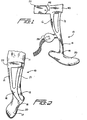
- the ankte-foot orthosis generally comprises a monolithic frame 10 including at least one layer of fabric impregnated with a hardened structural resin.
- the orthosis includes lateral and medial anterior support members 12, 14, respectively, configured and dimensioned to extend downwardly from below a knee of a patient's leg 11 along the anterior of the leg 11 thereby defining a clearance therebetween along a portion of the length of the leg 11.
- the lateral and medial anterior support members 12, 14 join in advance of a patient's ankle joint 13 to define an anterior ankle portion 16.
- the ankle portion 16 preferably extends to a medial connection 18 extending around the medial side of a patient's ankle 13 and connecting to a foot plate 20 located beneath the sole of a patient's foot 17.
- the configuration of the two anterior support members 12, 14 permits easy adjustment around the leg and a preferred fit is achieved by adjusting the two anterior support members 12, 14 relative to one another according to the preference of the patient.
- the configuration of the frame 10 may also permit some forward bend of the leg 11 which provides spring to the region of the frame 10 at an upper portion of the lower leg 11 and relieves some pressure of the orthosis on the leg 11 and ankle 13 near the footplate 20.
- the configuration of the frame 10 enables ample air circulation around the face of the lower leg.
- the two anterior support members 12, 14 preferably remain bifurcated generally two-thirds the distance from their proximal end to the foot plate 20. It has been found that there is an increase in rigidity and decrease in flexibility of the frame if the anterior support members are lengthened resulting in a shortened ankle portion, and conversely, a decrease in rigidity and increase in flexibility if the anterior support members are shortened resulting in an elongated ankle portion. It will be understood that it is within the scope of the present invention to lengthen or shorten the anterior support members from the preferred two-thirds distance length in order to gain greater rigidity or flexibility.
- the anterior support members 12, 14 may have the same rigidity
- the anterior support members may be constructed so that each member has a different stiffness.
- the lateral anterior member may be more rigid than the medial anterior member, or vice versa.
- one of the anterior support members may be longer than the other anterior support member, or similarly, one of the anterior support members may have a greater width or thickness than the other anterior support member. The length, width or thickness of the anterior support members may be optimized to accommodate particular needs of a patient.
- the ankle-foot orthosis may be arranged in at least several different configurations to connect the frame to the leg of a patient.
- the lateral and medial anterior support members 12, 14 are connected by a lateral frame element 40 extending laterally across the leg 11.
- a fastening device 22 configured to wrap around the leg 11 to secure the frame 10 thereon.
- the lateral frame element 40 includes fastener elements 42 arranged to permit the fastening device 22 to be releasably secured therewith.
- buttons and button holes, snap fasteners, or other similar fasteners commonly used may be employed, much preferred are complementary sections of hook-and-loop fastener fabric mounted on opposite overlapping sides of the lateral frame element 40 and the fastening device 22.
- the lateral frame element may be integrated with the frame when the frame is formed, or may alternatively be permanently or releasably secured to the frame after the frame has been formed.
- the lateral frame element may be constructed from structural materials such as resin impregnated glass, carbon or aramid fibers, a polymer such as polyethylene or polyurethane, or any other material suitable for an ankle-foot orthosis known to one skilled in the art. Additionally, the lateral frame element may comprise a textile and padding combination, whether combined with a structural material or taken alone, that is sufficiently rigid to provide support to the patient.
- the fastening device 22 connects to the lateral and medial anterior support members 12, 14 and wraps around the leg 11 to secure the frame therewith.
- the frame 10 of this embodiment which is an embodiment of the present invention, includes upper leg engaging portions 55, 57 that extend from and generally are oriented perpendicularly relative to the anterior support members 12, 14.
- Such upper leg engaging portions 55, 57 are configured to extend around at least a portion of the periphery of the patent's leg 11, thereby providing lateral support to the leg and sufficient surface area to secure the frame 10 to such leg 11.
- the fastener device may be constructed from a textile, elastic band or any other material that may be apparent to one skilled in the art for wrapping around the leg and securing the lateral and medial anterior support members thereon. Moreover, the fastener device may be formed from at least one material having breathable properties which may reduce a build-up of localized areas of sweat on the leg or a material that can store and release energy to withhold desirable temperature to thereby reduce localized regions of sweat.
- hook-and-loop segments 53 of a hook-and-loop material are preferably secured to the anterior support members 12, 14 on the upper engaging portions 55, 57 thereof.
- the fastening device 22 is preferably secured at a fixed end 59 to one of the upper engaging portions 55 and includes a portion of hook-and-loop material complementary to the hook-and-loop segments 53.
- a free end 61 of the fastening device 22 is configured and dimensioned to extend around a patient's leg to couple with the hook-and-loop segments 53.
- the hook-and-loop segments 53 are adhered to the anterior support members as the frame 10 is formed.
- a polymeric coated textile may be pulled over fiber laminates used to form the frame and cured with the fiber laminates in an autoclave. A small incision is made on the textile at a region of the upper engaging portions of the anterior support members where the fastening device will be attached.
- the hook-and-loop segments are glued over the incisions on the textile so that during curing of the resin of the laminate, the resin will leak through the cuts and into the hook-and-loop segment, thereby forming a bond with the hook-and-loop segments.
- the frame 10 includes a fastener strap 44 configured and dimensioned to wrap around an upper calf region of a patient and extend through at least one loop 52 connected to either one or both of the lateral and medial anterior support members 12, 14. Both ends of the fastener strap 44 may include fastener elements 42, such as those mentioned above, which are configured to couple with a corresponding one on an opposite strap end of the fastener strap 44.
- the fastener strap 44 may be fixed onto at least one of the anterior support members 12, 14, or may be an unattached, loose strap that is insertable through the at least one loop 52.
- the orthosis of the present invention may include support members that are used to reinforce the frame.
- Such additional reinforcement members may be releasably secured to the frame or integrated therewith to selectively provide additional support to regions of the leg.
- the frame 10 may be provided with a lateral leg support 26 that extends generally from a location near a proximal portion of the ankle portion 16 and wraps around the calf region of a patient.
- the lateral leg support 26 may be releasably connected to the frame 10 or integrated therewith and include additional layers of preimpregnated fabric, bendable layers of molded glass fibers or reformable prepeg material attached to either interior or exterior portions of the frame 10.
- the lateral leg support may be removed from frame in a manner known to one skilled in the art of orthotics.
- the invention includes a lateral ankle support 24 that is located near a distal portion of the ankle portion 16 and extends laterally thereon.
- the lateral ankle support 24 may be integrated with the frame or may be releasably secured to the frame with fastener elements 42, such as those mentioned above.
- the lateral ankle support can be employed to extend over the patient's foot 17 to provide additional support to prevent supination during the swing phase of a gait cycle, a condition of which is common with drop foot patients.
- the ankle-foot orthosis of the present invention may be configured in a variety of embodiments that are aimed to provide comfort to the patient wearing such an orthosis.
- At least one of the anterior support members may include a padding feature disposed on the surface which faces the patient's leg.
- This padding feature may be coated onto localized surfaces of the frame, integrated within the frame at predetermined areas, or may extend in a continuous web between the anterior support members to span the clearance therebetween.
- Such padding feature is preferably soft and lightweight, provides excellent shock absorption and prevents blistering of the skin.
- Preferred materials used in the padding feature include a flexible foam made from cross-linked, closed cell foam, or silicone layer made from incompressible silicone.
- the padding feature include a textile cover disposed over the aforementioned materials.
- the interior of the anterior support members may include a portion of hook-and-loop material adhered to the surface thereof. Padding material having a corresponding portion of hook-and-loop material may be provided so that a patient can selectively remove or install the padding material to the anterior support members.
- the padding material may be prefabricated to provide an exact fit to the orthosis, generally having the same profile as the portions of the frame. The configuration of the padding material is not limited to being disposed only along the interior surface of the anterior support members, but may also extend over the exterior surface of the anterior support members or around the entire periphery of the orthosis to thereby form a sleeve-like structure.
- a web may be provided to span the clearance between the anterior support members to effectively create a shell over the anterior portion of the leg.
- This web is preferably flexible so as not to impede the function of the anterior support members but sufficiently rigid to provide additional support to the leg.
- the flexible web may be a laminate material, woven glass fibers, neoprene, elastic cotton, rubber, foam rubber, latex, silicone, any other suitable flexible material known to one skilled in the art and any combination thereof.
- the web may not be flexible and may be selected from the group consisting of cotton, canvas, vinyl, nylon, any other suitable flexible material known to one skilled in the art and any combination thereof.
- the web may be sewn, woven, fastened, glued or secured to the frame in any other fashion known to one skilled in the art.
- the frame is preferably constructed of a plurality of layers of woven glass fibers reinforced with a plastic resin.
- the woven glass fibers may be reinforced with resin impregnated carbon or aramid fibers in a plastic resin at specific locations of the frame, thereby providing additional structural strength and varying degrees of flexibility.
- the frame is reinforced with unidirectional carbon fibers along the anterior support members the anterior ankle portion, the medial connection and the foot plate.
- the unidirectional carbon fibers are generally oriented along the longitudinal length of the frame.
- the woven glass fibers are generally oriented at 45 degrees relative to the unidirectional carbon fibers so as to provide optimal strength and flexibility.
- the medial connection and the foot plate be reinforced with a plurality of aramid fibers preimpregnated with an epoxy matrix to provide additional toughness and flexibility required for durability.
- Portions of the frame may exclusively be constructed from woven glass fibers and the orientation of such fibers may be provided in a predetermined manner.
- the upper engaging portions 55, 57 in FIG. 5 extending from the anterior support members be solely constructed from woven glass fibers wherein the glass fibers are preferably oriented at 45 degrees and multiples thereof relative to the width thereof extending around a patient's leg 17.
- the same orientation of glass fibers used in the upper engaging portions may be provided for the lateral leg support 26 in FIG. 1.
- regions of the frame may include additional layers of fibers reinforced with a plastic resin to provide greater structural strength at such regions.
- the medial portion of the frame may have a greater thickness than the anterior support members so as to provide a more rigid connection between the foot plate and the ankle portion and to withstand the forces subjected thereto when a patient walks.
- the frame and the foot plate may include other materials, such as fiber glass, silicone, polyurethane coated lycra, polyurethane film, Alkantara and plastic covered textile as will be apparent to one skilled in the art. Desirable material properties of the frame and the foot plate should possess sufficient resiliency to resist cracking upon application of repeated bending stresses, and ample flexibility to enhance performance characteristics felt by a patient to provide a more natural and dynamic gait while a patient's foot is in a functional position.
- the present invention is not limited to the aforementioned types, location and orientation of fibers, and may be tailored to include or omit certain fibers construction at various locations according to a desired flexibility and strength.
- the frame and foot plate of the present invention may be constructed from a polymer, such as polyethylene or polyurethane, and may selectively be reinforced with at least one structural material or composite.
- Selected regions of the orthosis of the present invention may be coated with a polymeric coated textile, such as a polyurethane coated lycra or neoprene, to provide a smooth surface finish and prevent localized areas of delamination of the fibers.
- a polymeric coated textile such as a polyurethane coated lycra or neoprene
- the selected regions include the surfaces of the anterior support members, ankle anterior portion, the medial portion not in contact with the patient's leg and all of the external surfaces of the foot plate. It will be understood, however, that the coating is not limited to being disposed on the described selected regions and may be provided on any of the surfaces of the frame.
- the coating of the orthosis is performed by stretching a polymeric coated textile over the frame after a laminate fiber lay-up and before the frame is placed in an autoclave.
- the fibers cure with the polyurethane coated lycra as well. This provides the orthosis with a visually appealing surface and prevents splinters from the fibers in the event the orthosis delaminates.
- FIGS. 7A and 7B show the foot plate 20 preferably having a length from toe to heel roughly equal to the sole of the foot 17.
- the foot plate 20 includes a toe end 28, a heel end 32 and an intermediate region 30 therebetween.
- the foot plate 20 substantially conforms to the foot 17 and defines a curvilinear shape having a tapered thickness that generally decreases from the intermediate region 30 to the heel end 32 and toe ends 28.
- the performance of the foot plate 20 is concerned with four positions of the foot 17 during a walking stride.
- the first position of a walking stride entails a heel strike, wherein the patient transfers weight to the heel of the leading foot.
- the flexible nature of the foot plate 20 allows the heel end 32 to bend slightly in the rear portion thereof although most compressive stresses from the weight of the patient are absorbed by the ankle which is reinforced by the medial connection 18. As shown in FIG. 7A, the relative thickness of the heel end 32, as evidenced by the numerals, is greater at regions approaching the intermediate portion 30.
- the second position occurs during midstance or when the patient reaches a generally flat foot-footed position when the foot plate 20 contacts the ground substantially along its entire length.
- the compression weight of the patient in this position is continually shifting from the heel end to the toe end in a movement which is called "rollover.”
- the intermediate region 30 maintains a constant thickness along the length thereof to provide a uniform rollover effect.
- FIG. 7B shows an alternative embodiment of the invention wherein the heel end 32 of the foot plate 20 bends downward 33 relative to the intermediate region 30.
- the downward bend 33 provides additional spring and dampening to the heel end 32 during the rollover and heel-off positions.
- the downward bend 33 delays emergence of the foot condition "flat foot," a condition which occurs when a patient cannot achieve the rigidity of a normal foot and a common early symptom of drop foot.
- the foot plate 20 may alternatively be provided with a variable stiffness as opposed to providing a bend in foot plate 20.
- the third position occurs when the patient pushes off the ball and toe regions of the foot at a terminal stance at the "heel-off" position.
- the toe end 28 is subject to large compressive forces and may bend substantially with the foot of the patient to absorb some of the compressive stresses.
- the relative thickness decreases from the intermediate region 30 to the toe end 28.
- the ankle portion absorbs a majority of the compression generated by the patient, and the foot plate 20 and the ankle portion 16 work to provide dynamic performance.
- the desirable thicknesses of the aforementioned regions of the foot plate 20 may be tailored according to a patient's condition as may be apparent to one skilled in the art. Therefore, the foot plate 20 of the present invention as shown in FIGS. 7A and 7B is not limited to the relative different thicknesses shown therein.
- the foot plate should cover substantially the length of the foot to provide sufficient control to a patient's gait while distributing pressure from the foot
- the foot plate may be positioned offset from a medial side of the foot so as to generally cover a central portion of the sole of the foot. By offsetting the foot plate, pressure can be relieved from an anterior portion of the leg and the ankle. Furthermore, medial portions of the foot plate may be removed to achieve the offset position thereof relative to a medial side of the foot.
- the foot plate of the invention may have a widened lateral portion relative to a medial portion thereof so that the lateral portion of the foot plate presses more against a patient's shoe on the lateral side than on the medial side.
- the widened lateral portion of foot plate is provided so that the medial portion of the orthosis does not aggravate the navicular bone of a patient's foot.
- the foot plate 20 includes unidirectional fiber plies that are layered in combination with woven fiber plies along the length thereof.
- the amount of unidirectional fiber plies and the woven fiber plies provided along different areas 28, 30 and 32 vary in accordance with the different thickness discussed in relation to FIGS. 7A and 7B.
- FIG. 8 shows a force analysis of a healthy person walking to demonstrate how stiffness of a right-footed foot plate of the present invention varies during a right heel strike (RHS), left heel strike (LHS) and right toe off (RTO).
- the solid line 56 represents forces that a person having a normal gait applies to a floor when walking.
- the dashed line 54 represents the stiffness of the foot plate from the heel 32 to the toe 28 ends.
- RHS represents a point taken 1.5 inches from the heel end 32
- LHS represents a point taken 7.5 inches from the heel end 32. It follows that RTO represents a point taken 10 inches from the heel end 32.
- FIG. 9 shows a schematic view illustrating the number of unidirectional fiber plies relative to the woven fiber plies of the foot plate 20.
- FIG. 9 shows a predetermined number of unidirectional plies of fibers positioned along the regions 28, 30 and 32.
- FIG. 9 shows the combined total of unidirectional fiber plies and woven plies of fibers positioned along regions 28, 30 and 32 of the foot plate 20.
- FIG. 10 schematically shows the direction 52 of the unidirectional fibers along the length of the foot plate 20 in relation to the imprint 60 of a patient's foot.
- the fibers are positioned generally in direction 52 which is in the direction of the reaction force movement between the ground and the foot, and tension that builds in the foot plate 20 when a patient is walking.
- the unidirectional fibers 46 of the foot plate 20 are arranged unidirectionally along the length of the foot plate 20 such that layers of fibers 44 extending from the medial connection 18 interleave with the fibers 46 of the foot plate 20.
- the unidirectional fibers 44 change direction when they reach the foot plate 20 and extend in direction 52.
- the interface between the medial connection fibers 44 and the unidirectional fibers 46 is provided to strengthen the orthosis between the medial connection 18 and the foot plate 20 and to reduce the risk of material failure of the orthosis 20 at point 48 between the medial connection 18 and the foot plate 20 which is a prevalent area of orthosis fracture.
- the fibers 44 extending from the medial portion 18 are laid along the foot plate 20 in separate layers to prevent voids in the foot plate 20 and to decrease stresses on the foot plate 20 during a walking stride. It should be noted that by placing all the layers from the medial portion in between the same two layers of the footplate, very high stresses on just one area in the footplate may result. Consequently, there may be a greater number of voids since all the layers extending from the medial portion are bulky, and it follows that it would be difficult to remove the voids between layers.
- a vacuum is applied to the connection between the foot plate 20 and the medial portion 18 in at least one stage in order to reduce air in the lamination of the fiber layers 44, 46. It is important to the present invention that the voids are removed or kept at a minimum since it has been found that durability of the orthosis markedly decreases with a rise in voids between the layers of fibers.
- Aramid fibers may be integrated with the fiber layers 46 of the foot plate 20 to increase the flexibility and toughness thereof, and to reduce the risk of material failure. Aramid fibers are also useful in assisting the prevention of delamination of the fiber layers 44 in the event that the foot plate 20 would shatter. While it is envisioned that aramid fibers may be used in a lower portion of the medial connection 18 connecting to the foot plate 20, aramid fibers may be integrated throughout the orthosis wherever one skilled in the art may deem necessary to increase flexibility and toughness thereof.
- aramid fibers may be integrated in the connection between the medial portion 18 and the footplate 20 where unidirectional aramid fibers turn from the medial portion 18 to the footplate 20.
- unidirectional aramid fibers turn from the medial portion 18 to the footplate 20.
- the fibers may be positioned in a three-dimensional fiber lay-up configuration at preselected portions of the frame.
- a plurality of fibers may be provided and positioned in a different orientation than the unidirectional fibers to create a three-dimensional configuration. It has been found that through cyclic loading, microcracks in the resin of the unidirectional fibers are produced which propagate over time to cause delamination of the layers of unidirectional fibers. By using the three-dimensional approach to laying-up the fibers, delamination of the layers of unidirectional fibers is mitigated since the plurality of fibers oriented in a different direction than the unidirectional fibers bind the unidirectional fibers together.
- the three-dimensional fiber lay-up configuration includes interposing the unidirectional fiber layers with fibers extending at an angle non-parallel to the direction of the unidirectional fibers.
- the unidirectional fiber layers may generally extend along a first plane
- a plurality of fibers generally extending along a second plane may be interposed with the unidirectional fibers extending along the first plane.
- the layers of fibers extending from the medial connection to the foot plate may be considered to extend in directions along the first plane in orientations non-parallel to the unidirectional fibers of the foot plate.
- a plurality of fibers extending in the second plane may be interposed through both the layers of the fibers extending from the medial connection and the foot plate. While the interposed fibers can extend at any angle non-parallel with the unidirectional fibers, it is preferred that the fibers extend perpendicularly to the unidirectional fibers for optimal strength of the configuration.
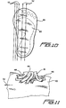
- reinforcement member 62 including at least one layer of a plurality of fibers may be provided to reinforce areas of the medial portion 18 and foot plate 20 susceptible to failure.
- the reinforcement members 62 may be positioned to extend around and over portions of the foot plate 20 at angles non-parallel to the unidirectional fibers of the foot plate and the medial connection. After the initial lay-up of the laminated layers is complete, reinforcement members 62 are wrapped or positioned around the orthosis at areas where delamination may occur.
- the reinforcement members 62 will include fibers that extend generally along a plane perpendicular to the plane of the unidirectional fibers of the foot plate 20. This will occur at least along areas whereat the reinforcement members wrap around the periphery of the medial connection 18 and foot plate 20. Additionally, in areas where portions of the reinforcement members 62 extend generally along the plane of the unidirectional fibers of the foot plate 20 and medial portion 18, such portions of the reinforcement members 62 provide additional reinforcement to the laminated layers of such foot plate 20 and medial portion 18. It will be understood that the invention is not limited to the medial portion and the foot plate having reinforced areas with the three-dimensional fiber configuration, and one skilled in the art may provide the orthosis with reinforced regions having the aforesaid three-dimensional fiber connection where deemed necessary.
- the orthosis of the present invention can be arranged to be directly casted onto a leg and foot of a patient to form a custom fitted orthosis.
- the orthosis of the present invention permits custom fitting and adjusting over a wide range of dimensional variables, it is preferred to provide the present invention in a range of sizes to permit an orthotist to tailor individualized fitting of the devices to a wide range of individuals within different size and profile ranges.
- the orthosis of the present invention can be assembled among a variety of different foot plates, anterior support member, medial portion and ankle portion having various configurations, stiffnesses and sizes.
- the foot plate and medial portion can be custom shaped to a patient's leg and foot, and the remaining components can be preformed and connected to the custom shaped foot plate and medial portion to form the orthosis of the present invention.
Landscapes
- Health & Medical Sciences (AREA)
- Nursing (AREA)
- Orthopedic Medicine & Surgery (AREA)
- Engineering & Computer Science (AREA)
- Biomedical Technology (AREA)
- Heart & Thoracic Surgery (AREA)
- Vascular Medicine (AREA)
- Life Sciences & Earth Sciences (AREA)
- Animal Behavior & Ethology (AREA)
- General Health & Medical Sciences (AREA)
- Public Health (AREA)
- Veterinary Medicine (AREA)
- Orthopedics, Nursing, And Contraception (AREA)
- Prostheses (AREA)
- Saccharide Compounds (AREA)
- Curing Cements, Concrete, And Artificial Stone (AREA)
Claims (20)
- Fußgelenk-Fuß-Orthese mit Außen- und Innenseite, umfassend:einen strukturellen Rahmen (10), der aus zumindest einer Lage mit gehärtetem strukturellem Kunstharz imprägniertem Gewebe gebildet ist und sich von einem oberen, mit dem Bein zusammenwirkenden Anteil abwärts zu einem frontalen Fußgelenksanteil (16) erstreckt, wobei sich der frontale Fußgelenksanteil (16) zu einem inneren Anteil (18) erstreckt, der sich lediglich auf der Innenseite der Orthese befindet und mit einer Fußplatte (20) verbindet, welche sich im etwa entlang der Länge des Fußes des beabsichtigten Trägers der Orthese erstreckt, und eine äußere Fußgelenksstütze (24), dadurch gekennzeichnet, dass der strukturelle Rahmen zwei frontale Stützelemente (12, 14) umfasst, die sich von dem oberen, mit dem Bein zusammenwirkenden Anteil entlang einer Au-ßen- und einer Innenseite des Schienbeins des beabsichtigten Trägers der Orthese erstrecken und an dem frontalen Fußgelenksanteil (16) verbinden; wobei sich die äußere Fußgelenksstütze (24) von dem frontalen Fußgelenksanteil (16) erstreckt und sich auf der Außenseite der Orthese nahe und oberhalb des Fußgelenks eines beabsichtigten Trägers der Orthese befindet; und dadurch, dass das frontale, äußere Stützelement (12), der frontale Fußgelenksanteil (16) und der innere Anteil (18) sich in etwa entlang des vorderen Schienbeinmuskels und des inneren Fußgelenkabschnitts des beabsichtigten Trägers der Orthese erstrecken.
- Fußgelenk-Fuß-Orthese gemäß Anspruch 1, weiterhin umfassend eine Befestigungsvorrichtung (22), die mit den beiden frontalen Stützelementen (12, 14) an dem oberen, mit dem Bein zusammenwirkenden Anteil (55, 57) verbunden ist.
- Fußgelenk-Fuß-Orthese gemäß Anspruch 1 oder 2, wobei die Fußplatte (20) eine gekrümmte Form und eine abnehmende Dicke besitzt, die im Allgemeinen von dem Zwischenbereich (30) zu dem Fersenende (32) und dem Zehenende (28) hin abnimmt.
- Fußgelenk-Fuß-Orthese gemäß Anspruch 3, wobei das Fersenende (32) eine Abwärtsneigung bezogen auf den Zwischenbereich (30) aufweist.
- Fußgelenk-Fuß-Orthese gemäß einem der vorhergehenden Ansprüche, weiterhin umfassend eine äußere Beinstütze (26), die mit dem Rahmen (10) verbunden ist.
- Fußgelenk-Fuß-Orthese gemäß Anspruch 5, wobei die äußere Beinstütze (26) ein Band umfasst, das angeordnet ist, eine Schleife zu bilden.
- Fußgelenk-Fuß-Orthese gemäß einem der vorhergehenden Ansprüche, wobei die frontalen Stützelemente (12, 14), der Fußgelenksanteil (16) und der innere liegende Anteil (18) Lagen von gewebten Glasfasern umfassen, welche mit einem Kunststoffkunstharz verstärkt sind.
- Fußgelenk-Fuß-Orthese gemäß Anspruch 7, wobei zumindest ein Anteil des Rahmens (10) unidirektional orientierte Carbonfasern umfasst, die die Lagen von gewebten Glasfasern verstärken.
- Fußgelenk-Fuß-Orthese gemäß Anspruch 7, wobei die Fußplatte (20) und der innere Anteil (18) mit Aramidfasern in Verbindung mit zumindest einer Lage von unidirektional orientierten Carbonfasern oder gewebten Glasfasern verstärkt sind.
- Fußgelenk-Fuß-Orthese gemäß einem der vorhergehenden Ansprüchen, wobei die Fußplatte (20) aus zumindest einer Lage unidirektional orientierter Carbonfasern in einer geschichteten Konfiguration mit einer Mehrzahl von Fasern konstruiert ist, welche sich von dem inneren Anteil (18) aus in einer Mehrzahl von Orientierungen erstrecken.
- Fußgelenk-Fuß-Orthese gemäß Anspruch 8, wobei Carbonfasern, die sich von der inneren Verbindung (18) in Richtung und entlang der Fußplatte (20) erstrecken, in einer Vielzahl von Richtungen bezüglich der Längsrichtung der Fußplatte (20) orientiert sind.
- Fußgelenk-Fuß-Orthese gemäß Anspruch 7, wobei die innere Verbindung (18) mit Aramidfasern verstärkt ist, die sich bezüglich der Längsrichtung der Fußplatte (20) zu zumindest einer Richtung hin erstrecken und in zumindest einer Richtung orientiert sind.
- Fußgelenk-Fuß-Orthese gemäß einem der vorhergehenden Ansprüche, weiterhin umfassend eine Lage Polymer-beschichteten Gewebes, welches zumindest einen Anteil der Oberfläche des strukturellen Rahmens (10) überzieht.
- Fußgelenk-Fuß-Orthese gemäß einem der vorhergehenden Ansprüche, wobei die Fußplatte (20) an dem inneren Anteil (18) des strukturellen Rahmens (10) befestigt ist.
- Fußgelenk-Fuß-Orthese gemäß einem der vorhergehenden Ansprüche, wobei sich die beiden frontalen Stützelemente (12, 14) an dem frontalen Fußgelenksanteil (16) bei etwa zwei Dritteln der Gesamtlänge des strukturellen Rahmens (10) von dem oberen, mit dem Bein zusammenhängenden Anteil (55, 57) aus verbinden, wobei die Gesamtlänge des strukturellen Rahmens (10) definiert ist als der Abstand von dem oberen, mit dem Bein zusammenwirkenden Anteil (55, 57) zu der Fußplatte (20).
- Fußgelenk-Fuß-Orthese gemäß einem der vorhergehenden Ansprüche, wobei sich ein oberer, mit dem Bein zusammenwirkender Anteil (55, 57) von dem rumpfwärtigen Ende jedes frontalen Stützelements (12, 14) erstreckt, wobei jeder obere, mit dem Bein zusammenwirkende Anteil eine Breite größer als die Breite des frontalen Stützelements (12, 14) und ein gekrümmtes Profil aufweist.
- Fußgelenk-Fuß-Orthese gemäß einem der vorhergehenden Ansprüche, wobei der strukturelle Rahmen (10) zumindest eine Verstärkung (62) umfasst, welche nahe bei oder an der Verbindung zwischen dem inneren Anteil (18) und der Fußplatte (20) in den Rahmen integriert ist, wobei das Verstärkungselement (62) zumindest eine Lage von strukturellem Material oder Verbundstoff umfasst.
- Fußgelenk-Fuß-Orthese gemäß Anspruch 17, wobei sich das zumindest eine Verstärkungselement (62) über zumindest einen Anteil der Peripherie eines Anteils des strukturellen Rahmens (10) erstreckt.
- Fußgelenk-Fuß-Orthese gemäß einem der vorhergehenden Ansprüche, wobei der innere Anteil (18) eine größere Steifigkeit aufweist als die frontalen Stützelemente (12, 14) und der frontale Fußgelenksanteil (16).
- Fußgelenk-Fuß-Orthese gemäß einem der vorhergehenden Ansprüche, wobei der strukturelle Rahmen (10) einstückig ausgebildet ist, wobei die Fußplatte (20) einen Anteil des strukturellen Rahmens (10) bildet.
Applications Claiming Priority (3)
| Application Number | Priority Date | Filing Date | Title |
|---|---|---|---|
| US42432102P | 2002-11-07 | 2002-11-07 | |
| US424321P | 2002-11-07 | ||
| PCT/US2003/032744 WO2004043289A2 (en) | 2002-11-07 | 2003-11-07 | Ankle-foot orthosis |
Publications (3)
| Publication Number | Publication Date |
|---|---|
| EP1562526A2 EP1562526A2 (de) | 2005-08-17 |
| EP1562526A4 EP1562526A4 (de) | 2006-05-03 |
| EP1562526B1 true EP1562526B1 (de) | 2007-08-15 |
Family
ID=32312791
Family Applications (1)
| Application Number | Title | Priority Date | Filing Date |
|---|---|---|---|
| EP03783062A Expired - Lifetime EP1562526B1 (de) | 2002-11-07 | 2003-11-07 | Fussgelenkorthose |
Country Status (9)
| Country | Link |
|---|---|
| US (2) | US6945947B2 (de) |
| EP (1) | EP1562526B1 (de) |
| JP (1) | JP2006505344A (de) |
| CN (1) | CN100473369C (de) |
| AT (1) | ATE369822T1 (de) |
| AU (1) | AU2003290526A1 (de) |
| CA (1) | CA2502680A1 (de) |
| DE (1) | DE60315698T2 (de) |
| WO (1) | WO2004043289A2 (de) |
Families Citing this family (94)
| Publication number | Priority date | Publication date | Assignee | Title |
|---|---|---|---|---|
| US20040064195A1 (en) | 2002-07-15 | 2004-04-01 | Hugh Herr | Variable-mechanical-impedance artificial legs |
| US7125392B2 (en) * | 2003-08-15 | 2006-10-24 | Oregon Orthotic System, Inc. | Ankle-foot orthotic device and method |
| EP1681951A4 (de) * | 2003-09-05 | 2010-12-01 | Ossur Hf | Orthose-fussplatte und knöchel-fuss-orthose unter verwendung der orthose-fussplatte |
| WO2005034819A1 (en) * | 2003-09-22 | 2005-04-21 | University Of Maryland, Baltimore | Lower leg orthosis |
| US8075633B2 (en) | 2003-09-25 | 2011-12-13 | Massachusetts Institute Of Technology | Active ankle foot orthosis |
| ITBO20040564A1 (it) * | 2004-09-14 | 2004-12-14 | Ortopedia A S O R Sanitari Snc | Tuture dorsale per articolazione tibio-tarsica |
| US7740602B2 (en) * | 2004-11-09 | 2010-06-22 | Freedom Innovations, Llc | Ankle foot orthotic brace |
| US20060161090A1 (en) * | 2005-01-14 | 2006-07-20 | Lee James C | Heel support apparatus and method of using |
| US10307272B2 (en) | 2005-03-31 | 2019-06-04 | Massachusetts Institute Of Technology | Method for using a model-based controller for a robotic leg |
| US8864846B2 (en) | 2005-03-31 | 2014-10-21 | Massachusetts Institute Of Technology | Model-based neuromechanical controller for a robotic leg |
| US8512415B2 (en) | 2005-03-31 | 2013-08-20 | Massachusetts Institute Of Technology | Powered ankle-foot prothesis |
| US10080672B2 (en) | 2005-03-31 | 2018-09-25 | Bionx Medical Technologies, Inc. | Hybrid terrain-adaptive lower-extremity systems |
| US8500823B2 (en) | 2005-03-31 | 2013-08-06 | Massachusetts Institute Of Technology | Powered artificial knee with agonist-antagonist actuation |
| US20070162152A1 (en) | 2005-03-31 | 2007-07-12 | Massachusetts Institute Of Technology | Artificial joints using agonist-antagonist actuators |
| US20060249315A1 (en) | 2005-03-31 | 2006-11-09 | Massachusetts Institute Of Technology | Artificial human limbs and joints employing actuators, springs, and variable-damper elements |
| US20070123997A1 (en) | 2005-03-31 | 2007-05-31 | Massachusetts Institute Of Technology | Exoskeletons for running and walking |
| US11278433B2 (en) | 2005-03-31 | 2022-03-22 | Massachusetts Institute Of Technology | Powered ankle-foot prosthesis |
| US20070043449A1 (en) | 2005-03-31 | 2007-02-22 | Massachusetts Institute Of Technology | Artificial ankle-foot system with spring, variable-damping, and series-elastic actuator components |
| US20060270958A1 (en) * | 2005-05-27 | 2006-11-30 | George Patrick J | Ankle and foot orthosis |
| US7462160B2 (en) * | 2005-07-27 | 2008-12-09 | Nobbe Ralph W | Dynamic rotary orthotic control system |
| DE102005058999B3 (de) * | 2005-12-08 | 2007-02-08 | Otto Bock Healthcare Ip Gmbh & Co. Kg | Unterschenkelorthese |
| LT5450B (lt) | 2005-12-20 | 2007-11-26 | Uždaroji akcinė bendrovė "BALTIC ORTHOSERVICE" | Kulkšnies-pėdos ortopedinis įtvaras |
| US7618387B2 (en) * | 2006-02-10 | 2009-11-17 | Cascade Dafo, Inc. | Foot orthosis support device method and apparatus |
| US8323224B2 (en) * | 2007-06-04 | 2012-12-04 | Ya'ad Advanced Orthopedics Ltd. | Ankle foot orthosis |
| US20080300525A1 (en) * | 2007-06-04 | 2008-12-04 | Yaad Advanced Orthopedics Ltd | Ankle Foot Orthosis Device |
| KR100867845B1 (ko) | 2007-07-20 | 2008-11-10 | 안길원 | 보행 보조신발 |
| US7794506B2 (en) | 2007-09-18 | 2010-09-14 | Freedom Innovations, Llc | Multi-axial prosthetic ankle |
| US10842653B2 (en) | 2007-09-19 | 2020-11-24 | Ability Dynamics, Llc | Vacuum system for a prosthetic foot |
| US7722556B2 (en) * | 2007-10-18 | 2010-05-25 | Warner Mitchell S | Ankle foot orthosis and method therefor |
| US8034121B2 (en) | 2008-04-18 | 2011-10-11 | Freedom Innovations, Llc | Prosthetic foot with two leaf-springs joined at heel and toe |
| EP2242460B1 (de) | 2008-05-15 | 2011-11-09 | Diego Dolcetta | Fussgelenkorthese zur unterdrückung der aufwärts-/einwärtsdrehung des fusses |
| ITVI20090087A1 (it) * | 2009-04-22 | 2010-10-23 | Diego Dolcetta | Struttura di ortesi perfezionata, particolarmente per caviglia-piede. |
| DE102008034750A1 (de) * | 2008-07-24 | 2010-02-04 | Otto Bock Healthcare Gmbh | Gelenkeinsatz |
| CA2736079A1 (en) | 2008-09-04 | 2010-03-11 | Iwalk, Inc. | Hybrid terrain-adaptive lower-extremity systems |
| US20110082566A1 (en) | 2008-09-04 | 2011-04-07 | Herr Hugh M | Implementing a stand-up sequence using a lower-extremity prosthesis or orthosis |
| US8382694B2 (en) * | 2009-09-29 | 2013-02-26 | Je3.Llc | Ankle-foot orthotic for treatment of foot drop |
| US8529484B2 (en) * | 2010-02-09 | 2013-09-10 | Ortheses Turbomed Inc./Turbomed Orthotics Inc. | Orthotic foot brace |
| KR20130096631A (ko) | 2010-04-05 | 2013-08-30 | 아이워크, 아이엔씨. | 인공기관 또는 정형기구의 토크 제어 |
| DE202010018436U1 (de) | 2010-05-11 | 2016-09-08 | Wilhelm Julius Teufel Gmbh | Orthese |
| US8500825B2 (en) | 2010-06-29 | 2013-08-06 | Freedom Innovations, Llc | Prosthetic foot with floating forefoot keel |
| EP2621338A4 (de) * | 2010-09-28 | 2017-06-21 | Orthocare Innovations Llc | Rechnergestütztes orthopädisches verordnungssystem |
| EP3549558B1 (de) | 2011-01-10 | 2022-03-02 | Otto Bock HealthCare LP | Angetriebene gelenkorthese |
| WO2012097156A2 (en) | 2011-01-12 | 2012-07-19 | Iwalk, Inc. | Controlling powered human augmentation devices |
| US9687377B2 (en) | 2011-01-21 | 2017-06-27 | Bionx Medical Technologies, Inc. | Terrain adaptive powered joint orthosis |
| US9060883B2 (en) | 2011-03-11 | 2015-06-23 | Iwalk, Inc. | Biomimetic joint actuators |
| US8814815B2 (en) | 2011-04-04 | 2014-08-26 | Patrick DeHeer | Adjustable-sole, hinged equinus brace with toe wedge |
| US8777884B2 (en) | 2011-04-04 | 2014-07-15 | Patrick DeHeer | Hinged equinus brace with pediatric, diabetic and clubfoot versions |
| US9375342B2 (en) | 2011-04-04 | 2016-06-28 | Iqmed Llc | Adjustable-slider, equinus brace with toe wedge |
| US10863791B2 (en) | 2011-04-07 | 2020-12-15 | Ovation Medical | Removable leg walker |
| US8465445B2 (en) | 2011-06-21 | 2013-06-18 | Patrick George | Ankle and foot orthosis |
| US9022762B2 (en) | 2011-07-06 | 2015-05-05 | Beacon Innovations, Llc | Orthosis modification tool |
| US9241538B2 (en) * | 2011-07-28 | 2016-01-26 | Rebecca K. Jacobs | Boot bra |
| US20130072841A1 (en) * | 2011-09-21 | 2013-03-21 | Wade Bader | Orthotic device |
| EP2760382A4 (de) * | 2011-09-30 | 2015-08-26 | Van L Phillips | Verfahren und vorrichtung für verbesserte schnittstelle zwischen dem menschlichen körper und prothesen oder dergleichen |
| SE537388C2 (sv) * | 2011-10-21 | 2015-04-21 | Flexbrace Internat Ab | Fotleds-fot-ortoselement och metod för tillverkning därav |
| WO2013067407A1 (en) | 2011-11-02 | 2013-05-10 | Iwalk, Inc. | Biomimetic transfemoral prosthesis |
| US9032635B2 (en) | 2011-12-15 | 2015-05-19 | Massachusetts Institute Of Technology | Physiological measurement device or wearable device interface simulator and method of use |
| ITPR20120010A1 (it) * | 2012-03-02 | 2013-09-03 | Sanitaria Parmense S N C Di Ron Chini Laura & | Ortesi per piede ciondolante. |
| US9221177B2 (en) | 2012-04-18 | 2015-12-29 | Massachusetts Institute Of Technology | Neuromuscular model-based sensing and control paradigm for a robotic leg |
| DE102012011467A1 (de) * | 2012-06-12 | 2013-12-12 | Otto Bock Healthcare Gmbh | Orthese |
| CA2876187C (en) | 2012-06-12 | 2021-01-26 | Iwalk, Inc. | Prosthetic, orthotic or exoskeleton device |
| DE102012011466B4 (de) | 2012-06-12 | 2024-06-27 | Ottobock Se & Co. Kgaa | Knöchel-Fuß-Orthese |
| US9248042B2 (en) | 2012-09-12 | 2016-02-02 | Yessenia Lopez | Dorsal foot splint |
| US9522075B1 (en) * | 2012-12-05 | 2016-12-20 | Anthony L. Ritchie | Sports injury abatement systems |
| FR2999417B1 (fr) * | 2012-12-14 | 2015-02-06 | Benoit Causse | Dispositif orthopedique pour un membre inferieur humain et chaussure equipee d'un tel dispositif |
| WO2014144441A1 (en) | 2013-03-15 | 2014-09-18 | Ovation Medical | Overmolding for an orthopedic walking boot |
| US10449078B2 (en) | 2013-03-15 | 2019-10-22 | Ovation Medical | Modular system for an orthopedic walking boot |
| WO2014144517A1 (en) | 2013-03-15 | 2014-09-18 | Ovation Medical | Orthopedic walking boot with heel cushion |
| USD732674S1 (en) * | 2013-06-07 | 2015-06-23 | Otto Bock Healthcare Gmbh | Orthosis |
| US9408739B2 (en) * | 2013-08-29 | 2016-08-09 | Joseph C. Smith | Prefabricated walking boot |
| US9795499B2 (en) | 2013-10-24 | 2017-10-24 | Corpus Sanus | Apparatus having brace assembly for muscle |
| GB2527282B (en) * | 2014-06-10 | 2017-11-15 | The Diabetic Boot Company Ltd | Support device |
| US9510965B2 (en) | 2014-07-01 | 2016-12-06 | Ortho Systems | Adjustable walking apparatus |
| US11559419B2 (en) | 2014-07-25 | 2023-01-24 | Pod Global Ip Pty Ltd | Functional ankle supports with improved movement and comfort |
| KR102250238B1 (ko) * | 2014-08-18 | 2021-05-10 | 삼성전자주식회사 | 고정 모듈 및 이를 포함하는 운동 보조 장치 |
| US11083614B2 (en) * | 2014-09-19 | 2021-08-10 | SpringStep AFO, Inc. | Ankle-foot orthosis and method of manufacture |
| WO2016134139A1 (en) * | 2015-02-20 | 2016-08-25 | Roar Licensing, Llc | Ankle foot orthosis products and systems |
| USD785192S1 (en) * | 2015-04-03 | 2017-04-25 | Samsung Electronics Co., Ltd. | Walking frame |
| CA2991595C (en) * | 2015-07-07 | 2023-10-10 | Roar Athletic Performance Corp. | Force delivery in orthotic, orthotic inserts and ankle foot orthosis products and systems |
| WO2017100740A1 (en) | 2015-12-10 | 2017-06-15 | Ossur Iceland Ehf | Orthotic system |
| US10470913B2 (en) | 2015-12-14 | 2019-11-12 | Core Products International, Inc. | Ankle brace for ankle-foot orthotic |
| FR3046053B1 (fr) * | 2015-12-24 | 2017-12-22 | Sagem Defense Securite | Module de pied pour une structure d'exosquelette |
| US10814571B2 (en) * | 2016-04-14 | 2020-10-27 | Becker Orthopedic Appliance Company | Curable, conformable composite precursors, conformable core structures, resulting products and methods |
| DE102016108055B4 (de) * | 2016-04-29 | 2019-12-24 | Ottobock Se & Co. Kgaa | Fußplatte und Orthese |
| GB2556317A (en) | 2016-06-07 | 2018-05-30 | Orthotic Composites Ltd | Orthosis |
| US11484426B2 (en) * | 2017-05-12 | 2022-11-01 | Ast Design, Llc | Foot ankle orthoses |
| US11872151B2 (en) | 2017-05-12 | 2024-01-16 | Ast Design, Llc | Method of manufacturing an ankle foot orthosis |
| US11590044B2 (en) | 2017-09-26 | 2023-02-28 | Iq Medical Llc | Dorsiflexion/plantarflexion extension above the knee brace |
| USD846130S1 (en) | 2018-01-31 | 2019-04-16 | Ortho Systems | Knee brace |
| US11857448B2 (en) | 2018-02-02 | 2024-01-02 | Otto Bock Healthcare Lp | Methods and apparatus for treating osteoarthritis of the knee |
| CN109009603B (zh) * | 2018-08-21 | 2023-08-01 | 河南翔宇医疗设备股份有限公司 | 一种可调式足外旋关节矫形器 |
| US10945871B2 (en) | 2018-10-10 | 2021-03-16 | William Stanley Patterson | Orthotic leg support apparatus |
| USD957655S1 (en) * | 2020-12-08 | 2022-07-12 | Becker Orthopedic Appliance Company | Ankle foot orthosis |
| DE102021112989A1 (de) | 2021-05-19 | 2022-11-24 | Otto Bock Healthcare Products Gmbh | Orthese |
Family Cites Families (28)
| Publication number | Priority date | Publication date | Assignee | Title |
|---|---|---|---|---|
| US2949111A (en) | 1958-09-23 | 1960-08-16 | Ruotoistenmaki Veikko Samuli | Drop-foot brace |
| US3504668A (en) * | 1967-09-13 | 1970-04-07 | Robert E Boudon | Foot support |
| US4538599A (en) * | 1983-11-07 | 1985-09-03 | Peer Lindemann | Orthosis device for congenital metatarsus |
| SE451534B (sv) * | 1984-11-27 | 1987-10-19 | Landstingens Inkopscentral | Ankelledsortos |
| US4922895A (en) * | 1984-12-03 | 1990-05-08 | Andrew Chong | Orthosis for metatarsus adductus |
| DE3640915A1 (de) * | 1986-11-29 | 1988-06-01 | Wilhelm Josef Hefele | Sprunggelenkstuetze |
| DE3840714A1 (de) * | 1988-12-02 | 1990-06-07 | Bauerfeind Gmbh | Sprunggelenkorthese |
| US5219324A (en) | 1992-03-12 | 1993-06-15 | Charles Hall | Anterior dorsal ankle foot orthoses |
| GB9213876D0 (en) * | 1992-06-30 | 1992-08-12 | Andrews Brian | Improved anterior floor-reaction type ankle-foot orthosis |
| US5520628A (en) * | 1994-04-18 | 1996-05-28 | Wehr; Maxon P. | Ankle encompassing pressure orthosis |
| US6146349A (en) | 1996-09-19 | 2000-11-14 | Rothschild's Orthopedics | Natural foot orthosis and method of manufacturing the same |
| US5776090A (en) | 1996-12-24 | 1998-07-07 | Bergmann; Kel | Means and method for treating Plantar Fasciitis |
| US5897515A (en) * | 1997-02-05 | 1999-04-27 | Light Weight Support Ab | Ankle-foot orthosis |
| US5817041A (en) | 1997-04-21 | 1998-10-06 | Bader; Wade | Rigid lower-limb orthotic |
| DE19722118A1 (de) | 1997-05-27 | 1999-02-04 | Hauber Ferd Gmbh | Sprunggelenkorthese |
| US6228043B1 (en) * | 1997-07-18 | 2001-05-08 | Barry W. Townsend | Shoe, ankle orthosis and method for protecting the ankle |
| ES2244086T3 (es) | 1997-10-15 | 2005-12-01 | Robert John Watts | Ortosis de tobillo y pie. |
| US5961477A (en) * | 1998-05-08 | 1999-10-05 | Turtzo; Craig H. | Ankle/foot orthosis |
| US6146344A (en) | 1999-07-14 | 2000-11-14 | Bader; Wade | Lower limb orthotic brace |
| US6334854B1 (en) * | 1999-09-27 | 2002-01-01 | Locke Henderson Davis | Dynamic response ankle-foot orthosis |
| GB9926599D0 (en) | 1999-11-11 | 2000-01-12 | Kendal Company Uk The Limited | Ankle foot orthosis |
| US6428493B1 (en) * | 1999-12-23 | 2002-08-06 | Deroyal Industries, Inc. | Foot orthosis |
| DE60116607T2 (de) * | 2000-03-14 | 2006-09-21 | Comfit Restore A/S | Knöchel-fuss orthese und verfahren zu ihrer herstellung |
| US6319218B1 (en) | 2000-06-08 | 2001-11-20 | William W. Birmingham | Ankle-foot orthosis and method |
| US6689081B2 (en) | 2000-09-05 | 2004-02-10 | Gerald D. Bowman | Rigid ankle and foot orthosis |
| SE0101341D0 (sv) | 2001-04-18 | 2001-04-18 | Camp Scandinavia Ab | Ankle-foot orthosis |
| SE523468C2 (sv) | 2001-06-27 | 2004-04-20 | Camp Scandinavia Ab | Ortopedisk fotsula för förbättrad gång och protes, sko eller ortos innefattande sulan |
| US6860864B2 (en) | 2001-12-28 | 2005-03-01 | Grant C. Meyer | D-DAFO (DeRoss-dynamic ankle foot orthosis) |
-
2003
- 2003-11-07 DE DE60315698T patent/DE60315698T2/de not_active Expired - Lifetime
- 2003-11-07 AU AU2003290526A patent/AU2003290526A1/en not_active Abandoned
- 2003-11-07 US US10/702,447 patent/US6945947B2/en not_active Expired - Lifetime
- 2003-11-07 EP EP03783062A patent/EP1562526B1/de not_active Expired - Lifetime
- 2003-11-07 CA CA002502680A patent/CA2502680A1/en not_active Abandoned
- 2003-11-07 JP JP2004551533A patent/JP2006505344A/ja active Pending
- 2003-11-07 AT AT03783062T patent/ATE369822T1/de not_active IP Right Cessation
- 2003-11-07 WO PCT/US2003/032744 patent/WO2004043289A2/en active IP Right Grant
- 2003-11-07 CN CNB2003801029276A patent/CN100473369C/zh not_active Expired - Fee Related
-
2005
- 2005-06-28 US US11/167,087 patent/US7077818B2/en not_active Expired - Lifetime
Also Published As
| Publication number | Publication date |
|---|---|
| US6945947B2 (en) | 2005-09-20 |
| US7077818B2 (en) | 2006-07-18 |
| WO2004043289A3 (en) | 2005-06-16 |
| US20050234378A1 (en) | 2005-10-20 |
| CN1756518A (zh) | 2006-04-05 |
| AU2003290526A1 (en) | 2004-06-03 |
| AU2003290526A8 (en) | 2004-06-03 |
| ATE369822T1 (de) | 2007-09-15 |
| CA2502680A1 (en) | 2004-05-27 |
| EP1562526A4 (de) | 2006-05-03 |
| DE60315698T2 (de) | 2008-06-05 |
| EP1562526A2 (de) | 2005-08-17 |
| CN100473369C (zh) | 2009-04-01 |
| JP2006505344A (ja) | 2006-02-16 |
| WO2004043289A2 (en) | 2004-05-27 |
| US20040134500A1 (en) | 2004-07-15 |
| DE60315698D1 (de) | 2007-09-27 |
Similar Documents
| Publication | Publication Date | Title |
|---|---|---|
| EP1562526B1 (de) | Fussgelenkorthose | |
| EP1005297B1 (de) | Knöchel-fuss orthese | |
| US7513880B2 (en) | Ankle-foot orthosis having an orthotic footplate | |
| US20060270958A1 (en) | Ankle and foot orthosis | |
| US8465445B2 (en) | Ankle and foot orthosis | |
| US5429588A (en) | Ankle foot orthoses known as lower leg walkers | |
| US6146344A (en) | Lower limb orthotic brace | |
| US20070038169A1 (en) | Lower leg orthosis | |
| CA2991595C (en) | Force delivery in orthotic, orthotic inserts and ankle foot orthosis products and systems | |
| US20160074199A1 (en) | Reinforced lower limb orthotic brace | |
| US7101346B1 (en) | Dynamic response ankle-foot orthosis with joint | |
| US20240261127A1 (en) | Ankle-foot orthosis and method for making the same | |
| WO2016134139A1 (en) | Ankle foot orthosis products and systems | |
| Edelstein et al. | Orthotic Principles | |
| GB2568713A (en) | A device for an item of footwear |
Legal Events
| Date | Code | Title | Description |
|---|---|---|---|
| PUAI | Public reference made under article 153(3) epc to a published international application that has entered the european phase |
Free format text: ORIGINAL CODE: 0009012 |
|
| 17P | Request for examination filed |
Effective date: 20050422 |
|
| AK | Designated contracting states |
Kind code of ref document: A2 Designated state(s): AT BE BG CH CY CZ DE DK EE ES FI FR GB GR HU IE IT LI LU MC NL PT RO SE SI SK TR |
|
| AX | Request for extension of the european patent |
Extension state: AL LT LV MK |
|
| DAX | Request for extension of the european patent (deleted) | ||
| A4 | Supplementary search report drawn up and despatched |
Effective date: 20060322 |
|
| RIC1 | Information provided on ipc code assigned before grant |
Ipc: A61F 5/01 20060101AFI20060316BHEP |
|
| 17Q | First examination report despatched |
Effective date: 20060719 |
|
| GRAP | Despatch of communication of intention to grant a patent |
Free format text: ORIGINAL CODE: EPIDOSNIGR1 |
|
| GRAS | Grant fee paid |
Free format text: ORIGINAL CODE: EPIDOSNIGR3 |
|
| GRAA | (expected) grant |
Free format text: ORIGINAL CODE: 0009210 |
|
| AK | Designated contracting states |
Kind code of ref document: B1 Designated state(s): AT BE BG CH CY CZ DE DK EE ES FI FR GB GR HU IE IT LI LU MC NL PT RO SE SI SK TR |
|
| REG | Reference to a national code |
Ref country code: GB Ref legal event code: FG4D |
|
| REG | Reference to a national code |
Ref country code: CH Ref legal event code: EP |
|
| REG | Reference to a national code |
Ref country code: IE Ref legal event code: FG4D |
|
| REF | Corresponds to: |
Ref document number: 60315698 Country of ref document: DE Date of ref document: 20070927 Kind code of ref document: P |
|
| REG | Reference to a national code |
Ref country code: SE Ref legal event code: TRGR |
|
| PG25 | Lapsed in a contracting state [announced via postgrant information from national office to epo] |
Ref country code: BG Free format text: LAPSE BECAUSE OF FAILURE TO SUBMIT A TRANSLATION OF THE DESCRIPTION OR TO PAY THE FEE WITHIN THE PRESCRIBED TIME-LIMIT Effective date: 20071115 Ref country code: ES Free format text: LAPSE BECAUSE OF FAILURE TO SUBMIT A TRANSLATION OF THE DESCRIPTION OR TO PAY THE FEE WITHIN THE PRESCRIBED TIME-LIMIT Effective date: 20071126 Ref country code: NL Free format text: LAPSE BECAUSE OF FAILURE TO SUBMIT A TRANSLATION OF THE DESCRIPTION OR TO PAY THE FEE WITHIN THE PRESCRIBED TIME-LIMIT Effective date: 20070815 Ref country code: FI Free format text: LAPSE BECAUSE OF FAILURE TO SUBMIT A TRANSLATION OF THE DESCRIPTION OR TO PAY THE FEE WITHIN THE PRESCRIBED TIME-LIMIT Effective date: 20070815 |
|
| NLV1 | Nl: lapsed or annulled due to failure to fulfill the requirements of art. 29p and 29m of the patents act | ||
| PG25 | Lapsed in a contracting state [announced via postgrant information from national office to epo] |
Ref country code: LI Free format text: LAPSE BECAUSE OF FAILURE TO SUBMIT A TRANSLATION OF THE DESCRIPTION OR TO PAY THE FEE WITHIN THE PRESCRIBED TIME-LIMIT Effective date: 20070815 Ref country code: AT Free format text: LAPSE BECAUSE OF FAILURE TO SUBMIT A TRANSLATION OF THE DESCRIPTION OR TO PAY THE FEE WITHIN THE PRESCRIBED TIME-LIMIT Effective date: 20070815 Ref country code: CH Free format text: LAPSE BECAUSE OF FAILURE TO SUBMIT A TRANSLATION OF THE DESCRIPTION OR TO PAY THE FEE WITHIN THE PRESCRIBED TIME-LIMIT Effective date: 20070815 |
|
| REG | Reference to a national code |
Ref country code: CH Ref legal event code: PL |
|
| ET | Fr: translation filed | ||
| PG25 | Lapsed in a contracting state [announced via postgrant information from national office to epo] |
Ref country code: BE Free format text: LAPSE BECAUSE OF FAILURE TO SUBMIT A TRANSLATION OF THE DESCRIPTION OR TO PAY THE FEE WITHIN THE PRESCRIBED TIME-LIMIT Effective date: 20070815 |
|
| PG25 | Lapsed in a contracting state [announced via postgrant information from national office to epo] |
Ref country code: GR Free format text: LAPSE BECAUSE OF FAILURE TO SUBMIT A TRANSLATION OF THE DESCRIPTION OR TO PAY THE FEE WITHIN THE PRESCRIBED TIME-LIMIT Effective date: 20071116 Ref country code: DK Free format text: LAPSE BECAUSE OF FAILURE TO SUBMIT A TRANSLATION OF THE DESCRIPTION OR TO PAY THE FEE WITHIN THE PRESCRIBED TIME-LIMIT Effective date: 20070815 |
|
| PG25 | Lapsed in a contracting state [announced via postgrant information from national office to epo] |
Ref country code: CZ Free format text: LAPSE BECAUSE OF FAILURE TO SUBMIT A TRANSLATION OF THE DESCRIPTION OR TO PAY THE FEE WITHIN THE PRESCRIBED TIME-LIMIT Effective date: 20070815 Ref country code: SK Free format text: LAPSE BECAUSE OF FAILURE TO SUBMIT A TRANSLATION OF THE DESCRIPTION OR TO PAY THE FEE WITHIN THE PRESCRIBED TIME-LIMIT Effective date: 20070815 Ref country code: PT Free format text: LAPSE BECAUSE OF FAILURE TO SUBMIT A TRANSLATION OF THE DESCRIPTION OR TO PAY THE FEE WITHIN THE PRESCRIBED TIME-LIMIT Effective date: 20080115 |
|
| PLBE | No opposition filed within time limit |
Free format text: ORIGINAL CODE: 0009261 |
|
| STAA | Information on the status of an ep patent application or granted ep patent |
Free format text: STATUS: NO OPPOSITION FILED WITHIN TIME LIMIT |
|
| PG25 | Lapsed in a contracting state [announced via postgrant information from national office to epo] |
Ref country code: RO Free format text: LAPSE BECAUSE OF FAILURE TO SUBMIT A TRANSLATION OF THE DESCRIPTION OR TO PAY THE FEE WITHIN THE PRESCRIBED TIME-LIMIT Effective date: 20070815 Ref country code: MC Free format text: LAPSE BECAUSE OF NON-PAYMENT OF DUE FEES Effective date: 20071130 |
|
| 26N | No opposition filed |
Effective date: 20080516 |
|
| PG25 | Lapsed in a contracting state [announced via postgrant information from national office to epo] |
Ref country code: IE Free format text: LAPSE BECAUSE OF NON-PAYMENT OF DUE FEES Effective date: 20071107 |
|
| PG25 | Lapsed in a contracting state [announced via postgrant information from national office to epo] |
Ref country code: EE Free format text: LAPSE BECAUSE OF FAILURE TO SUBMIT A TRANSLATION OF THE DESCRIPTION OR TO PAY THE FEE WITHIN THE PRESCRIBED TIME-LIMIT Effective date: 20070815 |
|
| PG25 | Lapsed in a contracting state [announced via postgrant information from national office to epo] |
Ref country code: SI Free format text: LAPSE BECAUSE OF FAILURE TO SUBMIT A TRANSLATION OF THE DESCRIPTION OR TO PAY THE FEE WITHIN THE PRESCRIBED TIME-LIMIT Effective date: 20070815 |
|
| PG25 | Lapsed in a contracting state [announced via postgrant information from national office to epo] |
Ref country code: CY Free format text: LAPSE BECAUSE OF FAILURE TO SUBMIT A TRANSLATION OF THE DESCRIPTION OR TO PAY THE FEE WITHIN THE PRESCRIBED TIME-LIMIT Effective date: 20070815 |
|
| PG25 | Lapsed in a contracting state [announced via postgrant information from national office to epo] |
Ref country code: LU Free format text: LAPSE BECAUSE OF NON-PAYMENT OF DUE FEES Effective date: 20071107 |
|
| PG25 | Lapsed in a contracting state [announced via postgrant information from national office to epo] |
Ref country code: TR Free format text: LAPSE BECAUSE OF FAILURE TO SUBMIT A TRANSLATION OF THE DESCRIPTION OR TO PAY THE FEE WITHIN THE PRESCRIBED TIME-LIMIT Effective date: 20070815 Ref country code: HU Free format text: LAPSE BECAUSE OF FAILURE TO SUBMIT A TRANSLATION OF THE DESCRIPTION OR TO PAY THE FEE WITHIN THE PRESCRIBED TIME-LIMIT Effective date: 20080216 |
|
| PG25 | Lapsed in a contracting state [announced via postgrant information from national office to epo] |
Ref country code: IT Free format text: LAPSE BECAUSE OF NON-PAYMENT OF DUE FEES Effective date: 20071130 |
|
| REG | Reference to a national code |
Ref country code: FR Ref legal event code: PLFP Year of fee payment: 13 |
|
| REG | Reference to a national code |
Ref country code: FR Ref legal event code: PLFP Year of fee payment: 14 |
|
| REG | Reference to a national code |
Ref country code: DE Ref legal event code: R082 Ref document number: 60315698 Country of ref document: DE Representative=s name: KLUNKER IP PATENTANWAELTE PARTG MBB, DE |
|
| REG | Reference to a national code |
Ref country code: FR Ref legal event code: PLFP Year of fee payment: 15 |
|
| REG | Reference to a national code |
Ref country code: FR Ref legal event code: PLFP Year of fee payment: 16 |
|
| PGFP | Annual fee paid to national office [announced via postgrant information from national office to epo] |
Ref country code: SE Payment date: 20191127 Year of fee payment: 17 |
|
| REG | Reference to a national code |
Ref country code: SE Ref legal event code: EUG |
|
| PG25 | Lapsed in a contracting state [announced via postgrant information from national office to epo] |
Ref country code: SE Free format text: LAPSE BECAUSE OF NON-PAYMENT OF DUE FEES Effective date: 20201108 |
|
| PGFP | Annual fee paid to national office [announced via postgrant information from national office to epo] |
Ref country code: DE Payment date: 20211119 Year of fee payment: 19 Ref country code: GB Payment date: 20211118 Year of fee payment: 19 Ref country code: FR Payment date: 20211115 Year of fee payment: 19 |
|
| REG | Reference to a national code |
Ref country code: DE Ref legal event code: R119 Ref document number: 60315698 Country of ref document: DE |
|
| GBPC | Gb: european patent ceased through non-payment of renewal fee |
Effective date: 20221107 |
|
| PG25 | Lapsed in a contracting state [announced via postgrant information from national office to epo] |
Ref country code: GB Free format text: LAPSE BECAUSE OF NON-PAYMENT OF DUE FEES Effective date: 20221107 Ref country code: DE Free format text: LAPSE BECAUSE OF NON-PAYMENT OF DUE FEES Effective date: 20230601 |
|
| PG25 | Lapsed in a contracting state [announced via postgrant information from national office to epo] |
Ref country code: FR Free format text: LAPSE BECAUSE OF NON-PAYMENT OF DUE FEES Effective date: 20221130 |