EP1562204A2 - Verfahren und Vorrichtung zur wesentlichen Verminderung des durch Wicklungskomponenten verursachten elektrischen Erdverschiebungsstromflusses - Google Patents
Verfahren und Vorrichtung zur wesentlichen Verminderung des durch Wicklungskomponenten verursachten elektrischen Erdverschiebungsstromflusses Download PDFInfo
- Publication number
- EP1562204A2 EP1562204A2 EP05250624A EP05250624A EP1562204A2 EP 1562204 A2 EP1562204 A2 EP 1562204A2 EP 05250624 A EP05250624 A EP 05250624A EP 05250624 A EP05250624 A EP 05250624A EP 1562204 A2 EP1562204 A2 EP 1562204A2
- Authority
- EP
- European Patent Office
- Prior art keywords
- winding
- energy transfer
- transfer element
- windings
- core
- Prior art date
- Legal status (The legal status is an assumption and is not a legal conclusion. Google has not performed a legal analysis and makes no representation as to the accuracy of the status listed.)
- Withdrawn
Links
Images



Classifications
-
- H—ELECTRICITY
- H02—GENERATION; CONVERSION OR DISTRIBUTION OF ELECTRIC POWER
- H02M—APPARATUS FOR CONVERSION BETWEEN AC AND AC, BETWEEN AC AND DC, OR BETWEEN DC AND DC, AND FOR USE WITH MAINS OR SIMILAR POWER SUPPLY SYSTEMS; CONVERSION OF DC OR AC INPUT POWER INTO SURGE OUTPUT POWER; CONTROL OR REGULATION THEREOF
- H02M3/00—Conversion of DC power input into DC power output
- H02M3/22—Conversion of DC power input into DC power output with intermediate conversion into AC
- H02M3/24—Conversion of DC power input into DC power output with intermediate conversion into AC by static converters
- H02M3/28—Conversion of DC power input into DC power output with intermediate conversion into AC by static converters using discharge tubes with control electrode or semiconductor devices with control electrode to produce the intermediate AC
- H02M3/325—Conversion of DC power input into DC power output with intermediate conversion into AC by static converters using discharge tubes with control electrode or semiconductor devices with control electrode to produce the intermediate AC using devices of a triode or a transistor type requiring continuous application of a control signal
- H02M3/335—Conversion of DC power input into DC power output with intermediate conversion into AC by static converters using discharge tubes with control electrode or semiconductor devices with control electrode to produce the intermediate AC using devices of a triode or a transistor type requiring continuous application of a control signal using semiconductor devices only
-
- H—ELECTRICITY
- H01—ELECTRIC ELEMENTS
- H01F—MAGNETS; INDUCTANCES; TRANSFORMERS; SELECTION OF MATERIALS FOR THEIR MAGNETIC PROPERTIES
- H01F27/00—Details of transformers or inductances, in general
- H01F27/34—Special means for preventing or reducing unwanted electric or magnetic effects, e.g. no-load losses, reactive currents, harmonics, oscillations, leakage fields
-
- H—ELECTRICITY
- H01—ELECTRIC ELEMENTS
- H01F—MAGNETS; INDUCTANCES; TRANSFORMERS; SELECTION OF MATERIALS FOR THEIR MAGNETIC PROPERTIES
- H01F27/00—Details of transformers or inductances, in general
- H01F27/34—Special means for preventing or reducing unwanted electric or magnetic effects, e.g. no-load losses, reactive currents, harmonics, oscillations, leakage fields
- H01F27/38—Auxiliary core members; Auxiliary coils or windings
-
- H—ELECTRICITY
- H01—ELECTRIC ELEMENTS
- H01F—MAGNETS; INDUCTANCES; TRANSFORMERS; SELECTION OF MATERIALS FOR THEIR MAGNETIC PROPERTIES
- H01F38/00—Adaptations of transformers or inductances for specific applications or functions
- H01F38/42—Flyback transformers
-
- H—ELECTRICITY
- H01—ELECTRIC ELEMENTS
- H01F—MAGNETS; INDUCTANCES; TRANSFORMERS; SELECTION OF MATERIALS FOR THEIR MAGNETIC PROPERTIES
- H01F17/00—Fixed inductances of the signal type
- H01F17/04—Fixed inductances of the signal type with magnetic core
- H01F17/043—Fixed inductances of the signal type with magnetic core with two, usually identical or nearly identical parts enclosing completely the coil (pot cores)
-
- H—ELECTRICITY
- H01—ELECTRIC ELEMENTS
- H01F—MAGNETS; INDUCTANCES; TRANSFORMERS; SELECTION OF MATERIALS FOR THEIR MAGNETIC PROPERTIES
- H01F38/00—Adaptations of transformers or inductances for specific applications or functions
- H01F38/02—Adaptations of transformers or inductances for specific applications or functions for non-linear operation
- H01F38/023—Adaptations of transformers or inductances for specific applications or functions for non-linear operation of inductances
- H01F2038/026—Adaptations of transformers or inductances for specific applications or functions for non-linear operation of inductances non-linear inductive arrangements for converters, e.g. with additional windings
-
- H—ELECTRICITY
- H01—ELECTRIC ELEMENTS
- H01F—MAGNETS; INDUCTANCES; TRANSFORMERS; SELECTION OF MATERIALS FOR THEIR MAGNETIC PROPERTIES
- H01F27/00—Details of transformers or inductances, in general
- H01F27/42—Circuits specially adapted for the purpose of modifying, or compensating for, electric characteristics of transformers, reactors, or choke coils
-
- H—ELECTRICITY
- H01—ELECTRIC ELEMENTS
- H01F—MAGNETS; INDUCTANCES; TRANSFORMERS; SELECTION OF MATERIALS FOR THEIR MAGNETIC PROPERTIES
- H01F29/00—Variable transformers or inductances not covered by group H01F21/00
- H01F29/02—Variable transformers or inductances not covered by group H01F21/00 with tappings on coil or winding; with provision for rearrangement or interconnection of windings
-
- H—ELECTRICITY
- H02—GENERATION; CONVERSION OR DISTRIBUTION OF ELECTRIC POWER
- H02M—APPARATUS FOR CONVERSION BETWEEN AC AND AC, BETWEEN AC AND DC, OR BETWEEN DC AND DC, AND FOR USE WITH MAINS OR SIMILAR POWER SUPPLY SYSTEMS; CONVERSION OF DC OR AC INPUT POWER INTO SURGE OUTPUT POWER; CONTROL OR REGULATION THEREOF
- H02M1/00—Details of apparatus for conversion
- H02M1/12—Arrangements for reducing harmonics from AC input or output
- H02M1/123—Suppression of common mode voltage or current
-
- H—ELECTRICITY
- H02—GENERATION; CONVERSION OR DISTRIBUTION OF ELECTRIC POWER
- H02M—APPARATUS FOR CONVERSION BETWEEN AC AND AC, BETWEEN AC AND DC, OR BETWEEN DC AND DC, AND FOR USE WITH MAINS OR SIMILAR POWER SUPPLY SYSTEMS; CONVERSION OF DC OR AC INPUT POWER INTO SURGE OUTPUT POWER; CONTROL OR REGULATION THEREOF
- H02M1/00—Details of apparatus for conversion
- H02M1/44—Circuits or arrangements for compensating for electromagnetic interference in converters or inverters
Definitions
- the present invention relates generally to energy transfer elements and, more specifically, the present invention relates to energy transfer elements having multiple windings.
- FIG. 1 shows an outline schematic diagram of a flyback power supply 101.
- the basic operation of the flyback converter 101 is well documented and known to one skilled in the art.
- the primary switch 103 is controlled through a feedback control signal 105, typically but not necessarily from the secondary of the power supply as shown.
- the energy transfer element or transformer 107 windings have a dot polarity that is used to indicate the phase relationship of the winding voltages. During voltage transitions across the windings, the dot end of the windings are in phase.
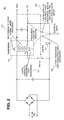
- Figure 2 is a schematic of a power supply 201, which expands on the outline schematic of Figure 1 by representing the parasitic capacitances 209 that exist between the transformer core and electrical earth, the parasitic capacitances 211 that exist between the input and output windings and the transformer core and also the parasitic capacitances 213 that exist between the input and output windings of the transformer.
- the transformer core is the ferrite core used in the transformer construction to provide a low reluctance path for the magnetic flux coupling input and output windings of the transformer 207.
- the parasitic capacitance 215 between the output of the transformer and electrical earth in some cases maybe be short circuited depending on the application and or the way in which the electrical noise measurements are made.
- the voltages across both input and output windings of the transformer 207 transition in accordance with the standard flyback power supply operation. These transitions generate displacement currents in the electrical earth through the various parasitic capacitances 209, 211, 213 and 215 shown. These displacement currents are detected as common mode noise (or emissions) and measured by a piece of test equipment called a Line Input Stabilization Network (LISN). The configuration and connection of this equipment is well documented and known to one skilled in the art.
- LSN Line Input Stabilization Network
- FIG. 2 also highlights capacitor Cy 217 which is a Y-capacitor, that is commonly used in switching power supplies to reduce the common mode emissions.
- This component, capacitor Cy 217 provides a low impedance path for displacement currents flowing between input and output windings of the transformer 207, to return to their source without flowing through electrical earth. The currents in capacitor Cy 217 are not detected by the LISN and its use therefore acts to reduce common mode emissions.
- An energy transfer element having an energy transfer element input winding and an energy transfer element output winding is disclosed.
- the energy transfer element input winding is capacitively coupled to the energy transfer element output winding.
- the energy transfer element is capacitively coupled to electrical earth.
- One or more additional windings are introduced as part of the energy transfer element.
- the one or more additional windings substantially reduce capacitive displacement current between the energy transfer element input winding and energy transfer element output winding by balancing the relative electrostatic fields generated between these windings and/or between the energy transfer element and electrical earth by canceling the electrostatic fields generated by all windings within the energy transfer element relative to electrical earth through the selection of the physical position and number of turns in the additional windings.
- Embodiments of methods and apparatuses for reducing electrical earth displacement current flow generated by wound components are disclosed.
- numerous specific details are set forth in order to provide a thorough understanding of the present invention. It will be apparent, however, to one having ordinary skill in the art that the specific detail need not be employed to practice the present invention. In other instances, well-known materials or methods have not been described in detail in order to avoid obscuring the present invention.
- This invention specifically deals with the reduction in common mode noise generated by the energy transfer element, commonly referred to as the power supply transformer, during the operation of a switching power supply.
- Various embodiments of the present invention described in herein provide techniques that are used in the construction of a transformer to substantially reduce the electrical earth currents generated by the power supply allowing the system cost to be reduced either by eliminating the requirement to use a Y-capacitor or by reducing the value of Y capacitor necessary. Reducing the value of or eliminating the Y capacitor also reduces leakage currents between the safety isolated output and the AC input line. This is advantageous in applications where the output can come in contact with the user such as for example but not limited to cellular phone applications or the like.
- various embodiments of the techniques described herein substantially reduce the capacitive displacement currents that normally flow in a switching power supply between the primary and secondary windings, and the core of the transformer and electrical earth.
- the reduction is achieved with the addition of windings in the transformer.
- the number of turns of these additional windings are specifically selected based on the main winding rums to cancel and balance differential electrostatic fields generated by the main windings.
- These displacement currents normally require that extra measures, such as for example in the form of external components, are taken in the design of the switching power supply to avoid these displacement currents interfering with other equipment.
- Various embodiments of the present invention therefore reduce system cost by eliminating certain power supply components that would otherwise be necessary to a designer not having the benefit of this disclosure.
- displacement currents generated by the operation of a switching power supply and flowing to electrical earth are measured as electrical noise, also known as common mode emissions, that can cause electromagnetic interference (EMI) to other equipment. It is therefore necessary to maintain these currents below published limits set up by regulatory bodies globally.
- Transformers in switching power supplies generate displacement current flow to electrical earth in two ways.
- One of the ways is the flow of displacement current between the core of the transformer and electrical earth. This current is generated by voltage transitions on the transformer windings coupling capacitively to the core of transformer. This current then flows capacitively through free space between the core of the transformer and electrical earth.
- Various embodiments of the present invention describe the use of one or more additional windings within the transformer construction that employ the natural voltage fluctuations of the transformer windings to balance and cancel the relative electrostatic fields between the input and output windings that arise during the switching power supply operation.
- the design of these additional windings is specific to a particular transformer both in terms of the number of turns used and their physical positioning.
- Figure 3A shows a simple outline schematic of a transformer 301.
- the two ends of the input winding 303 are labeled nodes A and B.
- the two ends of the output winding 305 are labeled nodes C and D.
- the physical core 307 of the transformer is labeled as a further node E.
- the dot polarity of the windings 303 and 305 is such that when there is a voltage transition on the input winding 303 such that node B is becoming more positive relative to node A, the voltage of node D will increase relative to node C.
- these voltage transitions generate displacement currents in the parasitic capacitances resulting in current flowing to electrical earth.
- additional windings are provided in one embodiment of the present invention to substantially reduce these electrical earth currents.
- a winding technique is used to reduce displacements currents between the transformer windings 303 and 305 and transformer core 307.
- one of the windings 303 or 305 is normally in closer proximity to the transformer core 307 than the other.
- one of the windings 303 or 305 typically has higher voltage transitions across it.
- Figure 3B shows the typical cross section of a layer wound flyback transformer 301 where node B of input winding 303 is wound closest to the transformer core 307.
- the output winding 305 is wound outside the input winding 303 and therefore has less influence on the generation of displacement currents between windings 303 and 305 and transformer core 307 since it is physically further from the transformer core 307.
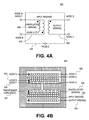
- Figure 4A shows the schematic of one embodiment of a transformer 401 wound with a cancellation winding 409 coupled to the primary input winding 403 since the placement of the primary input winding 403 in this case has most influence on the winding to transformer core 407 displacement current.
- Figure 4B shows the cross section of one embodiment of the transformer 401 with cancellation winding 407 between Nodes F and G. As shown in the depicted embodiment, Node F is connected to node A and Node G is left uncoupled electrically. In one embodiment, the dot polarity of the cancellation winding 409 is such that its electrostatic field opposes that created by the input winding 403.
- the exact choice of the number of turns used in this cancellation winding 409 is determined based on empirical optimization techniques.
- the variables considered include the percentage of the overall primary winding voltage seen by the first layer of the primary input winding 403, which is 33% in the embodiment illustrated in Figure 4b since there are 3 layers.
- the first layer of the input winding 403 is now further from the transformer core 407 due to the presence of the cancellation winding 409, its electrostatic field is weaker at the transformer core 407.
- the cancellation winding 407 typically requires fewer turns than the first layer of the input winding 403 to provide cancellation.
- the exact cancellation is more complex since there are lesser influences from all windings 403, 445 and 409, hence the reason that empirical techniques provide an effective optimization.
- the net effect is that the influence of the electrostatic field produced by the other windings in the transformer construction relative to the transformer core 407 are cancelled by the electrostatic field created by the cancellation winding 409. Consequently the displacement current between transformer windings and transformer core is theoretically zero if the electrostatic fields perfectly cancel. In practice, the effect is to substantially reduce the net displacement current.
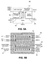
- FIG. 5A shows the schematic of a transformer 501 having this additional winding which is referred to as a balancing winding 511 since its net effect is to balance the electrostatic fields generated between input and output windings 503 and 505 of the transformer 501.
- the transformer 501 of Figure 5A and the cross section of transformer 501 illustrated in Figure 5B show the balance winding 511 in conjunction with the cancellation winding 509 described above.
- the balancing winding 511 between nodes H and I is shown coupled to the input winding 503 with the dot polarity such that the node H is connected to node A.
- a cross section of transformer 501 is shown with the inclusion of the balancing winding 511.
- balancing winding 511 is connected to the output winding 505, as is the case with an embodiment described below, depending on which of the windings is the prime generator of the displacement current.
- the output winding 505 could be seen as the prime generator in which case, the optimum connection of the balancing winding 511 could be by coupling to the output winding 505.
- the primary input winding 503 is assumed to be the prime generator and as such, the additional balance winding 511 is designed to oppose the electrostatic field generated by the input winding 503.
- the number of turns are selected such that the net electrostatic field from the combination of the balancing and input windings 511 and 503, exactly matches that generated by the output winding 505.
- the differential field between primary and secondary circuits is zero and the displacement current is also zero.
- the effect is to substantially reduce the net displacement current
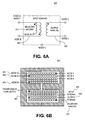
- Figure 6A is a schematic diagram of transformer 601 wound with a balancing winding 611
- Figure 6B shows a cross section of transformer 601 with balancing winding 611 in accordance with the teachings of the present invention.
- the balancing winding 611 is positioned outside the output winding 605 in the construction of the transformer 601.
- the dot polarity of balancing winding 611 is such that it opposes the electrostatic field generated by the input winding 603 relative to the output winding 605.
- Node D of the output winding 605 is positioned to reduce the relative electrostatic field between the main input winding 603 and the output winding 605.
- the input winding 603 has 3 layers and therefore 33% of the voltage across the primary input winding 603 is seen in the outer most layer next to the output winding 605. Since, in a typical design, the output winding 605 has fewer turns than the outer layer of the primary input winding 603, the input winding 603 is the primary generator of displacement current.
- Node G opposes the electrostatic field generated by the input winding 603. The correct choice of number of turns therefore substantially reduces the net displacement current between input and output windings 603 and 605.
- the position of the balancing winding 611 on the outside of the other windings in the transformer construction also means that its electrostatic field opposes that of the input winding 603 relative to the physical core 607 of the transformer 601.
- the balancing winding 611 in this embodiment also provides a degree of cancellation of capacitively coupled displacement current through free space between the core of the transformer and electrical earth, previously provided by the separate cancellation winding 409 of Figure 4.
- This single winding technique also provides the advantage of reducing the leakage inductance between the input and output windings 603 and 605 since these two windings are physically closer in the transformer construction.
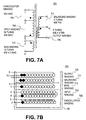
- FIGs 7A shows specific details of a schematic and cross section of one embodiment of a transformer 701 using the techniques described above in accordance with the teachings of the present invention.
- Figure 7B shows a cross-section of one embodiment of transformer 701 in accordance with the teachings of the present invention.
- This design of transformer 701 has a cancellation winding 709 between the main input winding 703 (primary) and the transformer core 707.
- this design uses a bias winding 713 as the low voltage supply for the power supply switching regulator circuitry coupled to the input winding 703.
- the balancing winding 711 in this case is coupled to the output winding 705 since, in this particular design, the output winding 705 is the primary generator of common mode displacement currents flowing between the primary and secondary input and output windings 703 and 705. According to the description above therefore, this coupling of the balancing winding 711 provides the optimum performance.
- Tables I, II, III and IV below summarize the electrical specifications, materials, winding instructions and winding circuit connections associated with one embodiment of transformer 701 in accordance with the teachings of the present invention. Electrical Specifications. Electrical Strength 60Hz 1 minute, from Pins 1-5 to Pins 6-10 3000 Vac Creepage Between Pins 1-5 and Pins 6-14 6-2 mm (Min.) Primary Inductance All windings open 980 uH +/- 10% Resonant Frequency All windings open 500 KHz (Min.) Primary Leakage Inductance Pins 6-10 shorted 35 uH Materials.
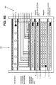
- FIG 8A shows specific details of a schematic of one embodiment of a transformer 801 using the techniques described above in accordance with the teachings of the present invention.
- Figure 8B shows a cross-section of one embodiment of transformer 801 in accordance with the teachings of the present invention.
- the construction of transformer 801 has a cancellation winding 804 and a primary balancing winding 802 in addition to a secondary balancing winding 803.
- transformer 801 includes multiple output windings 805, which are interleaved to improve regulation of each output voltage relative to the other outputs, a technique that will be known to one skilled in the art.
- the use of a secondary balancing winding 803 in addition to the primary balancing winding 802, is particularly useful, though is not restricted to, the construction of transformers having multiple outputs such as that shown in Figures 8A and 8B, since the single winding nature of the secondary balancing winding 803 provides a relatively uniform voltage gradient from one end of the winding to the other.
- this secondary balancing winding 803 were not present, the voltage gradient from one end of the multiple secondary windings 805 is less uniform since it is constructed of a number of different output voltage windings, which are interleaved and therefore do not necessarily start at one side of transformer winding region 806 and finish at the other side of winding region 806.
- the choice of the number of turns of the primary balancing winding 802 and secondary balancing winding 803 may be chosen to reduce the relative electrostatic fields between these windings and therefore reduce the displacement currents flowing between windings 802 and 803 in accordance with the teachings of the present invention.
Landscapes
- Engineering & Computer Science (AREA)
- Power Engineering (AREA)
- Dc-Dc Converters (AREA)
- Coils Or Transformers For Communication (AREA)
- Coils Of Transformers For General Uses (AREA)
- Rectifiers (AREA)
Applications Claiming Priority (2)
| Application Number | Priority Date | Filing Date | Title |
|---|---|---|---|
| US774275 | 1996-12-27 | ||
| US10/774,275 US6995990B2 (en) | 2001-03-08 | 2004-02-06 | Method and apparatus for substantially reducing electrical earth displacement current flow generated by wound components |
Publications (2)
| Publication Number | Publication Date |
|---|---|
| EP1562204A2 true EP1562204A2 (de) | 2005-08-10 |
| EP1562204A3 EP1562204A3 (de) | 2012-04-25 |
Family
ID=34679406
Family Applications (1)
| Application Number | Title | Priority Date | Filing Date |
|---|---|---|---|
| EP05250624A Withdrawn EP1562204A3 (de) | 2004-02-06 | 2005-02-04 | Verfahren und Vorrichtung zur wesentlichen Verminderung des durch Wicklungskomponenten verursachten elektrischen Erdverschiebungsstromflusses |
Country Status (3)
| Country | Link |
|---|---|
| US (3) | US6995990B2 (de) |
| EP (1) | EP1562204A3 (de) |
| JP (1) | JP4689290B2 (de) |
Cited By (4)
| Publication number | Priority date | Publication date | Assignee | Title |
|---|---|---|---|---|
| CN103093936A (zh) * | 2011-11-02 | 2013-05-08 | 施耐德电器工业公司 | 变压器及其绕制方法 |
| CN103310956A (zh) * | 2012-03-06 | 2013-09-18 | 台达电子企业管理(上海)有限公司 | 一种可抑制共模电流的变压器及其功率变换器 |
| CN106385185A (zh) * | 2016-09-27 | 2017-02-08 | 青岛海信电器股份有限公司 | 反激式开关电源及改善其电磁兼容性能的方法 |
| NL2019772B1 (en) * | 2017-10-20 | 2019-04-29 | Dutch Infinity Energy D I E B V | An electrical converter, a method and a computer program product |
Families Citing this family (12)
| Publication number | Priority date | Publication date | Assignee | Title |
|---|---|---|---|---|
| TWI306327B (en) * | 2005-12-30 | 2009-02-11 | System General Corp | An energy transfer device for reducing a conductivity electromagnetic interference and manufacturing method thereof |
| US7545656B2 (en) * | 2006-07-18 | 2009-06-09 | Comarco Wireless Technologies, Inc. | Common mode noise reduction circuit utilizing dual primary windings |
| US8154371B2 (en) * | 2008-11-06 | 2012-04-10 | Power Integrations, Inc. | Method and apparatus for adjusting displacement current in an energy transfer element |
| FI20100144A0 (fi) | 2010-04-09 | 2010-04-09 | Salcomp Oyj | Järjestely ja menetelmä kapasitiivisen virran vähentämiseksi |
| CN102163492B (zh) * | 2010-12-31 | 2013-05-29 | 崧顺电子(深圳)有限公司 | 一种无y电容的变压器及其制备方法 |
| US20140300440A1 (en) * | 2013-04-05 | 2014-10-09 | Hamilton Sundstrand Corporation | Inductor gap spacer |
| CN105099205B (zh) * | 2015-08-12 | 2017-12-26 | 矽力杰半导体技术(杭州)有限公司 | 开关电源、反激式变换器及变压器 |
| US9722499B2 (en) * | 2015-12-08 | 2017-08-01 | Power Integrations, Inc. | Energy transfer element with capacitor compensated cancellation and balance shield windings |
| JP6652841B2 (ja) * | 2016-01-19 | 2020-02-26 | 東芝テック株式会社 | 非接触受電装置 |
| US10141100B2 (en) * | 2017-03-24 | 2018-11-27 | Google Llc | Common-mode noise reduction |
| DE102017128989A1 (de) * | 2017-12-06 | 2019-06-06 | Wobben Properties Gmbh | Transformatoreinrichtung zum Übertragen von Oberwellen |
| KR102939988B1 (ko) * | 2021-03-03 | 2026-03-17 | 삼성전자 주식회사 | 전자 장치에서 터치 전류를 줄일 수 있는 전원 공급 장치 |
Family Cites Families (28)
| Publication number | Priority date | Publication date | Assignee | Title |
|---|---|---|---|---|
| US2553324A (en) * | 1949-07-27 | 1951-05-15 | Gen Electric | Wide band audio and video transformer |
| US3299384A (en) * | 1964-07-01 | 1967-01-17 | Ibm | Wide-band transformer having neutralizing winding |
| US3963975A (en) * | 1975-03-05 | 1976-06-15 | General Electric Company | Electromagnetically shielded electrical power supply with reduced common mode electromagnetic interference output |
| GB1539757A (en) * | 1975-06-11 | 1979-01-31 | Sony Corp | Transformers and converters including such transformers |
| JPS5847691Y2 (ja) * | 1978-04-13 | 1983-10-31 | 横河・ヒユ−レツト・パツカ−ド株式会社 | トロイダル状トランス |
| JPS5910044B2 (ja) * | 1979-07-05 | 1984-03-06 | 富士通株式会社 | 通信用変成器 |
| JPH046264Y2 (de) * | 1981-04-24 | 1992-02-20 | ||
| US4507721A (en) * | 1982-07-28 | 1985-03-26 | Nippon Telegraph & Telephone Public Corporation | DC-DC Converter for remote power feeding |
| US4518941A (en) * | 1983-11-16 | 1985-05-21 | Nihon Kohden Corporation | Pulse transformer for switching power supplies |
| JPS60226112A (ja) | 1984-04-25 | 1985-11-11 | Hitachi Ltd | トランスの巻線間シ−ルド構造 |
| US4707673A (en) * | 1986-06-10 | 1987-11-17 | Gulton Industries, Inc | Directional coupling transformer for bi-directional full duplex data bus |
| FR2606204A1 (fr) * | 1986-11-04 | 1988-05-06 | Grimaud Jacques | Transformateur audio-frequence a grande dynamique avec enroulement de neutralisation |
| US5150046A (en) * | 1990-12-17 | 1992-09-22 | Goldstar Electric Machinery Co. | Noise-shielded transformer |
| US5579020A (en) * | 1993-09-27 | 1996-11-26 | Sensis Corporation | Lightweight edge-slotted waveguide antenna structure |
| NO179348C (no) * | 1994-02-07 | 1996-09-18 | Labyrint Dev As | Anordning for levering av en höyfrekvent, pulserende likespenning på sekundærsiden av en transformator |
| US5440472A (en) | 1994-02-14 | 1995-08-08 | Powercube Corporation | Integrated magnetic power converter |
| US5615091A (en) * | 1995-10-11 | 1997-03-25 | Biochem International, Inc. | Isolation transformer for medical equipment |
| JPH1052036A (ja) | 1996-07-26 | 1998-02-20 | Toshiba Corp | スイッチング電源装置 |
| JP2002539619A (ja) * | 1999-03-09 | 2002-11-19 | コーニンクレッカ フィリップス エレクトロニクス エヌ ヴィ | 回路装置 |
| JP3892180B2 (ja) | 1999-09-28 | 2007-03-14 | 株式会社電研精機研究所 | 障害波遮断変成器 |
| JP2001345229A (ja) * | 2000-06-02 | 2001-12-14 | Yokogawa Electric Corp | スイッチングトランスのコイル構造 |
| US6366474B1 (en) * | 2000-09-29 | 2002-04-02 | Jeff Gucyski | Switching power supplies incorporating power factor correction and/or switching at resonant transition |
| US6549431B2 (en) * | 2001-03-08 | 2003-04-15 | Power Integrations, Inc. | Method and apparatus for substantially reducing electrical earth displacement current flow generated by wound components |
| US6903642B2 (en) * | 2001-12-03 | 2005-06-07 | Radian Research, Inc. | Transformers |
| US7119647B2 (en) * | 2001-12-21 | 2006-10-10 | Power Integrations, Inc. | Method and apparatus for substantially reducing electrical earth displacement current flow generated by wound components without requiring additional windings |
| US6714426B1 (en) * | 2002-11-04 | 2004-03-30 | Semtech Corporation | Multiple-phase, multi-module power supply system for high frequency operation |
| US6836415B1 (en) * | 2003-06-18 | 2004-12-28 | Systems General Corp. | Primary-side regulated pulse width modulation controller with improved load regulation |
| JP4482765B2 (ja) | 2005-09-30 | 2010-06-16 | Tdk株式会社 | スイッチング電源装置 |
-
2004
- 2004-02-06 US US10/774,275 patent/US6995990B2/en not_active Expired - Lifetime
-
2005
- 2005-02-04 EP EP05250624A patent/EP1562204A3/de not_active Withdrawn
- 2005-02-07 JP JP2005030763A patent/JP4689290B2/ja not_active Expired - Fee Related
- 2005-12-19 US US11/313,147 patent/US7236078B2/en not_active Expired - Fee Related
-
2007
- 2007-05-16 US US11/804,174 patent/US7355871B2/en not_active Expired - Fee Related
Cited By (7)
| Publication number | Priority date | Publication date | Assignee | Title |
|---|---|---|---|---|
| CN103093936A (zh) * | 2011-11-02 | 2013-05-08 | 施耐德电器工业公司 | 变压器及其绕制方法 |
| CN103093936B (zh) * | 2011-11-02 | 2016-06-08 | 施耐德电器工业公司 | 变压器及其绕制方法 |
| CN103310956A (zh) * | 2012-03-06 | 2013-09-18 | 台达电子企业管理(上海)有限公司 | 一种可抑制共模电流的变压器及其功率变换器 |
| US9129736B2 (en) | 2012-03-06 | 2015-09-08 | Delta Electronics (Shanghai) Co., Ltd. | Transformer capable of suppressing common mode current and power converter thereof |
| CN103310956B (zh) * | 2012-03-06 | 2016-03-23 | 台达电子企业管理(上海)有限公司 | 一种可抑制共模电流的变压器及其功率变换器 |
| CN106385185A (zh) * | 2016-09-27 | 2017-02-08 | 青岛海信电器股份有限公司 | 反激式开关电源及改善其电磁兼容性能的方法 |
| NL2019772B1 (en) * | 2017-10-20 | 2019-04-29 | Dutch Infinity Energy D I E B V | An electrical converter, a method and a computer program product |
Also Published As
| Publication number | Publication date |
|---|---|
| US7355871B2 (en) | 2008-04-08 |
| US20060092673A1 (en) | 2006-05-04 |
| EP1562204A3 (de) | 2012-04-25 |
| US20070222548A1 (en) | 2007-09-27 |
| US20040246749A1 (en) | 2004-12-09 |
| JP4689290B2 (ja) | 2011-05-25 |
| JP2005223343A (ja) | 2005-08-18 |
| US6995990B2 (en) | 2006-02-07 |
| US7236078B2 (en) | 2007-06-26 |
Similar Documents
| Publication | Publication Date | Title |
|---|---|---|
| US7564334B2 (en) | Method and apparatus for substantially reducing electrical earth displacement current flow generated by wound components | |
| US7355871B2 (en) | Method and apparatus for substantially reducing electrical earth displacement current flow generated by wound components | |
| US7378929B2 (en) | Method and apparatus for substantially reducing electrical displacement current flow between input and output circuits coupled to input and output windings of an energy transfer element | |
| US7567162B2 (en) | Apparatus and method for winding an energy transfer element core |
Legal Events
| Date | Code | Title | Description |
|---|---|---|---|
| PUAI | Public reference made under article 153(3) epc to a published international application that has entered the european phase |
Free format text: ORIGINAL CODE: 0009012 |
|
| AK | Designated contracting states |
Kind code of ref document: A2 Designated state(s): AT BE BG CH CY CZ DE DK EE ES FI FR GB GR HU IE IS IT LI LT LU MC NL PL PT RO SE SI SK TR |
|
| AX | Request for extension of the european patent |
Extension state: AL BA HR LV MK YU |
|
| 17P | Request for examination filed |
Effective date: 20050810 |
|
| RAP3 | Party data changed (applicant data changed or rights of an application transferred) |
Owner name: POWER INTEGRATIONS, INC. |
|
| PUAL | Search report despatched |
Free format text: ORIGINAL CODE: 0009013 |
|
| PUAF | Information related to the publication of a search report (a3 document) modified or deleted |
Free format text: ORIGINAL CODE: 0009199SEPU |
|
| PUAL | Search report despatched |
Free format text: ORIGINAL CODE: 0009013 |
|
| AK | Designated contracting states |
Kind code of ref document: A3 Designated state(s): AT BE BG CH CY CZ DE DK EE ES FI FR GB GR HU IE IS IT LI LT LU MC NL PL PT RO SE SI SK TR |
|
| AX | Request for extension of the european patent |
Extension state: AL BA HR LV MK YU |
|
| RIC1 | Information provided on ipc code assigned before grant |
Ipc: H02M 3/335 20060101ALI20120307BHEP Ipc: H01F 38/42 20060101ALI20120307BHEP Ipc: H01F 27/38 20060101AFI20120307BHEP |
|
| D17D | Deferred search report published (deleted) | ||
| AK | Designated contracting states |
Kind code of ref document: A3 Designated state(s): AT BE BG CH CY CZ DE DK EE ES FI FR GB GR HU IE IS IT LI LT LU MC NL PL PT RO SE SI SK TR |
|
| AX | Request for extension of the european patent |
Extension state: AL BA HR LV MK YU |
|
| RIC1 | Information provided on ipc code assigned before grant |
Ipc: H02M 3/335 20060101ALI20120316BHEP Ipc: H01F 38/42 20060101ALI20120316BHEP Ipc: H01F 27/38 20060101AFI20120316BHEP |
|
| AKX | Designation fees paid |
Designated state(s): DE FR GB IT NL SE |
|
| STAA | Information on the status of an ep patent application or granted ep patent |
Free format text: STATUS: THE APPLICATION IS DEEMED TO BE WITHDRAWN |
|
| 18D | Application deemed to be withdrawn |
Effective date: 20150901 |