US4707673A - Directional coupling transformer for bi-directional full duplex data bus - Google Patents
Directional coupling transformer for bi-directional full duplex data bus Download PDFInfo
- Publication number
- US4707673A US4707673A US06/872,546 US87254686A US4707673A US 4707673 A US4707673 A US 4707673A US 87254686 A US87254686 A US 87254686A US 4707673 A US4707673 A US 4707673A
- Authority
- US
- United States
- Prior art keywords
- data bus
- directional coupler
- data
- winding means
- winding
- Prior art date
- Legal status (The legal status is an assumption and is not a legal conclusion. Google has not performed a legal analysis and makes no representation as to the accuracy of the status listed.)
- Expired - Fee Related
Links
Images


Classifications
-
- H—ELECTRICITY
- H03—ELECTRONIC CIRCUITRY
- H03H—IMPEDANCE NETWORKS, e.g. RESONANT CIRCUITS; RESONATORS
- H03H7/00—Multiple-port networks comprising only passive electrical elements as network components
- H03H7/48—Networks for connecting several sources or loads, working on the same frequency or frequency band, to a common load or source
Definitions
- the field of the present invention relates generally to coupling transformers for data buses, and more specifically relates to such transformers for providing bi-directional communication along a data bus of units coupled thereto.
- Coupling systems for permitting a number of receiver/transmitter units to communicate along a common data bus are well known in the art.
- telephony hybrid transformers are used along a telephone systems cable lines in a two-wire communication system for providing directional coupling between telephone sets.
- the hybrid transformers typically used in telephony provide bi-directional communication if two terminals in the communication system are connected at the far ends of a common cable.
- a third terminal is connected to the communication line between the other two terminals at the extremes of the cable, and the other two terminals are each simultaneously transmitting signals down the line in opposite directions, the third terminal will receive a signal that is a mixture of the signals being transmitted by the other two terminals, and as a result will be unable to decipher or receive information from either of the other two terminals unless the signals are time displaced, phase displaced, or in some other way made electrically different to permit detection by a third terminal from the common transmission line.
- the typical telephony hybrid couplers must have a balanced network to operate in proper termination, whereby if along a common telephone cable an open circuit or short circuit occurs, the telephony hybrid couplers cannot provide communication for terminals connected to the cable system upstream of the failure point in the cable.
- Directional couplers are also known in the art for use in microwave transmission systems.
- microwave directional couplers by necessity use wave guide techniques that are not practical in the frequency range of 100 KHz to 10 MHz, where coaxial cables or twisted shielded cables serve as the transmission media or data bus for data signals.
- An object of the invention is to permit data signals to be simultaneously transmitted in opposite directions along a common transmission cable or data bus, while permitting remote units and a main unit coupled to the transmission line or data bus to receive one of the signals without interference from the other signal on the line, or to transmit one of the signals without interference with the other signal on the line.
- Another object of the invention is to provide communication in the half-duplex mode between terminals or remote units located upstream of a failure point along a transmission line or data bus.
- Another object of the invention is to provide a bi-directional coupling transformer for permitting data to be bi-directionally transmitted along a data bus in the frequency range of 100 KHz to about 10 MHz, between a master unit and remote units connected to the data bus.
- Another object of the invention is to provide a bi-directional coupling transformer for permitting the bi-directional transfer of data between a plurality of terminals connected to a data bus, with very low signal loss.
- the present invention includes coupling transformer means for coupling individually the transmitting and receiving subsystems of a communication unit to a data bus, in a multi-unit system, wherein for each receiving or transmitting unit the bi-directional coupling transformer means further includes first and second ports which are connected to the transmission line, and a winding means for connection to the appropriate receiving or transmitting unit of the communication units to be coupled to the data bus or transmission line.
- the present invention includes bi-directional coupling transformer means including a common toroid core, a first winding for connection between the two conductors of a data bus or transmission line, second and third windings for connection in series with the two individual conductors of the data bus or transmission line, respectively, and a fourth winding for connection to a data communication unit, whereby individual ones of the directional coupling transformer means are similarly provided for connecting each one of the communicators or units in the data communication system to the data bus or transmission line, thereby providing for bi-directional data communication between the individual communication units connected to the data bus, each one of the units being either a data transmitter or data receiver.
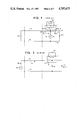
- FIGS. 1 and 2 show schematic diagrams of typical telephony hybrid circuits connected in a transmitting mode of operation, and alternatively in a receiving mode of operation, respectively;
- FIG. 3 shows a block diagram of three stations in typical connection to a transmission or data bus line
- FIG. 4 shows a typical circuit schematic diagram for a MIL-STD-1553B data bus interfaces
- FIG. 5 shows a circuit schematic diagram of one embodiment of the present invention included in a data bus interface circuit
- FIG. 6 shows an equivalent circuit schematic diagram of the one embodiment of the invention of FIG. 5;
- FIG. 7 shows a circuit schematic diagram of another embodiment of the invention included in a data bus transmission system for connecting transmitting and receiving units to the system for bi-directional communication in the system;
- FIG. 8 shows a block schematic diagram of yet another embodiment of the invention for a bi-directional full duplex data bus system
- FIG. 9 shows a circuit schematic diagram of a coupling transformer for one embodiment of the invention.
- FIG. 10 shows the mechanical construction for winding a coupling transformer for another embodiment of the invention.
- FIG. 11 shows a later fabrication step for producing the transformer of FIG. 10.
- FIGS. 1 and 2 showing hybrid circuits for use as typical telephone hybrid couplers, wherein the hybrid transformer 1 includes two windings 3 and 5, with winding 5 being a centertapped winding having a tap at connection point 7.
- a transmitter 9 is operated to produce a signal voltage V T , as shown.
- V T signal voltage
- a current I 1 will flow in the direction of arrow 15 through a conductor 11 of a transmission cable, a load impedance 17, and through another conductor 13 of the transmission cable back to the transmitter 9.
- signal current I 1 in this example also flows through the one-half of winding 5.
- transmitter 9 producing a signal voltage V T causes a current I 2 to flow in the opposite direction of I 1 , as shown by arrow 25.
- Current I 2 flows through resistor 19, the other half of the centertapped winding 5, through a balance resistor 21, and then returns to the transmitter 9 via conductor 13 of the transmission cable.
- the impedance of a receiving unit is represented by the resistor 23. Assume that any current flow through the receiver impedance 23 is designated as I 3 .
- transmitted signal current I 1 will be equal to the magnitude of the oppositely flowing signal current I 2 , causing the current I 3 at the receiver load impedance 23 to be equal to zero. In other words, no current will flow through the receiver load. Since the transmitted signal current is divided equally between the cable termination or equivalent resistance or impedance 17, and balance resistor 21, the loss of the illustrated hybrid transformer is 3 dB.
- the power delivered into the hybrid circuit 1 will then divide equally between the resistor 19 and the receiver resistance 23, thereby again producing a loss of 3 dB.
- the hybrid transformer or circuit 1 is functionally limited, in that if more than two Stations are connected to the transmission cable 11, 13, as shown in FIG. 3 (Stations A, B, and C referenced as items 10, 12, 14, respectively, are shown connected to the transmission cable 11, 13), and if Stations A and B, for example, transmit simultaneously, Station C will receive a mixed signal of the transmitted signals from Stations A and B, assuming the hybrid transformer 1 is in use for connecting the stations to the transmission cable 11, 13, thereby preventing Station C from receiving either message in an intelligible manner.
- MIL-STD-1553B data bus interfaces 31 are connected as shown in FIG. 4 to a data bus 33, whereby the data bus or cable 33 is terminated at both ends by its characteristic impedance Z 0 represented by resistors 35 and 37.
- Each interface 31 includes resistors 32 and a transformer 36.
- a master unit 39 (known as an MU) is connected at the left-hand side of the cable 33.
- a problem with the interfaces 31 is that any failures in the system such as a shorted interface, or a short in the cable at some point, will cause the entire data bus represented by the transmission cable 33 to become unstable. For example, ports or connection points upstream of a short in the data bus or cable 33 will not operate properly because of multiple reflections of electrical signals on the line caused by the short.
- the present invention provides in one embodiment, as shown in FIG. 5, a directional coupling transformer 41, that overcomes the problems discussed above in telephony and MIL-STD-1553B transmission coupling systems.
- the present invention includes a directional transformer 41 having four windings 43, 45, 47, and 49, in this example wound about a ferrite toroid core 51.
- this unique combination provides for two "port" coupling of the inventive transformer 41 to the data bus or transmission linen 53, 55.
- Winding 45 is connected between terminals 57 and 59, for providing Port 1, for connection to cable data bus conductors 53, 55, respectively, as shown.
- Windings 43 and 49 are connected between terminals 57 and 61, and terminals 59 and 63, respectively, as shown. Each winding 43, 49, has N 1 /2 turns, the sum of which is N 1 turns.
- the fourth winding 47 provides either an output voltage for a reception of a transmitted signal from either Station A or Station B, or for transmitting a signal to the stations, as will be discussed below. Winding 47 has N 3 turns. As shown in FIG. 5, Stations A and B are each transmitting signals represented by arrows 65 and 67, respectively, towards the directional coupler 41 at Station C.
- the relative polarity of current sensing windings 43 and 49 to voltage winding 45 as connected in the directional coupler 41, will determine whether the received data signal voltage V o developed across resistor 71 is representative of the transmitted signal from Station A or from Station B.
- a switching circuit can be installed in the directional coupler 41 for permitting selection of the polarities of windings 43 and 49, relative to winding 45, for receiving either the transmitted signal from Station A or from Station B, at Station C. With Station C in the receive mode, the received signal is represented by V 0 at terminals 73 and 75 of the directional coupler 41.
- impedances 77 and 79 each have an impedance equal to Z o ohms, which is the characteristic impedance of the cable 53, 55 or data bus 53, 55.
- Winding 45 having N 2 turns, is terminated or connected to the transmission cable or data bus 53, 55 via two resistors 81, in this example, each having a resistance designated by R 2 /2 ohms (each resistor 81, in this example, represents half of the resistance of a resistor value of R 2 ohms).
- Resistor 71 has a resistance value of R 3 ohms.
- the equivalent circuit for the directional coupler circuit of FIG. 5 is shown in FIG. 6.
- the equivalent circuit permits simpler analysis of the relative circuit parameters required ot obtain a desired operational characteristic or characteristics for the present directional coupler 41.
- the inventors provide a very detailed analysis of the present directional coupler circuit in a paper entitled "New Data Bus Interface Technique", published on June 18, 1985, in the IEEE Transactions on Aerospace and Electronic Systems, Vol. AES-21, No. 3, May 1985.
- the transmitting voltage signal therefrom is applied across terminals 73 and 75 (across winding 47).
- the transmitted signal will be induced into winding 45 (the voltage winding), which winding will produce two directional currents, one flowing to the left toward impedance 77 and the other flowing to the right toward impedance 79, in conductors 53, for example.
- a portion of the transmitted signal will be induced into the current winding 85, which winding will only produce current flowing in one direction, whereby the current winding 85 induced current cancels one of the currents produced by the voltage winding 83. In this manner, a uni-directional transmission current is produced.
- the selection of the transmission direction is determined by the relative polarities of the current windings 43 and 49, to the voltage winding 45. Also, if the previously mentioned transformer turns ratio and impedance ratio are as indicated, when Station C is in a receiving mode, the received signal voltage developed across the resistor 71 (also across winding 47) is made insensitive to cable terminations or reflections occurring along the data bus or transmission cable 53, 55.
- a pair of directional couplers 41 can be included along a data bus or cable 53, 55 for permitting a transmitter unit 89 and receiver unit 91 to be coupled to the data bus cable 53, 55.
- the directional coupling transformers 41 provide for the transmitter to transmit a data signal, for example, in the direction of arrow 93 down the data bus cable 53, 55, while simultaneously permitting transmitted signals to flow down the data bus cable 53, 55 from the extreme right-hand portion of the bus 53, 55, and other data signals to flow from the extreme left-hand portion of the data bus 53, 55 in the direction of arrow 95, whereby a portion of these data signals are received by the receiver 91 via its associated directional coupler 41, as indicated by the arrow 97.
- the use of the present directional coupling transformers 41 can be further extended from the use shown in FIG. 7, whereby as shown in FIG. 8 such directional coupling transformers 41 are used for coupling a Master Unit (MU) 101 including a transmitting unit 103 and receiving unit 105, and a plurality of N remote units 107 to the data bus cable 53, 55, where N is an integer number 1, 2, 3 . . . , n, for permitting the bi-directional flow of data along the data bus cable 53, 55 as shown by the arrows 109, 111.
- MU Master Unit
- N is an integer number 1, 2, 3 . . . , n
- communication would be between the MU 101 and the RU's 107.
- a cable having an impedance of 70 ohms was used, and the coupling transformers were constructed by using ferrite toroid cores.
- the termination at the far end of the cable was varied to be either open circuited, short circuited, or terminated to a 70 ohm resistor.
- the output waveforms from the directional coupling transformers, and the effects on the signals being carried by the cable, were monitored for each cable termination mode. It was observed that the waveforms developed were substantially constant regardless of the termination conditions at the far end of the cable, confirming the operation of the present directional coupler 41. Also, from the mathematical analysis of the directional coupler (See FIG.
- resistors 81 it was determined that, as the value of resistors 81 was increased from 100 ohms to 6,000 ohms, lower insertion losses and better impedance matching were obtained for the higher resistance values. However, it was also determined that higher values of resistance for resistors 81 necessitates the use of a higher turns ratio for the number of turns N 2 of winding 45 to the sum of turns (N 1 ) of the current windings 43 and 49, respectively, thereby resulting in increased winding capacitance in the voltage winding 45, which reduces the bandwidth of the coupling transformer 41.
- FIG. 9 A circuit schematic diagram of the present directional coupling transformer 41 is shown in FIG. 9, and represents the configuration or circuit used by the present inventors for engineering prototypes.
- the windings 43, 45, 47, and 49 are in this example wound around a ferrite toroid core 51, as shown.
- a toroid core 51 is preferred, other types of transformer cores can be utilized.
- winding 43 terminates at terminals 109 and 111
- winding 45 at terminals 113 and 115
- winding 49 at terminals 117 and 119
- winding 47 has its extreme ends terminated at terminals 121 and 125, and a centertap at terminal 123.
- the present coupling transformer 41 provides for bi-directional communication between units connected to a data bus or transmission cable without regard to cable termination. It also provides for the elimination of false output signals along the data bus or cable due to reflections caused by mismatching, thereby preserving the integrity of the true signal waveforms being conducted along the bus. In applications such as the data bussing for a multi-stage missile, the present invention permits bus operations to continue after staging without providing special termination hardware at the staging interface. Also, the present coupling transformer 41 has the additional advantage that no close matching or tuning is required when installing the coupling transformer 41 into a data bus system.
Abstract
Description
Claims (16)
Priority Applications (1)
| Application Number | Priority Date | Filing Date | Title |
|---|---|---|---|
| US06/872,546 US4707673A (en) | 1986-06-10 | 1986-06-10 | Directional coupling transformer for bi-directional full duplex data bus |
Applications Claiming Priority (1)
| Application Number | Priority Date | Filing Date | Title |
|---|---|---|---|
| US06/872,546 US4707673A (en) | 1986-06-10 | 1986-06-10 | Directional coupling transformer for bi-directional full duplex data bus |
Publications (1)
| Publication Number | Publication Date |
|---|---|
| US4707673A true US4707673A (en) | 1987-11-17 |
Family
ID=25359805
Family Applications (1)
| Application Number | Title | Priority Date | Filing Date |
|---|---|---|---|
| US06/872,546 Expired - Fee Related US4707673A (en) | 1986-06-10 | 1986-06-10 | Directional coupling transformer for bi-directional full duplex data bus |
Country Status (1)
| Country | Link |
|---|---|
| US (1) | US4707673A (en) |
Cited By (10)
| Publication number | Priority date | Publication date | Assignee | Title |
|---|---|---|---|---|
| US4998079A (en) * | 1990-01-16 | 1991-03-05 | Plessey Electronic Systems Corp. | Bi-directional signal coupler for a balanced data transmission line |
| US5081648A (en) * | 1990-03-12 | 1992-01-14 | The Boeing Company | Current mode data bus digital communications system |
| US5581710A (en) * | 1993-10-04 | 1996-12-03 | International Business Machines Corporation | Full duplex communication on a single communication ring |
| US5872944A (en) * | 1996-09-09 | 1999-02-16 | International Business Machines Corporation | Bus with request-dependent matching of the bandwidth available in both directions |
| US6314481B1 (en) * | 1999-01-19 | 2001-11-06 | Phoenix Logistics, Inc. | Resistance integrated coupler between databus and terminal device having databus windings with high resistance wire with resistance being 1.5 times databus cable nominal characteristic impedance |
| US20040066252A1 (en) * | 2001-10-31 | 2004-04-08 | Chominski Paul P. | Ninety degree coupler for radio frequency degraded circuits |
| US20040213021A1 (en) * | 2001-03-08 | 2004-10-28 | Odell Arthur B | Method and apparatus for substantially reducing electrical earth displacement current flow generated by wound components |
| US20040246749A1 (en) * | 2001-03-08 | 2004-12-09 | Odell Arthur B. | Method and apparatus for substantially reducing electrical earth displacement current flow generated by wound components |
| US20070129043A1 (en) * | 2005-12-01 | 2007-06-07 | General Instrument Corporation | Integrated balun and coupler transformer |
| US20080100396A1 (en) * | 2006-10-27 | 2008-05-01 | Harris Corporation, Corporation Of The State Of Delaware | Broadband hybrid junction and associated methods |
Citations (4)
| Publication number | Priority date | Publication date | Assignee | Title |
|---|---|---|---|---|
| US2734169A (en) * | 1956-02-07 | Douma | ||
| US4274051A (en) * | 1979-07-27 | 1981-06-16 | Bell Telephone Laboratories, Incorporated | Electromagnetic arrangement for measuring electrical current |
| US4467293A (en) * | 1981-09-18 | 1984-08-21 | Rockwell International Corporation | Ferrite type directional coupler |
| US4555681A (en) * | 1984-08-01 | 1985-11-26 | Westinghouse Electric Corp. | Improved, low-distortion, broadband directional coupler formed by multiple series transformers |
-
1986
- 1986-06-10 US US06/872,546 patent/US4707673A/en not_active Expired - Fee Related
Patent Citations (4)
| Publication number | Priority date | Publication date | Assignee | Title |
|---|---|---|---|---|
| US2734169A (en) * | 1956-02-07 | Douma | ||
| US4274051A (en) * | 1979-07-27 | 1981-06-16 | Bell Telephone Laboratories, Incorporated | Electromagnetic arrangement for measuring electrical current |
| US4467293A (en) * | 1981-09-18 | 1984-08-21 | Rockwell International Corporation | Ferrite type directional coupler |
| US4555681A (en) * | 1984-08-01 | 1985-11-26 | Westinghouse Electric Corp. | Improved, low-distortion, broadband directional coupler formed by multiple series transformers |
Cited By (26)
| Publication number | Priority date | Publication date | Assignee | Title |
|---|---|---|---|---|
| US4998079A (en) * | 1990-01-16 | 1991-03-05 | Plessey Electronic Systems Corp. | Bi-directional signal coupler for a balanced data transmission line |
| US5081648A (en) * | 1990-03-12 | 1992-01-14 | The Boeing Company | Current mode data bus digital communications system |
| US5581710A (en) * | 1993-10-04 | 1996-12-03 | International Business Machines Corporation | Full duplex communication on a single communication ring |
| US5872944A (en) * | 1996-09-09 | 1999-02-16 | International Business Machines Corporation | Bus with request-dependent matching of the bandwidth available in both directions |
| US6314481B1 (en) * | 1999-01-19 | 2001-11-06 | Phoenix Logistics, Inc. | Resistance integrated coupler between databus and terminal device having databus windings with high resistance wire with resistance being 1.5 times databus cable nominal characteristic impedance |
| US20060034101A1 (en) * | 2001-03-08 | 2006-02-16 | Odell Arthur B | Method and apparatus for substantially reducing electrical earth displacement current flow generated by wound components |
| US7355871B2 (en) | 2001-03-08 | 2008-04-08 | Power Integrations, Inc. | Method and apparatus for substantially reducing electrical earth displacement current flow generated by wound components |
| US20040246749A1 (en) * | 2001-03-08 | 2004-12-09 | Odell Arthur B. | Method and apparatus for substantially reducing electrical earth displacement current flow generated by wound components |
| US6894909B2 (en) * | 2001-03-08 | 2005-05-17 | Power Integrations, Inc. | Method and apparatus for substantially reducing electrical earth displacement current flow generated by wound components |
| US20050146902A1 (en) * | 2001-03-08 | 2005-07-07 | Odell Arthur B. | Method and apparatus for substantially reducing electrical earth displacement current flow generated by wound components |
| US6992903B2 (en) | 2001-03-08 | 2006-01-31 | Power Integrations, Inc. | Method and apparatus for substantially reducing electrical earth displacement current flow generated by wound components |
| US6995990B2 (en) | 2001-03-08 | 2006-02-07 | Power Integrations, Inc. | Method and apparatus for substantially reducing electrical earth displacement current flow generated by wound components |
| US7564334B2 (en) | 2001-03-08 | 2009-07-21 | Power Integrations, Inc. | Method and apparatus for substantially reducing electrical earth displacement current flow generated by wound components |
| US20060092673A1 (en) * | 2001-03-08 | 2006-05-04 | Odell Arthur B | Method and apparatus for substantially reducing electrical earth displacement current flow generated by wound components |
| US7164338B2 (en) | 2001-03-08 | 2007-01-16 | Power Integrations, Inc. | Method and apparatus for substantially reducing electrical earth displacement current flow generated by wound components |
| US20070080771A1 (en) * | 2001-03-08 | 2007-04-12 | Odell Arthur B | Method and apparatus for substantially reducing electrical earth displacement current flow generated by wound components |
| US20040213021A1 (en) * | 2001-03-08 | 2004-10-28 | Odell Arthur B | Method and apparatus for substantially reducing electrical earth displacement current flow generated by wound components |
| US7236078B2 (en) | 2001-03-08 | 2007-06-26 | Power Integrations, Inc. | Method and apparatus for substantially reducing electrical earth displacement current flow generated by wound components |
| US20070222548A1 (en) * | 2001-03-08 | 2007-09-27 | Odell Arthur B | Method and apparatus for substantially reducing electrical earth displacement current flow generated by wound components |
| US7276999B2 (en) | 2001-03-08 | 2007-10-02 | Power Integrations, Inc. | Method and apparatus for substantially reducing electrical earth displacement current flow generated by wound components |
| US20080007381A1 (en) * | 2001-03-08 | 2008-01-10 | Power Integrations, Inc. | Method and apparatus for substantially reducing electrical earth displacement current flow generated by wound components |
| US20040066252A1 (en) * | 2001-10-31 | 2004-04-08 | Chominski Paul P. | Ninety degree coupler for radio frequency degraded circuits |
| US20070129043A1 (en) * | 2005-12-01 | 2007-06-07 | General Instrument Corporation | Integrated balun and coupler transformer |
| US7856222B2 (en) * | 2005-12-01 | 2010-12-21 | General Instrument Corporation | Integrated balun and coupler transformer |
| US20080100396A1 (en) * | 2006-10-27 | 2008-05-01 | Harris Corporation, Corporation Of The State Of Delaware | Broadband hybrid junction and associated methods |
| US7403081B2 (en) * | 2006-10-27 | 2008-07-22 | Harris Corporation | Broadband hybrid junction and associated methods |
Similar Documents
| Publication | Publication Date | Title |
|---|---|---|
| EP0329912B1 (en) | Communication system for transmission of broadband and baseband information | |
| JP2722213B2 (en) | Matching device | |
| US4733389A (en) | Drop cable for a local area network | |
| US5659273A (en) | Line termination for multiple differential transmission lines | |
| US5301208A (en) | Transformer bus coupler | |
| US4357598A (en) | Three-phase power distribution network communication system | |
| US5095291A (en) | Communication filter for unshielded, twisted-pair cable | |
| CA1087258A (en) | Circuit for wire transmission of high frequency data communication pulse signals | |
| KR0180017B1 (en) | Circuit for broadband video transmission over unshielded twisted wire pairs | |
| US4707673A (en) | Directional coupling transformer for bi-directional full duplex data bus | |
| US3925728A (en) | Induction watthour meter for power systems transmitting carrier communication signals | |
| US5912924A (en) | Bidirectional channels using common pins for transmit and receive paths | |
| US5363068A (en) | Autotransformer capable of passing a DC signal as well as a balanced output signal | |
| EP0617560B1 (en) | Video adapter | |
| US4998079A (en) | Bi-directional signal coupler for a balanced data transmission line | |
| US5073762A (en) | Low frequency carrierband multi-port signal coupler | |
| US1812624A (en) | Telephone and telegraph signaling system | |
| EP0935865B1 (en) | Electrical data communications coupler with voltage and current mode transformer | |
| GB2185666A (en) | A data bus coupler | |
| WO2014207296A1 (en) | A method and device for transmitting' electrical power and data | |
| US5396197A (en) | Network node trap | |
| GB2176976A (en) | A data bus system | |
| Lee et al. | New data bus interface technique | |
| JP3191305B2 (en) | Information wiring equipment | |
| Hiroshima et al. | Proposals of coupling and decoupling network for immunity testing at telecommunication line ports |
Legal Events
| Date | Code | Title | Description |
|---|---|---|---|
| AS | Assignment |
Owner name: GULTON INDUSTRIES, INC., GULTON INDUSTRIAL PARK, E Free format text: ASSIGNMENT OF ASSIGNORS INTEREST.;ASSIGNORS:LEE, KYONG H.;MASCHHOFF, ROBERT H.;REEL/FRAME:004604/0834 Effective date: 19860714 |
|
| AS | Assignment |
Owner name: MARINE MIDLAND BANK, AS AGENT Free format text: SECURITY INTEREST;ASSIGNOR:GULTON INDUSTRIES, INC.;REEL/FRAME:004761/0969 Effective date: 19870416 |
|
| AS | Assignment |
Owner name: GULTON INDUSTRIES, INC. Free format text: RELEASED BY SECURED PARTY;ASSIGNOR:MARINE MIDLAND BANK, N.A., AS AGENT;REEL/FRAME:005041/0020 Effective date: 19880223 |
|
| FEPP | Fee payment procedure |
Free format text: PAYER NUMBER DE-ASSIGNED (ORIGINAL EVENT CODE: RMPN); ENTITY STATUS OF PATENT OWNER: LARGE ENTITY Free format text: PAYOR NUMBER ASSIGNED (ORIGINAL EVENT CODE: ASPN); ENTITY STATUS OF PATENT OWNER: LARGE ENTITY |
|
| REMI | Maintenance fee reminder mailed | ||
| LAPS | Lapse for failure to pay maintenance fees | ||
| FP | Lapsed due to failure to pay maintenance fee |
Effective date: 19911117 |
|
| STCH | Information on status: patent discontinuation |
Free format text: PATENT EXPIRED DUE TO NONPAYMENT OF MAINTENANCE FEES UNDER 37 CFR 1.362 |