EP1561990B1 - Schnellkupplung - Google Patents
Schnellkupplung Download PDFInfo
- Publication number
- EP1561990B1 EP1561990B1 EP05250553A EP05250553A EP1561990B1 EP 1561990 B1 EP1561990 B1 EP 1561990B1 EP 05250553 A EP05250553 A EP 05250553A EP 05250553 A EP05250553 A EP 05250553A EP 1561990 B1 EP1561990 B1 EP 1561990B1
- Authority
- EP
- European Patent Office
- Prior art keywords
- fluid coupling
- columns
- retainer
- ring
- axially
- Prior art date
- Legal status (The legal status is an assumption and is not a legal conclusion. Google has not performed a legal analysis and makes no representation as to the accuracy of the status listed.)
- Not-in-force
Links
Images


Classifications
-
- E—FIXED CONSTRUCTIONS
- E21—EARTH DRILLING; MINING
- E21B—EARTH DRILLING, e.g. DEEP DRILLING; OBTAINING OIL, GAS, WATER, SOLUBLE OR MELTABLE MATERIALS OR A SLURRY OF MINERALS FROM WELLS
- E21B10/00—Drill bits
- E21B10/44—Bits with helical conveying portion, e.g. screw type bits; Augers with leading portion or with detachable parts
-
- F—MECHANICAL ENGINEERING; LIGHTING; HEATING; WEAPONS; BLASTING
- F16—ENGINEERING ELEMENTS AND UNITS; GENERAL MEASURES FOR PRODUCING AND MAINTAINING EFFECTIVE FUNCTIONING OF MACHINES OR INSTALLATIONS; THERMAL INSULATION IN GENERAL
- F16L—PIPES; JOINTS OR FITTINGS FOR PIPES; SUPPORTS FOR PIPES, CABLES OR PROTECTIVE TUBING; MEANS FOR THERMAL INSULATION IN GENERAL
- F16L37/00—Couplings of the quick-acting type
- F16L37/08—Couplings of the quick-acting type in which the connection between abutting or axially overlapping ends is maintained by locking members
- F16L37/084—Couplings of the quick-acting type in which the connection between abutting or axially overlapping ends is maintained by locking members combined with automatic locking
- F16L37/098—Couplings of the quick-acting type in which the connection between abutting or axially overlapping ends is maintained by locking members combined with automatic locking by means of flexible hooks
- F16L37/0985—Couplings of the quick-acting type in which the connection between abutting or axially overlapping ends is maintained by locking members combined with automatic locking by means of flexible hooks the flexible hook extending radially inwardly from an outer part and engaging a bead, recess or the like on an inner part
- F16L37/0987—Couplings of the quick-acting type in which the connection between abutting or axially overlapping ends is maintained by locking members combined with automatic locking by means of flexible hooks the flexible hook extending radially inwardly from an outer part and engaging a bead, recess or the like on an inner part the flexible hook being progressively compressed by axial tensile loads acting on the coupling
-
- E—FIXED CONSTRUCTIONS
- E21—EARTH DRILLING; MINING
- E21B—EARTH DRILLING, e.g. DEEP DRILLING; OBTAINING OIL, GAS, WATER, SOLUBLE OR MELTABLE MATERIALS OR A SLURRY OF MINERALS FROM WELLS
- E21B7/00—Special methods or apparatus for drilling
- E21B7/02—Drilling rigs characterized by means for land transport with their own drive, e.g. skid mounting or wheel mounting
- E21B7/027—Drills for drilling shallow holes, e.g. for taking soil samples or for drilling postholes
Definitions
- This application relates to quick connector coupling assemblies of the type for connecting a male member formed at the end of a rigid tube in a hollow female body, and more particularly to quick connector coupling assemblies for high pressure applications.
- quick connectors In the automotive and other fields, one type of coupling assembly often utilized to provide a fluid connection between two components or conduits are quick connectors, which generally include a male member, or tube, received and retained in a female connector body.
- a quick connector is advantageous in that a sealed and secured fluid line may be established with minimum amount of time and expense.
- the connector body defines a conduit or passage in communication with the fluid system. It also defines a hollow internal shape to receive the tube end, in liquid tight sealing relation.
- the hollow shape within the body also houses a retainer within the hollow shape.
- the retainer is insertable through an entrance opening and is captured in a position to coact with a radial upset formed a given distance from the tube end to secure the tube in the body.
- the retainer must be configured to permit insertion through the entrance opening without damage and yet possesses sufficient strength to retain the integrity of the coupling under pressure.
- One type of retainer includes a plurality of locking arms which extend between a radially enlarged upset formed on the male member or tube and an annular radial face defined in the connector body inward of the entrance opening. The abutment of the retainer locking arms with the upset of the male member at one end and the annular radial face of the connector body at the other end prevents the withdrawal of the male member from the connector body.
- This type of retainer is prevalent in the art and has proven effective in many fluid line applications. Examples include U.S. Patent Nos. 5,161,832 ; 5,931,509 ; 5,324,082 ; and 5,626,371 .
- An 0-ring is sometimes used in with a quick connector to create a seal between the male member and the connector.
- the 0-ring is typically installed into the female body in a position to seal against the outer surface of the tube. In such a configuration, the 0-ring is located immediately axially inwardly of the retainer or separated by an annular spacer slidably mounted on the male member.
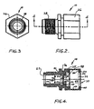
- FIG. 1 illustrates a fluid coupling 10 for high pressure applications in accordance to the present invention.
- the fluid coupling comprises a tubular male member 12, a hollow female connector body 14, a retainer 16 for securing the male member 12 within the connector body 14 and an O-ring or sealing member 18.
- the male member 12 is formed at the end of a hollow and rigid tube 20 which forms a part of a fluid line system.
- the tube 20 may lead to a component in a fluid line system, or may itself be a portion of a component in a fluid line system.
- the male member 12 includes a radially enlarged annular upset 22 formed at a given distance L 1 from the distal end.
- the male member 12 also includes a cylindrical portion 24 between the upset 22 and the distal end.
- the cylindrical portion 24 has a diameter approximately equal to the diameter of the tube 20.
- a portion of the male member 12, including the upset 22, may be coated with Nylon to provide corrosion protection. Alternatively, the coating may terminate outward from upset 22 to expose the metal surface of the upset 22 and the cylindrical portion 24.
- the female connector body 14 is illustrated in Figures 2-4 .
- the female connector body 14 has a hexagonal outer surface 26 at one end and a threaded outer surface 28 at the other end.
- the threaded outer surface 28 is adapted to mate with the corresponding threading and seat formed in a brake component or other high pressure fluid component.
- Such ports are described in SAE Standard J1290, Rev. Oct. 2002, published by the Society of Automotive Engineers, Inc., which is incorporated by reference herein.
- the end provided with threaded outer surface 28 terminates in an internal chamfer 29, shaped to seal on a conical surface formed within a port, for example, in a component of an automotive brake system such as a brake caliper or a brake system master cylinder.
- a component of an automotive brake system such as a brake caliper or a brake system master cylinder.
- the female connector body 14 is hollow and defines an axial bore 30 extending axially inwardly from an entrance 32.
- the bore 30 is divided into three portions: a retainer receiving portion 49, a sealing receiving portion 50 and a reduced diameter portion.
- the entrance 32 is defined by a radially inwardly extending rim 34 having an apex or entrance defining surface 36 and an axially inward annular load receiving face 38.
- the rim 34 is chamfered at the axially outward surface 40 to facilitate the insertion of the retainer 16 into the connector body 14.
- Axially inward from the rim 34 is a cylindrical surface 42.
- Axially inward from the cylindrical surface 42 is a cylindrical step 44 terminating at an annular surface 46.
- the annular face 38, the cylindrical surface 42, the cylindrical step 44, and the annular surface 46 define the retainer receiving portion 49 of the axial bore 30.
- Axially inward from the annular surface is a reduced diameter cylindrical bore 48 of the reduced diameter portion of the axial bore 30 defined by cylindrical surface 54.
- a radially outwardly groove or undercut 50 is formed on the surface 54 of the reduced diameter cylindrical bore 48 at a given distance L 2 between the annular surface 46 and the centerline of the groove 50.
- the groove is defined by two annular shoulders 52 equally spaced from the centerline of the groove, extending radially outwardly from the surface of the reduced diameter cylindrical bore 48 and a radially outwardly cylindrical surface 51 having a diameter D 4 .
- the shoulders 52 and the radially outwardly cylindrical surface 51 define the seal receiving portion of the axial bore 30.
- a radially inward extending annular rib 35 separates the seal receiving portion 50 from the retainer receiving portion of the axial bore 30.
- the width W of the groove 50 should be sized slightly larger than the un-deformed cross-section diameter D 1 of the O-ring 18 (see Figure 1 ) allowing the O-ring 18 to be retained axially in both directions between the shoulders 52 of the groove 50.
- the axially outwardly shoulder 52 absorbs the fluid pressure experienced by the O-ring.
- the depth (D 3 -D 4 )/2 of the groove 50 should be slightly smaller than the un-deformed cross-section diameter D 1 of the O-ring 18 allowing a portion of the O-ring 18 to extend radially inwardly beyond the un-grooved surface 54 of the reduced diameter cylindrical bore 48.
- the un-deformed inner diameter D 2 of the O-ring 18 is smaller than the diameter D 3 of the un-grooved surface 54 of the reduced diameter cylindrical bore 48. This assures that the O-ring 18 is able to create an effective seal between the connector body 14 and the male member 12.
- the distance L 2 between the center of the groove 50 and the annular surface 46 should be less than the distance L t between the distal end of the male member 12 and the center of the upset 22 (see Figure 1 ) to assure that the O-ring 18 surrounds the cylindrical portion 24 of the male member 12 once the male member 12 is fully inserted into the connector body 14.
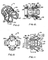
- the retainer 16 is illustrated in Figures 5-8 .
- the retainer 16 includes a cylindrical ring 56 at a first axial end.
- the ring 56 has a forward facing surface 58 and a rearward facing surface 60.
- a bore 62 is defined in the ring 56.
- Four locking members or wings 64 extend axially rearward or outward from the ring 56.
- the locking members 64 are detached from each other at a second axial end.
- Four axially extending elongated slots 66 are defined between each of the adjacent locking members 64 and extend from the second axial end to the ring 56.
- the slots 66 allow the locking members 64 to flex radially relative to the ring 56.
- the ring 56 has a conical outer surface 68 to facilitate the insertion of the retainer 16 into the connector body 14.
- Each locking member 64 includes two columns 70 with a radially outer surface 70a and a radially inner surface 70b.
- the outer surface 70a is coextensive with the outer surface of ring 56 rear connecting beam 72 connects the two columns 70 at the second axial end.
- the beams 72 define an axially outer or rearward edge 71 of the retainer columns 70 of adjacent locking members 64 define slots 66.
- the two columns 70, the ring 56, and the connecting beam 72 define, a window 74.
- Each locking member 64 further includes within the window 74, a duckbill shaped flexible locking arm 76 extending axially forward from the connecting beam 72 between the two columns 70. Since the arm 76 is only connected to the remainder of the locking member 64 at the connecting beam 72, the arm 76 is able to flex radially relative to the remainder of the locking member 64.
- Each arm 76 has a first, or front or forward abutment surface 78, a first ramped top surface 80, a second ramped top surface 82, a second, or rear or rearward abutment surface 84, a notch 86 defined on the ramped top surfaces 80,82, a ramped bottom surface 88, and a cylindrical flat bottom surface 90 that extends axially outwardly from said first abutment surface.
- the cylindrical flat bottom surfaces 90 of duck bill locking arms 76 collectively define an intermittent cylindrical surface having an inner diameter D 7 . This diameter approximates the outer diameter of the tube 20.
- the surfaces 90 extend axially a distance sufficient for the contact area of the surfaces 90 to extend about 20% to 25% of the axial distance between front abutment surface 78 and rear abutment surface 84. Expressed as a ratio, deemed the "tube contact ratio," the axial length of surface 90 should be 0.20 to 0.25 times the axial distance between the surfaces 78 and 84.
- the notch 86 allows the cross-sectional thickness of the arm 76 to be approximately equal, thus reducing the possibility of sinks or voids in the arm 76 during the molding process of the retainer 16.
- the radial projection distance t 1 , t 2 of each column 70 is sized to allow for the structural integrity necessary for the locking member to flex without fracturing, while also allowing the arms to have sufficient abutment surface areas to retain the male member in the connector body during high pressure applications.
- the ratio of the radial projection distance t 1 ,t 2 of each column 70 relative to the outer diameter D 5 of the ring 56 is between 0.03 and 0.12. It is more preferable that the ratio of the radial projection distance t 1 ,t 2 of each column 70 relative to the outer diameter D 5 of the ring 56 (t 1 /D 5 , t 2 /D 5 ) is between 0.04 and 0.06.
- the columns 70 are sized to permit flexing on insertion of the retainer 16 through the entrance opening 32 into the hollow shape of retainer receiving portion 49 of the body 14. Because the retainer 16 is molded plastic, it is important that these columns possess sufficient strength to remain intact on assembly yet posses sufficient flexing capability to endure the assembly process. This goal is contemplated by molding techniques which to some extent dictate the shape of the cross-sectional area of the columns.
- Equality of the cross-sectional area of each of the eight columns is important because the columns thereby react similarly to each other when flexing occurs during insertion of the retainer 16 through the entrance opening 32 of the body 14.
- the cross-sectional area of an effective column 70 can be defined relative to the cross-sectional area of an imaginary annular planar surface lying in a plane perpendicular to the imaginary centerline of bore 30, shown in FIG. 9 , having an outer circumference coextensive with the radially outer surface 70a of the columns and an inner circumference coextensive with the radially inner surfaces 70b of the columns.
- This cross-sectional area of a column 70 should range from between 3% to 6% of the annular area defined by the outer surfaces 70a of the columns and the inner surfaces 70b of the columns (See FIG. 8 ). Expressed as a ratio, deemed the "column area ratio," the cross-sectional area of one column 70 should be 0.03 to 0.06 of the total area of an imaginary annular surface defined by the inner and outer surfaces 70a and 70b of the columns.
- the O-ring 18 is first positioned within the groove 50 of the connector body 14.
- the retainer 16 is then inserted into the connector body 14.
- the first ramped top surface 78 of each arm 76 contacts the apex 36 of the rim 34.
- Further insertion of the retainer 16 axially inward flexes the arms 76 radially inward relative to the locking members 64 and also flexes the locking members 64 radially inward relative to the ring 56.
- the arms 76 and the locking members 64 spring radially outward until the rear connecting beams 72 of the locking members 64 abut the rim 34.
- the retainer 16 In its fully inserted position, the retainer 16 is constrained radially and axially within the connector body 14. Abutment of the connecting beams 64 with the rim 34 and abutment of the ring 56 with the cylindrical step 44 constrain the retainer 16 radially within the connector body 14. Abutment of the forward facing surface 58 of the ring 56 with the annular surface 46 of the connector body 14 prevents the retainer 16 from further axially inward movement. Abutment of the rear abutment surfaces 84 of the locking members 64 with the annular face 38 prevents the retainer 16 from further axially outward movement
- the male member 12 can be inserted into the assemblage of body/retainer 14 and 16.
- the upset 22 of the male member 12 contacts the ramped bottom surfaces 88 of the arms 76. Since the diameter of the upset 22 is greater than the diameter of portions of the ramped bottom surfaces 88, further axially inward insertion of the male member 12 causes the arms 76 to spread radially outward.
- the arms 76 spring radially inward such that cylindrical flat bottom surfaces 90 contact the outer surface of tube 20.
- the upset 22 is located between and in abutting relation with the rearward facing surface 60 of the ring 56 and the front abutment surfaces 78 of the arms 76.
- the male member 12 is constrained radially and axially within the retainer 16. Abutment of the cylindrical portion 24 of the male member 12 with the surface of the bore 62 of the ring 56 and with the bottom cylindrical flat surfaces 90 of the arms 76 constrains the male member 12 radially within the retainer 16. Abutment of the rearward facing surface 60 of the ring 56 with the forward surface of the upset 22 prevents the male member 12 from further axially inwardly movement.
- the term "contact ratio" is used to represent the surface area of the forward abutment surfaces available for abutment with the upset compared to the surface area of an imaginary continuous surface linking and including the forward abutment surfaces.
- the continuous surface would be an annular surface.
- a continuous surface, having a contact ratio of 1, is not practical for the type of retainer illustrated in Figures 5-8 since the elements of the retainer allowing the locking mechanism to flex radially requires space. Therefore, the present invention balances the space required for the elements allowing the locking mechanism to flex radially with the contact surface required for high pressure application.
- the contact ratio is the total surface area of the forward or front abutment surfaces 78 of the arms 76 relative to the area defined by the outer diameter D 6 of the forward abutment surfaces and the inner diameter D 7 of the forward or front abutment surfaces:
- CONTACT RATIO total surface area of forward abutment surface ⁇ * D 6 / 2 2 - ⁇ * D 7 / 2 2
- the contact area available is over 50% and less than 70% of the total surface area of an imaginary continuous surface defined by the radially inner and radially outer extent of the front abutment surfaces 78. It is more preferable that the front abutment surface contact available is over 55% and less than 60% of the total area of the imaginary annular surface. It is understood that the total surface area of the forward abutment surfaces is not necessarily the total surface area abutting the upset, but merely the total surface area which will abut the upset if there is a perfect fit between abutment surfaces and the surface of the upset.
- the actual total surface area abutting the upset may be smaller due to at least; 1) the mismatch of the contour and/or size of forward abutment surfaces relative to the contour and/or size of the rearward surface of upset, and 2) the roughness of the surfaces of the forward abutment surfaces of the arms and/or the roughness of the rearward surface of the upset.
- FIGS. 10-13 A second embodiment of a retainer 116 for a quick connector coupling in accordance with the present invention is illustrated in Figures 10-13 .
- the retainer is similar to the retainer of the embodiment of FIGS. 1-9 . Differences are described in detail below with reference to FIGS. 10-13 .
- the retainer 116 of the second embodiment is similar to the retainer 16 of the first embodiment with the exception that the notch 186 defined on the top surfaces 180,182 of the arm 176 has a U-shaped cross-section.
- the retainer 116 of second embodiment further includes a cylindrical extension 192 extending from the forward facing surface 158 of the ring 156.
- the cylindrical extension 192 provides additional inner surface area to constrain the male member 12 radially within the retainer 116.
- Locking members 164 are separated by slots 166.
- the locking members include two columns 170 and a connecting beam 172.
- the columns extend axially outward or rearward from annular ring 156.
- the outer surface 170a of each column 170 is coextensive with the outer surface of ring 156.
- the retainer 116 of the second embodiment also has a portion of the arm 176 connected directly to the columns 170. It also defines the second ramped top surface 182. The connection of a portion of the arm 176 directly to columns 170 provides additional structural integrity when the arm 176 flexes radially relative to the remainder of the locking member 164.
- each column 170 includes an angled surface 173 that converges toward a similar surface 173 on the other column of the locking member to produce a truncated shaped beam 172 that narrows in an outward direction to the outer edge 171 of the retainer.
- the angled surfaces 173 create a diverging area of slots 166 commencing axially inward of rear abutment surface 184 and extending to the outward edge 171 of beams 172.
- the diverging areas of slots 166 permit the locking members 164 supported on columns 170 to flex radially inwardly such that the ends of the locking members 164 can move close together and close the space defined by the divergent slots without interfering with each other to aid the installation process.
- Slots 166 include an axially inner terminus 167 spaced axially outward from ring 156.
- the distance between rearward facing surface 160 and the axially inner terminus 167 of slots 166 is about 15% to 25% of the distance between rearward facing surface 160 and the front abutment surface 178.
- This form of slot 166 as compared to the slots 66 of the embodiment of FIGS. 1 to 9 provides for additional strength in the columns 170 in relation to radial flexing of the locking members 164 relative to the ring 156.
- the quick connectors of the present invention are suitable for high pressure applications. This includes automotive power steering lines where the operating pressure may be in the realm of 103.45 bar (1,500 PSIG) and automotive brake lines where the operating pressure may exceed 137.93 bar (2,000 PSIG).
- To confirm the integrity of the connection couplings or connectors must successfully meet stringent requirements established by automotive manufacturers.
- connectors such as those of the illustrated embodiments have successfully passed "hot burst tests" as defined in General Motors Technical Specification 20.0 1.07A, for Hydraulic Brake Line Assembly (Re1002) at 4.2.1.2.8.
- a coupling and tube assembly 10 are placed in an environmental chamber and caused to soak at 125°C (257°F (Fahrenheit)) for twenty-four hours.
- the pressure in the tube and coupling assembly is increased at a rate of 34.48 bar (500 PSIG) per minute. It is necessary that the coupling maintain its fluid tight connection until the pressure exceeds 344.83 bar (5,000 PSIG).
- the "contact ratio”, the “tube contact ratio”, and the “column area ratio” remain as described with respect to the embodiment as defined with respect to the embodiment of FIGS. 1-9 .
- the "contact ratio” is the ratio of the total area of the first or front abutment surface 178 of each arm 176 divided by the area of an imaginary annular surface having an inner diameter coextensive with the radial inner edge of the front abutment surface 178 and an outer diameter coextensive with the radial outer edge of the front abutment surface.
- the "tube contact ratio” is the ratio of the axial length of the cylindrical flat bottom surface 190 available to contact the outer surface of a tube positioned within the retainer 1 16 divided by the axial distance between the first or front abutment surface 170 and the second or rear abutment surface 184.
- the "column area ratio" is the cross-sectional area of one of the columns 170 divided by the area of an imaginary annular surface having an outer circumference coextensive with the radially outer surfaces 170a of the columns 170 and an inner circumference coextensive with the radially inner surfaces 170b of the columns 170.
- plastic retainer 16 or 116 are formed of polyetheretherketone, also known as PEEK.
- PEEK polyetheretherketone
- a suitable PEEK composition for forming the retainer and/or spacer of the present invention is available under the trademark Victrex PEEKTM 450G.
Claims (24)
- Fluidkupplung (10) mit einem aufnehmenden verbinderkörper (14), der eine ein hohles Rohr aufnehmende Bohrung (30) begrenzt, die sich von einer Eingangsöffnung (32) aus axial nach innen in den Verbinderkörper erstreckt und einen Fluidströmungsweg bildet, wobei der Eingang von einem sich radial nach innen erstreckenden Rand (34) begrenzt wird;
einem Kunststoffhalter (16, 116), der in der Bohrung des aufnehmenden Verbinderkörpers aufgenommen ist, wobei der Halter einen zylindrischen Ring (56, 156) an einem ersten, axial innen liegenden Ende und eine Vielzahl von annähernd gleichmäßig voneinander beabstandeten Sperrteilen (64, 164) enthält, die sich von dem Ring aus axial nach außen erstrecken, wobei die Sperrteile jeweils ein Fenster (74) begrenzen und einen Arm in jedem Fenster enthalten, wobei jeder Arm (76, 176) eine vordere Widerlagerfläche (78, 178) und eine hintere Widerlagerfläche (84, 184) enthält, wobei die Sperrteile (64, 164) durch axial verlaufende Schlitze (66, 166) zwischen jedem Teil voneinander getrennt sind, wobei jedes Sperrteil (64, 164) zwei Säulen (70, 170) und einen Träger (72, 172) enthält, der die beiden Säulen eines jeden Sperrteiles an einem zweiten axial äußeren Ende miteinander verbindet, und wobei sich der Arm eines jeden Teiles axial von jedem Träger (72, 172) aus zwischen den Säulen (70, 170) in dem Fenster (74, 174) erstreckt, dadurch gekennzeichnet, dass mindestens vier Sperrteile vorhanden sind, wobei das Kontaktverhältnis der vorderen Widerlagerflächen (78, 178) von allen Sperrteilen (64, 164):
worin D6 der Außendurchmesser der vorderen Widerlagerflächen (78, 178) ist und D7 der Innendurchmesser der vorderen widerlagerflächen (78, 178) ist; zwischen 0,50 und 0,80 ist. - Fluidkupplung nach Anspruch 1, dadurch gekennzeichnet, dass der Halter (16, 116) aus Polyetheretherketon gebildet ist.
- Fluidkupplung nach Anspruch 1, dadurch gekennzeichnet, dass das Kontaktverhältnis der vorderen Widerlagerflächen (78, 178) zwischen 0,55 und 0,60 ist.
- Fluidkupplung nach Anspruch 1, dadurch gekennzeichnet, dass das Verhältnis der radialen Projektionslänge einer jeden Säule (70, 170) zu dem Außendurchmesser des Ringes (56, 156) zwischen 0,03 und 0,12 ist.
- Fluidkupplung nach Anspruch 4, dadurch gekennzeichnet, dass das Verhältnis der radialen Projektionslänge einer jeden Säule (70, 170) zu dem Außendurchmesser des Ringes (56, 156) zwischen 0,04 und 0,06 ist.
- Fluidkupplung nach Anspruch 1, dadurch gekennzeichnet, dass der verbinderkörper (14) außerdem eine Nut (50) hat, in der ein Dichtungsteil (18) untergebracht ist, wobei die Nut (50) zwei Schultern (52) hat, die sich von der Bohrung (30) aus radial nach außen erstrecken.
- Fluidkupplung nach Anspruch 6, dadurch gekennzeichnet, dass das Dichtungsteil (18) ein in der Nut (50) angeordneter O-Ring ist.
- Fluidkupplung nach Anspruch 6, dadurch gekennzeichnet, dass die Tiefe der Nut (50) kleiner ist als der unverformte Querschnittsdurchmesser des O-Ringes (18).
- Fluidkupplung nach Anspruch 6, dadurch gekennzeichnet, dass der O-Ring (18) durch die radial äußere Oberfläche der Nut (50) und die Außenfläche eines Rohres (20) verformt wird.
- Fluidkupplung nach Anspruch 1, dadurch gekennzeichnet, dass ein Teil des Armes (76, 176) eines jeden Sperrteiles (64, 164) direkt mit den Säulen (70, 170) des Sperrteiles (64, 164) verbunden ist.
- Fluidkupplung nach Anspruch 1, dadurch gekennzeichnet, dass jeder Arm (76, 176) eines jeden Sperrteiles (64, 164) eine obere Oberfläche und eine darin geformte Kerbe (88, 186) aufweist.
- Fluidkupplung nach Anspruch 11, dadurch gekennzeichnet, dass ein Querschnitt der Kerbe (88, 186) L-förmig ist.
- Fluidkupplung nach Anspruch 11, dadurch gekennzeichnet, dass ein Querschnitt der Kerbe (88, 186) U-förmig ist.
- Fluidkupplung nach Anspruch 11, dadurch gekennzeichnet, dass der aufnehmende verbinderkörper (14) eine mit einem Gewinde versehene Außenfläche (28) an einem Ende hat, und dieses Ende so gestaltet ist, um in einer Öffnung, die in einem Kfz-Bremssystembauteil gebildet ist, zu dichten.
- Fluidkupplung nach Anspruch 14, dadurch gekennzeichnet, dass der aufnehmende Verbinderkörper (14) eine sechseckige Außenfläche (26) an dem anderen Ende hat und eine Fase (29) in der Innenbohrung (48) an dem mit einem Gewinde versehenen Ende vorgesehen ist.
- Fluidkupplung nach Anspruch 1, dadurch gekennzeichnet, dass ein aufzunehmendes Teil (12) ferner eine Nylonschicht enthält, mit der eine Stauchung (22) beschichtet ist.
- Fluidkupplung nach Anspruch 1, dadurch gekennzeichnet, dass die Säulen (20, 120) radial innere (70b, 170b) und äußere (70a, 170a) Oberflächen haben und das Verhältnis des Querschnittsbereichs einer Säule zu dem Bereich einer gedachten ringförmigen ebenen Fläche, die senkrecht zu der Mittellinie der Axialbohrung ist und einen Außenumfang hat, der sich gleich weit wie die äußeren Oberflächen (70a, 170a) der Säulen (70, 170) erstreckt, und einen Innenumfang hat, der sich gleich weit wie die radial inneren Oberflächen (70b, 170b) der Säulen erstreckt, zwischen 0,03 und 0,06 ist.
- Fluidkupplung nach Anspruch 1, dadurch gekennzeichnet, dass die Säulen radial innere und äußere Oberflächen haben und das Verhältnis des Querschnittsbereichs einer Säule (70, 170) zu dem Bereich einer gedachten ringförmigen ebenen Fläche, die senkrecht zu der Mittellinie der Axialbohrung ist und einen äußeren Umfang, der sich gleich weit wie die äußeren Oberflächen (70a, 170a) der Säulen (70, 170) erstreckt und einen Innenumfang hat, der sich gleich weit wie die radial inneren Oberflächen (70b, 170b) der Säulen erstreckt, zwischen 0,03 und 0,06 ist.
- Fluidkupplung nach Anspruch 1, dadurch gekennzeichnet, dass jeder Arm (76, 176) eine flache zylindrische Bodenfläche (90, 190) aufweist, die sich von der ersten Widerlagerfläche (78, 178) aus axial in Richtung auf die zweite Widerlagerfläche (84, 184) erstreckt, und das Verhältnis der axialen Länge der flachen zylindrischen Bodenfläche zu dem Abstand zwischen der ersten und der zweiten Widerlagerfläche zwischen 0,20 und 0,25 ist.
- Fluidkupplung nach Anspruch 18, dadurch gekennzeichnet, dass jeder Arm (76, 176) eine flache zylindrische Bodenfläche (90, 190) aufweist, die sich von der vorderen Widerlagerfläche (78, 178) aus axial in Richtung auf die hintere Widerlagerfläche (84, 184) erstreckt, und das Verhältnis der axialen Länge der flachen zylindrischen Bodenfläche (90, 190) zu dem Abstand zwischen der vorderen und hinteren Widerlagerfläche zwischen 0,20 und 0,25 ist.
- Fluidkupplung nach irgendeinem der Ansprüche 1, 17, 18, 19 und 20, dadurch gekennzeichnet, dass die Kupplung ihre fluiddichte Unversehrtheit mindestens bis zu einem Fluiddruck von 344, 83 bar (5.000 PSIG) aufrechterhalten kann, nachdem sie einer Temperatur von 125 °C (257 °F) für mindestens vierundzwanzig Stunden ausgesetzt wurde, während sie einer Zunahme des Druckes von 34,48 bar (500 PSI) pro Minute ausgesetzt wurde.
- Fluidkupplung nach Anspruch 1, dadurch gekennzeichnet, dass jeder der Arme (76, 176) abgewinkelte Kantenflächen aufweist, die zwischen der vorderen (78, 178) und hinteren (84, 184) Widerlagerfläche beginnen und sich axial aufeinander zu bis zu der axial äußeren Kante des Trägers erstrecken, um sich weitende Schlitze zwischen den Sperrteilen zu begrenzen.
- Fluidkupplung nach Anspruch 1, dadurch gekennzeichnet, dass die Säulen (70, 170) von benachbarten Sperrteilen (64, 164) Schlitze (66, 166) begrenzen und die axiale Länge der Schlitze zwischen benachbarten Sperrteilen zwischen dem zylindrischen Ring (56, 156) und den vorderen Widerlagerflächen (78, 178) endet.
- Fluidkupplung nach irgendeinem der Ansprüche 1, 2, 3, 17, 19, 21 und 22, dadurch gekennzeichnet, dass ein rohrförmiges aufzunehmendes Teil (12), das eine radial erweiterte ringförmige Stauchung (22) hat, in dem Halter (16, 116) aufgenommen ist und die Stauchung zwischen dem Ring (56, 156) des Halters und den vorderen Widerlagerflächen (78, 178) angeordnet ist.
Applications Claiming Priority (4)
| Application Number | Priority Date | Filing Date | Title |
|---|---|---|---|
| US77429004A | 2004-02-05 | 2004-02-05 | |
| US774290 | 2004-02-05 | ||
| US11/039,541 US7344166B2 (en) | 2004-02-05 | 2005-01-19 | Quick connector for high pressure applications |
| US39541 | 2005-01-19 |
Publications (3)
| Publication Number | Publication Date |
|---|---|
| EP1561990A1 EP1561990A1 (de) | 2005-08-10 |
| EP1561990A8 EP1561990A8 (de) | 2005-10-26 |
| EP1561990B1 true EP1561990B1 (de) | 2008-08-20 |
Family
ID=34681069
Family Applications (1)
| Application Number | Title | Priority Date | Filing Date |
|---|---|---|---|
| EP05250553A Not-in-force EP1561990B1 (de) | 2004-02-05 | 2005-02-01 | Schnellkupplung |
Country Status (6)
| Country | Link |
|---|---|
| US (1) | US7467813B2 (de) |
| EP (1) | EP1561990B1 (de) |
| JP (1) | JP2005221074A (de) |
| KR (1) | KR101088199B1 (de) |
| CN (1) | CN100588867C (de) |
| BR (1) | BRPI0500343A (de) |
Families Citing this family (56)
| Publication number | Priority date | Publication date | Assignee | Title |
|---|---|---|---|---|
| US20050082828A1 (en) | 2003-09-12 | 2005-04-21 | Wicks Jeffrey C. | Releasable connection assembly for joining tubing sections |
| NO20040441L (no) * | 2004-01-30 | 2005-08-01 | Raufoss United As | Koblingsdel til bruk i et system med strommende fluid, med i det minste þn koppformet hunndel. |
| FR2873780B1 (fr) * | 2004-07-29 | 2006-09-08 | Comap Sa | Bague de visualisation du sertissage d'un raccord pour tubes |
| JP2008516159A (ja) * | 2004-10-07 | 2008-05-15 | ルーク ラメレン ウント クツプルングスバウ ベタイリグングス コマンディートゲゼルシャフト | 導管をシステムに接続するための接続装置 |
| US7971912B2 (en) * | 2005-04-07 | 2011-07-05 | Sanoh Kogyo Kabushiki Kaisha | Quick connector |
| US7448653B2 (en) | 2005-06-10 | 2008-11-11 | Value Plastics, Inc. | Female connector for releasable coupling with a male connector defining a fluid conduit |
| US8113548B2 (en) * | 2005-06-30 | 2012-02-14 | Ti Group Automotive Systems, Llc | Quick connector for high pressure applications |
| DE102006062894B4 (de) * | 2005-06-30 | 2011-12-15 | Ti Group Automotive Systems, L.L.C. | Schutzkappe |
| US7806139B2 (en) | 2006-01-20 | 2010-10-05 | Value Plastics, Inc. | Fluid conduit coupling assembly having male and female couplers with integral valves |
| US7497480B2 (en) * | 2006-04-07 | 2009-03-03 | Ti Group Automotive Systems, Llc | Hybrid quick connector |
| US7731245B2 (en) * | 2006-10-06 | 2010-06-08 | Ti Group Automotive Systems, Llc | Quick connector coupling |
| DE202007005228U1 (de) * | 2007-04-11 | 2008-08-14 | Veritas Ag | Schutztülle |
| USD654573S1 (en) | 2007-11-19 | 2012-02-21 | Value Plastics, Inc. | Female quick connect fitting |
| US7862090B1 (en) | 2007-12-28 | 2011-01-04 | R.L. Hudson & Company | Plug-in fitting for direct connection to housing |
| USD634840S1 (en) | 2008-07-03 | 2011-03-22 | Value Plastics, Inc. | Female body of connector for fluid tubing |
| US8235426B2 (en) | 2008-07-03 | 2012-08-07 | Nordson Corporation | Latch assembly for joining two conduits |
| USD629894S1 (en) | 2008-07-03 | 2010-12-28 | Value Plastics, Inc. | Male body of connector for fluid tubing |
| USD630320S1 (en) | 2008-07-03 | 2011-01-04 | Value Plastics, Inc. | Connector for fluid tubing |
| GB2463896A (en) * | 2008-09-26 | 2010-03-31 | Globe Union Ind Corp | Plug-in pipe coupling |
| USD655393S1 (en) | 2009-06-23 | 2012-03-06 | Value Plastics, Inc. | Multi-port valve |
| DE102009033943A1 (de) * | 2009-07-14 | 2011-01-20 | Aft Inh. Dirk Kramer E.K. | Steckkupplung |
| USD783815S1 (en) | 2009-12-09 | 2017-04-11 | General Electric Company | Male dual lumen bayonet connector |
| US9388929B2 (en) | 2009-12-09 | 2016-07-12 | Nordson Corporation | Male bayonet connector |
| USD650478S1 (en) | 2009-12-23 | 2011-12-13 | Value Plastics, Inc. | Female dual lumen connector |
| USD649240S1 (en) | 2009-12-09 | 2011-11-22 | Value Plastics, Inc. | Male dual lumen bayonet connector |
| US10711930B2 (en) | 2009-12-09 | 2020-07-14 | Nordson Corporation | Releasable connection assembly |
| WO2011079225A1 (en) | 2009-12-23 | 2011-06-30 | Value Plastics, Inc. | Fluid connector latches with profile lead-ins |
| EP2516914B1 (de) | 2009-12-23 | 2018-09-05 | General Electric Company | Knopfverriegelung mit einteilig geformten cantileverfedern |
| USD652510S1 (en) | 2011-02-11 | 2012-01-17 | Value Plastics, Inc. | Connector for fluid tubing |
| USD652511S1 (en) | 2011-02-11 | 2012-01-17 | Value Plastics, Inc. | Female body of connector for fluid tubing |
| USD663022S1 (en) | 2011-02-11 | 2012-07-03 | Nordson Corporation | Male body of connector for fluid tubing |
| RU2461762C1 (ru) * | 2011-07-27 | 2012-09-20 | Открытое акционерное общество "Центральное конструкторское бюро машиностроения" | Соединительное устройство |
| USD698440S1 (en) | 2011-07-29 | 2014-01-28 | Nordson Corporation | Connector for fluid tubing |
| USD699840S1 (en) | 2011-07-29 | 2014-02-18 | Nordson Corporation | Male body of connector for fluid tubing |
| USD699841S1 (en) | 2011-07-29 | 2014-02-18 | Nordson Corporation | Female body of connector for fluid tubing |
| USD709612S1 (en) | 2011-12-23 | 2014-07-22 | Nordson Corporation | Female dual lumen connector |
| CN102767659B (zh) * | 2012-08-04 | 2014-04-30 | 合肥长城制冷科技有限公司 | 快速保压接头 |
| CN102788214A (zh) * | 2012-08-16 | 2012-11-21 | 刘军 | 一种直插式活结快装管件 |
| WO2014153184A1 (en) * | 2013-03-14 | 2014-09-25 | Mcalister Technologies, Llc | Apparatuses and methods for providing finger-tightened and ratchet-secured connections between conduits |
| US9203199B2 (en) * | 2013-03-15 | 2015-12-01 | Aqua Products, Inc. | Waterproof separable swivel connector |
| FR3004780B1 (fr) | 2013-04-17 | 2015-05-01 | Raymond A & Cie | Verrou pour raccordement tubulaire et raccord tubulaire obtenu |
| DE102014107655A1 (de) * | 2014-05-30 | 2015-12-03 | Voss Automotive Gmbh | "Steckverbinder für Fluidleitungen mit innenliegender Adapterhülse" |
| US10648601B2 (en) | 2014-06-10 | 2020-05-12 | Kohler Co. | Quick connect system for a fluid coupling |
| US20160015849A1 (en) * | 2014-07-17 | 2016-01-21 | Beautyavenues Llc | Retainer device and method of molding same |
| US20160025252A1 (en) * | 2014-07-23 | 2016-01-28 | Paccar Inc | Quick fitting connector |
| US10039913B2 (en) | 2015-07-30 | 2018-08-07 | Carefusion 303, Inc. | Tamper-resistant cap |
| CN108136786B (zh) * | 2015-09-30 | 2021-06-08 | 惠普发展公司,有限责任合伙企业 | 流体密封件 |
| US10502353B2 (en) | 2016-05-27 | 2019-12-10 | Kohler Co. | Quick connect release system for a fluid coupling |
| EP3471878B1 (de) * | 2016-06-15 | 2024-01-03 | Hamilton Company | Pipettenspitze |
| USD838366S1 (en) | 2016-10-31 | 2019-01-15 | Nordson Corporation | Blood pressure connector |
| US11060646B2 (en) | 2017-04-18 | 2021-07-13 | Cobalt Coupler Systems, LLC | Coupler |
| US10962157B2 (en) | 2017-04-18 | 2021-03-30 | Cobalt Coupler Systems, LLC | Coupler |
| US11560972B2 (en) | 2017-04-18 | 2023-01-24 | Cobalt Coupler Systems, LLC | Oil and gas pipe connector |
| US10816121B2 (en) | 2017-05-09 | 2020-10-27 | Martinrea International US Inc. | Quick connect coupling with verifier |
| CA3040853A1 (en) * | 2018-04-21 | 2019-10-21 | David Robertson | A roll-over protection apparatus |
| CN113597161B (zh) * | 2021-07-23 | 2023-05-16 | 蘅东光通讯技术(深圳)股份有限公司 | 壳体、回路器及回路连接组件 |
Family Cites Families (27)
| Publication number | Priority date | Publication date | Assignee | Title |
|---|---|---|---|---|
| US4936544A (en) | 1980-10-29 | 1990-06-26 | Proprietary Technology, Inc. | Swivelable quick connector assembly |
| US4948176A (en) | 1987-09-14 | 1990-08-14 | Proprietary Technology, Inc. | Swivelable quick connector assembly |
| US4943091A (en) * | 1988-04-07 | 1990-07-24 | Proprietary Technology, Inc. | Quick connector |
| JP2789197B2 (ja) | 1988-08-19 | 1998-08-20 | 臼井国際産業株式会社 | 接続頭部を有する高圧金属配管およびその頭部成形方法 |
| US5626371A (en) | 1990-01-16 | 1997-05-06 | Bartholomew; Donald D. | Quick connector with one-piece retainer |
| US5152555A (en) * | 1991-03-26 | 1992-10-06 | Itt Corporation | Quick connect insertion indicator clip |
| US5324082A (en) | 1991-08-29 | 1994-06-28 | Bundy Corporation | Positive transition quick connect coupling |
| US5161833A (en) * | 1991-08-29 | 1992-11-10 | Huron Products Industries, Inc. | Positive transition quick connect coupling |
| US6086118A (en) | 1991-09-10 | 2000-07-11 | Bundy Corporation | Quick connect tubing connector |
| US5257833A (en) | 1991-09-25 | 1993-11-02 | Bundy Corporation | Metal retainer for quick connect tubing connector |
| US5161832A (en) * | 1991-10-16 | 1992-11-10 | Huron Products Industries, Inc. | Plastic retainer for fluid coupling |
| US5395140A (en) | 1993-05-13 | 1995-03-07 | Enhanced Applications, L.C. | Secondary latch and indicator for fluid coupling |
| US5785358A (en) * | 1994-09-26 | 1998-07-28 | Bundy Corporation | Connection verifier for a quick connector coupling |
| GB9618922D0 (en) * | 1996-09-11 | 1996-10-23 | Guest John D | Improvements in or relating to collets for coupling devices |
| US5931509A (en) * | 1996-11-19 | 1999-08-03 | Proprietary Technology, Inc. | Connection verification and secondary latch device |
| JP4233148B2 (ja) | 1998-06-05 | 2009-03-04 | 臼井国際産業株式会社 | 樹脂製の細径配管接続用コネクター |
| DE19831897C2 (de) * | 1998-07-16 | 2000-07-06 | Rasmussen Gmbh | Steckkupplung zum Verbinden zweier Fluidleitungen |
| FR2788832B1 (fr) | 1999-01-26 | 2001-02-23 | Legris Sa | Dispositif de raccordement rapide d'un tube a un element rigide |
| FR2795803B1 (fr) | 1999-06-30 | 2001-08-17 | Legris Sa | Dispositif de raccordement rapide a joint protege d'un tube a un element rigide |
| US6173994B1 (en) | 1999-08-20 | 2001-01-16 | Ti Group Automotive Systems Corp. | Coupling assemblies for providing fluid connection |
| US6402204B1 (en) * | 1999-11-03 | 2002-06-11 | Itt Manufacturing Enterprises, Inc. | Quick connect retainer with recessed latch finger |
| US6343814B1 (en) * | 1999-11-08 | 2002-02-05 | Ti Group Automotive Systems, Llc | Insertion verifier dust cap |
| IT1311355B1 (it) | 1999-11-12 | 2002-03-12 | Dayco Europe Srl | Tubo con raccordo integrale ad innesto rapido. |
| JP2002022082A (ja) * | 2000-07-05 | 2002-01-23 | Shinsei Kogyo Kk | 管継手 |
| US6499771B1 (en) | 2000-07-18 | 2002-12-31 | Victaulic Company Of America | Mechanical pipe coupling with toothed retainer |
| JP3733862B2 (ja) | 2001-02-01 | 2006-01-11 | 東海ゴム工業株式会社 | 燃料輸送用ホース装置 |
| JP2002267074A (ja) | 2001-03-09 | 2002-09-18 | Toyoda Gosei Co Ltd | コネクタ |
-
2005
- 2005-02-01 EP EP05250553A patent/EP1561990B1/de not_active Not-in-force
- 2005-02-03 KR KR1020050010042A patent/KR101088199B1/ko not_active IP Right Cessation
- 2005-02-04 BR BR0500343-1A patent/BRPI0500343A/pt not_active IP Right Cessation
- 2005-02-04 JP JP2005029023A patent/JP2005221074A/ja active Pending
- 2005-02-05 CN CN200510007848A patent/CN100588867C/zh not_active Expired - Fee Related
- 2005-06-30 US US11/174,262 patent/US7467813B2/en not_active Expired - Fee Related
Also Published As
| Publication number | Publication date |
|---|---|
| EP1561990A1 (de) | 2005-08-10 |
| JP2005221074A (ja) | 2005-08-18 |
| CN100588867C (zh) | 2010-02-10 |
| EP1561990A8 (de) | 2005-10-26 |
| US20050258646A1 (en) | 2005-11-24 |
| KR20060041657A (ko) | 2006-05-12 |
| KR101088199B1 (ko) | 2011-11-30 |
| US7467813B2 (en) | 2008-12-23 |
| BRPI0500343A (pt) | 2005-09-27 |
| CN1654874A (zh) | 2005-08-17 |
Similar Documents
| Publication | Publication Date | Title |
|---|---|---|
| EP1561990B1 (de) | Schnellkupplung | |
| US7344166B2 (en) | Quick connector for high pressure applications | |
| US7497480B2 (en) | Hybrid quick connector | |
| US8282139B2 (en) | Quick connector with seal assembly retainer | |
| US5303963A (en) | Tube coupling with secondary retainer clip | |
| US6866303B2 (en) | Low profile fluid quick connector | |
| US6676171B2 (en) | Insertion verifier dust cap | |
| EP1892450B1 (de) | Schnellverbinder mit Leiterbahn | |
| EP0663558B1 (de) | Schnellrohrverbindung | |
| EP2204599B1 (de) | Schnellkupplung für Hochdruckanwendungen | |
| EP1635104B1 (de) | Schnellkupplung for Hochdruckanwendungen | |
| US7472931B2 (en) | Coupling assembly for tubing and hose connections | |
| WO1998028567A1 (en) | Quick connector with snap-on frangible retainer | |
| EP1559945A1 (de) | Lagerbuchse zum Schutz vor falschem Einstecken für Fluid-Schnellverbinder | |
| EP1518070B1 (de) | Hochdruckfluidschnellverbindung | |
| EP0760070B1 (de) | Rohrverbindung für aussergewöhnliche gebrauchsbedingungen | |
| EP1637791A2 (de) | Flüssigkeitsschnellverbinder mit verschiebbarem Halter | |
| US5797634A (en) | Quick connect fluid coupling having attachment | |
| EP1691124A2 (de) | Schnellkupplung für Flüssigkeiten mit Abdeckkappe gegen Verunreinigungen | |
| EP1865245A1 (de) | Schnellkupplung für Hochdruckanwendungen |
Legal Events
| Date | Code | Title | Description |
|---|---|---|---|
| PUAI | Public reference made under article 153(3) epc to a published international application that has entered the european phase |
Free format text: ORIGINAL CODE: 0009012 |
|
| AK | Designated contracting states |
Kind code of ref document: A1 Designated state(s): AT BE BG CH CY CZ DE DK EE ES FI FR GB GR HU IE IS IT LI LT LU MC NL PL PT RO SE SI SK TR |
|
| AX | Request for extension of the european patent |
Extension state: AL BA HR LV MK YU |
|
| RAP1 | Party data changed (applicant data changed or rights of an application transferred) |
Owner name: TI GROUP AUTOMOTIVE SYSTEMS LLC |
|
| 17P | Request for examination filed |
Effective date: 20050926 |
|
| AKX | Designation fees paid |
Designated state(s): AT BE BG CH CY CZ DE DK EE ES FI FR GB GR HU IE IS IT LI LT LU MC NL PL PT RO SE SI SK TR |
|
| 17Q | First examination report despatched |
Effective date: 20060717 |
|
| 17Q | First examination report despatched |
Effective date: 20060717 |
|
| GRAP | Despatch of communication of intention to grant a patent |
Free format text: ORIGINAL CODE: EPIDOSNIGR1 |
|
| GRAS | Grant fee paid |
Free format text: ORIGINAL CODE: EPIDOSNIGR3 |
|
| GRAA | (expected) grant |
Free format text: ORIGINAL CODE: 0009210 |
|
| AK | Designated contracting states |
Kind code of ref document: B1 Designated state(s): AT BE BG CH CY CZ DE DK EE ES FI FR GB GR HU IE IS IT LI LT LU MC NL PL PT RO SE SI SK TR |
|
| REG | Reference to a national code |
Ref country code: GB Ref legal event code: FG4D |
|
| REG | Reference to a national code |
Ref country code: CH Ref legal event code: EP |
|
| REG | Reference to a national code |
Ref country code: IE Ref legal event code: FG4D |
|
| REF | Corresponds to: |
Ref document number: 602005009043 Country of ref document: DE Date of ref document: 20081002 Kind code of ref document: P |
|
| REG | Reference to a national code |
Ref country code: ES Ref legal event code: FG2A Ref document number: 2309676 Country of ref document: ES Kind code of ref document: T3 |
|
| PG25 | Lapsed in a contracting state [announced via postgrant information from national office to epo] |
Ref country code: IS Free format text: LAPSE BECAUSE OF FAILURE TO SUBMIT A TRANSLATION OF THE DESCRIPTION OR TO PAY THE FEE WITHIN THE PRESCRIBED TIME-LIMIT Effective date: 20081220 Ref country code: LT Free format text: LAPSE BECAUSE OF FAILURE TO SUBMIT A TRANSLATION OF THE DESCRIPTION OR TO PAY THE FEE WITHIN THE PRESCRIBED TIME-LIMIT Effective date: 20080820 Ref country code: NL Free format text: LAPSE BECAUSE OF FAILURE TO SUBMIT A TRANSLATION OF THE DESCRIPTION OR TO PAY THE FEE WITHIN THE PRESCRIBED TIME-LIMIT Effective date: 20080820 |
|
| PG25 | Lapsed in a contracting state [announced via postgrant information from national office to epo] |
Ref country code: AT Free format text: LAPSE BECAUSE OF FAILURE TO SUBMIT A TRANSLATION OF THE DESCRIPTION OR TO PAY THE FEE WITHIN THE PRESCRIBED TIME-LIMIT Effective date: 20080820 Ref country code: FI Free format text: LAPSE BECAUSE OF FAILURE TO SUBMIT A TRANSLATION OF THE DESCRIPTION OR TO PAY THE FEE WITHIN THE PRESCRIBED TIME-LIMIT Effective date: 20080820 Ref country code: SI Free format text: LAPSE BECAUSE OF FAILURE TO SUBMIT A TRANSLATION OF THE DESCRIPTION OR TO PAY THE FEE WITHIN THE PRESCRIBED TIME-LIMIT Effective date: 20080820 |
|
| PG25 | Lapsed in a contracting state [announced via postgrant information from national office to epo] |
Ref country code: BE Free format text: LAPSE BECAUSE OF FAILURE TO SUBMIT A TRANSLATION OF THE DESCRIPTION OR TO PAY THE FEE WITHIN THE PRESCRIBED TIME-LIMIT Effective date: 20080820 |
|
| PG25 | Lapsed in a contracting state [announced via postgrant information from national office to epo] |
Ref country code: DK Free format text: LAPSE BECAUSE OF FAILURE TO SUBMIT A TRANSLATION OF THE DESCRIPTION OR TO PAY THE FEE WITHIN THE PRESCRIBED TIME-LIMIT Effective date: 20080820 Ref country code: BG Free format text: LAPSE BECAUSE OF FAILURE TO SUBMIT A TRANSLATION OF THE DESCRIPTION OR TO PAY THE FEE WITHIN THE PRESCRIBED TIME-LIMIT Effective date: 20081120 |
|
| PG25 | Lapsed in a contracting state [announced via postgrant information from national office to epo] |
Ref country code: RO Free format text: LAPSE BECAUSE OF FAILURE TO SUBMIT A TRANSLATION OF THE DESCRIPTION OR TO PAY THE FEE WITHIN THE PRESCRIBED TIME-LIMIT Effective date: 20080820 Ref country code: PT Free format text: LAPSE BECAUSE OF FAILURE TO SUBMIT A TRANSLATION OF THE DESCRIPTION OR TO PAY THE FEE WITHIN THE PRESCRIBED TIME-LIMIT Effective date: 20090120 Ref country code: CZ Free format text: LAPSE BECAUSE OF FAILURE TO SUBMIT A TRANSLATION OF THE DESCRIPTION OR TO PAY THE FEE WITHIN THE PRESCRIBED TIME-LIMIT Effective date: 20080820 Ref country code: SK Free format text: LAPSE BECAUSE OF FAILURE TO SUBMIT A TRANSLATION OF THE DESCRIPTION OR TO PAY THE FEE WITHIN THE PRESCRIBED TIME-LIMIT Effective date: 20080820 |
|
| PLBE | No opposition filed within time limit |
Free format text: ORIGINAL CODE: 0009261 |
|
| STAA | Information on the status of an ep patent application or granted ep patent |
Free format text: STATUS: NO OPPOSITION FILED WITHIN TIME LIMIT |
|
| 26N | No opposition filed |
Effective date: 20090525 |
|
| PG25 | Lapsed in a contracting state [announced via postgrant information from national office to epo] |
Ref country code: EE Free format text: LAPSE BECAUSE OF FAILURE TO SUBMIT A TRANSLATION OF THE DESCRIPTION OR TO PAY THE FEE WITHIN THE PRESCRIBED TIME-LIMIT Effective date: 20080820 |
|
| PG25 | Lapsed in a contracting state [announced via postgrant information from national office to epo] |
Ref country code: MC Free format text: LAPSE BECAUSE OF NON-PAYMENT OF DUE FEES Effective date: 20090228 |
|
| REG | Reference to a national code |
Ref country code: CH Ref legal event code: PL |
|
| PG25 | Lapsed in a contracting state [announced via postgrant information from national office to epo] |
Ref country code: CH Free format text: LAPSE BECAUSE OF NON-PAYMENT OF DUE FEES Effective date: 20090228 Ref country code: LI Free format text: LAPSE BECAUSE OF NON-PAYMENT OF DUE FEES Effective date: 20090228 |
|
| REG | Reference to a national code |
Ref country code: IE Ref legal event code: MM4A |
|
| PG25 | Lapsed in a contracting state [announced via postgrant information from national office to epo] |
Ref country code: SE Free format text: LAPSE BECAUSE OF FAILURE TO SUBMIT A TRANSLATION OF THE DESCRIPTION OR TO PAY THE FEE WITHIN THE PRESCRIBED TIME-LIMIT Effective date: 20081120 Ref country code: IE Free format text: LAPSE BECAUSE OF NON-PAYMENT OF DUE FEES Effective date: 20090201 |
|
| PG25 | Lapsed in a contracting state [announced via postgrant information from national office to epo] |
Ref country code: PL Free format text: LAPSE BECAUSE OF FAILURE TO SUBMIT A TRANSLATION OF THE DESCRIPTION OR TO PAY THE FEE WITHIN THE PRESCRIBED TIME-LIMIT Effective date: 20080820 |
|
| PG25 | Lapsed in a contracting state [announced via postgrant information from national office to epo] |
Ref country code: GR Free format text: LAPSE BECAUSE OF FAILURE TO SUBMIT A TRANSLATION OF THE DESCRIPTION OR TO PAY THE FEE WITHIN THE PRESCRIBED TIME-LIMIT Effective date: 20081121 |
|
| PG25 | Lapsed in a contracting state [announced via postgrant information from national office to epo] |
Ref country code: LU Free format text: LAPSE BECAUSE OF NON-PAYMENT OF DUE FEES Effective date: 20090201 |
|
| PG25 | Lapsed in a contracting state [announced via postgrant information from national office to epo] |
Ref country code: HU Free format text: LAPSE BECAUSE OF FAILURE TO SUBMIT A TRANSLATION OF THE DESCRIPTION OR TO PAY THE FEE WITHIN THE PRESCRIBED TIME-LIMIT Effective date: 20090221 |
|
| PG25 | Lapsed in a contracting state [announced via postgrant information from national office to epo] |
Ref country code: TR Free format text: LAPSE BECAUSE OF FAILURE TO SUBMIT A TRANSLATION OF THE DESCRIPTION OR TO PAY THE FEE WITHIN THE PRESCRIBED TIME-LIMIT Effective date: 20080820 |
|
| PG25 | Lapsed in a contracting state [announced via postgrant information from national office to epo] |
Ref country code: CY Free format text: LAPSE BECAUSE OF FAILURE TO SUBMIT A TRANSLATION OF THE DESCRIPTION OR TO PAY THE FEE WITHIN THE PRESCRIBED TIME-LIMIT Effective date: 20080820 |
|
| REG | Reference to a national code |
Ref country code: DE Ref legal event code: R082 Ref document number: 602005009043 Country of ref document: DE Representative=s name: ANDREJEWSKI - HONKE PATENT- UND RECHTSANWAELTE, DE |
|
| PGFP | Annual fee paid to national office [announced via postgrant information from national office to epo] |
Ref country code: DE Payment date: 20140227 Year of fee payment: 10 |
|
| PGFP | Annual fee paid to national office [announced via postgrant information from national office to epo] |
Ref country code: IT Payment date: 20140224 Year of fee payment: 10 Ref country code: ES Payment date: 20140226 Year of fee payment: 10 Ref country code: FR Payment date: 20140220 Year of fee payment: 10 |
|
| PGFP | Annual fee paid to national office [announced via postgrant information from national office to epo] |
Ref country code: GB Payment date: 20140227 Year of fee payment: 10 |
|
| REG | Reference to a national code |
Ref country code: DE Ref legal event code: R119 Ref document number: 602005009043 Country of ref document: DE |
|
| GBPC | Gb: european patent ceased through non-payment of renewal fee |
Effective date: 20150201 |
|
| REG | Reference to a national code |
Ref country code: FR Ref legal event code: ST Effective date: 20151030 |
|
| PG25 | Lapsed in a contracting state [announced via postgrant information from national office to epo] |
Ref country code: IT Free format text: LAPSE BECAUSE OF NON-PAYMENT OF DUE FEES Effective date: 20150201 |
|
| PG25 | Lapsed in a contracting state [announced via postgrant information from national office to epo] |
Ref country code: DE Free format text: LAPSE BECAUSE OF NON-PAYMENT OF DUE FEES Effective date: 20150901 Ref country code: GB Free format text: LAPSE BECAUSE OF NON-PAYMENT OF DUE FEES Effective date: 20150201 |
|
| PG25 | Lapsed in a contracting state [announced via postgrant information from national office to epo] |
Ref country code: FR Free format text: LAPSE BECAUSE OF NON-PAYMENT OF DUE FEES Effective date: 20150302 |
|
| REG | Reference to a national code |
Ref country code: ES Ref legal event code: FD2A Effective date: 20160603 |
|
| PG25 | Lapsed in a contracting state [announced via postgrant information from national office to epo] |
Ref country code: ES Free format text: LAPSE BECAUSE OF NON-PAYMENT OF DUE FEES Effective date: 20150202 |
|
| P01 | Opt-out of the competence of the unified patent court (upc) registered |
Effective date: 20230524 |