EP1561983A1 - Schwenkbare Aufhängungsvorrichtung - Google Patents
Schwenkbare Aufhängungsvorrichtung Download PDFInfo
- Publication number
- EP1561983A1 EP1561983A1 EP05100654A EP05100654A EP1561983A1 EP 1561983 A1 EP1561983 A1 EP 1561983A1 EP 05100654 A EP05100654 A EP 05100654A EP 05100654 A EP05100654 A EP 05100654A EP 1561983 A1 EP1561983 A1 EP 1561983A1
- Authority
- EP
- European Patent Office
- Prior art keywords
- carrier connection
- guide slot
- connection according
- carrier
- guide
- Prior art date
- Legal status (The legal status is an assumption and is not a legal conclusion. Google has not performed a legal analysis and makes no representation as to the accuracy of the status listed.)
- Granted
Links
- 239000000725 suspension Substances 0.000 title description 5
- 238000003780 insertion Methods 0.000 claims description 7
- 230000037431 insertion Effects 0.000 claims description 7
- 230000004888 barrier function Effects 0.000 claims description 2
- 230000000903 blocking effect Effects 0.000 claims 1
- 239000004567 concrete Substances 0.000 description 4
- 238000010276 construction Methods 0.000 description 4
- 238000005452 bending Methods 0.000 description 2
- 229910000831 Steel Inorganic materials 0.000 description 1
- 238000011161 development Methods 0.000 description 1
- 230000018109 developmental process Effects 0.000 description 1
- 230000001747 exhibiting effect Effects 0.000 description 1
- 238000000034 method Methods 0.000 description 1
- 235000020004 porter Nutrition 0.000 description 1
- 239000011150 reinforced concrete Substances 0.000 description 1
- 102000012498 secondary active transmembrane transporter activity proteins Human genes 0.000 description 1
- 108040003878 secondary active transmembrane transporter activity proteins Proteins 0.000 description 1
- 125000006850 spacer group Chemical group 0.000 description 1
- 239000010959 steel Substances 0.000 description 1
Images


Classifications
-
- F—MECHANICAL ENGINEERING; LIGHTING; HEATING; WEAPONS; BLASTING
- F16—ENGINEERING ELEMENTS AND UNITS; GENERAL MEASURES FOR PRODUCING AND MAINTAINING EFFECTIVE FUNCTIONING OF MACHINES OR INSTALLATIONS; THERMAL INSULATION IN GENERAL
- F16L—PIPES; JOINTS OR FITTINGS FOR PIPES; SUPPORTS FOR PIPES, CABLES OR PROTECTIVE TUBING; MEANS FOR THERMAL INSULATION IN GENERAL
- F16L3/00—Supports for pipes, cables or protective tubing, e.g. hangers, holders, clamps, cleats, clips, brackets
- F16L3/16—Supports for pipes, cables or protective tubing, e.g. hangers, holders, clamps, cleats, clips, brackets with special provision allowing movement of the pipe
-
- F—MECHANICAL ENGINEERING; LIGHTING; HEATING; WEAPONS; BLASTING
- F16—ENGINEERING ELEMENTS AND UNITS; GENERAL MEASURES FOR PRODUCING AND MAINTAINING EFFECTIVE FUNCTIONING OF MACHINES OR INSTALLATIONS; THERMAL INSULATION IN GENERAL
- F16B—DEVICES FOR FASTENING OR SECURING CONSTRUCTIONAL ELEMENTS OR MACHINE PARTS TOGETHER, e.g. NAILS, BOLTS, CIRCLIPS, CLAMPS, CLIPS OR WEDGES; JOINTS OR JOINTING
- F16B37/00—Nuts or like thread-engaging members
- F16B37/04—Devices for fastening nuts to surfaces, e.g. sheets, plates
- F16B37/045—Devices for fastening nuts to surfaces, e.g. sheets, plates specially adapted for fastening in channels, e.g. sliding bolts, channel nuts
Definitions
- the invention refers to a carrier connection for suspended loads, in particular for Beams of a roof construction suspended mounting rails.
- pipes are attached via pipe clamps, which means Threaded rods are suspended from the ceiling.
- the threaded rods are on the ceiling attached via sloping hanger, which have a guide slot in one cylinder-shaped section, whereby the threaded rods in different inclinations to exactly one axis can be fixed.
- the object of the invention is to realize a universal carrier connection for suspended loads, which can be fixed in two angles of inclination.
- a carrier connection for suspended loads has a fastener exhibiting Carrier connection part with a pivot element receptacle and an associated, in two Swivel planes pivotally fixable, swivel nut with an internal thread, wherein the pivot member receptacle along a first pivot plane a Guide slot with one, the diameter of a feasible threaded rod corresponding width, wherein the pivot nut and a both sides of the Guide slot arranged edge region respectively associated guide surfaces form, which are saddle-shaped.
- each with exactly one concave and convex canonical curvature as major curvatures is the Swiveling nut can be swiveled within the support connection part in two pivoting levels guided.
- the guide surface of the carrier connection part along the guide slot a concave and transverse to the guide slot on a convex canonical curvature, whereby a pressure of the guide surface caused by the suspended load the constraint caused by the convex curvature in case of overload Self-closing of the guide slot until it stops at the performed Threaded rod causes.
- the guide surface of the carrier connection part has a region of inclination greater than 90 ° along the guide slot, preferably 120 °, and greater than 10 ° across Guide slot, preferably 20 °, on which industrial halls the usual Roof inclines up to 10 ° are directly compensated.
- the guide slot opens into an insertion opening with at least twice Width of the guide slot, allowing a pre-assembled, already on a threaded rod screwed, swivel nut is inserted into the swivel element recording.
- the insertion opening for locking an inserted pivot nut a Locking element on, preferably a resilient pawl or a relative to the Guide slot arranged barrier, which only in an out of the tilt range lying insertion of the pivot nut is passable, creating an unintentional Releasing the suspended load from the carrier connection part is reliably prevented.
- the internal thread is advantageous on the, opposite the guide surface, end side the pivot nut associated with an inner stop surface, whereby one in the Internal thread screwed threaded rod already without an additional lock nut axially firmly clamped to the swivel nut.
- the carrier connection part is rigidly U-shaped with a Arc segment with the Schwenkelementfact and two on both sides along the Guide slot adjacent, parallel opposite clamping legs with Fasteners, which preferably through holes with internal thread for Attachment of clamping bolt, whereby the carrier connection part in the manner of a Screw clamp can be fastened to a cantilevered edge of a carrier profile.
- the distance between the opposite clamping legs more than twice the flange thickness of the carrier profile, whereby over one side interposed Spacer a targeted oblique mounting with respect to the carrier profile is possible.
- the carrier connection part has two diametrically offset in one plane, from the arc segment with the Schwenkelementfact on both sides transverse to the guide slot adjacent, flat mounting flanges with fastening means, which preferably Through holes for carrying out a mounting bolt, whereby the Carrier connection part in the manner of a clamp on a free surface can be fixed.
- two are arranged on both sides of a carrier profile Carrier connection parts by means of two tension rods mutually frictionally fixed.
- the carrier connection part has both clamping limbs and two Mounting flanges on, whereby at only one cantilevered edge of a T-beam profile set as a line stop carrier terminal part tilting the can be prevented by the clamping leg.
- a sideways slipping prevents the Stromanönteils along the profile-like carrier profile.
- the Rushan gleichteil can also on a transverse to a double-T-carrier profile or Concrete beam mounted crossbar piece to be mounted, which is longitudinally between the fitted opposite clamping leg.
- the carrier connection part has at least one, preferably two diametrically offset in a plane, from the arc segment to the guide slot adjacent angled mounting flange with fasteners on which preferably through bores for carrying out a mounting bolt, whereby the carrier connection part in the manner of a clamp to a free surface attachable is, in particular by means of dowels or anchors to concrete beams.
- a further threaded rod under the carrier connection part advantageously a lower angle be mounted, which advantageously has a plastically deformable predetermined bending point.
- the fastening means designed as through-holes are longitudinal run the guide slot oriented slots, creating a variable position of the Tie rods, clamping bolts or anchors is possible.
- the carrier connection is a component of a constructive one another coordinated mounting system consisting of any groups of carrier connections, Crossbar pieces, lower anchors, rail frame constructions, threaded rods, Clamping bolts and / or anchors, giving the user for different problems Compatible components are available.
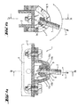
- FIGS. 1 a, 1 b a cut shown in two pivot planes Ia, Ib
- Carrier connection 1 for suspended on a support profile 2 loads L a Rheinan gleichteil 3 with a Schwenkelementfact 4 and an associated, therein in the pivoting plane Ia, by 20 ° and in the pivoting plane Ib by 120 ° pivotally fixable, swivel nut. 5 with an internal thread 6 into which a threaded rod 7 can be screwed.
- the Guide surface of the carrier connection part has a slope area along the Guide slot of 120 ° and greater than 10 ° transverse to the guide slot, which at Industrial halls the usual roof inclines up to 10 ° are directly compensated.
- the Schwenkelementing 4 has, according to FIGS. 2a, 2b, 2c along a first Swivel plane IIb a guide slot 8 with a width B on. Both sides of the Guide slot 8, an edge region 9 is arranged inside the Schwenkelementam 4 a saddle-shaped guide surface 10a with a constant concave canonical curvature having a first radius R1 along the Guide slot 8 and a constant convex canonical curvature with a second radius R2 transverse to the guide slot 8 is formed.
- the guide slot 8 opens into an insertion opening 11 with the triple width B of the guide slot 8.
- Die Insertion opening has a locking element for locking an inserted pivot nut 12 in the form of a resilient pawl.
- the guide surface 10 a is an oppositely shaped guide surface 10 b of Swivel nut 5 according to FIGS. 3a, 3b, 3c suitably assigned.
- the guide surface 10b opposite end side 13 in the form of a hexagonal head of the pivot nut. 5 is the inner thread 6 associated with an inner stop surface 14, to which a bolted threaded rod 7 is jammed.
- the SpoanInstitutteil 3 is in the manner of a screw clamp in rigid U-shaped formed with an arc segment 15 with the Schwenkelementfact 4 and two on both sides along the guide slot 8 adjacent, parallel opposite Clamping legs 16a, 16b with fastening means in the form of threaded holes 17. Der Distance A between the opposite clamping legs 16a, 16b is more than the sum of the flange thickness of the carrier profile 2 (FIG. 5) and the diameter of a interposed tension rod 21 (Fig. 5).
- the carrier connection part 3 has two diametrically offset lying in a plane, from the arc segment 15 with the Schwenkelementfact 4 on both sides transverse to the guide slot adjacent, flat Mounting flanges 18a, 18b with fastening means in the form of along the guide slot 8 oriented slots 19 on.
- an alternative carrier terminal part 3 has two diametrically offset lying in a plane of the arc segment 15 with the guide slot 8 along this adjacent angled mounting flanges 18a, 18b with fastening means in the form of Through holes 23 on.
- each carrier connection part 3 is provided on a double-T-shaped carrier profile 2 arranged.
- two on both sides of the carrier profile 2 arranged and only at one free projecting edge 20 as a line stop fitting are by means Clamping rods 21 mutually positively fixed, with a tilting of the SuanBankmaschine 3 by the flat on the support section 2 and the tie rods 21st adjacent and by means of clamping bolt 22 frictionally clamped clamping leg 16b is prevented.
- the alternative carrier connection part 3 in the manner of a clamp at a free attached side surface of a concrete beam profile 24 by means of anchor 25, wherein between the Concrete support 24 and serving to receive a first threaded rod 7 Carrier connection part 3 'for suspending a second threaded rod 7 a Unterlegewinkel 26 is mounted, the a plastically deformed predetermined bending point 27 in the form of a section with Has recesses.
Landscapes
- Engineering & Computer Science (AREA)
- General Engineering & Computer Science (AREA)
- Mechanical Engineering (AREA)
- Mutual Connection Of Rods And Tubes (AREA)
- Clamps And Clips (AREA)
- Joining Of Building Structures In Genera (AREA)
- Supports For Pipes And Cables (AREA)
- Vehicle Body Suspensions (AREA)
- Fittings On The Vehicle Exterior For Carrying Loads, And Devices For Holding Or Mounting Articles (AREA)
Abstract
Description
- Fig. 1a, 1b
- als Zweiseitenansichten der Trägeranbindung im Teilschnitt
- Fig. 2a, 2b, 2c
- als Dreiseitenansichten des Trägeranschlussteils im Teilschnitt
- Fig. 3a, 3b, 3c
- als Dreiseitenansichten der Schwenkmutter im Teilschnitt
- Fig. 4
- als Dreiseitenansichten einer Variante des Trägeranschlussteils im Teilschnitt
- Fig. 5
- als Anwendungsbeispiel
- Fig. 6
- als alternatives Anwendungsbeispiel
Claims (14)
- Trägeranbindung für abgehängte Lasten (L) mit einem Befestigungsmittel aufweisenden Trägeranschlussteil (3, 3') mit einer Schwenkelementaufnahme (4) und mit einer zugeordneten, darin in zumindest einer Schwenkebene (Ia, Ib) schwenkbar festlegbaren, Schwenkmutter (5) mit einem Innengewinde (6), wobei die Schwenkelementaufnahme (4) längs einer ersten Schwenkebene (Ib) einen Führungsschlitz (8) mit einer, dem Durchmesser einer durchführbaren Gewindestange (7) entsprechenden, Breite (B) aufweist, dadurch gekennzeichnet, dass die Schwenkmutter (5) und ein beidseitig des Führungsschlitzes (8) angeordneter Randbereich (9) jeweils zugeordnete Führungsflächen (10a, 10b) ausbilden, die sattelförmig geformt sind.
- Trägeranbindung nach Anspruch 1, dadurch gekennzeichnet, dass die Führungsfläche (10a, 10b) des Trägeranschlussteils (3, 3') längs des Führungsschlitzes (8) eine konkave und quer zum Führungsschlitz (8) eine konvexe kanonische Krümmung aufweist.
- Trägeranbindung nach Anspruch 1 oder Anspruch 2, dadurch gekennzeichnet, dass die Führungsflächen (10a, 10b) überall jeweils konstante kanonische Krümmungen aufweisen.
- Trägeranbindung nach einem der Ansprüche 1 bis 3, dadurch gekennzeichnet, dass die Führungsfläche (10a, 10b) des Trägeranschlussteils (3, 3') einen Neigungsbereich grösser 90° längs des Führungsschlitzes (8) und grösser 10 ° quer zum Führungsschlitz (8) aufweist.
- Trägeranbindung nach einem der vorherigen Ansprüche, dadurch gekennzeichnet, dass der Führungsschlitz (8) in eine Einführöffnung (11) mit zumindest der doppelten Breite (B) des Führungsschlitzes (8) mündet.
- Trägeranbindung nach einem der vorherigen Ansprüche, dadurch gekennzeichnet, dass die Einführöffnung (11) zur Verriegelung einer eingeführten Schwenkmutter (5) ein Sperrelement (12) aufweist, optional eine federnde Sperrklinke oder eine gegenüber dem Führungsschlitz (8) angeordnete Barriere.
- Trägeranbindung nach einem der vorherigen Ansprüche, dadurch gekennzeichnet, dass dem Innengewinde (6) auf der, der Führungsfläche (10b) gegenüberliegenden, Endseite (13) der Schwenkmutter (5) eine innere Anschlagfläche (14) zugeordnet ist.
- Trägeranbindung nach einem der vorherigen Ansprüche, dadurch gekennzeichnet, dass das Trägeranschlussteil (3, 3') in sich steif U-förmig ausgebildet ist mit einem Bogensegment (15) mit der Schwenkelementaufnahme (4) und zwei beidseitig längs zum Führungsschlitz (8) benachbarten, parallel gegenüberliegenden Spannschenkeln (16a, 16b) mit Befestigungsmitteln.
- Trägeranbindung nach Anspruch 8, dadurch gekennzeichnet, dass der Abstand (A) zwischen den gegenüberliegenden Spannschenkeln (16a, 16b) mehr als das Doppelte der Flanschdicke eines Trägerprofils (2) beträgt.
- Trägeranbindung nach einem der vorherigen Ansprüche, dadurch gekennzeichnet, dass das Trägeranschlussteil (3, 3') zwei diametral versetzt in einer Ebene liegende, vom Bogensegment (15) mit der Schwenkelementaufnahme (4) beidseitig quer zum Führungsschlitz (8) benachbarte Montageflansche (18a, 18b) mit Befestigungsmitteln aufweist.
- Trägeranbindung nach einem der vorherigen Ansprüche, dadurch gekennzeichnet, dass das Trägeranschlussteil (3, 3') sowohl zwei Spannschenkel (16a, 16b) als auch zwei Montageflansche (18a, 18b) aufweist.
- Trägeranbindung nach einem der Ansprüche 1 bis 7, dadurch gekennzeichnet, dass das Trägeranschlussteil (3, 3') zumindest einen, vom Bogensegment (15) mit dem Führungsschlitz (8) benachbart abgewinkelten, flachen Montageflansch (18a, 18b) mit Befestigungsmitteln aufweist.
- Trägeranbindung nach einem der vorherigen Ansprüche, dadurch gekennzeichnet, dass die Befestigungsmittel als längs des Führungsschlitzes (8) orientierte Langlöcher (19) ausgeführt sind.
- Trägeranbindung nach einem der vorherigen Ansprüche, dadurch gekennzeichnet, dass diese ein Bauteil eines in sich aufeinander konstruktiv abgestimmten Montagesystems ist, bestehend aus beliebigen Gruppen von Trägeranbindungen (3, 3'), Trägerprofilen (2), Unterlegewinkeln (26), Schienenrahmenkonstruktionen, Gewindestangen (7), Spannstangen (21), Spannbolzen (22) und/oder Ankern (25).
Applications Claiming Priority (2)
| Application Number | Priority Date | Filing Date | Title |
|---|---|---|---|
| DE102004006204 | 2004-02-09 | ||
| DE102004006204A DE102004006204B3 (de) | 2004-02-09 | 2004-02-09 | Trägeranbindung |
Publications (2)
| Publication Number | Publication Date |
|---|---|
| EP1561983A1 true EP1561983A1 (de) | 2005-08-10 |
| EP1561983B1 EP1561983B1 (de) | 2009-09-23 |
Family
ID=34673209
Family Applications (1)
| Application Number | Title | Priority Date | Filing Date |
|---|---|---|---|
| EP05100654A Expired - Lifetime EP1561983B1 (de) | 2004-02-09 | 2005-02-01 | Schwenkbare Aufhängungsvorrichtung |
Country Status (5)
| Country | Link |
|---|---|
| US (1) | US7543788B2 (de) |
| EP (1) | EP1561983B1 (de) |
| CN (1) | CN100564713C (de) |
| AT (1) | ATE443828T1 (de) |
| DE (2) | DE102004006204B3 (de) |
Cited By (1)
| Publication number | Priority date | Publication date | Assignee | Title |
|---|---|---|---|---|
| CN102071806A (zh) * | 2011-01-06 | 2011-05-25 | 中国建筑第四工程局有限公司 | 一种减小不对称钢悬挂结构变形的方法 |
Families Citing this family (10)
| Publication number | Priority date | Publication date | Assignee | Title |
|---|---|---|---|---|
| KR101273249B1 (ko) * | 2013-01-22 | 2013-06-10 | 김종천 | 조명각 조절이 가능한 엘이디 램프 |
| CN103393287B (zh) * | 2013-08-19 | 2016-03-30 | 天津市傲钢家具有限公司 | 桌架连接机构 |
| US9841047B2 (en) | 2014-06-27 | 2017-12-12 | U.S. Farathane Corporation | Fastener assembly associated with a mounting surface of such as an electronic control module or battery tray, the mounting surface incorporating a flexural and three dimensional configured receiving aperture profile for reliably seating and retaining an associated mounting fastener with low insertion force in comparison to higher extraction force and with minimal loss of material |
| KR101870212B1 (ko) * | 2016-09-09 | 2018-06-22 | 최낙준 | 내진 및 방진용 배관 홀더 |
| CN106994249B (zh) * | 2017-05-23 | 2019-08-16 | 奇业游乐设备(南京)有限公司 | 一种用于空中大冒险游乐设施的天空滑翔装置 |
| FR3086356B1 (fr) * | 2018-09-26 | 2020-09-04 | A Raymond Et Cie | Dispositif d’ecrou encage pour un montage sur un montant creux |
| AU2020289859A1 (en) * | 2019-12-18 | 2021-07-08 | Rhino Rack Australia Pty Limited | Channel Fastener |
| WO2022000016A1 (en) * | 2020-07-02 | 2022-01-06 | Air Diffusion Agencies Pty Ltd | Tension mount improvements |
| US11299095B2 (en) * | 2020-08-11 | 2022-04-12 | Wayne Gary Clarke | Apparatus for securing a side mirror to a vehicle |
| US11613211B2 (en) * | 2020-08-11 | 2023-03-28 | Wayne Gary Clarke | Adapter bracket for securing a side mirror to a vehicle |
Citations (5)
| Publication number | Priority date | Publication date | Assignee | Title |
|---|---|---|---|---|
| US2953874A (en) | 1958-10-27 | 1960-09-27 | Orlan C Kindorf | Concrete insert with swivel support for conduits or the like |
| US4666109A (en) | 1985-01-25 | 1987-05-19 | Draft Systems, Inc. | Tube support assembly |
| EP0452256A1 (de) * | 1990-04-11 | 1991-10-16 | Alusuisse-Lonza Services Ag | Eckverbindung zweier Profile mit C-förmigem Anschluss mittels eines Eckverbinders und Winkelstück zur Herstellung der Verbindung |
| EP0620395A1 (de) * | 1993-04-14 | 1994-10-19 | HILTI Aktiengesellschaft | Tragvorrichtung |
| DE19946222C1 (de) | 1999-09-22 | 2001-04-05 | Roco Rohrbedarf Gmbh | Vorrichtung zur Aufhängung von Rohren an Decken |
Family Cites Families (12)
| Publication number | Priority date | Publication date | Assignee | Title |
|---|---|---|---|---|
| US880415A (en) * | 1907-10-14 | 1908-02-25 | Davis & Furber | Pulley-sustaining hanger. |
| US1491571A (en) * | 1921-01-27 | 1924-04-22 | Edward Ogden J | Concrete insert |
| US1578634A (en) * | 1925-07-31 | 1926-03-30 | Bell Telephone Labor Inc | Clamping and supporting device |
| US2641513A (en) * | 1948-09-30 | 1953-06-09 | Paul A Fryda | Brush handle connection |
| US3081114A (en) * | 1961-10-30 | 1963-03-12 | Howard E Esty | Anchoring device for pipe and the like |
| US3145005A (en) * | 1962-11-20 | 1964-08-18 | Roger H Wester | Detachable pole holder |
| US4565345A (en) * | 1981-11-03 | 1986-01-21 | Peterson Manufacturing Company | Mirror assembly |
| JPS604476A (ja) * | 1983-06-22 | 1985-01-10 | 株式会社加島サドル製作所 | 角度調節型サドル |
| CN2496948Y (zh) * | 2001-07-10 | 2002-06-26 | 高文展 | 钢框架复合外墙板与梁、柱及墙板间的连接结构 |
| CN2600513Y (zh) * | 2003-03-13 | 2004-01-21 | 上海建科建筑设计院 | 悬挂式钢混结构吊杆连接件 |
| US6796760B1 (en) * | 2003-03-21 | 2004-09-28 | Intier Automotive Inc. | Retention structure for a fastener |
| US7189043B2 (en) * | 2005-02-25 | 2007-03-13 | Illinois Tool Works Inc. | Tethered retainer assembly |
-
2004
- 2004-02-09 DE DE102004006204A patent/DE102004006204B3/de not_active Expired - Fee Related
-
2005
- 2005-02-01 EP EP05100654A patent/EP1561983B1/de not_active Expired - Lifetime
- 2005-02-01 AT AT05100654T patent/ATE443828T1/de active
- 2005-02-01 DE DE502005008163T patent/DE502005008163D1/de not_active Expired - Lifetime
- 2005-02-03 CN CNB2005100091389A patent/CN100564713C/zh not_active Expired - Fee Related
- 2005-02-08 US US11/053,404 patent/US7543788B2/en not_active Expired - Fee Related
Patent Citations (5)
| Publication number | Priority date | Publication date | Assignee | Title |
|---|---|---|---|---|
| US2953874A (en) | 1958-10-27 | 1960-09-27 | Orlan C Kindorf | Concrete insert with swivel support for conduits or the like |
| US4666109A (en) | 1985-01-25 | 1987-05-19 | Draft Systems, Inc. | Tube support assembly |
| EP0452256A1 (de) * | 1990-04-11 | 1991-10-16 | Alusuisse-Lonza Services Ag | Eckverbindung zweier Profile mit C-förmigem Anschluss mittels eines Eckverbinders und Winkelstück zur Herstellung der Verbindung |
| EP0620395A1 (de) * | 1993-04-14 | 1994-10-19 | HILTI Aktiengesellschaft | Tragvorrichtung |
| DE19946222C1 (de) | 1999-09-22 | 2001-04-05 | Roco Rohrbedarf Gmbh | Vorrichtung zur Aufhängung von Rohren an Decken |
Cited By (1)
| Publication number | Priority date | Publication date | Assignee | Title |
|---|---|---|---|---|
| CN102071806A (zh) * | 2011-01-06 | 2011-05-25 | 中国建筑第四工程局有限公司 | 一种减小不对称钢悬挂结构变形的方法 |
Also Published As
| Publication number | Publication date |
|---|---|
| CN100564713C (zh) | 2009-12-02 |
| CN1654755A (zh) | 2005-08-17 |
| DE502005008163D1 (de) | 2009-11-05 |
| EP1561983B1 (de) | 2009-09-23 |
| US20050173363A1 (en) | 2005-08-11 |
| US7543788B2 (en) | 2009-06-09 |
| DE102004006204B3 (de) | 2005-09-22 |
| ATE443828T1 (de) | 2009-10-15 |
Similar Documents
| Publication | Publication Date | Title |
|---|---|---|
| DE2003517C3 (de) | Rohrschelle für Rohraufhängungen | |
| US5145132A (en) | Adjustable load bolt adapter bracket assembly | |
| WO1994004860A1 (en) | Connector device | |
| DE102004006204B3 (de) | Trägeranbindung | |
| DE3936198C2 (de) | ||
| AT6961U2 (de) | Verstell- und fixiervorrichtung | |
| EP1561876A1 (de) | Anbindevorrichtung | |
| DE20011063U1 (de) | Montagevorrichtung für Solarkollektoren auf ebenen Flächen | |
| EP0826887B1 (de) | Verbindungseinrichtung | |
| DE2714690A1 (de) | Geruestklemme | |
| DE102004006210B4 (de) | Knotenverbinder | |
| DE202004009557U1 (de) | System zur Aufhängung von Rohren, Leitungen o.dgl. an einer Decke | |
| CH673882A5 (en) | Pipe clamp with holder bar - bar is attached to V=shaped support for pipe with attachment holding pipe down | |
| DE2913703A1 (de) | Raeumliches netzwerk | |
| DE4309041A1 (de) | Säule für Geländer, Zäune oder dergleichen | |
| EP0583701B1 (de) | Schwenkbare Konsole | |
| AT409510B (de) | Wand- und fassaden-system | |
| EP1114935A2 (de) | Knotenverbinder zum Befestigen einer Montageschiene auf Stoss an einer anderen Montageschiene | |
| DE19734556C1 (de) | Anordnung zum Aufhängen einer Rohrleitung | |
| DE10125970A1 (de) | Montageschiene | |
| DE3516680C2 (de) | ||
| EP1561877A2 (de) | Verbindungsvorrichtung | |
| DE19502287C1 (de) | Trägerelement | |
| DE3808544C1 (en) | Suspension device for infusion bottles | |
| EP0638694B1 (de) | Abhängeranker für Doppel T-Träger |
Legal Events
| Date | Code | Title | Description |
|---|---|---|---|
| PUAI | Public reference made under article 153(3) epc to a published international application that has entered the european phase |
Free format text: ORIGINAL CODE: 0009012 |
|
| AK | Designated contracting states |
Kind code of ref document: A1 Designated state(s): AT BE BG CH CY CZ DE DK EE ES FI FR GB GR HU IE IS IT LI LT LU MC NL PL PT RO SE SI SK TR |
|
| AX | Request for extension of the european patent |
Extension state: AL BA HR LV MK YU |
|
| 17P | Request for examination filed |
Effective date: 20060210 |
|
| AKX | Designation fees paid |
Designated state(s): AT BE BG CH CY CZ DE DK EE ES FI FR GB GR HU IE IS IT LI LT LU MC NL PL PT RO SE SI SK TR |
|
| 17Q | First examination report despatched |
Effective date: 20090220 |
|
| GRAP | Despatch of communication of intention to grant a patent |
Free format text: ORIGINAL CODE: EPIDOSNIGR1 |
|
| GRAS | Grant fee paid |
Free format text: ORIGINAL CODE: EPIDOSNIGR3 |
|
| GRAA | (expected) grant |
Free format text: ORIGINAL CODE: 0009210 |
|
| AK | Designated contracting states |
Kind code of ref document: B1 Designated state(s): AT BE BG CH CY CZ DE DK EE ES FI FR GB GR HU IE IS IT LI LT LU MC NL PL PT RO SE SI SK TR |
|
| REG | Reference to a national code |
Ref country code: GB Ref legal event code: FG4D Free format text: NOT ENGLISH |
|
| REG | Reference to a national code |
Ref country code: CH Ref legal event code: EP |
|
| REG | Reference to a national code |
Ref country code: IE Ref legal event code: FG4D |
|
| REF | Corresponds to: |
Ref document number: 502005008163 Country of ref document: DE Date of ref document: 20091105 Kind code of ref document: P |
|
| PG25 | Lapsed in a contracting state [announced via postgrant information from national office to epo] |
Ref country code: SE Free format text: LAPSE BECAUSE OF FAILURE TO SUBMIT A TRANSLATION OF THE DESCRIPTION OR TO PAY THE FEE WITHIN THE PRESCRIBED TIME-LIMIT Effective date: 20090923 Ref country code: FI Free format text: LAPSE BECAUSE OF FAILURE TO SUBMIT A TRANSLATION OF THE DESCRIPTION OR TO PAY THE FEE WITHIN THE PRESCRIBED TIME-LIMIT Effective date: 20090923 Ref country code: LT Free format text: LAPSE BECAUSE OF FAILURE TO SUBMIT A TRANSLATION OF THE DESCRIPTION OR TO PAY THE FEE WITHIN THE PRESCRIBED TIME-LIMIT Effective date: 20090923 |
|
| LTIE | Lt: invalidation of european patent or patent extension |
Effective date: 20090923 |
|
| PG25 | Lapsed in a contracting state [announced via postgrant information from national office to epo] |
Ref country code: SI Free format text: LAPSE BECAUSE OF FAILURE TO SUBMIT A TRANSLATION OF THE DESCRIPTION OR TO PAY THE FEE WITHIN THE PRESCRIBED TIME-LIMIT Effective date: 20090923 Ref country code: PL Free format text: LAPSE BECAUSE OF FAILURE TO SUBMIT A TRANSLATION OF THE DESCRIPTION OR TO PAY THE FEE WITHIN THE PRESCRIBED TIME-LIMIT Effective date: 20090923 |
|
| NLV1 | Nl: lapsed or annulled due to failure to fulfill the requirements of art. 29p and 29m of the patents act | ||
| PG25 | Lapsed in a contracting state [announced via postgrant information from national office to epo] |
Ref country code: CY Free format text: LAPSE BECAUSE OF FAILURE TO SUBMIT A TRANSLATION OF THE DESCRIPTION OR TO PAY THE FEE WITHIN THE PRESCRIBED TIME-LIMIT Effective date: 20090923 |
|
| REG | Reference to a national code |
Ref country code: IE Ref legal event code: FD4D |
|
| PG25 | Lapsed in a contracting state [announced via postgrant information from national office to epo] |
Ref country code: CZ Free format text: LAPSE BECAUSE OF FAILURE TO SUBMIT A TRANSLATION OF THE DESCRIPTION OR TO PAY THE FEE WITHIN THE PRESCRIBED TIME-LIMIT Effective date: 20090923 Ref country code: IE Free format text: LAPSE BECAUSE OF FAILURE TO SUBMIT A TRANSLATION OF THE DESCRIPTION OR TO PAY THE FEE WITHIN THE PRESCRIBED TIME-LIMIT Effective date: 20090923 Ref country code: EE Free format text: LAPSE BECAUSE OF FAILURE TO SUBMIT A TRANSLATION OF THE DESCRIPTION OR TO PAY THE FEE WITHIN THE PRESCRIBED TIME-LIMIT Effective date: 20090923 Ref country code: ES Free format text: LAPSE BECAUSE OF FAILURE TO SUBMIT A TRANSLATION OF THE DESCRIPTION OR TO PAY THE FEE WITHIN THE PRESCRIBED TIME-LIMIT Effective date: 20100103 Ref country code: IS Free format text: LAPSE BECAUSE OF FAILURE TO SUBMIT A TRANSLATION OF THE DESCRIPTION OR TO PAY THE FEE WITHIN THE PRESCRIBED TIME-LIMIT Effective date: 20100123 Ref country code: PT Free format text: LAPSE BECAUSE OF FAILURE TO SUBMIT A TRANSLATION OF THE DESCRIPTION OR TO PAY THE FEE WITHIN THE PRESCRIBED TIME-LIMIT Effective date: 20100125 Ref country code: RO Free format text: LAPSE BECAUSE OF FAILURE TO SUBMIT A TRANSLATION OF THE DESCRIPTION OR TO PAY THE FEE WITHIN THE PRESCRIBED TIME-LIMIT Effective date: 20090923 |
|
| PG25 | Lapsed in a contracting state [announced via postgrant information from national office to epo] |
Ref country code: SK Free format text: LAPSE BECAUSE OF FAILURE TO SUBMIT A TRANSLATION OF THE DESCRIPTION OR TO PAY THE FEE WITHIN THE PRESCRIBED TIME-LIMIT Effective date: 20090923 |
|
| PG25 | Lapsed in a contracting state [announced via postgrant information from national office to epo] |
Ref country code: NL Free format text: LAPSE BECAUSE OF FAILURE TO SUBMIT A TRANSLATION OF THE DESCRIPTION OR TO PAY THE FEE WITHIN THE PRESCRIBED TIME-LIMIT Effective date: 20090923 Ref country code: DK Free format text: LAPSE BECAUSE OF FAILURE TO SUBMIT A TRANSLATION OF THE DESCRIPTION OR TO PAY THE FEE WITHIN THE PRESCRIBED TIME-LIMIT Effective date: 20090923 |
|
| PLBE | No opposition filed within time limit |
Free format text: ORIGINAL CODE: 0009261 |
|
| STAA | Information on the status of an ep patent application or granted ep patent |
Free format text: STATUS: NO OPPOSITION FILED WITHIN TIME LIMIT |
|
| BERE | Be: lapsed |
Owner name: HILTI AKTIENGESELLSCHAFT Effective date: 20100228 |
|
| 26N | No opposition filed |
Effective date: 20100624 |
|
| PG25 | Lapsed in a contracting state [announced via postgrant information from national office to epo] |
Ref country code: MC Free format text: LAPSE BECAUSE OF NON-PAYMENT OF DUE FEES Effective date: 20100301 Ref country code: GR Free format text: LAPSE BECAUSE OF FAILURE TO SUBMIT A TRANSLATION OF THE DESCRIPTION OR TO PAY THE FEE WITHIN THE PRESCRIBED TIME-LIMIT Effective date: 20091224 |
|
| PG25 | Lapsed in a contracting state [announced via postgrant information from national office to epo] |
Ref country code: BE Free format text: LAPSE BECAUSE OF NON-PAYMENT OF DUE FEES Effective date: 20100228 |
|
| PG25 | Lapsed in a contracting state [announced via postgrant information from national office to epo] |
Ref country code: IT Free format text: LAPSE BECAUSE OF FAILURE TO SUBMIT A TRANSLATION OF THE DESCRIPTION OR TO PAY THE FEE WITHIN THE PRESCRIBED TIME-LIMIT Effective date: 20090923 |
|
| PG25 | Lapsed in a contracting state [announced via postgrant information from national office to epo] |
Ref country code: LU Free format text: LAPSE BECAUSE OF NON-PAYMENT OF DUE FEES Effective date: 20100201 Ref country code: BG Free format text: LAPSE BECAUSE OF FAILURE TO SUBMIT A TRANSLATION OF THE DESCRIPTION OR TO PAY THE FEE WITHIN THE PRESCRIBED TIME-LIMIT Effective date: 20090923 Ref country code: HU Free format text: LAPSE BECAUSE OF FAILURE TO SUBMIT A TRANSLATION OF THE DESCRIPTION OR TO PAY THE FEE WITHIN THE PRESCRIBED TIME-LIMIT Effective date: 20100324 |
|
| PG25 | Lapsed in a contracting state [announced via postgrant information from national office to epo] |
Ref country code: TR Free format text: LAPSE BECAUSE OF FAILURE TO SUBMIT A TRANSLATION OF THE DESCRIPTION OR TO PAY THE FEE WITHIN THE PRESCRIBED TIME-LIMIT Effective date: 20090923 |
|
| PGFP | Annual fee paid to national office [announced via postgrant information from national office to epo] |
Ref country code: CH Payment date: 20140212 Year of fee payment: 10 |
|
| PGFP | Annual fee paid to national office [announced via postgrant information from national office to epo] |
Ref country code: FR Payment date: 20140211 Year of fee payment: 10 Ref country code: AT Payment date: 20140128 Year of fee payment: 10 |
|
| PGFP | Annual fee paid to national office [announced via postgrant information from national office to epo] |
Ref country code: GB Payment date: 20140129 Year of fee payment: 10 |
|
| REG | Reference to a national code |
Ref country code: CH Ref legal event code: PL |
|
| REG | Reference to a national code |
Ref country code: AT Ref legal event code: MM01 Ref document number: 443828 Country of ref document: AT Kind code of ref document: T Effective date: 20150201 |
|
| GBPC | Gb: european patent ceased through non-payment of renewal fee |
Effective date: 20150201 |
|
| PG25 | Lapsed in a contracting state [announced via postgrant information from national office to epo] |
Ref country code: LI Free format text: LAPSE BECAUSE OF NON-PAYMENT OF DUE FEES Effective date: 20150228 Ref country code: CH Free format text: LAPSE BECAUSE OF NON-PAYMENT OF DUE FEES Effective date: 20150228 |
|
| REG | Reference to a national code |
Ref country code: FR Ref legal event code: ST Effective date: 20151030 |
|
| PG25 | Lapsed in a contracting state [announced via postgrant information from national office to epo] |
Ref country code: AT Free format text: LAPSE BECAUSE OF NON-PAYMENT OF DUE FEES Effective date: 20150201 |
|
| PG25 | Lapsed in a contracting state [announced via postgrant information from national office to epo] |
Ref country code: GB Free format text: LAPSE BECAUSE OF NON-PAYMENT OF DUE FEES Effective date: 20150201 |
|
| PG25 | Lapsed in a contracting state [announced via postgrant information from national office to epo] |
Ref country code: FR Free format text: LAPSE BECAUSE OF NON-PAYMENT OF DUE FEES Effective date: 20150302 |
|
| PGFP | Annual fee paid to national office [announced via postgrant information from national office to epo] |
Ref country code: DE Payment date: 20190219 Year of fee payment: 15 |
|
| REG | Reference to a national code |
Ref country code: DE Ref legal event code: R119 Ref document number: 502005008163 Country of ref document: DE |
|
| PG25 | Lapsed in a contracting state [announced via postgrant information from national office to epo] |
Ref country code: DE Free format text: LAPSE BECAUSE OF NON-PAYMENT OF DUE FEES Effective date: 20200901 |