EP1561935A1 - Dieselmaschine, insbesondere Grossdieselmotor, mit einem elektronischen Steuerungssystem - Google Patents
Dieselmaschine, insbesondere Grossdieselmotor, mit einem elektronischen Steuerungssystem Download PDFInfo
- Publication number
- EP1561935A1 EP1561935A1 EP05405003A EP05405003A EP1561935A1 EP 1561935 A1 EP1561935 A1 EP 1561935A1 EP 05405003 A EP05405003 A EP 05405003A EP 05405003 A EP05405003 A EP 05405003A EP 1561935 A1 EP1561935 A1 EP 1561935A1
- Authority
- EP
- European Patent Office
- Prior art keywords
- modules
- control
- global
- functional
- module
- Prior art date
- Legal status (The legal status is an assumption and is not a legal conclusion. Google has not performed a legal analysis and makes no representation as to the accuracy of the status listed.)
- Granted
Links
Images

Classifications
-
- B—PERFORMING OPERATIONS; TRANSPORTING
- B23—MACHINE TOOLS; METAL-WORKING NOT OTHERWISE PROVIDED FOR
- B23C—MILLING
- B23C5/00—Milling-cutters
- B23C5/006—Details of the milling cutter body
-
- F—MECHANICAL ENGINEERING; LIGHTING; HEATING; WEAPONS; BLASTING
- F02—COMBUSTION ENGINES; HOT-GAS OR COMBUSTION-PRODUCT ENGINE PLANTS
- F02D—CONTROLLING COMBUSTION ENGINES
- F02D41/00—Electrical control of supply of combustible mixture or its constituents
- F02D41/008—Controlling each cylinder individually
-
- B—PERFORMING OPERATIONS; TRANSPORTING
- B23—MACHINE TOOLS; METAL-WORKING NOT OTHERWISE PROVIDED FOR
- B23C—MILLING
- B23C5/00—Milling-cutters
- B23C5/16—Milling-cutters characterised by physical features other than shape
- B23C5/20—Milling-cutters characterised by physical features other than shape with removable cutter bits or teeth or cutting inserts
- B23C5/22—Securing arrangements for bits or teeth or cutting inserts
-
- B—PERFORMING OPERATIONS; TRANSPORTING
- B23—MACHINE TOOLS; METAL-WORKING NOT OTHERWISE PROVIDED FOR
- B23C—MILLING
- B23C5/00—Milling-cutters
- B23C5/16—Milling-cutters characterised by physical features other than shape
- B23C5/20—Milling-cutters characterised by physical features other than shape with removable cutter bits or teeth or cutting inserts
- B23C5/22—Securing arrangements for bits or teeth or cutting inserts
- B23C5/24—Securing arrangements for bits or teeth or cutting inserts adjustable
- B23C5/2472—Securing arrangements for bits or teeth or cutting inserts adjustable the adjusting means being screws
-
- F—MECHANICAL ENGINEERING; LIGHTING; HEATING; WEAPONS; BLASTING
- F02—COMBUSTION ENGINES; HOT-GAS OR COMBUSTION-PRODUCT ENGINE PLANTS
- F02D—CONTROLLING COMBUSTION ENGINES
- F02D41/00—Electrical control of supply of combustible mixture or its constituents
- F02D41/22—Safety or indicating devices for abnormal conditions
-
- F—MECHANICAL ENGINEERING; LIGHTING; HEATING; WEAPONS; BLASTING
- F02—COMBUSTION ENGINES; HOT-GAS OR COMBUSTION-PRODUCT ENGINE PLANTS
- F02D—CONTROLLING COMBUSTION ENGINES
- F02D41/00—Electrical control of supply of combustible mixture or its constituents
- F02D41/24—Electrical control of supply of combustible mixture or its constituents characterised by the use of digital means
- F02D41/26—Electrical control of supply of combustible mixture or its constituents characterised by the use of digital means using computer, e.g. microprocessor
- F02D41/266—Electrical control of supply of combustible mixture or its constituents characterised by the use of digital means using computer, e.g. microprocessor the computer being backed-up or assisted by another circuit, e.g. analogue
-
- F—MECHANICAL ENGINEERING; LIGHTING; HEATING; WEAPONS; BLASTING
- F02—COMBUSTION ENGINES; HOT-GAS OR COMBUSTION-PRODUCT ENGINE PLANTS
- F02D—CONTROLLING COMBUSTION ENGINES
- F02D41/00—Electrical control of supply of combustible mixture or its constituents
- F02D41/30—Controlling fuel injection
- F02D41/38—Controlling fuel injection of the high pressure type
-
- B23C2200/286—
-
- B—PERFORMING OPERATIONS; TRANSPORTING
- B23—MACHINE TOOLS; METAL-WORKING NOT OTHERWISE PROVIDED FOR
- B23C—MILLING
- B23C2210/00—Details of milling cutters
- B23C2210/16—Fixation of inserts or cutting bits in the tool
- B23C2210/165—Fixation bolts
-
- B—PERFORMING OPERATIONS; TRANSPORTING
- B23—MACHINE TOOLS; METAL-WORKING NOT OTHERWISE PROVIDED FOR
- B23C—MILLING
- B23C2210/00—Details of milling cutters
- B23C2210/20—Number of cutting edges
- B23C2210/205—Number of cutting edges six
-
- B—PERFORMING OPERATIONS; TRANSPORTING
- B23—MACHINE TOOLS; METAL-WORKING NOT OTHERWISE PROVIDED FOR
- B23C—MILLING
- B23C2270/00—Details of milling machines, milling processes or milling tools not otherwise provided for
- B23C2270/20—Milling external areas of components
Definitions
- the invention relates to a diesel engine, in particular a Large diesel engine, with an electronic control system according to The preamble of claim 1 and a use of the diesel engine.
- a diesel engine in particular a Large diesel engine
- an electronic control system according to The preamble of claim 1 and a use of the diesel engine.
- the Large diesel engine can be both a two-stroke and a four-stroke diesel engine be.
- the object of the invention is to provide a large diesel engine, the one electronically controlled diesel engine is where the control system for the overall engine and the individual cylinders using a minimal number of electronic system components out of these is composable. A minimum number is reduced for reasons Cost and increased reliability advantageous. This task is done by the solved defined in claim 1 machine.
- the diesel engine which is in particular a large diesel engine, has a electronic control system.
- This machine is a multiple Cylinder comprehensive engine, in which by the control system local, the Cylinder related functions and global, the entire engine relevant functions can be influenced.
- Each cylinder is a module assigned to the control system.
- Each of these control modules includes an identically formed logic circuit having a first and a second functional section. With the first functional section is the assigned cylinder controllable.
- the global functions are through one the modules distributed control influenced, namely such that for at least a portion of the modules, each with the second Functional subarea in interaction with second functional subareas of the other modules the global motor control in a redundant way is feasible. Due to the redundancy remains in case of error at least one Part of the engine power maintained.
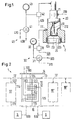
- the pumps 31, 41 and organs 32, 42 are via signal transmitting Connections 310, 410, 320 and 420, respectively, to the control system 1 connected.
- a connecting line 100 drawn which is representative of the above Compounds 310, 410, 320 and 420 and many others not mentioned Compounds is indicated.
- Each cylinder 2 is a module 10 or one of the dash-dotted lines indicated modules 10 ', 10 ", 10' '' of the Control system 1 assigned.
- Each of these control modules 10, 10 ', 10 ", 10 '' ' comprises an identically formed logic circuit with a first Function section 11 and a second functional section 12. With the first functional portion 11 of the associated cylinder 2 is controllable.
- the second functional sections 12 are in terms of global functions set up. The two functional sections 11 and 12 form with advantage together a single logic circuit, not in modular subunits is separable.
- All modules 10 are equipped with an identical operating program.
- the integration of the modules 10 in the control system 1 is through Connecting cables made with plugs, the functionalities of the individual modules 10 resulting from these compounds.
- By the Inserting the plug at the intended connection points is the functionality of the individual module 10 through the operating program detected and activated.
- the second Functional portion 12 of the module 10 with the corresponding second Functional portion 12 (not shown) of another module 10 'paired; and with this pair a global engine control is operated.
- Two other modules, such as modules 10 "and 10" ', are also included such pair of second functional portions 12 are provided.
- the global motor control can thus be implemented in a redundant manner perform simultaneous operation of the two pairs.
- All control modules 10, 10 ', 10 ", 10' '' are the same connections to Signal inputs and outputs are at least in part on the redundant bus line systems 13, 14 made (dash-dotted line 13 'is continuation of the line 13).
- the redundant bus line systems 13, 14 made (dash-dotted line 13 'is continuation of the line 13).
- the two pairs of second functional sections 12 are advantageous coupled to their outputs.
- components of the logic circuit they are protected against each other, so that in case of failure of one of the modules, for example, module 10 ', a continuation of the global Motor control - undamaged by the failing module 10 '- is guaranteed.
- connection connections 123, 124 or Connections to discrete outputs are not needed, lack of economic Reasons appropriate connection connections 123, 124 or Connections to discrete outputs.
- the individual modules 10 are advantageous in the control system 1 such arranged and connected that to replace a defective module 10 'only perform local disassembly operations on this module 10' are. In the absence of a single module, the control system remains continue to work.
- control systems 1 of the inventive machine are intended in particular for use on a deep-sea vessel, on which the machine turns a marine propeller shaft.
- the control modules 10 have signal inputs for this use, through which they provide information, inter alia, with a ship alarm system, a Safety system and electronic speed control of Can replace marine propeller shaft, so that with this information Control system 1 is additionally influenced.
- the ship alarm system, the safety system and the speed control, which are given as examples are in Fig. 2 is a symbolic representation by blocks 5 and 6, the through connections 500 and 600, respectively, to the third bus system 15 are connected.
- Fig. 3 shows a second control system 1 to an inventive Diesel engine.
- This control system 1 comprises - as far as it is shown - the following components: modules 10a, 10b, 10c, 10d, 10e connected to the two Bus line systems 13 and 14 are connected; a block 7, which is up relates a first part of the global functions (e.g. Safety system, speed control); and actuators 8a, 8b, 8c and 9a, 9b ("actuators"), referring to another part of the global functions Respectively.
- Block 7 is controlled redundantly: over two Bus line systems 17a, 17b (instead of the bus line system 15) and through a simultaneous operation of two modules 10a and 10b. In case of failure of one of the modules 10a or 10b, the block 7 continues to receive the control needed information.
- the actuators 8a, 8b, 8c and 9a, 9b are redundant generating Number available. They are connected via bus lines 18a, 18b and 18c to the Modules 10c, 10d and 10e connected. In case of failure of an actuator is with the appropriate modules an adjustment in the operation of the intact Actuators causes.
- the actuators 8a, 8b and 8c are, for example, three Pumps for a servo oil and the actuators 9a and 9b pumps for the Fuel 300, which is to be fed into the accumulator 33. In case of failure
- the actuator 8a with the corresponding modules 10d and 10e of the control system 1 an adjustment in the operation of the intact Actuators 8b and 8c causes.
Landscapes
- Engineering & Computer Science (AREA)
- Mechanical Engineering (AREA)
- General Engineering & Computer Science (AREA)
- Chemical & Material Sciences (AREA)
- Combustion & Propulsion (AREA)
- Computer Hardware Design (AREA)
- Microelectronics & Electronic Packaging (AREA)
- Electrical Control Of Air Or Fuel Supplied To Internal-Combustion Engine (AREA)
- Combined Controls Of Internal Combustion Engines (AREA)
- Output Control And Ontrol Of Special Type Engine (AREA)
Abstract
Description
- Fig. 1
- einen zentralen Ausschnitt eines Grossdieselmotors, im Speziellen eines Zweitakt-Dieselmotors,
- Fig. 2
- ein stark vereinfachtes Schema eines Steuerungssystems, mit dem der Dieselmotor der Fig. 1 gemäss der Erfindung steuerbar ist, und
- Fig. 3
- ein zweites Steuerungssystem zu einem erfindungsgemässen Dieselmotor.
Claims (10)
- Dieselmaschine, insbesondere Grossdieselmotor, mit einem elektronischen Steuerungssystem (1), welche Maschine ein mehrere Zylinder (2) umfassender Motor ist, bei dem durch das Steuerungssystem lokale, die Zylinder betreffende Funktionen und globale, den gesamten Motor betreffende Funktionen beeinflussbar sind,
dadurch gekennzeichnet, dass jeder Zylinder einem Modul (10, 10', 10", 10'''; 10a, 10b, ...) des Steuerungssystems zugeordnet ist, dass jeder dieser Steuerungsmodule (10) eine identisch ausgebildete Logikschaltung mit einem ersten und einem zweiten Funktionsteilbereich (11, 12) umfasst, dass mit dem ersten Funktionsteilbereich (11) der zugeordnete Zylinder steuerbar ist und dass die globalen Funktionen durch eine auf die Module verteilte Steuerung beeinflussbar sind, nämlich so, dass für mindestens einen Teil der Module mit jeweils dem zweiten Funktionsteilbereich in Zusammenspiel mit zweiten Funktionsteilbereichen der weiteren Module die globale Motorsteuerung in einer redundanten Weise durchführbar ist, wobei in einem Fehlerfall aufgrund der Redundanz zumindest ein Teil der Motorleistung aufrecht erhalten bleibt. - Maschine nach Anspruch 1, dadurch gekennzeichnet, dass die lokalen und globalen Funktionen durch ein simultanes Betreiben der Module (10, 10', 10", 10'''; 10a, 10b, ...) mit identischem Betriebsprogramm durchführbar sind.
- Maschine nach Anspruch 1 oder 2, dadurch gekennzeichnet, dass für mindestens einen Teil der globalen Funktionen eine Mehrzahl von gleichen Aktoren (8a, 8b, 8c; 9a, 9b) einsetzbar sind, dass diese Aktoren in einer Redundanz erzeugenden Anzahl vorhanden sind und dass jedem dieser Aktoren jeweils nur ein Modul (10c, 10d, 10e) zugeordnet ist, wobei bei Ausfall eines Aktors mit den entsprechenden Modulen eine Anpassung beim Betrieb der intakten Aktoren bewirkbar ist.
- Maschine nach Anspruch 1, dadurch gekennzeichnet, dass der zweite Funktionsteilbereich (12) der Logikschaltung eines ersten Moduls (10) gepaart mit dem entsprechenden zweiten Funktionsteilbereich eines weiteren Moduls (10') für die globale Motorsteuerung vorgesehen ist, dass zwei weitere Module (10", 10"') mit einem derartigen Paar von zweiten Funktionsteilbereichen vorgesehen sind und dass die globale Motorsteuerung in redundanter Weise durch ein simultanes Betreiben der beiden Paare (10, 10' und 10", 10''') durchführbar ist.
- Maschine nach Anspruch 4, dadurch gekennzeichnet, dass die beiden Paare (10, 10' und 10", 10"') von zweiten Funktionsteilbereichen (12) an ihren Ausgängen gekoppelt und mittels Komponenten der Logikschaltung gegeneinander geschützt sind, so dass bei einem Versagen eines der Module (10') eine Weiterführung der globalen Motorsteuerung - unbeeinträchtigt durch den versagenden Modul (10') - gewährleistet ist.
- Maschine nach einem der Ansprüche 1 bis 5, dadurch gekennzeichnet, dass alle Steuerungsmodule (10, 10', 10", 10"') gleich sind, dass Verbindungen zu Signaleingängen sowie -ausgängen zumindest zu einem Teil über redundante Busleitungsysteme (13, 14) hergestellt sind und dass zur Integrierung der Module im Steuerungssystem (1) weitere elektronische Schaltungen nicht erforderlich sind.
- Maschine nach einem der Ansprüche 1 bis 6, dadurch gekennzeichnet, dass bei Modulen (10), deren zweiter Funktionsteilbereich (12) der Logikschaltung zur globalen Motorsteuerung nicht benötigt wird, entsprechende Anschlussverbindungen (123, 124) oder Verbindungen zu diskreten Ausgängen fehlen.
- Maschine nach einem der Ansprüche 1 bis 7, dadurch gekennzeichnet, dass die einzelnen Module (10) im Steuerungssystem (1) derart angeordnet und angeschlossen sind, dass zum Ersetzen eines defekten Moduls (10') lediglich lokale Demontageeingriffe an diesem Modul durchzuführen sind, und dass beim Fehlen eines einzelnen Moduls das Steuerungssystem weiter arbeitsfähig bleibt.
- Maschine nach einem der Ansprüche 1 bis 8, dadurch gekennzeichnet, dass die Module (10) des Steuerungssystems (1) jeweils mit folgenden Komponenten des Motors in signalübermittelnder Verbindung (100) stehen:einem Einspritzsystem (30) für den zugeordneten Zylinder (2) zum Einspeisen von flüssigem Brennstoff (300),einem Gaswechselsystem (20) für den zugeordneten Zylinder,Pumpen (31, 41) zum Zuführen des Brennstoffs und eines Steuermediums (400),einem Akkumulator (43) für das Steuermedium und einem Akkumulator (33) für den Brennstoff, einem sogenannten "Common Rail", wobei diese Akkumulatoren mit den Pumpen, den Einspritzsystemen und den Gaswechselsystemen verbunden sind,einem hydraulischen System mit Organen zur Durchführung des Einspritzens und des Gaswechsels,Winkelerfassung zur Synchronisation der lokalen und globalen Funktionen mit der Drehung der vom Motor angetriebenen Welle, undVorrichtungen zum Regeln der Brennstoffzufuhr sowie des Gaswechsels und zur Steuerung einer Startluftzufuhr.
- Verwendung einer Maschine gemäss einem der Ansprüche 1 bis 8 auf einem Hochseeschiff zum Drehen einer Schiffsantriebswelle, wobei die Steuerungsmodule (10) Signaleingänge aufweisen, durch die sie Information unter anderem von einem Schiffsalarmsystem (5), von einem Sicherheitssystem und von einer elektronischen Drehzahlregelung (6) der Schiffsantriebswelle zur Beeinflussung des Steuerungssystems (1) empfangen können.
Priority Applications (1)
| Application Number | Priority Date | Filing Date | Title |
|---|---|---|---|
| EP05405003A EP1561935B1 (de) | 2004-02-05 | 2005-01-06 | Dieselmaschine, insbesondere Grossdieselmotor, mit einem elektronischen Steuerungssystem |
Applications Claiming Priority (3)
| Application Number | Priority Date | Filing Date | Title |
|---|---|---|---|
| EP04405073 | 2004-02-05 | ||
| EP04405073 | 2004-02-05 | ||
| EP05405003A EP1561935B1 (de) | 2004-02-05 | 2005-01-06 | Dieselmaschine, insbesondere Grossdieselmotor, mit einem elektronischen Steuerungssystem |
Publications (2)
| Publication Number | Publication Date |
|---|---|
| EP1561935A1 true EP1561935A1 (de) | 2005-08-10 |
| EP1561935B1 EP1561935B1 (de) | 2010-05-05 |
Family
ID=34878357
Family Applications (1)
| Application Number | Title | Priority Date | Filing Date |
|---|---|---|---|
| EP05405003A Expired - Lifetime EP1561935B1 (de) | 2004-02-05 | 2005-01-06 | Dieselmaschine, insbesondere Grossdieselmotor, mit einem elektronischen Steuerungssystem |
Country Status (7)
| Country | Link |
|---|---|
| EP (1) | EP1561935B1 (de) |
| JP (1) | JP4381992B2 (de) |
| KR (1) | KR101144759B1 (de) |
| CN (1) | CN100404832C (de) |
| AT (1) | ATE467043T1 (de) |
| DE (1) | DE502005009505D1 (de) |
| DK (1) | DK1561935T3 (de) |
Cited By (3)
| Publication number | Priority date | Publication date | Assignee | Title |
|---|---|---|---|---|
| WO2010130872A1 (en) * | 2009-05-13 | 2010-11-18 | Wärtsilä Finland Oy | Engine fuel supply control |
| WO2011015198A1 (de) * | 2009-08-05 | 2011-02-10 | Man Diesel & Turbo Se | Mehrmotorenanlage und verfahren zum betreiben dieser |
| WO2018158491A1 (en) * | 2017-03-02 | 2018-09-07 | Wärtsilä Finland Oy | Electrical system for piston engine and method for operating electrical device |
Families Citing this family (2)
| Publication number | Priority date | Publication date | Assignee | Title |
|---|---|---|---|---|
| JP4629702B2 (ja) * | 2007-06-14 | 2011-02-09 | マン・ディーゼル・アンド・ターボ,フィリアル・アフ・マン・ディーゼル・アンド・ターボ・エスイー,ティスクランド | 分散制御システム |
| DE102008054589B3 (de) * | 2008-12-12 | 2010-08-19 | Thielert Aircraft Engines Gmbh | Motorsteuerungssystem für einen Flugdieselmotor |
Citations (5)
| Publication number | Priority date | Publication date | Assignee | Title |
|---|---|---|---|---|
| DE19745765A1 (de) * | 1996-10-28 | 1998-04-30 | Man B & W Diesel Gmbh | Mehrzylindriger Verbrennungsmotor mit einem elektronischen Steuersystem |
| WO1998028530A1 (en) * | 1996-12-20 | 1998-07-02 | Lucas Industries Plc | Control system |
| US5775296A (en) * | 1994-09-11 | 1998-07-07 | Mecel Ab | Arrangement and method for configuration of distributed computer networks implemented in multi cylinder combustion engines |
| EP0989297A1 (de) | 1998-09-21 | 2000-03-29 | Wärtsilä NSD Schweiz AG | Hubkolbenbrennkraftmaschine |
| JP2003201909A (ja) * | 2002-01-09 | 2003-07-18 | Mitsubishi Heavy Ind Ltd | ディーゼル機関制御装置、ディーゼル機関及び船舶 |
Family Cites Families (2)
| Publication number | Priority date | Publication date | Assignee | Title |
|---|---|---|---|---|
| JPS5811383U (ja) * | 1981-07-14 | 1983-01-25 | 三菱電機株式会社 | 伝送装置 |
| JP4112339B2 (ja) * | 2002-11-15 | 2008-07-02 | 三菱重工業株式会社 | 船用機関制御装置 |
-
2005
- 2005-01-06 DE DE502005009505T patent/DE502005009505D1/de not_active Expired - Lifetime
- 2005-01-06 AT AT05405003T patent/ATE467043T1/de not_active IP Right Cessation
- 2005-01-06 DK DK05405003.4T patent/DK1561935T3/da active
- 2005-01-06 EP EP05405003A patent/EP1561935B1/de not_active Expired - Lifetime
- 2005-01-13 KR KR1020050003252A patent/KR101144759B1/ko not_active Expired - Fee Related
- 2005-01-14 JP JP2005007253A patent/JP4381992B2/ja not_active Expired - Fee Related
- 2005-02-04 CN CNB2005100083310A patent/CN100404832C/zh not_active Expired - Fee Related
Patent Citations (5)
| Publication number | Priority date | Publication date | Assignee | Title |
|---|---|---|---|---|
| US5775296A (en) * | 1994-09-11 | 1998-07-07 | Mecel Ab | Arrangement and method for configuration of distributed computer networks implemented in multi cylinder combustion engines |
| DE19745765A1 (de) * | 1996-10-28 | 1998-04-30 | Man B & W Diesel Gmbh | Mehrzylindriger Verbrennungsmotor mit einem elektronischen Steuersystem |
| WO1998028530A1 (en) * | 1996-12-20 | 1998-07-02 | Lucas Industries Plc | Control system |
| EP0989297A1 (de) | 1998-09-21 | 2000-03-29 | Wärtsilä NSD Schweiz AG | Hubkolbenbrennkraftmaschine |
| JP2003201909A (ja) * | 2002-01-09 | 2003-07-18 | Mitsubishi Heavy Ind Ltd | ディーゼル機関制御装置、ディーゼル機関及び船舶 |
Non-Patent Citations (1)
| Title |
|---|
| PATENT ABSTRACTS OF JAPAN vol. 2003, no. 11 5 November 2003 (2003-11-05) * |
Cited By (5)
| Publication number | Priority date | Publication date | Assignee | Title |
|---|---|---|---|---|
| WO2010130872A1 (en) * | 2009-05-13 | 2010-11-18 | Wärtsilä Finland Oy | Engine fuel supply control |
| WO2011015198A1 (de) * | 2009-08-05 | 2011-02-10 | Man Diesel & Turbo Se | Mehrmotorenanlage und verfahren zum betreiben dieser |
| CN102472190A (zh) * | 2009-08-05 | 2012-05-23 | 曼柴油机和涡轮机欧洲股份公司 | 多发动机设备及其工作方法 |
| CN102472190B (zh) * | 2009-08-05 | 2015-08-19 | 曼柴油机和涡轮机欧洲股份公司 | 多发动机设备及其工作方法 |
| WO2018158491A1 (en) * | 2017-03-02 | 2018-09-07 | Wärtsilä Finland Oy | Electrical system for piston engine and method for operating electrical device |
Also Published As
| Publication number | Publication date |
|---|---|
| EP1561935B1 (de) | 2010-05-05 |
| CN100404832C (zh) | 2008-07-23 |
| DK1561935T3 (da) | 2010-07-19 |
| DE502005009505D1 (de) | 2010-06-17 |
| ATE467043T1 (de) | 2010-05-15 |
| KR20050079629A (ko) | 2005-08-10 |
| JP4381992B2 (ja) | 2009-12-09 |
| CN1651740A (zh) | 2005-08-10 |
| JP2005220903A (ja) | 2005-08-18 |
| KR101144759B1 (ko) | 2012-05-09 |
Similar Documents
| Publication | Publication Date | Title |
|---|---|---|
| DE19980564C2 (de) | Vorrichtung zum Steuern eines Kraftstoffsystems eines Verbrennungsmotors | |
| DE69815303T2 (de) | Methode zur steuerung des übergangs zwischen verschiedenen einspritzverlaufstypen in einem hydraulisch-betätigten elektronisch-gesteuerten kraftstoffeinspritzsystem | |
| DE19609800C1 (de) | Brennstoffeinspritzsystem für Emulsionsbetrieb | |
| EP0437559B1 (de) | Verfahren und vorrichtung zur steuerung und/oder regelung der motorleistung einer brennkraftmaschine eines kraftfahrzeugs | |
| EP2795085B1 (de) | Verfahren und vorrichtung zum steuern der kraftstoffzufuhr einer mit flüssiggas betriebenen verbrennungskraftmaschine | |
| DE102006027591B4 (de) | Verfahren zum Steuern eines Verbrennungsmotors | |
| EP1222378A1 (de) | Vorrichtung und verfahren zur steuerung einer antriebseinheit | |
| EP1561935B1 (de) | Dieselmaschine, insbesondere Grossdieselmotor, mit einem elektronischen Steuerungssystem | |
| EP2173997A1 (de) | Brennkraftmaschine mit mehreren zylindern | |
| DE102011088764A1 (de) | Verfahren zum Betreiben eines Steuergeräts | |
| DE69201899T2 (de) | Mehrzylinder-Brennkraftmaschine. | |
| DE102005049087A1 (de) | Elektronisches Flusssteuerventil | |
| EP1432903B1 (de) | Verfahren sowie steuer- und/oder regelgerät zum betreiben einer brennkraftmaschine mit piezoelektrisch betätigten kraftstoffeinspritzventilen | |
| DE10046315C2 (de) | Hochdruckpumpe für ein Speichereinspritzsystem sowie Speichereinspritzsystem | |
| DE10248805A1 (de) | Verfahren und Vorrichtung zur Steuerung eines Fahrzeugs | |
| EP0147611B1 (de) | Verfahren und Vorrichtung zur Drehzahlregelung bei einer Brennkraftmaschine | |
| DE102017206855B4 (de) | Steuerverfahren für eine Doppeleinspritzdüse eines Verbrennungsmotors | |
| EP1591649B1 (de) | Dieselmaschine mit einem elektonische Module umfassenden Steuerungssystem | |
| EP0504585B1 (de) | System zur Steuerung einer Brennkraftmaschine | |
| DE102011080989A1 (de) | Steuereinrichtung für ein Einspritzsystem, Einspritzsystem mit einer Brennkraftmaschine und Notstromaggregat | |
| DE102017200254A1 (de) | Verfahren und Vorrichtung zum Betrieb einer Brennkraftmaschine mit dualer Kraftstoffzumessung | |
| DE102005047350A1 (de) | Verfahren und Vorrichtung zur Steuerung einer Brennkraftmaschine | |
| DE19640432C2 (de) | Verfahren zum Überwachen einer Brennkraftmaschine | |
| DE60018855T2 (de) | Einspritzvorrichtung für Brennkraftmaschine | |
| DE102015216016A1 (de) | Verfahren zum Steuern eines einen Kraftstoffdrucksensor aufweisenden Verbrennungsmotors |
Legal Events
| Date | Code | Title | Description |
|---|---|---|---|
| PUAI | Public reference made under article 153(3) epc to a published international application that has entered the european phase |
Free format text: ORIGINAL CODE: 0009012 |
|
| AK | Designated contracting states |
Kind code of ref document: A1 Designated state(s): AT BE BG CH CY CZ DE DK EE ES FI FR GB GR HU IE IS IT LI LT LU MC NL PL PT RO SE SI SK TR |
|
| AX | Request for extension of the european patent |
Extension state: AL BA HR LV MK YU |
|
| 17P | Request for examination filed |
Effective date: 20060112 |
|
| AKX | Designation fees paid |
Designated state(s): AT BE BG CH CY CZ DE DK EE ES FI FR GB GR HU IE IS IT LI LT LU MC NL PL PT RO SE SI SK TR |
|
| GRAP | Despatch of communication of intention to grant a patent |
Free format text: ORIGINAL CODE: EPIDOSNIGR1 |
|
| GRAS | Grant fee paid |
Free format text: ORIGINAL CODE: EPIDOSNIGR3 |
|
| GRAA | (expected) grant |
Free format text: ORIGINAL CODE: 0009210 |
|
| AK | Designated contracting states |
Kind code of ref document: B1 Designated state(s): AT BE BG CH CY CZ DE DK EE ES FI FR GB GR HU IE IS IT LI LT LU MC NL PL PT RO SE SI SK TR |
|
| REG | Reference to a national code |
Ref country code: GB Ref legal event code: FG4D Free format text: NOT ENGLISH |
|
| REG | Reference to a national code |
Ref country code: CH Ref legal event code: EP |
|
| REG | Reference to a national code |
Ref country code: IE Ref legal event code: FG4D Free format text: LANGUAGE OF EP DOCUMENT: GERMAN |
|
| REF | Corresponds to: |
Ref document number: 502005009505 Country of ref document: DE Date of ref document: 20100617 Kind code of ref document: P |
|
| REG | Reference to a national code |
Ref country code: DK Ref legal event code: T3 |
|
| REG | Reference to a national code |
Ref country code: NL Ref legal event code: VDEP Effective date: 20100505 |
|
| LTIE | Lt: invalidation of european patent or patent extension |
Effective date: 20100505 |
|
| PG25 | Lapsed in a contracting state [announced via postgrant information from national office to epo] |
Ref country code: SE Free format text: LAPSE BECAUSE OF FAILURE TO SUBMIT A TRANSLATION OF THE DESCRIPTION OR TO PAY THE FEE WITHIN THE PRESCRIBED TIME-LIMIT Effective date: 20100505 Ref country code: NL Free format text: LAPSE BECAUSE OF FAILURE TO SUBMIT A TRANSLATION OF THE DESCRIPTION OR TO PAY THE FEE WITHIN THE PRESCRIBED TIME-LIMIT Effective date: 20100505 Ref country code: LT Free format text: LAPSE BECAUSE OF FAILURE TO SUBMIT A TRANSLATION OF THE DESCRIPTION OR TO PAY THE FEE WITHIN THE PRESCRIBED TIME-LIMIT Effective date: 20100505 Ref country code: ES Free format text: LAPSE BECAUSE OF FAILURE TO SUBMIT A TRANSLATION OF THE DESCRIPTION OR TO PAY THE FEE WITHIN THE PRESCRIBED TIME-LIMIT Effective date: 20100816 |
|
| PG25 | Lapsed in a contracting state [announced via postgrant information from national office to epo] |
Ref country code: SI Free format text: LAPSE BECAUSE OF FAILURE TO SUBMIT A TRANSLATION OF THE DESCRIPTION OR TO PAY THE FEE WITHIN THE PRESCRIBED TIME-LIMIT Effective date: 20100505 Ref country code: IS Free format text: LAPSE BECAUSE OF FAILURE TO SUBMIT A TRANSLATION OF THE DESCRIPTION OR TO PAY THE FEE WITHIN THE PRESCRIBED TIME-LIMIT Effective date: 20100905 Ref country code: FI Free format text: LAPSE BECAUSE OF FAILURE TO SUBMIT A TRANSLATION OF THE DESCRIPTION OR TO PAY THE FEE WITHIN THE PRESCRIBED TIME-LIMIT Effective date: 20100505 |
|
| REG | Reference to a national code |
Ref country code: IE Ref legal event code: FD4D |
|
| PG25 | Lapsed in a contracting state [announced via postgrant information from national office to epo] |
Ref country code: PL Free format text: LAPSE BECAUSE OF FAILURE TO SUBMIT A TRANSLATION OF THE DESCRIPTION OR TO PAY THE FEE WITHIN THE PRESCRIBED TIME-LIMIT Effective date: 20100505 Ref country code: GR Free format text: LAPSE BECAUSE OF FAILURE TO SUBMIT A TRANSLATION OF THE DESCRIPTION OR TO PAY THE FEE WITHIN THE PRESCRIBED TIME-LIMIT Effective date: 20100806 Ref country code: CY Free format text: LAPSE BECAUSE OF FAILURE TO SUBMIT A TRANSLATION OF THE DESCRIPTION OR TO PAY THE FEE WITHIN THE PRESCRIBED TIME-LIMIT Effective date: 20100505 |
|
| PG25 | Lapsed in a contracting state [announced via postgrant information from national office to epo] |
Ref country code: PT Free format text: LAPSE BECAUSE OF FAILURE TO SUBMIT A TRANSLATION OF THE DESCRIPTION OR TO PAY THE FEE WITHIN THE PRESCRIBED TIME-LIMIT Effective date: 20100906 Ref country code: IE Free format text: LAPSE BECAUSE OF FAILURE TO SUBMIT A TRANSLATION OF THE DESCRIPTION OR TO PAY THE FEE WITHIN THE PRESCRIBED TIME-LIMIT Effective date: 20100505 Ref country code: EE Free format text: LAPSE BECAUSE OF FAILURE TO SUBMIT A TRANSLATION OF THE DESCRIPTION OR TO PAY THE FEE WITHIN THE PRESCRIBED TIME-LIMIT Effective date: 20100505 |
|
| PG25 | Lapsed in a contracting state [announced via postgrant information from national office to epo] |
Ref country code: SK Free format text: LAPSE BECAUSE OF FAILURE TO SUBMIT A TRANSLATION OF THE DESCRIPTION OR TO PAY THE FEE WITHIN THE PRESCRIBED TIME-LIMIT Effective date: 20100505 Ref country code: RO Free format text: LAPSE BECAUSE OF FAILURE TO SUBMIT A TRANSLATION OF THE DESCRIPTION OR TO PAY THE FEE WITHIN THE PRESCRIBED TIME-LIMIT Effective date: 20100505 Ref country code: CZ Free format text: LAPSE BECAUSE OF FAILURE TO SUBMIT A TRANSLATION OF THE DESCRIPTION OR TO PAY THE FEE WITHIN THE PRESCRIBED TIME-LIMIT Effective date: 20100505 |
|
| PLBE | No opposition filed within time limit |
Free format text: ORIGINAL CODE: 0009261 |
|
| STAA | Information on the status of an ep patent application or granted ep patent |
Free format text: STATUS: NO OPPOSITION FILED WITHIN TIME LIMIT |
|
| 26N | No opposition filed |
Effective date: 20110208 |
|
| REG | Reference to a national code |
Ref country code: DE Ref legal event code: R097 Ref document number: 502005009505 Country of ref document: DE Effective date: 20110207 |
|
| BERE | Be: lapsed |
Owner name: WARTSILA SCHWEIZ A.G. Effective date: 20110131 |
|
| PG25 | Lapsed in a contracting state [announced via postgrant information from national office to epo] |
Ref country code: MC Free format text: LAPSE BECAUSE OF NON-PAYMENT OF DUE FEES Effective date: 20110131 |
|
| REG | Reference to a national code |
Ref country code: CH Ref legal event code: PL |
|
| GBPC | Gb: european patent ceased through non-payment of renewal fee |
Effective date: 20110106 |
|
| REG | Reference to a national code |
Ref country code: FR Ref legal event code: ST Effective date: 20110930 |
|
| PG25 | Lapsed in a contracting state [announced via postgrant information from national office to epo] |
Ref country code: FR Free format text: LAPSE BECAUSE OF NON-PAYMENT OF DUE FEES Effective date: 20110131 Ref country code: LI Free format text: LAPSE BECAUSE OF NON-PAYMENT OF DUE FEES Effective date: 20110131 Ref country code: CH Free format text: LAPSE BECAUSE OF NON-PAYMENT OF DUE FEES Effective date: 20110131 |
|
| PG25 | Lapsed in a contracting state [announced via postgrant information from national office to epo] |
Ref country code: BE Free format text: LAPSE BECAUSE OF NON-PAYMENT OF DUE FEES Effective date: 20110131 Ref country code: GB Free format text: LAPSE BECAUSE OF NON-PAYMENT OF DUE FEES Effective date: 20110106 |
|
| REG | Reference to a national code |
Ref country code: AT Ref legal event code: MM01 Ref document number: 467043 Country of ref document: AT Kind code of ref document: T Effective date: 20110106 |
|
| PG25 | Lapsed in a contracting state [announced via postgrant information from national office to epo] |
Ref country code: AT Free format text: LAPSE BECAUSE OF NON-PAYMENT OF DUE FEES Effective date: 20110106 |
|
| PG25 | Lapsed in a contracting state [announced via postgrant information from national office to epo] |
Ref country code: LU Free format text: LAPSE BECAUSE OF NON-PAYMENT OF DUE FEES Effective date: 20110106 |
|
| PG25 | Lapsed in a contracting state [announced via postgrant information from national office to epo] |
Ref country code: TR Free format text: LAPSE BECAUSE OF FAILURE TO SUBMIT A TRANSLATION OF THE DESCRIPTION OR TO PAY THE FEE WITHIN THE PRESCRIBED TIME-LIMIT Effective date: 20100505 Ref country code: BG Free format text: LAPSE BECAUSE OF FAILURE TO SUBMIT A TRANSLATION OF THE DESCRIPTION OR TO PAY THE FEE WITHIN THE PRESCRIBED TIME-LIMIT Effective date: 20100805 |
|
| PG25 | Lapsed in a contracting state [announced via postgrant information from national office to epo] |
Ref country code: HU Free format text: LAPSE BECAUSE OF FAILURE TO SUBMIT A TRANSLATION OF THE DESCRIPTION OR TO PAY THE FEE WITHIN THE PRESCRIBED TIME-LIMIT Effective date: 20100505 |
|
| PGFP | Annual fee paid to national office [announced via postgrant information from national office to epo] |
Ref country code: IT Payment date: 20170124 Year of fee payment: 13 |
|
| PG25 | Lapsed in a contracting state [announced via postgrant information from national office to epo] |
Ref country code: IT Free format text: LAPSE BECAUSE OF NON-PAYMENT OF DUE FEES Effective date: 20180106 |
|
| PGFP | Annual fee paid to national office [announced via postgrant information from national office to epo] |
Ref country code: DK Payment date: 20200123 Year of fee payment: 16 Ref country code: DE Payment date: 20200121 Year of fee payment: 16 |
|
| REG | Reference to a national code |
Ref country code: DE Ref legal event code: R119 Ref document number: 502005009505 Country of ref document: DE |
|
| REG | Reference to a national code |
Ref country code: DK Ref legal event code: EBP Effective date: 20210131 |
|
| PG25 | Lapsed in a contracting state [announced via postgrant information from national office to epo] |
Ref country code: DE Free format text: LAPSE BECAUSE OF NON-PAYMENT OF DUE FEES Effective date: 20210803 |
|
| PG25 | Lapsed in a contracting state [announced via postgrant information from national office to epo] |
Ref country code: DK Free format text: LAPSE BECAUSE OF NON-PAYMENT OF DUE FEES Effective date: 20210131 |