EP1561390A1 - Structure souple-rigide - Google Patents

Structure souple-rigide Download PDF

Info

Publication number
EP1561390A1
EP1561390A1 EP05010571A EP05010571A EP1561390A1 EP 1561390 A1 EP1561390 A1 EP 1561390A1 EP 05010571 A EP05010571 A EP 05010571A EP 05010571 A EP05010571 A EP 05010571A EP 1561390 A1 EP1561390 A1 EP 1561390A1
Authority
EP
European Patent Office
Prior art keywords
structure according
layer
composite structure
elements
bending
Prior art date
Legal status (The legal status is an assumption and is not a legal conclusion. Google has not performed a legal analysis and makes no representation as to the accuracy of the status listed.)
Withdrawn
Application number
EP05010571A
Other languages
German (de)
English (en)
Inventor
Antoine Barthelemy
Current Assignee (The listed assignees may be inaccurate. Google has not performed a legal analysis and makes no representation or warranty as to the accuracy of the list.)
Salomon SAS
Original Assignee
Salomon SAS
Priority date (The priority date is an assumption and is not a legal conclusion. Google has not performed a legal analysis and makes no representation as to the accuracy of the date listed.)
Filing date
Publication date
Application filed by Salomon SAS filed Critical Salomon SAS
Publication of EP1561390A1 publication Critical patent/EP1561390A1/fr
Withdrawn legal-status Critical Current

Links

Images

Classifications

    • BPERFORMING OPERATIONS; TRANSPORTING
    • B32LAYERED PRODUCTS
    • B32BLAYERED PRODUCTS, i.e. PRODUCTS BUILT-UP OF STRATA OF FLAT OR NON-FLAT, e.g. CELLULAR OR HONEYCOMB, FORM
    • B32B7/00Layered products characterised by the relation between layers; Layered products characterised by the relative orientation of features between layers, or by the relative values of a measurable parameter between layers, i.e. products comprising layers having different physical, chemical or physicochemical properties; Layered products characterised by the interconnection of layers
    • B32B7/02Physical, chemical or physicochemical properties
    • B32B7/022Mechanical properties
    • BPERFORMING OPERATIONS; TRANSPORTING
    • B32LAYERED PRODUCTS
    • B32BLAYERED PRODUCTS, i.e. PRODUCTS BUILT-UP OF STRATA OF FLAT OR NON-FLAT, e.g. CELLULAR OR HONEYCOMB, FORM
    • B32B15/00Layered products comprising a layer of metal
    • B32B15/04Layered products comprising a layer of metal comprising metal as the main or only constituent of a layer, which is next to another layer of the same or of a different material
    • B32B15/10Layered products comprising a layer of metal comprising metal as the main or only constituent of a layer, which is next to another layer of the same or of a different material of wood
    • AHUMAN NECESSITIES
    • A41WEARING APPAREL
    • A41DOUTERWEAR; PROTECTIVE GARMENTS; ACCESSORIES
    • A41D19/00Gloves
    • A41D19/015Protective gloves
    • A41D19/01582Protective gloves with means to restrain or support the hand
    • A41D19/01588Protective gloves with means to restrain or support the hand including rigid elements
    • AHUMAN NECESSITIES
    • A43FOOTWEAR
    • A43BCHARACTERISTIC FEATURES OF FOOTWEAR; PARTS OF FOOTWEAR
    • A43B13/00Soles; Sole-and-heel integral units
    • A43B13/02Soles; Sole-and-heel integral units characterised by the material
    • A43B13/08Wood
    • AHUMAN NECESSITIES
    • A43FOOTWEAR
    • A43BCHARACTERISTIC FEATURES OF FOOTWEAR; PARTS OF FOOTWEAR
    • A43B13/00Soles; Sole-and-heel integral units
    • A43B13/02Soles; Sole-and-heel integral units characterised by the material
    • A43B13/12Soles with several layers of different materials
    • AHUMAN NECESSITIES
    • A43FOOTWEAR
    • A43BCHARACTERISTIC FEATURES OF FOOTWEAR; PARTS OF FOOTWEAR
    • A43B13/00Soles; Sole-and-heel integral units
    • A43B13/14Soles; Sole-and-heel integral units characterised by the constructive form
    • A43B13/141Soles; Sole-and-heel integral units characterised by the constructive form with a part of the sole being flexible, e.g. permitting articulation or torsion
    • AHUMAN NECESSITIES
    • A43FOOTWEAR
    • A43BCHARACTERISTIC FEATURES OF FOOTWEAR; PARTS OF FOOTWEAR
    • A43B5/00Footwear for sporting purposes
    • A43B5/04Ski or like boots
    • AHUMAN NECESSITIES
    • A43FOOTWEAR
    • A43BCHARACTERISTIC FEATURES OF FOOTWEAR; PARTS OF FOOTWEAR
    • A43B5/00Footwear for sporting purposes
    • A43B5/04Ski or like boots
    • A43B5/0401Snowboard boots
    • AHUMAN NECESSITIES
    • A43FOOTWEAR
    • A43BCHARACTERISTIC FEATURES OF FOOTWEAR; PARTS OF FOOTWEAR
    • A43B5/00Footwear for sporting purposes
    • A43B5/04Ski or like boots
    • A43B5/0427Ski or like boots characterised by type or construction details
    • A43B5/0482Ski or like boots characterised by type or construction details made from materials with different rigidities
    • AHUMAN NECESSITIES
    • A43FOOTWEAR
    • A43BCHARACTERISTIC FEATURES OF FOOTWEAR; PARTS OF FOOTWEAR
    • A43B5/00Footwear for sporting purposes
    • A43B5/16Skating boots
    • A43B5/1625Skating boots made from materials with different rigidities
    • AHUMAN NECESSITIES
    • A43FOOTWEAR
    • A43BCHARACTERISTIC FEATURES OF FOOTWEAR; PARTS OF FOOTWEAR
    • A43B5/00Footwear for sporting purposes
    • A43B5/16Skating boots
    • A43B5/1666Skating boots characterised by the upper
    • BPERFORMING OPERATIONS; TRANSPORTING
    • B32LAYERED PRODUCTS
    • B32BLAYERED PRODUCTS, i.e. PRODUCTS BUILT-UP OF STRATA OF FLAT OR NON-FLAT, e.g. CELLULAR OR HONEYCOMB, FORM
    • B32B15/00Layered products comprising a layer of metal
    • B32B15/04Layered products comprising a layer of metal comprising metal as the main or only constituent of a layer, which is next to another layer of the same or of a different material
    • B32B15/046Layered products comprising a layer of metal comprising metal as the main or only constituent of a layer, which is next to another layer of the same or of a different material of foam
    • BPERFORMING OPERATIONS; TRANSPORTING
    • B32LAYERED PRODUCTS
    • B32BLAYERED PRODUCTS, i.e. PRODUCTS BUILT-UP OF STRATA OF FLAT OR NON-FLAT, e.g. CELLULAR OR HONEYCOMB, FORM
    • B32B21/00Layered products comprising a layer of wood, e.g. wood board, veneer, wood particle board
    • B32B21/04Layered products comprising a layer of wood, e.g. wood board, veneer, wood particle board comprising wood as the main or only constituent of a layer, which is next to another layer of the same or of a different material
    • B32B21/045Layered products comprising a layer of wood, e.g. wood board, veneer, wood particle board comprising wood as the main or only constituent of a layer, which is next to another layer of the same or of a different material of natural rubber or synthetic rubber
    • BPERFORMING OPERATIONS; TRANSPORTING
    • B32LAYERED PRODUCTS
    • B32BLAYERED PRODUCTS, i.e. PRODUCTS BUILT-UP OF STRATA OF FLAT OR NON-FLAT, e.g. CELLULAR OR HONEYCOMB, FORM
    • B32B21/00Layered products comprising a layer of wood, e.g. wood board, veneer, wood particle board
    • B32B21/10Next to a fibrous or filamentary layer
    • BPERFORMING OPERATIONS; TRANSPORTING
    • B32LAYERED PRODUCTS
    • B32BLAYERED PRODUCTS, i.e. PRODUCTS BUILT-UP OF STRATA OF FLAT OR NON-FLAT, e.g. CELLULAR OR HONEYCOMB, FORM
    • B32B25/00Layered products comprising a layer of natural or synthetic rubber
    • B32B25/04Layered products comprising a layer of natural or synthetic rubber comprising rubber as the main or only constituent of a layer, which is next to another layer of the same or of a different material
    • BPERFORMING OPERATIONS; TRANSPORTING
    • B32LAYERED PRODUCTS
    • B32BLAYERED PRODUCTS, i.e. PRODUCTS BUILT-UP OF STRATA OF FLAT OR NON-FLAT, e.g. CELLULAR OR HONEYCOMB, FORM
    • B32B25/00Layered products comprising a layer of natural or synthetic rubber
    • B32B25/04Layered products comprising a layer of natural or synthetic rubber comprising rubber as the main or only constituent of a layer, which is next to another layer of the same or of a different material
    • B32B25/045Layered products comprising a layer of natural or synthetic rubber comprising rubber as the main or only constituent of a layer, which is next to another layer of the same or of a different material of foam
    • BPERFORMING OPERATIONS; TRANSPORTING
    • B32LAYERED PRODUCTS
    • B32BLAYERED PRODUCTS, i.e. PRODUCTS BUILT-UP OF STRATA OF FLAT OR NON-FLAT, e.g. CELLULAR OR HONEYCOMB, FORM
    • B32B3/00Layered products comprising a layer with external or internal discontinuities or unevennesses, or a layer of non-planar shape; Layered products comprising a layer having particular features of form
    • B32B3/10Layered products comprising a layer with external or internal discontinuities or unevennesses, or a layer of non-planar shape; Layered products comprising a layer having particular features of form characterised by a discontinuous layer, i.e. formed of separate pieces of material
    • BPERFORMING OPERATIONS; TRANSPORTING
    • B32LAYERED PRODUCTS
    • B32BLAYERED PRODUCTS, i.e. PRODUCTS BUILT-UP OF STRATA OF FLAT OR NON-FLAT, e.g. CELLULAR OR HONEYCOMB, FORM
    • B32B3/00Layered products comprising a layer with external or internal discontinuities or unevennesses, or a layer of non-planar shape; Layered products comprising a layer having particular features of form
    • B32B3/10Layered products comprising a layer with external or internal discontinuities or unevennesses, or a layer of non-planar shape; Layered products comprising a layer having particular features of form characterised by a discontinuous layer, i.e. formed of separate pieces of material
    • B32B3/14Layered products comprising a layer with external or internal discontinuities or unevennesses, or a layer of non-planar shape; Layered products comprising a layer having particular features of form characterised by a discontinuous layer, i.e. formed of separate pieces of material characterised by a face layer formed of separate pieces of material which are juxtaposed side-by-side
    • BPERFORMING OPERATIONS; TRANSPORTING
    • B32LAYERED PRODUCTS
    • B32BLAYERED PRODUCTS, i.e. PRODUCTS BUILT-UP OF STRATA OF FLAT OR NON-FLAT, e.g. CELLULAR OR HONEYCOMB, FORM
    • B32B5/00Layered products characterised by the non- homogeneity or physical structure, i.e. comprising a fibrous, filamentary, particulate or foam layer; Layered products characterised by having a layer differing constitutionally or physically in different parts
    • B32B5/22Layered products characterised by the non- homogeneity or physical structure, i.e. comprising a fibrous, filamentary, particulate or foam layer; Layered products characterised by having a layer differing constitutionally or physically in different parts characterised by the presence of two or more layers which are next to each other and are fibrous, filamentary, formed of particles or foamed
    • B32B5/24Layered products characterised by the non- homogeneity or physical structure, i.e. comprising a fibrous, filamentary, particulate or foam layer; Layered products characterised by having a layer differing constitutionally or physically in different parts characterised by the presence of two or more layers which are next to each other and are fibrous, filamentary, formed of particles or foamed one layer being a fibrous or filamentary layer
    • B32B5/245Layered products characterised by the non- homogeneity or physical structure, i.e. comprising a fibrous, filamentary, particulate or foam layer; Layered products characterised by having a layer differing constitutionally or physically in different parts characterised by the presence of two or more layers which are next to each other and are fibrous, filamentary, formed of particles or foamed one layer being a fibrous or filamentary layer another layer next to it being a foam layer
    • BPERFORMING OPERATIONS; TRANSPORTING
    • B32LAYERED PRODUCTS
    • B32BLAYERED PRODUCTS, i.e. PRODUCTS BUILT-UP OF STRATA OF FLAT OR NON-FLAT, e.g. CELLULAR OR HONEYCOMB, FORM
    • B32B5/00Layered products characterised by the non- homogeneity or physical structure, i.e. comprising a fibrous, filamentary, particulate or foam layer; Layered products characterised by having a layer differing constitutionally or physically in different parts
    • B32B5/22Layered products characterised by the non- homogeneity or physical structure, i.e. comprising a fibrous, filamentary, particulate or foam layer; Layered products characterised by having a layer differing constitutionally or physically in different parts characterised by the presence of two or more layers which are next to each other and are fibrous, filamentary, formed of particles or foamed
    • B32B5/30Layered products characterised by the non- homogeneity or physical structure, i.e. comprising a fibrous, filamentary, particulate or foam layer; Layered products characterised by having a layer differing constitutionally or physically in different parts characterised by the presence of two or more layers which are next to each other and are fibrous, filamentary, formed of particles or foamed one layer being formed of particles, e.g. chips, granules, powder
    • BPERFORMING OPERATIONS; TRANSPORTING
    • B32LAYERED PRODUCTS
    • B32BLAYERED PRODUCTS, i.e. PRODUCTS BUILT-UP OF STRATA OF FLAT OR NON-FLAT, e.g. CELLULAR OR HONEYCOMB, FORM
    • B32B7/00Layered products characterised by the relation between layers; Layered products characterised by the relative orientation of features between layers, or by the relative values of a measurable parameter between layers, i.e. products comprising layers having different physical, chemical or physicochemical properties; Layered products characterised by the interconnection of layers
    • B32B7/04Interconnection of layers
    • B32B7/12Interconnection of layers using interposed adhesives or interposed materials with bonding properties
    • AHUMAN NECESSITIES
    • A63SPORTS; GAMES; AMUSEMENTS
    • A63BAPPARATUS FOR PHYSICAL TRAINING, GYMNASTICS, SWIMMING, CLIMBING, OR FENCING; BALL GAMES; TRAINING EQUIPMENT
    • A63B71/00Games or sports accessories not covered in groups A63B1/00 - A63B69/00
    • A63B71/08Body-protectors for players or sportsmen, i.e. body-protecting accessories affording protection of body parts against blows or collisions
    • BPERFORMING OPERATIONS; TRANSPORTING
    • B32LAYERED PRODUCTS
    • B32BLAYERED PRODUCTS, i.e. PRODUCTS BUILT-UP OF STRATA OF FLAT OR NON-FLAT, e.g. CELLULAR OR HONEYCOMB, FORM
    • B32B2437/00Clothing
    • B32B2437/02Gloves, shoes

Definitions

  • the present invention relates to a substantially two-dimensional composite structure allowing flexion and prohibiting counter-flexion.
  • DE 35 16 545 discloses a football goalkeeper glove in which a flexible / rigid structure is used.
  • This structure is composed of two layers, one layer interior which is flexible and a second layer composed of a plurality of elements fixed on the first layer.
  • the objective sought by such a construction is to protect the goalkeeper's fingers when receiving the ball and transmitting the efforts generated when receiving the balloon fingers into the wrist.
  • This construction is specially adapted for a glove.
  • the first layer may flex but not should not exert a very large force of return, which force of return would tend inevitably to bring the fingers back into a hyper-extended position. Wearing gloves would be in this very uncomfortable case. It is therefore important that this structure presents only a weak elasticity.
  • Such a structure can not be used in the construction of a shoe sole of sport. Indeed, it is preferable for a sports article to have a sole that returns to its initial position after deformation.
  • Document FR 2,527,428 describes a structure of this type specially adapted for a outsole of football shoe. It is composed of parts of high hardness directly adjacent to each other, which are fixed under a layer of soft material. The Flexibility is ensured thanks to the bending of the soft material. Counter-flexion, that is to say the bending, is restricted as soon as the rigid parts come into contact with each other other. However if the counter-flexing force exceeds a certain value the soft matter will lengthen and the sole will sag down. Such a structure therefore only solves partially the problem of prohibiting counter-flexion.
  • the document FR 889 147 describes a shoe sole made of a board made of plywood under which are fixed rigid profiled elements consisting of a single piece of natural wood.
  • the different profile sections envisaged in FIGS. 1, 4, 9 and 10 are chosen to avoid the blockage of small pebbles in the intervals and the resistance to a compression exerted along the longitudinal axis of the sole on all of these elements is thereby diminished. Resistance to counter bending is not considered in this document, but it can be deduced from what precedes that it will be weak.
  • the object of the present invention is to overcome the disadvantages of existing structures, in particular to build an improved elastic structure that from a position stable allows bending in a first direction or on a first side and prohibits the counter-flexion, that is, bending in the opposite direction, which will be named here second direction or second side.
  • This object is achieved in the composite structure claimed in claim 1.
  • This is of a composite structure comprising at least one surface permitting bending according to a first side and prohibiting bending on the other side, or second side (counter-bending), said structure comprising a first layer made of a flexible but substantially non-flexible material extensible and a second layer, fixed thereunder and comprising a plurality juxtaposed elements resistant at least to compressive forces exerted according to a direction substantially parallel to said structure. Due to this construction, the structure will be able to flex freely on the side of the first layer because the elements of the second layer will separate from each other. On the other hand, the flexion on the side of the second layer, that is to say the counter-flexion will be impossible as soon as the elements of the second layer enter in touch. Indeed, the inextensibility of the first layer combined with the incompressibility of elements forming the second layer completely stiffens the structure against flexion.
  • the structure comprises energizing means increasing the return force in the neutral position.
  • energizing means increasing the return force in the neutral position.
  • These means of energization can take several forms. One of these forms is to put in bending prestress according to the first direction the first layer. So, in neutral or rest position, the structure is energized, that is to say in this case biased in bending in the first direction.
  • a another form consists in fixing on the second layer a third layer made of a material very elastic.
  • the first layer is thin and made of a high modulus material elasticity. It can be a metal blade or a high composite material performance, such as a glass fabric, impregnated or not with resin. It's here fineness of this layer that will allow the bending of the structure.
  • the second layer is preferably thicker because the resistance to counter-bending of the structure is determined by the compressive strength of this layer, which is approximately proportional to the cube of its thickness.
  • we prefer light materials such as wood or foam rigid that resists very well to compression.
  • Figures 1 and 2 show a longitudinal section of the structure according to a first embodiment of the invention.
  • the first layer 1 is a thick flexible blade low and having a high modulus of elasticity, so substantially non-expandable.
  • a material whose modulus of elasticity is preferably between 10,000 and 100,000 MPa (Megapascal). It can be a metal blade or a high performance fabric.
  • the second layer 2 consists of elongated blocks 20, substantially incompressible, arranged transversely to the longitudinal direction of the structure and which are juxtaposed and glued under the first layer 1.
  • the contact planes P between the different elongated blocks 20 are parallel to each other and perpendicular to the structure. These plans define lines bending member 6 (see Fig. 3) extending transversely to the longitudinal direction of the structure.
  • FIG. 2 shows the same structure in the bent position.
  • the first layer 1 undergoes a bending in a first direction F, while the blocks 20 deviate from each other.
  • FIG. 1 shows the structure both in its neutral position, that is to say, subject to no external effort, and in a position subject to an effort of against flexion.
  • the bending of the blade 1 in the direction of counter-flexion C, opposite to the flexion direction F is blocked as soon as the blocks 20 come into contact with the with each other.
  • We then obtain a very rigid structure. This rigidity is authorized by the inextensibility of the first layer 1 combined with the incompressibility of the blocks lying 20.
  • FIG. 4 shows a partial bottom view of a variation of first embodiment of the invention in which the elements are substantially blocks cubic or parallelepipedic 20 arranged to define bending lines 6 parallel to each other and substantially transverse to a longitudinal direction L of the structure.
  • Fig. 9 discloses a third embodiment in which to improve the performance, the elements of the second layer 2 consist of bars 21 made of a light material as described with reference to FIGS. 1 and 2, between which wedges 4 of very rigid material. The compressive strength of the second layer 2 is thus improved without significantly increasing the structure.
  • the constituent elements the second layer 2 are multilayer elements 22.
  • the second layer is a skin 5 very resistant. This skin may consist of a blade similar to the first layer 1 which is glued to the second layer and is then cut.
  • Such a structure, shown in FIG. 10, has the rigidity of a sandwich structure in counter-flexion and in torsion high performance, while keeping the possibility of bending up (direction F).
  • FIG. 9 part of the elements of the second layer 2 are interconnected simply because they constitute projecting from the same piece 25.
  • Figure 22 partially shows a structure according to this embodiment. Part of the elements constituting the second layer 2 form a crenellated structure 24 which will be completed by shims 4 as they are described in FIG. 9.
  • a monoblock core 25 made of a resistant material compression on a blade 1 made of a high modulus of elasticity material. We come then machining parallel grooves 26 in this core 25 to define elements 24 and the said grooves are filled with shims 4.
  • the structure according to the invention has energization means which increase the return force in the neutral position.
  • a first method of energizing the structure consists in prestressing the first layer, in doing so the structure is given a curve. To do this, we separate in two phases the assembly process of the elements constituting the second layer. After fixing under the first layer 1 of the blocks 23 leaving a interval 26 between two consecutive blocks, which constitutes the first phase of the assembly, one comes during a second assembly phase, insert in this interval 26 a wedge 4 of width greater than said interval which tends to separate two consecutive blocks 23 one of the other (see Figure 11).
  • the first layer is flexed to facilitate the insertion of shims 4.
  • FIG. 1 Another way of energizing the structure is described with reference to FIG. consists in the application under the second layer 2 of a third layer 3, the latter being made of a very elastic material.
  • this third layer 3 is attached to the second layer by gluing.
  • the third layer 3 exerts a restoring force in the direction of counter-flexion C.
  • the first layer 1 is a blade metallic or composite
  • it is an energization that will complete the recall force created during the bending of the blade in the direction F.
  • this energization is necessary to bring the structure back into position neutral.
  • this third layer under tension, that is to say already stretched.
  • the interest of such an energization is to guarantee a return to a position neutral even after multiple flexions and thus to correct deformation problems permanent related to fatigue.
  • Figure 23 schematically shows a structure according to the invention in which the flexure lines 6 have various profiles.
  • the shims 4 used in some embodiments may have sections varied ( Figure 24). The direction of these lines 6 bending may be transverse that longitudinal to the structure without departing from the scope of the present invention.
  • Figures 14-18 show shoe soles using the composite structure of the invention.
  • the first layer 1 constitutes the upper part of the soleplate 10
  • the second layer 2 consists of a plurality of bars 21 defining bending lines 6 and covered on their underside with a rigid skin 5 made of the same material as the first layer. Between two bars 21 a fourth wedge is arranged.
  • a third layer of an elastic material 3, glued on the underside of layer 2 energizes the structure.
  • Such a sole 10 can therefore flex along the bending lines 6 in the direction F, for example when walking to allow the unfolding of the foot.
  • any counter-flexion C will be impossible and therefore, a particularly interesting application especially to soccer.
  • the bending lines 6 are of course arranged substantially transversely to the longitudinal direction of the sole. They can be arranged with an inclination corresponding to that of the metatarsophalangeal joint.
  • a sole structure can be used as a mounting or as a sole intermediate in an outer sole, the latter then being completed by a sole rubber or the like. In known manner, we will complete this sole of a first of mounting on the top and a rubber sole for contact with the ground.
  • the structure does not is an insert that is embedded in the sole of the shoe.
  • the structure according to the invention occupy the entire surface of the sole, thus ensuring flexibility under the entire foot.
  • the structure also occupies the entire surface of the footing but no strips 21 and wedges 4 only in the area of metatarsophalangeal articulation. The flexibility of the shoe will therefore be limited to this area while stiffness in counter-flexion will be provided on the entire sole.
  • FIG. 17 shows the sole 15 of a sports shoe in which an insert is placed. 10 of the flexible / rigid structure according to the invention.
  • This is an insert similar to the one described Figure 14 with the difference that it does not occupy in width the entire sole but only the outer or lateral part thereof. This gives a very rigid sole against flexion, able to flex to follow the natural course of the foot. In the medial part, an area 7 relatively more flexible than the insert will provide better support during the acceleration phases. Such a sole will be particularly adapted to the practice of football.
  • Figure 18 also shows a sports shoe sole in which the insert 11 according to the invention is placed centrally. Due to its rigidity in zone 8 joining the zone of metatarsophalangeal articulation 8a to the heel zone 8b, this insert also stiffens the torsion sole, this will be particularly true if an insert as described in reference to Figure 10.
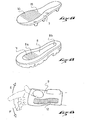
  • FIG. 19 shows wrist protection especially for skateboarding, snowboarding or roller skating, incorporating on its underside, an insert 12 according to the invention.
  • this insert 12 is preferably disposed on the inner side thereof in an area which from the end of the forearm extends into the palm of the hand.
  • the insert 12 leaves free flexion F wrist 9 but prevents its hyper-extension E, which is a major cause of accident in these sports practices.
  • the insert is 'returned' with respect to the first type, that is to say, it allows the extension E but forbids the flexion F.
  • inserts arranged in these two types of protection will present in a neutral position a curve, thus ensuring a better comfort.
  • FIG. 20 represents an alpine ski boot 30 which is equipped at the rear with an insert 13 according to the invention.
  • the main bending lines 6 of the insert 13 are horizontal to allow flexion F to the front of the leg.
  • Bending lines 63 are arranged substantially vertically to allow flexion lateral FL limited.
  • the complementary flexion lines 63 are curved to reduce, at the upper and lower ends of the insert 13, the angle that these make with the main bending lines 6, which are substantially horizontal.
  • the lateral flexion FL is particularly interesting for alpine ski boots especially those dedicated to new gliding, among which are very short skis or 'snowblade'.
  • Such a construction is compatible with shoe constructions of so-called type, front entry, rear entry or hybrid.
  • such an insert can be used in the shaft of any other type of shoe, having areas where flexures are desired in one direction.
  • FIG. 21 represents a snowboard binding 32 whose rear support 31, or spoiler, is equipped with an insert 14 according to the invention.
  • flexing F is allowed forward thanks to the main bending lines 6, but it is forbidden rearward. If necessary, it will be possible to provide complementary flexion lines 64 which allow limited FL lateral flexion.
  • FIGS. advantageously be energized by the appearance of a third layer of elastic material such as as described in Figure 13.
  • the present invention applies in particular to any structure for which it is desired to flexibility in one direction, but stiffness in the opposite direction.

Landscapes

  • Engineering & Computer Science (AREA)
  • Health & Medical Sciences (AREA)
  • General Health & Medical Sciences (AREA)
  • Physical Education & Sports Medicine (AREA)
  • Chemical & Material Sciences (AREA)
  • Materials Engineering (AREA)
  • Life Sciences & Earth Sciences (AREA)
  • Wood Science & Technology (AREA)
  • Mechanical Engineering (AREA)
  • Textile Engineering (AREA)
  • Footwear And Its Accessory, Manufacturing Method And Apparatuses (AREA)

Abstract

Structure composite comprenant au moins une surface, ladite structure autorisant la flexion selon un côté de ladite surface et interdisant la flexion selon le côté opposé ou contre-flexion; ladite structure comprenant; une première couche (1) flexible mais sensiblement non extensible; et une deuxième couche (2) fixée sur la première comprenant une pluralité d'éléments (20) juxtaposés résistants au moins à des efforts de compression exercés suivant une direction sensiblement parallèle à la dite structure. De préférence, ladite structure composite comprend des moyens d'énergisation, qui augmentent la force de rappel en position neutre, ceux-ci pouvant être constitués par une troisième couche (3) faite d'un matériau élastique. <IMAGE>

Description

La présente invention concerne une structure composite essentiellement bidimensionnelle autorisant la flexion et interdisant la contre-flexion.
Le document DE 35 16 545 décrit un gant pour gardien de but de football dans lequel une structure souple/rigide est utilisée. Cette structure est composée de deux couches, une couche intérieure qui est flexible et d'une deuxième couche composée d'une pluralité d'éléments fixés sur la première couche. L'objectif recherché par une telle construction est de protéger les doigts du gardien de but lorsqu'il réceptionne le ballon et de transmettre les efforts générés lors de la réception du ballon des doigts jusque dans le poignet. Cette construction est spécialement adaptée pour un gant. Ainsi, pour laisser au joueur une grande liberté de positionnement de ses doigts (plus ou moins fléchis) la première couche peut fléchir mais ne doit pas exercer une très grande force de rappel, laquelle force de rappel tendrait inévitablement à ramener les doigts en position hyper-étendue. Le port des gants serait dans ce cas très inconfortable. Il est donc important que cette structure ne présente qu'une faible élasticité.
Une telle structure ne peut être utilisée dans la construction d'une semelle de chaussure de sport. En effet, il est préférable pour un article de sport d'avoir une semelle qui revient à sa position initiale après déformation.
Le document FR 2 527 428 décrit une structure de ce type spécialement adaptée pour une semelle de chaussure de football. Elle est composée de parties en matière de grande dureté directement adjacentes entre elles, qui sont fixées sous une couche de matière molle. La flexibilité est assurée grâce à la flexion de la matière molle. La contre-flexion, c'est-à-dire la flexion vers le bas, est restreinte dès que les parties rigides entrent en contact les unes avec les autres. Cependant si l'effort de contre-flexion dépasse une certaine valeur la matière molle s'allongera et la semelle fléchira vers le bas. Une telle structure ne résout donc que partiellement le problème d'interdire la contre-flexion.
Le document FR 889 147 décrit une semelle de chaussure composée d'une planche en contre-plaqué sous laquelle sont fixés des éléments profilés rigides constitués d'une seule pièce de bois naturel. Les différentes sections de profilés envisagés aux figures 1, 4, 9 et 10 sont choisies pour éviter le blocage de petits cailloux dans les intervalles et la résistance à une compression exercée suivant l'axe longitudinal de la semelle sur l'ensemble de ces éléments s'en trouve de ce fait amoindrie. La résistance à la contre-flexion n'est nullement envisagée dans ce document, mais on peut déduire de ce qui précède quelle sera faible.
Le but de la présente invention est de remédier aux inconvénients des structures existantes, en particulier de construire une structure élastique perfectionnée qui à partir d'une position stable autorise la flexion dans une première direction ou selon un premier côté et interdit la contre-flexion, c'est-à-dire la flexion dans la direction opposée, que l'on nommera ici deuxième direction ou deuxième côté.
Ce but est atteint dans la structure composite revendiquée à la revendication 1. Il s'agit d'une structure composite comprenant au moins une surface autorisant la flexion selon un premier côté et interdisant la flexion de l'autre côté, ou deuxième côté (contre-flexion), ladite structure comprenant une première couche faite d'un matériau flexible mais sensiblement non extensible et une deuxième couche, fixée sous celle-ci et qui comprend une pluralité d'éléments juxtaposés résistants au moins à des efforts de compression exercés suivant une direction sensiblement parallèle à ladite structure. Du fait de cette construction, la structure pourra librement fléchir du côté de la première couche car les éléments de la deuxième couche se sépareront les uns des autres. En revanche la flexion du côté de la deuxième couche, c'est-à-dire la contre-flexion, sera impossible dès que les éléments de la deuxième couche entreront en contact. En effet, l'inextensibilité de la première couche combinée à l'incompressibilité des éléments formant la deuxième couche rigidifie complètement la structure en contre-flexion.
Dans un mode de réalisation préférentiel, la structure comprend des moyens d'énergisation augmentant la force de rappel en position neutre. Ces moyens d'énergisation peuvent prendre plusieurs formes. Une de ces formes consiste à mettre en précontrainte en flexion selon la première direction la première couche. Ainsi, en position neutre ou de repos, la structure est énergisée, c'est-à-dire en l'occurrence sollicitée en flexion selon la première direction. Une autre forme consiste à fixer sur la deuxième couche une troisième couche faite d'un matériau très élastique.
De préférence, la première couche est fine et constituée d'un matériau à haut module d'élasticité. Il peut s'agir d'une lame métallique ou d'un matériau composite haute performance, comme par exemple un tissu de verre, imprégné ou non de résine. C'est la finesse de cette couche qui autorisera la flexion de la structure.
En revanche, la deuxième couche est de préférence plus épaisse car la résistance à la contre-flexion de la structure est déterminée par la résistance à la compression de cette couche, laquelle est approximativement proportionnelle au cube de son épaisseur. Afin de ne pas alourdir la structure, on préférera des matériaux légers comme le bois ou une mousse rigide qui résiste très bien à la compression.
On le comprend aisément, une telle structure peut être utilisée dans de nombreuses applications. Certaines de ces applications se trouvent dans les matériels sportifs comme les chaussures, les dispositifs de protections corporelles ou les dispositifs de fixation d'une chaussure sur un engin de glisse.
La présente invention concerne également les caractéristiques qui ressortiront de la description qui va suivre en référence au dessin annexé, montrant à titre d'exemple quelques modes de réalisation, et dans lequel :
  • la figure 1 est une vue en coupe longitudinale d'une portion de structure composite selon un premier mode de réalisation de l'invention,
  • la figure 2 est une vue similaire à la figure 1 montrant la même structure en position fléchie,
  • la figure 3 est vue de dessous de la même structure en position fléchie,
  • la figure 4 est une vue de dessus d'une variante du premier mode de réalisation de l'invention,
  • la figure 5 est une vue en perspective d'une structure selon un deuxième mode de réalisation de l'invention de l'invention,
  • les figures 6 à 8 sont des vues similaires à la figure 5 montrant le fonctionnement de la structure selon le deuxième mode de réalisation de l'invention,
  • les figures 9 et 10 sont des vues en coupe longitudinale d'un troisième et quatrième mode de réalisation de l'invention,
  • les figures 11 et 12 sont des vues en coupe longitudinale illustrant une première forme d'énergisation d'une structure selon l'invention,
  • la figure 13 est vue en coupe longitudinale illustrant une deuxième forme d'énergisation d'une structure selon l'invention,
  • la figure 14 est une vue en perspective avec arraché partiel d'une semelle utilisant une structure composite selon l'invention,
  • les figures 15-18 illustrent des exemples d'utilisation d'une structure composite selon l'invention au sein d'une semelle de chaussure,
  • la figure 19 montre une protection de poignet utilisant la structure de l'invention,
  • la figure 20 est une vue en perspective arrière d'une chaussure de ski utilisant la structure de l'invention,
  • la figure 21 est une vue en perspective arrière d'une fixation de snowboard utilisant la structure selon l'invention,
  • la figure 22 est une vue partielle en coupe longitudinale d'une structure selon un autre mode de réalisation de l'invention,
  • la figure 23 est une vue de dessous d'une structure selon l'invention dont les lignes de flexion sont de profil variés,
  • la figure 24 est une vue en coupe longitudinale d'une structure selon l'invention dont les cales présentent des section variées,
  • la figure 25 est une vue en perspective arrière d'un patin à roulette la structure selon l'invention.
Les figures 1 et 2 représentent une coupe longitudinale de la structure selon un premier mode de réalisation de l'invention. La première couche 1 est une lame flexible d'épaisseur faible et ayant un haut module d'élasticité, donc sensiblement non extensible. On choisira un matériau dont le module d'élasticité est compris de préférence entre 10.000 et 100.000 MPa (Megapascal). Ce peut être une lame métallique ou bien un tissu hautes performances. La deuxième couche 2 se compose de blocs allongés 20, sensiblement incompressibles, disposés transversalement par rapport à la direction longitudinale de la structure et qui sont juxtaposés et collés sous la première couche 1. Les plans de contact P entre les différents blocs allongés 20 sont parallèles entre eux et perpendiculaires à la structure. Ces plans définissent des lignes de flexion 6 (cf. fig. 3) s'étendant transversalement à la direction longitudinale de la structure.
La figure 2 montre la même structure en position fléchie. La première couche 1 subit une flexion selon une première direction F, tandis que les blocs 20 s'écartent les uns des autres. Il est à noter que la figure 1, quant à elle, montre la structure à la fois dans sa position neutre, c'est-à-dire soumise à aucun effort extérieur, et dans une position soumise à un effort de contre-flexion. Dans ce dernier cas, la flexion de la lame 1 dans la direction de contre-flexion C, opposée à la direction de flexion F, est bloquée dès que les blocs 20 entrent en contact les uns avec les autres. On obtient alors une structure très rigide. Cette rigidité est autorisée par l'inextensibilité de la première couche 1 combinée à la incompressibilité des blocs allongés 20.
La pluralité d'éléments de la deuxième couche n'est pas nécessairement constituée de blocs 20 de forme allongée. La figure 4 montre une vue de dessous partielle d'une variation du premier mode réalisation de l'invention dans laquelle les éléments sont des blocs sensiblement cubiques ou parallélépipèdiques 20 disposés de façon à définir des lignes de flexion 6 parallèles entre elles et sensiblement transversales à une direction longitudinale L de la structure.
Dans le deuxième mode de réalisation représenté aux figures 5 à 8, on prévoit de disposer les blocs 20 de telle façon que deux groupes de lignes de flexion 61, 62, perpendiculaires entre eux, soient définis. On peut ainsi bénéficier d'une flexibilité dans deux directions (cf. figures 6, 7). Dans le cas de petites déformations, la structure pourra fléchir dans les deux directions simultanément (figure 8). Dans ce mode de réalisation, les lignes de flexion 61, 62, sont droites et perpendiculaires entre elles. Cependant pour certaines applications il sera plus intéressant de donner à ces lignes de flexion des contours particuliers et de faire varier l'angle que font entre eux, les deux groupes de lignes de flexion, ledit angle pouvant prendre toute valeur comprise entre 10° et 90°, notamment 45°. Ces aspects seront décrit plus loin dans la description, notamment en relation avec l'utilisation de la structure selon l'invention dans la construction d'une tige de chaussure de sport ou d'une fixation de chaussure sur un engin de glisse.
La figure 9 décrit un troisième mode de réalisation dans lequel pour améliorer les performances, les éléments de la deuxième couche 2 sont constitués de barrettes 21 faites d'un matériau léger tel que décrit en référence aux figures 1 et 2 entre lesquelles on dispose des cales 4 de matière très rigide. La résistance à la compression de la deuxième couche 2 est ainsi améliorée sans pour autant alourdir considérablement la structure.
Dans un quatrième mode de réalisation de l'invention (cf. fig. 10), pour améliorer le comportement mécanique général de la structure, les éléments constituants la deuxième couche 2 sont des éléments multicouches 22. Pour ce faire, on donne à la deuxième couche une peau 5 très résistante. Cette peau peut consister en une lame similaire à la première couche 1 qui est collée à la deuxième couche et est ensuite découpée. Une telle structure, représentée à la figure 10, a en contre-flexion et en torsion la rigidité d'une structure sandwich haute performance, tout en gardant la possibilité de flexion vers le haut (direction F).
Dans un cinquième mode de réalisation de l'invention, une partie des éléments de la deuxième couche 2 sont reliés entre eux simplement parce qu'ils constituent des parties 24 faisant saillie d'une même pièce 25. La figure 22 représente partiellement une structure selon ce mode de réalisation. Une partie des éléments constituant la deuxième couche 2 forment une structure en créneaux 24 qui sera complétée par des cales 4 telles quelles sont décrites en référence à la figure 9. Une telle construction permet une fabrication en série de la structure selon l'invention. Il suffit en effet de coller un noyau monobloc 25 fait d'un matériau résistant à la compression sur une lame 1 faite d'un matériau à haut module d'élasticité. On vient ensuite usiner des rainures parallèles 26 dans ce noyau 25 afin de définir des éléments distincts 24 et on comble lesdites rainures avec des cales 4.
De manière avantageuse la structure selon l'invention possède des moyens d'énergisation qui augmentent la force de rappel en position neutre.
Une première méthode d'énergisation de la structure, mise en évidence dans les figures 11 et 12, consiste à précontraindre la première couche, ce faisant on donne à la structure un galbe. Pour ce faire, on sépare en deux phases le processus d'assemblage des éléments constituant la deuxième couche. Après avoir fixé sous la première couche 1 des blocs 23 en laissant un intervalle 26 entre deux blocs consécutifs, ce qui constitue la première phase de l'assemblage, on vient lors d'une deuxième phase d'assemblage, insérer dans cet intervalle 26 une cale 4 de largeur plus importante que ledit intervalle qui tend à écarter deux blocs consécutifs 23 l'un de l'autre (cf. figure 11). De préférence, entre les deux phases on fléchit la première couche pour faciliter l'insertion des cales 4. On obtient ainsi une structure qui en position neutre est galbée, ce qui a pour conséquence de précontraindre la première couche 1 dans la direction de flexion F (cf. figure 12). Il s'agit là bien évidemment d'un exemple non limitatif de mise en précontrainte de la première couche. On pourra cependant choisir toute autre méthode de mise en précontrainte de la première couche, y compris des méthodes dans lesquelles la deuxième couche est mise en précontrainte préalablement à son assemblage avec la première, ou encore des méthodes impliquant des variations de température lors des différentes phases d'assemblage.
La possibilité d'avoir une structure souple/rigide qui possède au repos, une position stable non plane est l'un des avantages de l'invention par rapport à l'état de la technique. Cet aspect de l'invention est particulièrement intéressant lorsqu'il s'agit de construire des éléments galbés notamment pour des tiges ou semelles de chaussure tels que chaussure de ski, de snowboard, de patin à roulette.
Une autre manière d'énergiser la structure est décrite en référence à la figure 13. Elle consiste en l'application sous la deuxième couche 2 d'une troisième couche 3, celle-ci étant faite d'un matériau très élastique. De préférence, cette troisième couche 3 est fixée à la deuxième couche par collage. Dans ce cas, la troisième couche 3 exerce une force de rappel dans la direction de contre-flexion C. Dans le cas où la première couche 1 est une lame métallique ou composite, il s'agit d'une énergisation qui complétera la force de rappel créée lors de la flexion de la lame selon la direction F. Dans le cas où la première couche 1 est en un matériau non élastique, cette énergisation est nécessaire pour ramener la structure en position neutre.
Pour augmenter encore l'énergisation, on collera cette troisième couche sous tension, c'est-à-dire déjà étirée. L'intérêt d'une telle énergisation est de garantir un retour à une position neutre même après de multiples flexions et donc de remédier aux problèmes de déformation permanente liée à la fatigue.
Bien entendu, chacune de ces 2 manières d'énergisation de la structure peut s'appliquer aux différents modes de réalisation de l'invention précédemment décrits.
On a décrit jusqu'à présent des structures ayant des lignes de flexion 6 droites et parallèles entre elles. Cependant afin d'obtenir des performances et des comportements variables, on pourra donner à ces lignes 6 des profils variables. La figure 23 montre schématiquement une structure selon l'invention dans laquelle les lignes de flexion 6 ont des profils variés. De même, les cales 4 utilisées dans certains modes de réalisation peuvent avoir des sections variées (figure 24). La direction de ces lignes 6 de flexion pourra être aussi bien transversale que longitudinale à la structure sans sortir pour autant du cadre de la présente invention.
Les figures 14-18 représentent des semelles de chaussure 10 utilisant la structure composite de l'invention. Dans le mode de réalisation de la figure 14, la première couche 1 constitue la partie supérieure de la semelle 10, la seconde couche 2 est constituée d'une pluralité de barrettes 21 définissant des lignes de flexion 6 et recouvertes sur leur face inférieure d'une peau rigide 5 faite du même matériau que la première couche. Entre deux barrettes 21 consécutives est disposée une cale 4. Enfin, une troisième couche d'un matériau élastique 3, collée sur la face inférieure de la couche 2, énergise la structure. Une telle semelle 10 pourra donc fléchir selon les lignes de flexion 6 dans la direction F, par exemple lors de la marche pour permettre le déroulement du pied. En revanche toute contre-flexion C sera impossible et permettra donc une application particulièrement intéressante notamment aux chaussures de football. Dans un tel cas les lignes de flexion 6 sont bien entendu disposées sensiblement transversalement à la direction longitudinale de la semelle. Elles peuvent être disposées avec une inclinaison correspondant à celle de l'articulation métatarsophalangienne. Une telle structure de semelle peut être utilisée comme première de montage ou comme semelle intermédiaire dans une semelle externe, celle-ci étant alors complétée par une semelle caoutchouc ou similaire. De façon connue, on complétera cette semelle d'une première de montage sur le dessus et d'une semelle caoutchouc pour le contact avec le sol.
Dans les quatre modes de réalisation préférés qui suivent (fig. 15-18), la structure ne constitue qu'un insert qui est noyé dans la semelle de la chaussure. Dans un premier mode de réalisation (figure 16), la structure selon l'invention occupera toute la superficie de la semelle, assurant ainsi une flexibilité sous l'ensemble du pied. Dans un mode préféré (figures 14, 15), la structure occupe également toute la superficie de la semelle mais on ne dispose des barrettes 21 et des cales 4 que dans la zone d'articulation métatarsophalangienne. La flexibilité de la chaussure sera donc limitée à cette zone tandis que la rigidité en contre-flexion sera assurée sur toute la semelle.
La figure 17 montre la semelle 15 d'une chaussure de sport dans laquelle on place un insert 10 de la structure souple/rigide selon l'invention. Il s'agit d'un insert similaire à celui décrit figure 14 à la différence qu'il n'occupe pas en largeur la totalité de la semelle mais seulement la partie extérieure ou latérale de celle-ci. On obtient ainsi une semelle très rigide en contre-flexion, capable de fléchir pour suivre le déroulement naturel du pied. Dans la partie médiale, une zone 7 relativement plus souple que l'insert permettra une meilleure prise d'appui lors des phases d'accélération. Une telle semelle sera particulièrement adaptée à la pratique du football.
La figure 18 montre également une semelle de chaussure de sport dans laquelle l'insert 11 selon l'invention est placé centralement. De part sa rigidité dans la zone 8 joignant la zone d'articulation métatarsophalangienne 8a à la zone talon 8b, cet insert rigidifie également la semelle en torsion, ceci sera particulièrement vrai si on choisi un insert tel que décrit en référence à la figure 10.
La structure selon l'invention se révèle également particulièrement intéressante pour la fabrication des protections corporelles. La figure 19 représente une protection de poignet notamment pour la pratique du skateboard, du snowboard ou du patin à roulettes, incorporant sur sa face inférieure, un insert 12 selon l'invention. Afin de protéger l'articulation du poignet on dispose de préférence cet insert 12 sur le côté intérieur de celui-ci dans une zone qui partant de l'extrémité de l'avant bras se prolonge jusque dans la paume de la main. Pour répondre à des pratiques sportives et des besoins différents deux types de protection de poignet ont été envisagés. Dans le premier type, l'insert 12 laisse libre la flexion F du poignet 9 mais empêche son hyper-extension E, ce qui est une cause majeure d'accident dans ces pratiques sportives. Dans le deuxième type, l'insert est 'retourné' par rapport au premier type, c'est-à-dire qu'il autorise l'extension E mais interdit la flexion F. Dans ce dernier cas, afin d'empêcher un accident d'hyper-extension du poignet, on pourra donner une très grande élasticité à l'insert en l'énergisant tel que cela a été précédemment décrit. De préférence, les inserts disposé dans ces deux types de protection présenteront en position neutre un galbe, assurant ainsi un meilleur confort.
La figure 20 représente une chaussure de ski alpin 30 qui est équipée à l'arrière d'un insert 13 selon l'invention. Dans ce cas, les lignes de flexion principales 6 de l'insert 13 sont horizontales pour permettre la flexion F vers l'avant de la jambe. Des lignes de flexion complémentaires 63 sont disposées sensiblement verticalement pour permettre une flexion latérale FL limitée. On remarquera que les lignes de flexion complémentaires 63 sont incurvées afin de réduire, aux extrémités supérieures et inférieures de l'insert 13, l'angle que celles-ci font avec les lignes de flexion principales 6, qui elles sont sensiblement horizontales. L'utilisation d'un tel insert dans une chaussure de ski alpin permet de garantir une rigidité complète dans la direction de contre-flexion C et donc de garantir un bon appui arrière tout en permettant la flexion vers l'avant. Dans une moindre mesure et de façon complémentaire la flexion latérale FL se révèle particulièrement intéressante pour des chaussures de ski alpin notamment celles dédiées aux nouvelles glisses parmi lesquelles on compte les ski très courts ou 'snowblade'. Une telle construction est compatible avec des constructions de chaussure de type dits, entrée avant, entrée arrière ou hybride. Bien entendu un tel insert peut être utilisé dans la tige de tout autre type de chaussure, ayant des zones où des flexions sont souhaitées dans une seule direction.
Ce qui vient d'être décrit pour une chaussure de ski alpin se transpose évidemment à toute chaussure utilisé dans les sports de glisse. Par exemple, dans le cas d'un patin à roulette 33, on intégrera l'insert 15 selon l'invention dans le collier de serrage 34 de la cheville afin de bloquer la flexion arrière de l'articulation de la cheville.
La figure 21 représente une fixation de snowboard 32 dont l'appui arrière 31, ou spoiler, est équipé d'un insert 14 selon l'invention. Comme dans le cas d'une chaussure de ski, la flexion F est autorisée vers l'avant grâce aux lignes de flexion principales 6, mais elle est interdite vers l'arrière. Le cas échéant on pourra prévoir des lignes de flexion complémentaires 64 qui permettront une flexion latérale FL limitée.
Bien entendu les différents modes de réalisation détaillés ci-dessus ne le sont qu'à titre d'exemple et toute combinaison des différentes caractéristiques entre elles est envisageable et couverte par la présente invention. Ainsi une structure décrite aux figures 5 à 8 pourra avantageusement être énergisée par l'aspect d'une troisième couche de matière élastique telle que décrite à la figure 13.
La présente invention s'applique notamment à toute structure pour laquelle on souhaite une flexibilité dans une certaine direction, mais une raideur dans la direction opposée.

Claims (26)

  1. Structure composite comprenant au moins une surface, ladite structure comprenant :
    une première couche (1) en un matériau flexible mais sensiblement non extensible,
    une deuxième couche (2) fixée sur la première comprenant une pluralité d'éléments (20) juxtaposés résistants au moins à des efforts de compression exercés suivant une direction sensiblement parallèle à ladite structure,
       ladite structure ayant une position neutre dans laquelle la pluralité d'éléments sont en contact les uns avec les autres,
       ladite structure pouvant fléchir selon une première direction (F), tandis que les éléments s'écartent les uns des autres,
       lesdits éléments (20) empêchant une contre-flexion de la structure dans une seconde direction (C) opposée, au delà de la position neutre, caractérisée en ce que ladite structure comprend des moyens d'énergisation augmentant la force de rappel en position neutre, et en ce que les moyens d'énergisation sont constitués par une troisième couche élastique fixée sur la deuxième couche à l'opposé de la première couche.
  2. Structure composite selon la revendication 1, caractérisée en ce que la première couche (1) est beaucoup plus fine que la deuxième (2).
  3. Structure composite selon la revendication 1 ou 2, caractérisée en ce que la troisième couche (3) est constituée d'un matériau élastique.
  4. Structure composite selon l'une des revendications 1 à 3, caractérisée en ce que la troisième couche (3) est constituée de caoutchouc.
  5. Structure composite selon l'une des revendications 1 à 4, caractérisée en ce que la pluralité d'éléments (20) est arrangée sous la forme d'une juxtaposition définissant au moins des lignes de flexion (6).
  6. Structure composite selon l'une des revendications 1 à 5, caractérisée en ce que la pluralité d'éléments (20) comprend des éléments de forme sensiblement allongée, appelés blocs allongés (21, 22, 23, 24, 4).
  7. Structure composite selon l'une des revendications 1 à 6, caractérisée en ce que la pluralité d'éléments (20) comprend des éléments reliés entre eux.
  8. Structure composite selon la revendication 7, caractérisée en ce que lesdits éléments reliés entre eux le sont par leur côté adjacent à la première couche (1).
  9. Structure composite selon l'une des revendications 7 à 8, caractérisée en ce que lesdits éléments reliés entre eux constituent des parties (24) faisant saillie d'une même pièce (25).
  10. Structure composite selon l'une des revendications 1 à 9, caractérisée en ce que la pluralité d'éléments (20) comprend des éléments de formes et de matériaux différents.
  11. Structure composite selon l'une des revendications 1 à 10, caractérisée en ce que la pluralité d'éléments comprend des éléments multicouches (22).
  12. Structure composite selon la revendication 11, caractérisée en ce que lesdits éléments multicouches (22) comprennent une peau (5) disposée sur la face extérieure desdits éléments.
  13. Structure composite selon la revendication 12, caractérisée en ce que ladite peau (5) est constituée du même matériau que la première couche (1).
  14. Structure composite selon l'une des revendications 1 à 13, caractérisée en ce que les lignes de flexion (6) sont toutes sensiblement parallèles.
  15. Structure composite selon l'une des revendications 1 à 14, caractérisée en ce que les lignes de flexion (6) se regroupent en plusieurs groupes (61, 62), au sein desquels les lignes sont sensiblement parallèles entre elles.
  16. Structure composite selon la revendication 15, caractérisée en ce que les groupes de lignes de flexion font entre eux un angle aigu.
  17. Structure composite selon l'une des revendications 15 ou 16, caractérisée en ce que les lignes de flexion se regroupent en deux groupes (61, 62) faisant entre eux un angle sensiblement perpendiculaire.
  18. Structure composite selon l'une des revendications 15 ou 16, caractérisée en ce que les lignes de flexion se regroupent en deux groupes faisant entre eux un angle d'une valeur sensiblement égale à 45 degré.
  19. Structure composite selon l'une des revendications 1 à 18, caractérisée en ce que lorsque la structure est en position neutre, la première couche (1) est maintenue en précontrainte.
  20. Structure composite selon l'une des revendications 1 à 19, caractérisée en ce que la structure est galbée.
  21. Structure composite selon la revendication 20, caractérisée en ce que le galbe est obtenu par un montage qui comprend deux phases distinctes d'assemblage de deux groupes d'éléments (21, 4) sur la première couche et en ce qu'entre les deux phases d'assemblage, une flexion de la plaque est opérée.
  22. Structure composite selon l'une des revendications 1 à 21, caractérisée en ce qu'elle est intégrée dans une semelle de chaussure et en ce que les lignes de flexion (6) sont sensiblement perpendiculaires à l'axe longitudinal de la semelle.
  23. Structure composite selon la revendication 22, caractérisée en ce que les lignes de flexion ne sont présentes que dans la zone correspondant à la zone d'articulation métatarsophalangienne.
  24. Structure composite selon l'une quelconque des revendications 1 à 23, caractérisée en ce que le matériau de la première couche a un module d'élasticité compris entre 10.000 et 100.000 MPa.
  25. Semelle de chaussure caractérisée en ce que elle comprend au moins une structure selon l'une des revendications 1 à 24.
  26. Semelle selon l'une des revendications 24 à 25, caractérisée en ce que la structure a une superficie sensiblement égale à celle de la semelle.
EP05010571A 1999-08-03 2000-07-06 Structure souple-rigide Withdrawn EP1561390A1 (fr)

Applications Claiming Priority (3)

Application Number Priority Date Filing Date Title
FR9910219A FR2797214B1 (fr) 1999-08-03 1999-08-03 Structure souple - rigide
FR9910219 1999-08-03
EP00114500A EP1074194A1 (fr) 1999-08-03 2000-07-06 Structure souple - rigide

Related Parent Applications (1)

Application Number Title Priority Date Filing Date
EP00114500A Division EP1074194A1 (fr) 1999-08-03 2000-07-06 Structure souple - rigide

Publications (1)

Publication Number Publication Date
EP1561390A1 true EP1561390A1 (fr) 2005-08-10

Family

ID=9548950

Family Applications (2)

Application Number Title Priority Date Filing Date
EP05010571A Withdrawn EP1561390A1 (fr) 1999-08-03 2000-07-06 Structure souple-rigide
EP00114500A Withdrawn EP1074194A1 (fr) 1999-08-03 2000-07-06 Structure souple - rigide

Family Applications After (1)

Application Number Title Priority Date Filing Date
EP00114500A Withdrawn EP1074194A1 (fr) 1999-08-03 2000-07-06 Structure souple - rigide

Country Status (4)

Country Link
EP (2) EP1561390A1 (fr)
JP (1) JP2001070005A (fr)
CN (1) CN1282551A (fr)
FR (1) FR2797214B1 (fr)

Cited By (1)

* Cited by examiner, † Cited by third party
Publication number Priority date Publication date Assignee Title
US8522457B2 (en) 2008-12-23 2013-09-03 Adidas International Marketing B.V. Sole

Families Citing this family (24)

* Cited by examiner, † Cited by third party
Publication number Priority date Publication date Assignee Title
FR2823078B1 (fr) * 2001-04-09 2003-06-27 Salomon Sa Renfort de chaussure, en particulier de sport, et chaussure comprenant un tel renfort
DE20107098U1 (de) * 2001-04-25 2002-10-02 Hochmuth, Peter, 91757 Treuchtlingen Versteifungsstreifen für einen Torwarthandschuh
US8549774B2 (en) 2005-11-15 2013-10-08 Nike, Inc. Flexible shank for an article of footwear
US8225534B2 (en) 2005-11-15 2012-07-24 Nike, Inc. Article of footwear with a flexible arch support
US7686321B2 (en) 2006-12-01 2010-03-30 The Burton Corporation Highback with textile-like material for support
GB0702182D0 (en) * 2007-02-05 2007-03-14 Tomlinson Rachel Dynamically self-enclosing footwear
DE202008017725U1 (de) * 2008-04-25 2010-05-12 Vaude Gmbh & Co. Kg Schuh oder Versteifungselement für Rucksäcke
AT508426B1 (de) 2009-06-17 2011-12-15 Atomic Austria Gmbh Sportschuh mit einer äusseren schale aus formgespritztem kunststoff
JP5474427B2 (ja) * 2009-07-13 2014-04-16 株式会社 一歩 履物中敷
WO2013096977A1 (fr) * 2011-10-17 2013-06-27 Stratford Aloth Usher Matériau stratifié flexible
ITRM20110592A1 (it) * 2011-11-09 2012-02-08 Antonelli Marcello Elemento multistrato flessibile preferibilmente in legno e relativo procedimento di produzione tramite incisione e/o taglio a mezzo laser
JP6196471B2 (ja) * 2012-10-26 2017-09-13 モリト株式会社 サポータ
EP2742818B1 (fr) * 2012-12-12 2017-01-18 Mike-Martin Robacki Système de fonctionnement de semelle vertébrale / semelle intérieure, en particulier pour pointes de danse classique
ITTV20130108A1 (it) * 2013-07-11 2015-01-12 Scarpa Calzaturificio Spa Sottopiede rigido per calzature e calzatura provvista di tale sottopiede
DE102014008580B4 (de) 2014-06-17 2024-09-05 Vaude Gmbh & Co. Kg Flächiges Versteifungselement insbesondere für Rucksäcke
PL3250375T3 (pl) 2015-01-28 2022-11-21 Composite Research S.R.L. Panel z materiału kompozytowego, mający strukturę warstwową
US10226097B2 (en) * 2015-09-18 2019-03-12 Nike, Inc. Footwear sole structure with nonlinear bending stiffness
JP7075032B2 (ja) * 2016-04-04 2022-05-25 有限会社スワニー 緩衝材の製造方法
DE102016211118A1 (de) * 2016-06-22 2017-12-28 Arno Trénel Sportschuh
CN107215405B (zh) * 2017-05-12 2019-05-10 南京航空航天大学 一种具有自适应能力的弹性脚掌结构
DE102019102107A1 (de) * 2019-01-29 2020-07-30 Reinhardt UG i.G. Sohlenvorrichtung
US11944158B2 (en) 2019-09-03 2024-04-02 Adidas Ag Sole element
CN112438463B (zh) * 2019-09-03 2022-05-10 阿迪达斯股份公司 鞋底元件
CN117158672A (zh) * 2023-09-07 2023-12-05 安踏(中国)有限公司 一种具有区块化结构的布料及其所做的护具材料

Citations (7)

* Cited by examiner, † Cited by third party
Publication number Priority date Publication date Assignee Title
CH88539A (fr) * 1920-02-26 1921-03-01 D Aprea Salvatore Semelle pour chaussures.
FR889147A (fr) 1942-05-22 1943-12-31 Semelle flexible entièrement en bois
FR2527428A1 (fr) 1982-05-26 1983-12-02 Uhl Sportartikel Karl Semelle pour chaussure de sport, notamment pour chaussure de football
DE3516545A1 (de) 1985-05-08 1986-11-13 Endrik 8061 Weichs Fleischmann Handschuh, insbesondere torwarthandschuh
US5488739A (en) * 1994-12-15 1996-02-06 Itech Sport Products, Inc. Hockey glove construction
US5745916A (en) * 1994-02-24 1998-05-05 Linner; Hans Protective glove for ice-hockey and similar sports
WO2000053275A1 (fr) * 1999-03-11 2000-09-14 Reusch International Gmbh & Co. Kg Gant de sport, notamment gant de gardien de but

Family Cites Families (6)

* Cited by examiner, † Cited by third party
Publication number Priority date Publication date Assignee Title
DE315082C (fr) * 1900-01-01
FR898720A (fr) * 1943-06-02 1945-05-04 Patins et semelles articulés pour chaussures
US5269079A (en) * 1992-03-04 1993-12-14 Kunstadt Robert M Ski footwear
IT1279260B1 (it) * 1995-01-31 1997-12-09 Nordica Spa Dispositivo di supporto, particolarmente per calzature sportive
US5600849A (en) * 1995-07-07 1997-02-11 Hu; Antonio C. Wrist guard
IT1304713B1 (it) * 1998-05-28 2001-03-29 Tonelli S R L Suola articolata per zoccoli, sandali ed altre calzature.

Patent Citations (7)

* Cited by examiner, † Cited by third party
Publication number Priority date Publication date Assignee Title
CH88539A (fr) * 1920-02-26 1921-03-01 D Aprea Salvatore Semelle pour chaussures.
FR889147A (fr) 1942-05-22 1943-12-31 Semelle flexible entièrement en bois
FR2527428A1 (fr) 1982-05-26 1983-12-02 Uhl Sportartikel Karl Semelle pour chaussure de sport, notamment pour chaussure de football
DE3516545A1 (de) 1985-05-08 1986-11-13 Endrik 8061 Weichs Fleischmann Handschuh, insbesondere torwarthandschuh
US5745916A (en) * 1994-02-24 1998-05-05 Linner; Hans Protective glove for ice-hockey and similar sports
US5488739A (en) * 1994-12-15 1996-02-06 Itech Sport Products, Inc. Hockey glove construction
WO2000053275A1 (fr) * 1999-03-11 2000-09-14 Reusch International Gmbh & Co. Kg Gant de sport, notamment gant de gardien de but

Cited By (1)

* Cited by examiner, † Cited by third party
Publication number Priority date Publication date Assignee Title
US8522457B2 (en) 2008-12-23 2013-09-03 Adidas International Marketing B.V. Sole

Also Published As

Publication number Publication date
EP1074194A1 (fr) 2001-02-07
CN1282551A (zh) 2001-02-07
JP2001070005A (ja) 2001-03-21
FR2797214A1 (fr) 2001-02-09
FR2797214B1 (fr) 2002-11-29

Similar Documents

Publication Publication Date Title
EP1561390A1 (fr) Structure souple-rigide
EP2198729B1 (fr) Chaussure à semelage amélioré
EP0548475B1 (fr) Semelle de chaussure de sport multicouche
EP1536711B1 (fr) Article chaussant pour sports de raquette
EP1100349B1 (fr) Semelle de chaussure
EP1249184B1 (fr) Renfort de chaussure de sport
EP0787440B1 (fr) Semelle pour chaussure de sport
EP1210883B1 (fr) Semelle de chaussure de ski de fond
FR2532529A1 (fr) Chaussure de ski de fond
WO2012114002A2 (fr) Chaussure destinée à la pratique d&#39;un sport de glisse sur neige, ou à la marche
FR2771015A1 (fr) Ame pour planche de glisse
EP3195748B1 (fr) Semelle de chaussure de ski de fond
EP0855201B1 (fr) Planche de glisse
EP2374513B1 (fr) Dispositif d&#39;accueil d&#39;un pied ou d&#39;une chaussure sur un engin de glisse
EP0922473B1 (fr) Noyau pour surf de neige
FR2887178A1 (fr) Element de structure d&#39;une chaussure de sport
EP3037141B1 (fr) Planche de glisse sur neige présentant des chants complexes
EP0661086A1 (fr) Ski
EP1803362B1 (fr) Chaussure de sport à oscillation latérale
FR2726193A1 (fr) Engin de glisse sur neige, tel que ski alpin, ski de fond, monoski, surf
FR2945456A1 (fr) Embout de spatule de planche de glisse
FR3160858A1 (fr) Elément de renfort pour chaussure de sport
FR2823078A1 (fr) Renfort de chaussure, en particulier de sport, et chaussure comprenant un tel renfort
FR2778534A1 (fr) Chaussure de sport a ossature interne rigide
FR2704442A1 (fr) Nouveau type de ski.

Legal Events

Date Code Title Description
PUAI Public reference made under article 153(3) epc to a published international application that has entered the european phase

Free format text: ORIGINAL CODE: 0009012

AC Divisional application: reference to earlier application

Ref document number: 1074194

Country of ref document: EP

Kind code of ref document: P

AK Designated contracting states

Kind code of ref document: A1

Designated state(s): AT BE CH CY DE DK ES FI FR GB GR IE IT LI LU MC NL PT SE

17P Request for examination filed

Effective date: 20051214

AKX Designation fees paid

Designated state(s): AT BE CH CY DE DK ES FI FR GB GR IE IT LI LU MC NL PT SE

STAA Information on the status of an ep patent application or granted ep patent

Free format text: STATUS: THE APPLICATION IS DEEMED TO BE WITHDRAWN

18D Application deemed to be withdrawn

Effective date: 20070201