EP1560787B1 - Mikroelektromechanisches bauteil mit piezoelektrischem dünnfilmaktuator - Google Patents
Mikroelektromechanisches bauteil mit piezoelektrischem dünnfilmaktuator Download PDFInfo
- Publication number
- EP1560787B1 EP1560787B1 EP03786748A EP03786748A EP1560787B1 EP 1560787 B1 EP1560787 B1 EP 1560787B1 EP 03786748 A EP03786748 A EP 03786748A EP 03786748 A EP03786748 A EP 03786748A EP 1560787 B1 EP1560787 B1 EP 1560787B1
- Authority
- EP
- European Patent Office
- Prior art keywords
- layer
- electrode
- thin film
- conducting path
- film actuator
- Prior art date
- Legal status (The legal status is an assumption and is not a legal conclusion. Google has not performed a legal analysis and makes no representation as to the accuracy of the status listed.)
- Expired - Lifetime
Links
- 239000010409 thin film Substances 0.000 title claims abstract description 60
- 239000000758 substrate Substances 0.000 claims abstract description 47
- 238000004519 manufacturing process Methods 0.000 claims abstract description 21
- 239000010410 layer Substances 0.000 claims description 122
- 229910052451 lead zirconate titanate Inorganic materials 0.000 claims description 58
- 239000004020 conductor Substances 0.000 claims description 36
- 239000000463 material Substances 0.000 claims description 21
- 238000000034 method Methods 0.000 claims description 16
- 238000002955 isolation Methods 0.000 claims description 13
- 239000004065 semiconductor Substances 0.000 claims description 12
- 239000011241 protective layer Substances 0.000 claims description 9
- 238000005530 etching Methods 0.000 claims description 7
- BASFCYQUMIYNBI-UHFFFAOYSA-N platinum Chemical compound [Pt] BASFCYQUMIYNBI-UHFFFAOYSA-N 0.000 claims description 7
- 238000000059 patterning Methods 0.000 claims description 6
- HFGPZNIAWCZYJU-UHFFFAOYSA-N lead zirconate titanate Chemical compound [O-2].[O-2].[O-2].[O-2].[O-2].[Ti+4].[Zr+4].[Pb+2] HFGPZNIAWCZYJU-UHFFFAOYSA-N 0.000 claims description 5
- 229910052697 platinum Inorganic materials 0.000 claims description 3
- 230000008602 contraction Effects 0.000 claims description 2
- 239000003990 capacitor Substances 0.000 abstract description 8
- 229920002120 photoresistant polymer Polymers 0.000 description 12
- VYPSYNLAJGMNEJ-UHFFFAOYSA-N Silicium dioxide Chemical compound O=[Si]=O VYPSYNLAJGMNEJ-UHFFFAOYSA-N 0.000 description 10
- 239000010931 gold Substances 0.000 description 10
- 229910052737 gold Inorganic materials 0.000 description 9
- 238000006073 displacement reaction Methods 0.000 description 7
- PCHJSUWPFVWCPO-UHFFFAOYSA-N gold Chemical compound [Au] PCHJSUWPFVWCPO-UHFFFAOYSA-N 0.000 description 7
- 229910001258 titanium gold Inorganic materials 0.000 description 7
- 229910052581 Si3N4 Inorganic materials 0.000 description 6
- XUIMIQQOPSSXEZ-UHFFFAOYSA-N Silicon Chemical compound [Si] XUIMIQQOPSSXEZ-UHFFFAOYSA-N 0.000 description 6
- 229910052710 silicon Inorganic materials 0.000 description 6
- 239000010703 silicon Substances 0.000 description 6
- HQVNEWCFYHHQES-UHFFFAOYSA-N silicon nitride Chemical compound N12[Si]34N5[Si]62N3[Si]51N64 HQVNEWCFYHHQES-UHFFFAOYSA-N 0.000 description 6
- 239000000377 silicon dioxide Substances 0.000 description 5
- 238000005516 engineering process Methods 0.000 description 4
- 235000012239 silicon dioxide Nutrition 0.000 description 4
- 229910001218 Gallium arsenide Inorganic materials 0.000 description 3
- 238000001816 cooling Methods 0.000 description 3
- 230000005684 electric field Effects 0.000 description 3
- 230000015572 biosynthetic process Effects 0.000 description 2
- 239000000919 ceramic Substances 0.000 description 2
- 238000012986 modification Methods 0.000 description 2
- 230000004048 modification Effects 0.000 description 2
- 125000006850 spacer group Chemical group 0.000 description 2
- 238000001039 wet etching Methods 0.000 description 2
- RYGMFSIKBFXOCR-UHFFFAOYSA-N Copper Chemical compound [Cu] RYGMFSIKBFXOCR-UHFFFAOYSA-N 0.000 description 1
- 230000004075 alteration Effects 0.000 description 1
- 238000000429 assembly Methods 0.000 description 1
- 230000000712 assembly Effects 0.000 description 1
- 230000008859 change Effects 0.000 description 1
- VNNRSPGTAMTISX-UHFFFAOYSA-N chromium nickel Chemical compound [Cr].[Ni] VNNRSPGTAMTISX-UHFFFAOYSA-N 0.000 description 1
- 238000004891 communication Methods 0.000 description 1
- 229910052802 copper Inorganic materials 0.000 description 1
- 239000010949 copper Substances 0.000 description 1
- 230000007423 decrease Effects 0.000 description 1
- 238000000151 deposition Methods 0.000 description 1
- 238000009826 distribution Methods 0.000 description 1
- 238000001312 dry etching Methods 0.000 description 1
- 238000010438 heat treatment Methods 0.000 description 1
- 230000005499 meniscus Effects 0.000 description 1
- 239000000203 mixture Substances 0.000 description 1
- 229910001120 nichrome Inorganic materials 0.000 description 1
- 238000007747 plating Methods 0.000 description 1
- 230000008569 process Effects 0.000 description 1
- 238000009877 rendering Methods 0.000 description 1
- 230000004044 response Effects 0.000 description 1
- 238000004544 sputter deposition Methods 0.000 description 1
- 239000007858 starting material Substances 0.000 description 1
- 230000003068 static effect Effects 0.000 description 1
- 239000000126 substance Substances 0.000 description 1
- 229910052715 tantalum Inorganic materials 0.000 description 1
- GUVRBAGPIYLISA-UHFFFAOYSA-N tantalum atom Chemical compound [Ta] GUVRBAGPIYLISA-UHFFFAOYSA-N 0.000 description 1
Images


Classifications
-
- B—PERFORMING OPERATIONS; TRANSPORTING
- B81—MICROSTRUCTURAL TECHNOLOGY
- B81B—MICROSTRUCTURAL DEVICES OR SYSTEMS, e.g. MICROMECHANICAL DEVICES
- B81B3/00—Devices comprising flexible or deformable elements, e.g. comprising elastic tongues or membranes
-
- B—PERFORMING OPERATIONS; TRANSPORTING
- B81—MICROSTRUCTURAL TECHNOLOGY
- B81B—MICROSTRUCTURAL DEVICES OR SYSTEMS, e.g. MICROMECHANICAL DEVICES
- B81B3/00—Devices comprising flexible or deformable elements, e.g. comprising elastic tongues or membranes
- B81B3/0018—Structures acting upon the moving or flexible element for transforming energy into mechanical movement or vice versa, i.e. actuators, sensors, generators
-
- H—ELECTRICITY
- H01—ELECTRIC ELEMENTS
- H01G—CAPACITORS; CAPACITORS, RECTIFIERS, DETECTORS, SWITCHING DEVICES, LIGHT-SENSITIVE OR TEMPERATURE-SENSITIVE DEVICES OF THE ELECTROLYTIC TYPE
- H01G5/00—Capacitors in which the capacitance is varied by mechanical means, e.g. by turning a shaft; Processes of their manufacture
- H01G5/16—Capacitors in which the capacitance is varied by mechanical means, e.g. by turning a shaft; Processes of their manufacture using variation of distance between electrodes
-
- H—ELECTRICITY
- H01—ELECTRIC ELEMENTS
- H01H—ELECTRIC SWITCHES; RELAYS; SELECTORS; EMERGENCY PROTECTIVE DEVICES
- H01H57/00—Electrostrictive relays; Piezoelectric relays
-
- H—ELECTRICITY
- H10—SEMICONDUCTOR DEVICES; ELECTRIC SOLID-STATE DEVICES NOT OTHERWISE PROVIDED FOR
- H10N—ELECTRIC SOLID-STATE DEVICES NOT OTHERWISE PROVIDED FOR
- H10N30/00—Piezoelectric or electrostrictive devices
- H10N30/01—Manufacture or treatment
- H10N30/08—Shaping or machining of piezoelectric or electrostrictive bodies
- H10N30/082—Shaping or machining of piezoelectric or electrostrictive bodies by etching, e.g. lithography
-
- H—ELECTRICITY
- H10—SEMICONDUCTOR DEVICES; ELECTRIC SOLID-STATE DEVICES NOT OTHERWISE PROVIDED FOR
- H10N—ELECTRIC SOLID-STATE DEVICES NOT OTHERWISE PROVIDED FOR
- H10N30/00—Piezoelectric or electrostrictive devices
- H10N30/20—Piezoelectric or electrostrictive devices with electrical input and mechanical output, e.g. functioning as actuators or vibrators
- H10N30/204—Piezoelectric or electrostrictive devices with electrical input and mechanical output, e.g. functioning as actuators or vibrators using bending displacement, e.g. unimorph, bimorph or multimorph cantilever or membrane benders
- H10N30/2041—Beam type
- H10N30/2042—Cantilevers, i.e. having one fixed end
-
- H—ELECTRICITY
- H01—ELECTRIC ELEMENTS
- H01H—ELECTRIC SWITCHES; RELAYS; SELECTORS; EMERGENCY PROTECTIVE DEVICES
- H01H57/00—Electrostrictive relays; Piezoelectric relays
- H01H2057/006—Micromechanical piezoelectric relay
Definitions
- the present invention relates generally to micro electro-mechanical system (MEMS) radio frequency (RF) devices and methods for forming the same and, more particularly, to a tunable RF MEMS switch with a piezoelectric thin film actuator.
- MEMS micro electro-mechanical system
- RF radio frequency
- An MEMS switch is for example disclosed in WO 01/13457 A1.
- the switch comprises electrical contacts and an actuator for moving the contacts relative to each other between an open state and a closed state.
- the actuator includes a cantilever which includes a piezoelectric material which is operable to undergo a dimensional change in response to an electric field applied there across for moving the contacts relative to each other.
- MEMS devices are for example known from US 2002/0096421 A1 or the paper "Micro Machined RF MEMS Tunable Capacitors Using Piezoelectric Actuators", Jaey. Park et al., IEEEMIT-S Digest, 20.05.2001, pages 2111-2114.
- radio frequency (RF) microelectromechanical system (MEMS) switches have utilized an electrostatic force or electrothermal actuation to actuate the RF MEMS switch.
- RF MEMS radio frequency
- electrostatic RF MEMS switch at least 30 volts may be required to open and close the switch. Consequently, the switch is not suitable for applications such as commercial handheld products, which typically operate on 3 volts or less.
- the electrostatic RF MEMS switch also is limited in its operation, as it can only be open or closed, that is, either in contact or not in contact. For this reason, the electrostatic RF MEMS switch is not suitable as a tunable capacitor, as such devices typically require controlled variance in the displacement of the actuation beam.
- Electrostatic RF MEMS switches also suffer from a well known problem known as stiction, which occurs when surface tension forces are higher than the spring restoring force of the actuator beam. Stiction may be caused by a wet etching process used during fabrication, which may leave some moisture or meniscus which pulls the beam towards the electrode and prevents the beam from releasing. Alternatively, or additionally, stiction may occur during operation, whereby the beam stays in a deflected position due to capillary forces, electrostatic attraction, or direct chemical bonding. Stiction is a major problem of electrostatic RF MEMS switches, oftentimes rendering the switch inoperable.
- Electrostatic RF MEMS devices also may require additional fabrication steps, particularly RF MEMS devices requiring high quality frequency performance.
- Such devices are typically fabricated using RF-compatible substrate materials such as GaAs, ceramics, and high resistivity silicon.
- RF-compatible substrate materials such as GaAs, ceramics, and high resistivity silicon.
- an RF circuit is fabricated from an RF-compatible substrate and an actuator is fabricated on a silicon wafer, and then the circuit and actuator are assembled using flip chip technology. Since the silicon has a low resistivity which may interfere with the RF performance of the circuit, typically a switch manufacturer removes the silicon, leaving only the actuator on the RF circuit. For high volume applications, this additional silicon removal step may be quite costly.
- Electrothermal actuated devices also are not without drawbacks.
- the function of an electrothermal actuator depends on the mismatching of the thermal expansion rates of different dimensioned actuator beams.
- the electrothermal actuator has some limitations such as slower tuning and more space requirements.
- the manufacturing process of electrothermal actuators involves critical design considerations such as temperature distribution and heat sink placement.
- the beam is heated by applying a current (Joule heating), causing the beam to move due to the differing expansion rates of the materials forming the beam.
- the beam Once actuated, however, the beam must cool down in order to return to its original position. Controllably cooling down the beam is difficult, as the amount of time to sufficiently cool the beam oftentimes is not ascertainable or is met with inconsistent results.
- the actuator may be made smaller to reduce its cooling time, the cooling time still cannot be controlled effectively to vary the interelectrode spacing and hence the capacitance between the electrodes.
- the electrothermal MEMS switch is usually employed as a one-way switch rather than a two-way switch or a tunable capacitor.
- the present invention provides a radio frequency (RF) microelectromechanical system (MEMS) device with a piezoelectric thin film actuator.
- the RF MEMS device provides one or more improved performance characteristics such as a low operating voltage, a variable RF tuning capacity, fewer stiction problems, simplified fabrication, and an improved switching time.
- the RF MEMS device is relatively small in size and relatively inexpensive to manufacture, making it a desirable for a wide variety of military and commercial applications.
- the RF MEMS device may be applied in low signal loss switches, phase shifters, filters and receivers for radar and communication products, and wireless consumer and infrastructure products.
- the RF MEMS device may be employed as a tunable capacitor in which the interelectrode spacing between a conducting path electrode and an RF path electrode is controllably varied by an actuator beam in order to selectively vary the capacitance between the electrodes.
- an RF MEMS device including an RF circuit substrate and an RF conducting path disposed on the RF circuit substrate, a piezoelectric thin film actuator, and a conducting path electrode.
- the piezoelectric thin film actuator has a proximal end that is fixed relative to the RF circuit substrate and a cantilever end that is spaced from the RF circuit substrate.
- the conducting path electrode is disposed on the cantilever end of the piezoelectric thin film actuator.
- the cantilever end of the piezoelectric thin film actuator is movable between a first position whereat the conducting path electrode is spaced from the RF path electrode and a second position whereat the conducting path electrode is spaced from the RF path electrode a second distance, wherein the second distance is less than the first distance.
- the piezoelectric thin film actuator includes a first electrode, a second electrode, and a piezoelectric layer disposed between the first and second electrodes such that when a voltage potential is applied to the first and second electrodes, the piezoelectric layer expands or contracts longitudinally.
- the piezoelectric thin film actuator includes an elastic layer disposed on the second electrode such that the elastic layer converts the longitudinal expansion or contraction of the piezoelectric layer into transverse movement of the cantilever end of the piezoelectric thin film actuator.
- the first electrode and second electrode include a layer of platinum or other suitable conducting material.
- the elastic layer of the piezoelectric thin film actuator may include a layer of silicon nitride or a layer of silicon dioxide.
- the piezoelectric layer has a thickness between about 450 nm and 550 nm (4500 and about 5500 Angstroms).
- the elastic layer may have a thickness in the range of between about 0.95 ⁇ m (0.95 microns) and about 1.65 ⁇ m (1.65 microns).
- the first and second electrodes may have a length in the range of about 300 ⁇ m (300 microns) and about 500 ⁇ m (500 microns). In an embodiment, the first and second electrodes have a width between about 100 ⁇ m (100 microns) and about 150 ⁇ m (150 microns).
- the conducting path electrode is transverse the longitudinal extent of the piezoelectric thin film actuator and has a width between about 90 ⁇ m (90 microns) and about 110 ⁇ m (110 microns).
- the RF path electrode includes an RF-in path electrode and an RF-out path electrode, each extending transverse the piezoelectric thin film actuator, wherein the RF-in and RF-out path electrodes are spaced apart by a gap L.
- the conducting path electrode may be transverse the longitudinal extent of the piezoelectric thin film actuator and have a length at least as long as the gap L between the RF-in and RF-out path electrodes.
- the conducting path electrode is spaced from either of the first and second electrodes by an isolation region to prevent any electric field from the conducting path electrode to the first and second electrodes, or vice versa.
- the RF circuit substrate includes a GaAs layer.
- a method for manufacturing an RF MEMS device including the steps of providing an RF circuit substrate with an RF conducting path disposed on the RF circuit substrate, fabricating a piezoelectric thin film actuator having a proximal end and a cantilever end, providing a conducting path electrode on the cantilever end of the piezoelectric thin film actuator, assembling the piezoelectric thin film actuator to the RF circuit substrate so that the proximal end is fixed relative to the RF circuit substrate and the cantilever end is spaced from the RF circuit substrate, and so that the cantilever end of the piezoelectric thin film actuator is movable between a first position whereat the conducting path electrode is spaced from the RF path electrode and a second position whereat the conducting path electrode is spaced from the RF path electrode a second distance, and wherein the second distance is less than the first distance.
- the step of forming the piezoelectric thin film actuator includes providing a multi-layer material including a protective layer, a semiconductor layer, an elastic layer, a first conductor layer, a piezoelectric layer, and a second conductor layer, the piezoelectric layer being disposed between the first and second conductor layers.
- the step of forming the piezoelectric thin film actuator may include, for example, patterning and etching the first conductor layer, the piezoelectric layer and the second conductor layer to form a first electrode, a piezoelectric layer, and a second electrode.
- the step of providing the conducting path may include patterning and etching the first conductor layer, the piezoelectric layer and the second conductor layer to form the conducting path electrode, wherein the conducting path electrode is spaced from either the first or second electrode by an isolation region formed by the piezoelectric layer.
- the step of providing the conducting path electrode may include patterning and etching a trench region in the semiconductor layer which has a footprint larger than the cantilever ends of the respective first and second electrodes and the piezoelectric layer disposed therebetween.
- a portion of the elastic layer laterally of and longitudinally beyond the cantilever end of the first and second electrodes and the piezoelectric layer therebetween may be removed to thereby release the cantilever end of the piezoelectric thin film actuator from the elastic layer to enable the cantilever end to be moved within the trench region.
- the step of assembling the piezoelectric thin film actuator to the RF circuit substrate includes using flip chip technology to assemble the piezoelectric thin film actuator to the RF circuit substrate.
- An RF MEMS' device is defined in claim 1.
- a method of fabricating an RF MEMS' device is defined in claim 6. Further embodiments of the invention are defined in claims 2-5 and 7.
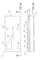
- a radio frequency (RF) microelectromechanical system (MEMS) device 10 according to the present invention is shown.
- the device 10 includes a semiconductor substrate 14, a piezoelectric thin film actuator 16 mounted on the substrate 14, a conducting path electrode 18 driven by the piezoelectric thin film actuator 16, conductive bumps 22 which are connected to an external voltage source (not shown) and provide the voltage necessary for operating the device 10, an RF circuit substrate 24, and RF-in and RF-out path electrodes 32 and 34 mounted on the RF circuit substrate 24 so as to be spaced from the conducting path electrode 18.
- the piezoelectric thin film actuator 16 is fabricated in conjunction with the semiconductor substrate 14 and transferred to the RF circuit substrate 24 using flip chip technology, for example. It is noted that in the illustrated embodiment the bumps shown in the right side of Figs. 1a-1d act as spacers, although the bumps could alternatively form part of another device, if desired.
- the piezoelectric thin film actuator 16 may comprise any suitable material having piezoelectric properties, for example, lead zirconate titanate (PZT).
- PZT lead zirconate titanate
- the PZT thin film actuator 16 includes a pair of electrodes 40 and 42, a piezoelectric layer 44 made of lead zirconate titanate (PZT) disposed between the electrodes 40 and 42, and an elastic layer 50 disposed between the electrode 40 (the upper electrode in Figs. 1 b and 1 c) and the semiconductor substrate 14.
- PZT lead zirconate titanate
- the PZT thin film actuator 16 has a fixed proximal end 54 (the left end in Figs. 1a-1c) adjacent the semiconductor substrate 14 and a free distal end 56 (the right end in Figs. 1a-1c) extending into a trench region 60 of the substrate 14.
- the PZT thin film actuator 16 thus forms a cantilever beam which is moveable within the trench region 60.
- the conducting path electrode 18 is transverse the longitudinal extent of the PZT thin film actuator 16.
- the conducting path electrode is perpendicular to the plane of the page.
- the RF-in and RF-out path electrodes 32 and 34 are transverse the longitudinal extent of the PZT thin film actuator 16, as is shown in Fig. 1d.
- the RF MEMS device 10 in accordance with the invention may be used as a switch with controllable displacement or as a tunable capacitor for varying the capacitance between the electrodes 32 and 34.
- the RF MEMS device 10 changes the distance of the gap between the conducting path electrode 18 and the RF-in and RF-out path electrodes 32 and 34. More particularly, as the voltage source increases and decreases the voltage potential applied to the electrodes 40 and 42, the PZT layer 44 changes its dimension in length, that is, the PZT layer 44 respectively expands and contracts.
- the elastic layer 50 converts the expanding and contracting of the PZT layer 44 into upward and downward movement of the cantilevered or distal end portion 56 of the PZT thin film actuator 16.
- the distal end 56 urges the conducting path electrode 18 closer to or in contact with the RF-in and RF-out path electrodes 32 and 34.
- the distal end 56 urges the conducting path electrode 18 away from the RF-in and RF-out path electrodes 32 and 34.
- the PZT thin film actuator 16 thus actively controls the displacement between the conducting path electrode 18 and the RF-in and RF-out path electrodes 32 and 34.
- the amount of displacement depends on mainly the driving voltage, and the dimensions of the PZT thin film actuator 16, including the dimensions of the PZT layer 44 and the elastic layer 50.
- alternative piezoelectric materials may have different piezoelectric properties than that of PZT and, consequently, alternative embodiments which may such alternative piezoelectric materials may result in different amounts of displacement.
- the RF MEMS device 10 When employed as a switch, the RF MEMS device 10 can close the spacing between the conducting path electrode 18 and the RF-in and RF-out path electrodes 32 and 34, and thus turn on the switch, or open the spacing and thus turn off the switch.
- the RF MEMS device may also employed as a tunable capacitor in which the interelectrode spacing between the conducting path electrode 18 and the RF-in and RF-out path electrodes 32 and 34 is controllably varied by the PZT thin film actuator 16 in order to selectively vary the tuning capacitance therebetween.
- the RF MEMS device 10 with the PZT thin film actuator 16 provides accurate and precise beam displacement control with improved tuning capacitance range, eliminates or substantially reduces static charges collecting on the conducting path electrode 18 and the RF path electrodes 32 and 34, improves tuning reliability, improves switching speed, provides high RF performance, and reduces the required driving voltage. It has been found, for example, that the RF MEMS device 10 operates on one or two volts instead of the approximately 30 to 40 volts used for a conventional RF MEMS switch.
- the RF MEMS device 10 may be used as either a tunable capacitor or an RF MEMS switch. Accordingly, the RF MEMS device 10 is not limited to the on/off nature of electrostatic switches. The switching time of the RF MEMS device 10 is on the order of nanoseconds, which is comparatively better than that of electrothermal RF MEMS switches, which typically have a switching time on the order of milliseconds or microseconds. In addition to the foregoing functional advantages, the RF MEMS device 10 is a relatively simple structure packaged in a relatively small volume.
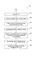
- a method 100 for fabricating a radio frequency (RF) microelectromechanical system (MEMS) device 110 in accordance with the present invention are outlined in the flow chart shown in Fig. 2.
- Figs. 3-10 illustrate various steps of the method 100. It will be appreciated that the method 100 and the RF MEMS device 110 described below are merely exemplary, and that suitable variations in materials, thicknesses, and/or structures may alternatively be used in the method 100 and/or the RF MEMS device 110.
- a multi-layer starting material or stack used to form an RF MEMS device 110 in accordance with the invention is provided.
- the stack includes a semiconductor substrate 112, a protective layer 114 below the substrate 112, and an elastic layer 116 atop the substrate 112.
- a first conductor layer 120, a piezoelectric layer 126, and a second conductor layer 130 are atop the elastic layer 116, in that order.
- the piezoelectric layer 126 is made of lead zirconate titanate (PZT).
- PZT lead zirconate titanate
- alternative suitable piezoelectric materials may be employed as the piezoelectric layer 126.
- a suitable semiconductor substrate 112 material may be silicon (Si), for example.
- the protective layer 114 and elastic layer 116 may be made of silicon nitride (Si 3 N 4 ) or silicon dioxide (SiO 2 ), for example.
- the conductor layers 120 and 130 may be made of platinum (Pt) or other suitable conducting materials.
- an adhesion layer made of, for example, tantalum (Ta), may be disposed between the conductor layer 120 and the elastic layer 116 to improve the adhesion of the conductor layer 120 to the elastic layer 116.
- the PZT layer 126 has a thickness between about 450 nm and about 550 nm (about 4500 and about 5500 Angstroms), and the elastic layer 116 has a thickness between about 0.95 ⁇ m (0.95 microns) and about 1.65 ⁇ m (1.65 microns) for silicon nitride, and between about 1.35 ⁇ m (1.35 microns) and about 1.65 ⁇ m (1.65 microns) for silicon dioxide.
- the top conductor layer 130 is patterned and etched down to the PZT layer 126.
- portions of the conductor layer 130 are removed, thereby leaving an upper conductor pad 144, an upper PZT actuator electrode 146, a conducting path electrode 152, and three spacers or bumps 154, 155 and 156, as shown in Figs. 4a and 4b.
- a mask may be placed on the stack to protect portions of the underlying layers. Formation of the mask may involve depositing a photoresist on the stack, patterning the photoresist, exposing portions of the photoresist such as by selective light exposure, and removing unexposed portions of the photoresist through use of a suitable etching technique, for example, dry etching or wet etching.
- the upper PZT actuator electrode 146 has a length (from left to right in Fig. 4a) between about 300 ⁇ m (300 microns) and about 500 ⁇ m (500 microns), and a width between about 100 ⁇ m (100 microns) and about 150 ⁇ m (150 microns).
- the conducting path electrode 152 has a width (from left to right in Fig. 4a) between about 90 ⁇ m (90 microns) and about 110 ⁇ m (110 microns). The length of the conducting path electrode 152 (from top to bottom in Fig.
- the distance between the distal end of the upper PZT actuator electrode 146 (the rightmost portion of the upper PZT electrode in Fig. 4a) and the conducting path electrode 152 is at least about 100 ⁇ m (100 microns). It will be appreciated that other dimensions may also be suitable, depending on, for example, the desired amount of deflection to be provided by the PZT thin film actuator beam.
- step 160 the PZT layer 126 is patterned and etched down to the bottom conductor layer 120.
- step 160 a new photoresist is deposited and patterned so that portions of the PZT layer 126 are removed, thereby leaving the upper conductor pad 144, the upper PZT actuator electrode 146, the conducting path electrode 152, and the three bumps 154, 155 and 156, as well as a PZT isolation region 170, as shown in Figs. 5a and 5b.
- the PZT isolation region 170 provides high isolation in that it prevents any electric field of the conducting path electrode 152 from extending to the upper PZT actuator electrode 146, or vice versa.
- the isolation region 170 is at least about 100 ⁇ m (100 microns) wide.
- step 180 illustrated in Figs. 6a and 6b, a pattern and etch of the bottom conductor layer 120 is performed to form a lower conductor pad 184 and a lower PZT actuator electrode 186, leaving the structure shown in Figs. 6a and 6b.
- the lower conductor pad 184 is about the same size and shape in plan view as the upper conductor pad 144 (Fig. 6a), and includes a conducting leg or path 188 extending to the lower PZT actuator electrode 186, which is disposed below the PZT layer 126 and the upper PZT actuator electrode 146.
- an isolation layer 192 of silicon nitride or silicon dioxide is deposited on the structure shown in Figs. 7a and 7b, and then patterned for the existing conducting path electrode 152 and three bumps 154, 155 and 156, as well as for the formation of a new bump 204 (to be formed later) in the upper left corner of Fig. 7a, and a bridge post 194 on the upper conductor pad 144 and the upper PZT actuator electrode 146.
- the isolation layer 192 prevents or at least substantially reduces electrical arcing between the upper and lower PZT actuator electrodes 146 and 186.
- step 200 a new photoresist (not shown) is deposited on the structure shown in Figs. 7a and 7b, and then patterned for the existing conducting path electrode 152 and three bumps 154, 155 and 156, the new bump 204 (to be formed later), and a bridge base 208 (also to be formed later) extending from the upper conductor pad 144 to the upper PZT actuator electrode 146.
- step 220 illustrated in Figs. 8a and 8b, a relatively thin layer, for example one ⁇ m (one micron), of TiAu 222 is sputtered on the photoresist layer.
- the photoresist layer controls the deposit of the TiAu to the conducting path electrode 152, the bridge base 208 and the bumps 154, 155, 156 and 204.
- the TiAu base layer 222 improves the adhesion of a conductive layer such as gold (to be deposited later).
- a conductive layer such as gold (to be deposited later).
- any suitable material to improve the adhesion of gold may be used, for example, NiCr/Au, Ta/Au, or Cr/Au.
- the TiAu layer of the conducting path electrode 152 and the bumps 154, 155, 156 and 204 is shown in Figs. 8a and 8b to identify the positions at which the TiAu is sputtered on the underlying material.
- a photoresist 232 (Figs. 9a and 9b) is deposited on the structure shown in Figs. 8a and 8b, and then patterned for the conducting path electrode 152, the bridge base 208 and the bumps 154, 155, 155 and 204.
- a layer of gold 238 is then plated on the exposed portions not covered by the photoresist 232 to form the conducting path electrode 152, a bridge on the bridge base 208, and the bumps 154, 155, 156 and 204.
- the height of the gold bumps 154, 155, 156 and 204 is greater than the height of either the gold bridge 208 or the gold conducting path electrode 152.
- alternative materials to gold may be used, for example, copper.
- a protective layer (not shown) made of, for example, silicon nitride is deposited on the top surface of the stack of Figs. 9a and 9b.
- the protective layer provides a mask or etch protection for the top surface.
- the bottom protective layer 114 is patterned to form a trench region 262.
- the semiconductor layer 112 is etched to form the trench region 262 therein.
- the trench region 262 has a footprint larger than the distal end of the upper and lower PZT actuator electrodes 146 and 186 and the PZT layer 126 disposed therebetween.
- the depth of the trench region 262 is through the thickness of the semiconductor layer 112, that is, to the elastic layer 116.
- the width of the trench region 262 (from top to bottom in Fig. 10a) is greater than the length of the conducting path electrode 152, and the length of the trench region 262 (from left to right in Fig. 10a) is greater than the combined width of the isolation region 170 and the conducting path electrode 152.
- step 270 the top protective layer and the bottom protective layer 114 are etched.
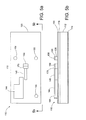
- step 280 illustrated in Figs. 10a-10c, the photoresist layer 232 for gold plating is removed, the TiAu layer that is not the conducting path electrode 152 is removed, the bridge 208 and the bumps 154, 155, 155 and 204 are removed, and the photoresist layer for the TiAu sputtering is removed.
- step 290 also illustrated in Figs. 10a-10c, the elastic layer 116 is removed in the region 292 laterally of, and the region 294 longitudinally beyond, the distal end of the upper and lower PZT actuator electrodes 146 and 186 and the PZT layer 126. Removing the elastic layer 116 in such a manner releases the distal end of the PZT thin film actuator 296 from the semiconductor substrate 112.
- the distal end of the PZT thin film actuator 296 is thus movable up and down (in Fig. 10b) within the trench region 262 and, in this regard, functions in a manner similar to a cantilever beam.
- the desired amount of flexure in the cantilevered end of the PZT thin film actuator 296 may be defined by the length of the trench region 262 and the length of the cantilevered end of the PZT thin film actuator 296.
- the PZT thin film actuator 296 is mounted to an RF circuit substrate 302 using, for example, flip chip technology.
- the RF circuit substrate 302 in one embodiment is made of a suitable RF compatible material, for example, GaAs or ceramics.
- the resulting structure is the RF MEMS device 110.
- the bumps 154, 155, 156 and 204 provide spacing between the PZT thin film actuator 296 and the RF circuit substrate 302. Also, because the height of the bumps 154, 155, 156 and 204 is greater than the height of either the bridge 208 or the conducting path electrode 152, the bridge 208 and conducting path electrode 152 are elevated from the RF circuit substrate 302.
- an RF-in conducting path 304 and an RF-out conducting path 306 are disposed on the RF circuit substrate 302.
- the RF-in and RF-out conducting paths 304 and 306 are spaced apart by a gap L.
- the length of the conducting path electrode 152 is based mainly on the width of the conducting path electrode 152 and the gap L between the RF-in and RF-out conducting paths 304 and 306.
- the gap L between the RF-in and RF-out conducting paths 304 and 306 is about 100 ⁇ m (100 microns) and the length of the conducting path electrode 152 is about 250 ⁇ m (250 microns).
Landscapes
- Engineering & Computer Science (AREA)
- Microelectronics & Electronic Packaging (AREA)
- Power Engineering (AREA)
- Computer Hardware Design (AREA)
- Chemical & Material Sciences (AREA)
- Analytical Chemistry (AREA)
- Manufacturing & Machinery (AREA)
- Micromachines (AREA)
Claims (7)
- Hochfrequenz(HF)-mikroelektromechanisches System (MEMS) Bauteil (10) mit:einem HF-Schaltungssubstrat (24) und einem HF-Leitungspfad (32, 34), der auf dem HF-Schaltungssubstrat (24) angeordnet ist;einem piezoelektrischen Dünnfilm-Aktuator (16) mit einem proximalen Ende, das relativ zu dem HF-Schaltungssubstrat (24) fest ist und ein Ausleger-Ende, das beabstandet von dem HF-Schaltungssubstrat (24) ist;einer leitenden Pfadelektrode (18), die auf dem Ausleger-Ende des piezoelektrischen Dünnfilm-Aktuators (16) angeordnet ist;wobei das Ausleger-Ende des piezoelektrischen Dünnfilm-Aktuators (16) bewegbar ist zwischen einer ersten Position, bei der die leitende Pfadelektrode (18) beabstandet von der HF-Pfadelektrode (32, 34) in einem ersten Abstand ist, und einer zweiten Position, in der die leitende Pfadelektrode (18) beabstandet von der HF-Pfadelektrode (32, 34) in einem zweiten Abstand ist, und wobei der zweite Abstand null oder kleiner als der erste Abstand ist; und
wobei der piezoelektrische Dünnfilm-Aktuator (16) eine erste Elektrode (49), eine zweite Elektrode (42), eine elastische Schicht (50), die auf der zweiten Elektrode (42) aufgebracht ist, eine Isolationsschicht, die auf der elastischen Schicht längs einer Ebene vorgesehen ist, die im Wesentlichen parallel zu der Fläche des HF-Schaltungssubstrats ist, und eine piezoelektrische Schicht (44) aufweist, die zwischen der ersten und der zweiten Elektrode (40, 42) liegt, wobei die Isolationsschicht ein elektrisches Überschlagen zwischen der ersten und der zweiten Elektrode reduziert. - HF-MEMS-Bauteil (10) nach Anspruch 1, wobei der piezoelektrische Dünnfilm-Aktuator (16) eine Schicht aus Blei-Zirkonat-Titanat(PZT)-Material (44) aufweist.
- HF-MEMS-Bauteil (10) nach einem der vorhergehenden Ansprüche, wobei die piezoelektrische Schicht (44) zwischen der ersten und der zweiten Elektrode (40, 42) angeordnet ist, derart, dass, wenn ein Spannungspotential an die erste und die zweite Elektrode (40, 42) angelegt wird, sich die piezoelektrische Schicht (44) in Längsrichtung ausdehnt oder zusammenzieht.
- HF-MEMS-Bauteil (10) nach einem der vorhergehenden Ansprüche, wobei die elastische Schicht (50) auf der zweiten Elektrode (42) angeordnet ist, derart, dass die elastische Schicht (50) die Ausdehnung oder das Zusammenziehen der piezoelektrischen Schicht (44) in Längsrichtung in eine Querrichtung des Ausleger-Endes des piezoelektrischen Dünnfilm-Aktuators (16) wandelt.
- HF-MEMS-Bauteil (10) nach einem der vorhergehenden Ansprüche, wobei die erste Elektrode (40) und die zweite Elektrode (42) eine Schicht aus Platin aufweisen.
- Verfahren zur Herstellung eines HF-MEMS-Bauteils (110), mit:Bereitstellen eines HF-Schaltungssubstrats (302) mit einem HF-leitenden Pfad (304, 306), der auf dem HF-Schaltungssubstrat (302) angeordnet ist;Herstellen eines piezoelektrischen Dünnfilm-Aktuators (296) mit einem proximalen Ende und einem Ausleger-Ende;Bereitstellen eines Mehrschichtmaterials mit einer Schutzschicht (114), einer Halbleiterschicht (112), einer elastischen Schicht (116), einer ersten Leiterschicht (120), einer piezoelektrischen Schicht (126) und einer zweiten Leiterschicht (130), wobei die piezoelektrische Schicht (126) zwischen der ersten und der zweiten Leiterschicht (120, 130) angeordnet ist;Strukturieren und Ätzen der ersten Leiterschicht (120), der piezoelektrischen Schicht (126) und der zweiten Leiterschicht (130), um eine erste Elektrode (146), eine piezoelektrische Schicht (126) und eine zweite Elektrode (186) auszubilden;Bereitstellen einer leitenden Pfadelektrode (152) auf dem Ausleger-Ende des piezoelektrischen Dünnfilm-Aktuators (296) mit Strukturierung und Ätzen der ersten Leiterschicht (120), der piezoelektrischen Schicht (126) und der zweiten Leiterschicht (130), um die leitende Pfadelektrode (52) auszubilden, wobei die leitende Pfadelektrode (152) beabstandet von entweder der ersten oder der zweiten Elektrode (146, 186) durch einen Isolationsbereich (170) ist, der durch die piezoelektrische Schicht (126) gebildet wird; undZusammensetzen des piezoelektrischen Dünnfilm-Aktuators (296) zu dem HF-Schaltungssubstrat (302), so dass das proximale Ende relativ zu dem HF-Schaltungssubstrat (302) fest ist und das Ausleger-Ende beabstandet von dem HF-Schaltungssubstrat (302) ist, und so dass das Ausleger-Ende des piezoelektrischen Dünnfilm-Aktuators (296) zwischen einer ersten Position, in der die leitende Pfadelektrode (152) beabstandet von der HF-Pfadelektrode (304, 306) ist, und einer zweiten Position bewegbar ist, in der die leitende Pfadelektrode (152) von der HF-Pfadelektrode (304, 306) in einem zweiten Abstand beabstandet ist, und wobei der zweite Abstand null oder kleiner als der erste Abstand ist.
- Verfahren nach Anspruch 6, wobei der Schritt des Ausbildens des piezoelektrischen Dünnfilm-Aktuators (296) das Ausbilden einer Schicht aus Blei-Zirkonat-Titanat(PZT)-Material umfasst.
Applications Claiming Priority (3)
| Application Number | Priority Date | Filing Date | Title |
|---|---|---|---|
| US10/294,413 US7132723B2 (en) | 2002-11-14 | 2002-11-14 | Micro electro-mechanical system device with piezoelectric thin film actuator |
| US294413 | 2002-11-14 | ||
| PCT/US2003/036595 WO2004047190A2 (en) | 2002-11-14 | 2003-11-14 | Micro electro-mechanical system device with piezoelectric thin film actuator |
Publications (2)
| Publication Number | Publication Date |
|---|---|
| EP1560787A2 EP1560787A2 (de) | 2005-08-10 |
| EP1560787B1 true EP1560787B1 (de) | 2007-04-04 |
Family
ID=32296977
Family Applications (1)
| Application Number | Title | Priority Date | Filing Date |
|---|---|---|---|
| EP03786748A Expired - Lifetime EP1560787B1 (de) | 2002-11-14 | 2003-11-14 | Mikroelektromechanisches bauteil mit piezoelektrischem dünnfilmaktuator |
Country Status (9)
| Country | Link |
|---|---|
| US (1) | US7132723B2 (de) |
| EP (1) | EP1560787B1 (de) |
| KR (1) | KR20050086629A (de) |
| AU (1) | AU2003295553B2 (de) |
| DE (1) | DE60313018T2 (de) |
| DK (1) | DK1560787T3 (de) |
| ES (1) | ES2282713T3 (de) |
| NO (1) | NO332052B1 (de) |
| WO (1) | WO2004047190A2 (de) |
Families Citing this family (30)
| Publication number | Priority date | Publication date | Assignee | Title |
|---|---|---|---|---|
| US7446217B2 (en) * | 2002-11-14 | 2008-11-04 | Advanced Technology Materials, Inc. | Composition and method for low temperature deposition of silicon-containing films |
| US7531679B2 (en) * | 2002-11-14 | 2009-05-12 | Advanced Technology Materials, Inc. | Composition and method for low temperature deposition of silicon-containing films such as films including silicon nitride, silicon dioxide and/or silicon-oxynitride |
| GB0300664D0 (en) * | 2003-01-11 | 2003-02-12 | Rolls Royce Plc | Sensing film material |
| US7601860B2 (en) | 2003-10-10 | 2009-10-13 | Advanced Technology Materials, Inc. | Composition and method for low temperature chemical vapor deposition of silicon-containing films including silicon carbonitride and silicon oxycarbonitride films |
| US7579496B2 (en) | 2003-10-10 | 2009-08-25 | Advanced Technology Materials, Inc. | Monosilane or disilane derivatives and method for low temperature deposition of silicon-containing films using the same |
| EP1548748A1 (de) * | 2003-12-17 | 2005-06-29 | Interuniversitaire Microelectronica Centrum vzw ( IMEC) | Verfahren zur Herstellung von Sonden für Atomkraftmikroskopie |
| JP2007515306A (ja) * | 2003-12-22 | 2007-06-14 | コーニンクレッカ フィリップス エレクトロニクス エヌ ヴィ | 電子装置 |
| DE602005005189T2 (de) * | 2004-05-06 | 2009-03-19 | Nxp B.V. | Elektronische einrichtung |
| JP4744849B2 (ja) | 2004-11-11 | 2011-08-10 | 株式会社東芝 | 半導体装置 |
| US7198975B2 (en) * | 2004-12-21 | 2007-04-03 | Taiwan Semiconductor Manufacturing Company | Semiconductor methods and structures |
| KR100668617B1 (ko) * | 2005-01-06 | 2007-01-16 | 엘지전자 주식회사 | 알에프 파워 검출장치 및 그 제조방법 |
| US7098576B2 (en) * | 2005-01-10 | 2006-08-29 | Raytheon Company | Micro-electrical-mechanical device and method of making same |
| US7623007B2 (en) * | 2005-10-19 | 2009-11-24 | Panasonic Corporation | Device including piezoelectric thin film and a support having a vertical cross-section with a curvature |
| KR101092536B1 (ko) * | 2005-11-30 | 2011-12-13 | 삼성전자주식회사 | 압전형 rf 멤스 소자 및 그 제조방법 |
| US7556978B2 (en) * | 2006-02-28 | 2009-07-07 | Freescale Semiconductor, Inc. | Piezoelectric MEMS switches and methods of making |
| JP4316590B2 (ja) | 2006-06-23 | 2009-08-19 | 株式会社東芝 | 圧電駆動型memsアクチュエータ |
| US7830066B2 (en) * | 2007-07-26 | 2010-11-09 | Freescale Semiconductor, Inc. | Micromechanical device with piezoelectric and electrostatic actuation and method therefor |
| JP5079456B2 (ja) * | 2007-11-06 | 2012-11-21 | 新光電気工業株式会社 | 半導体装置及びその製造方法 |
| WO2013177326A1 (en) | 2012-05-25 | 2013-11-28 | Advanced Technology Materials, Inc. | Silicon precursors for low temperature ald of silicon-based thin-films |
| US10726231B2 (en) | 2012-11-28 | 2020-07-28 | Invensense, Inc. | Integrated piezoelectric microelectromechanical ultrasound transducer (PMUT) on integrated circuit (IC) for fingerprint sensing |
| US9114977B2 (en) * | 2012-11-28 | 2015-08-25 | Invensense, Inc. | MEMS device and process for RF and low resistance applications |
| US10497747B2 (en) | 2012-11-28 | 2019-12-03 | Invensense, Inc. | Integrated piezoelectric microelectromechanical ultrasound transducer (PMUT) on integrated circuit (IC) for fingerprint sensing |
| US9618405B2 (en) | 2014-08-06 | 2017-04-11 | Invensense, Inc. | Piezoelectric acoustic resonator based sensor |
| US9511994B2 (en) | 2012-11-28 | 2016-12-06 | Invensense, Inc. | Aluminum nitride (AlN) devices with infrared absorption structural layer |
| TWI621242B (zh) * | 2013-09-19 | 2018-04-11 | 伊凡聖斯股份有限公司 | 具有紅外線吸收結構層的氮化鋁(ain)裝置 |
| JP6601174B2 (ja) * | 2015-11-13 | 2019-11-06 | セイコーエプソン株式会社 | 圧電アクチュエーター、積層アクチュエーター、圧電モーター、ロボット、ハンド及び送液ポンプ |
| CN105449327B (zh) * | 2015-12-23 | 2018-01-16 | 西安电子科技大学 | 基于机电耦合的分布式mems移相器电容桥高度公差的确定方法 |
| CN105489978B (zh) * | 2016-01-21 | 2018-01-16 | 西安电子科技大学 | 基于相移量机电耦合的分布式mems移相器工作电压的调整方法 |
| US10291283B2 (en) * | 2016-04-01 | 2019-05-14 | Intel Corporation | Tunable radio frequency systems using piezoelectric package-integrated switching devices |
| US11489461B2 (en) * | 2020-05-26 | 2022-11-01 | Microsoft Technology Licensing, Llc | Thin film actuator having transversely oriented structural stiffeners to increase actuator stroke |
Family Cites Families (9)
| Publication number | Priority date | Publication date | Assignee | Title |
|---|---|---|---|---|
| US2708244A (en) * | 1954-03-24 | 1955-05-10 | Jaffe Bernard | Piezoelectric transducers using lead titanate and lead zirconate |
| US4342936A (en) * | 1980-12-19 | 1982-08-03 | Eastman Kodak Company | High deflection bandwidth product polymeric piezoelectric flexure mode device and method of making same |
| US4868448A (en) * | 1986-09-24 | 1989-09-19 | General Electric Company | Piezoelectric relay switching matrix |
| US5536963A (en) * | 1994-05-11 | 1996-07-16 | Regents Of The University Of Minnesota | Microdevice with ferroelectric for sensing or applying a force |
| GB2353410B (en) * | 1999-08-18 | 2002-04-17 | Marconi Electronic Syst Ltd | Electrical switches |
| US6504118B2 (en) * | 2000-10-27 | 2003-01-07 | Daniel J Hyman | Microfabricated double-throw relay with multimorph actuator and electrostatic latch mechanism |
| JP2002170470A (ja) * | 2000-11-28 | 2002-06-14 | Matsushita Electric Works Ltd | 半導体マイクロリレー及びその製造方法 |
| US20020096421A1 (en) | 2000-11-29 | 2002-07-25 | Cohn Michael B. | MEMS device with integral packaging |
| US7098577B2 (en) * | 2002-10-21 | 2006-08-29 | Hrl Laboratories, Llc | Piezoelectric switch for tunable electronic components |
-
2002
- 2002-11-14 US US10/294,413 patent/US7132723B2/en not_active Expired - Lifetime
-
2003
- 2003-11-14 ES ES03786748T patent/ES2282713T3/es not_active Expired - Lifetime
- 2003-11-14 AU AU2003295553A patent/AU2003295553B2/en not_active Ceased
- 2003-11-14 DK DK03786748T patent/DK1560787T3/da active
- 2003-11-14 EP EP03786748A patent/EP1560787B1/de not_active Expired - Lifetime
- 2003-11-14 KR KR1020057008642A patent/KR20050086629A/ko not_active Ceased
- 2003-11-14 DE DE60313018T patent/DE60313018T2/de not_active Expired - Lifetime
- 2003-11-14 WO PCT/US2003/036595 patent/WO2004047190A2/en not_active Ceased
-
2005
- 2005-06-03 NO NO20052671A patent/NO332052B1/no not_active IP Right Cessation
Also Published As
| Publication number | Publication date |
|---|---|
| US7132723B2 (en) | 2006-11-07 |
| ES2282713T3 (es) | 2007-10-16 |
| WO2004047190A3 (en) | 2004-10-28 |
| US20040094815A1 (en) | 2004-05-20 |
| EP1560787A2 (de) | 2005-08-10 |
| AU2003295553A1 (en) | 2004-06-15 |
| KR20050086629A (ko) | 2005-08-30 |
| DE60313018T2 (de) | 2007-12-13 |
| NO332052B1 (no) | 2012-06-11 |
| DK1560787T3 (da) | 2007-08-20 |
| NO20052671L (no) | 2005-06-03 |
| WO2004047190A2 (en) | 2004-06-03 |
| AU2003295553B2 (en) | 2007-05-31 |
| DE60313018D1 (de) | 2007-05-16 |
Similar Documents
| Publication | Publication Date | Title |
|---|---|---|
| EP1560787B1 (de) | Mikroelektromechanisches bauteil mit piezoelektrischem dünnfilmaktuator | |
| US6232847B1 (en) | Trimmable singleband and tunable multiband integrated oscillator using micro-electromechanical system (MEMS) technology | |
| US5880921A (en) | Monolithically integrated switched capacitor bank using micro electro mechanical system (MEMS) technology | |
| US6215644B1 (en) | High frequency tunable capacitors | |
| US6307452B1 (en) | Folded spring based micro electromechanical (MEM) RF switch | |
| US7053737B2 (en) | Stress bimorph MEMS switches and methods of making same | |
| RU2433499C2 (ru) | Радиочастотный микроэлектромеханический переключатель (рч мэмс-переключатель) с гибкой и свободной мембраной переключателя | |
| US6377438B1 (en) | Hybrid microelectromechanical system tunable capacitor and associated fabrication methods | |
| US7256670B2 (en) | Diaphragm activated micro-electromechanical switch | |
| EP1343189B1 (de) | HF mikroelektromechanische Vorrichtung | |
| WO2002096796A2 (en) | Membrane for micro-electro-mechanical switch, and methods of making and using it | |
| US7755459B2 (en) | Micro-switching device and method of manufacturing the same | |
| US20100001355A1 (en) | RF MEMS Switch | |
| JP2007535797A (ja) | マイクロマシン技術(mems)スイッチ用のビーム | |
| US20140183014A1 (en) | Electric equipment having movable portion, and its manufacture | |
| JP4504237B2 (ja) | ウエットエッチング方法、マイクロ可動素子製造方法、およびマイクロ可動素子 | |
| JP4820816B2 (ja) | 微小電気機械素子およびこれを用いた電気機械スイッチ | |
| US7960900B2 (en) | Assembly of a microswitch and of an acoustic resonator | |
| US20060091983A1 (en) | Electrostatic microswitch for low-voltage-actuation component | |
| US20040166602A1 (en) | Electro-thermally actuated lateral-contact microrelay and associated manufacturing process | |
| JP4628275B2 (ja) | マイクロスイッチング素子およびマイクロスイッチング素子製造方法 | |
| JP4932506B2 (ja) | マイクロスイッチング素子 | |
| KR100773005B1 (ko) | 격벽 작동형 마이크로 전기 기계 스위치 | |
| JP2007026726A (ja) | Memsスイッチ |
Legal Events
| Date | Code | Title | Description |
|---|---|---|---|
| PUAI | Public reference made under article 153(3) epc to a published international application that has entered the european phase |
Free format text: ORIGINAL CODE: 0009012 |
|
| 17P | Request for examination filed |
Effective date: 20041210 |
|
| AK | Designated contracting states |
Kind code of ref document: A2 Designated state(s): AT BE BG CH CY CZ DE DK EE ES FI FR GB GR HU IE IT LI LU MC NL PT RO SE SI SK TR |
|
| RBV | Designated contracting states (corrected) |
Designated state(s): DE DK ES FR NL SE |
|
| RIC1 | Information provided on ipc code assigned before grant |
Ipc: H01L 41/24 20060101ALI20060816BHEP Ipc: H01G 5/16 20060101ALI20060816BHEP Ipc: H01L 41/09 20060101ALI20060816BHEP Ipc: H01H 57/00 20060101ALI20060816BHEP Ipc: B81B 3/00 20060101AFI20060816BHEP |
|
| GRAP | Despatch of communication of intention to grant a patent |
Free format text: ORIGINAL CODE: EPIDOSNIGR1 |
|
| RIN1 | Information on inventor provided before grant (corrected) |
Inventor name: PARK, JOON,C/O RAYTHEON COMPANY Inventor name: ALLISON, ROBERT, C.,C/O RAYTHEON COMPANY Inventor name: NAKAHIRA, RON, K.,C/O RAYTHEON COMPANY |
|
| GRAS | Grant fee paid |
Free format text: ORIGINAL CODE: EPIDOSNIGR3 |
|
| GRAA | (expected) grant |
Free format text: ORIGINAL CODE: 0009210 |
|
| AK | Designated contracting states |
Kind code of ref document: B1 Designated state(s): DE DK ES FR NL SE |
|
| REF | Corresponds to: |
Ref document number: 60313018 Country of ref document: DE Date of ref document: 20070516 Kind code of ref document: P |
|
| REG | Reference to a national code |
Ref country code: SE Ref legal event code: TRGR |
|
| REG | Reference to a national code |
Ref country code: DK Ref legal event code: T3 |
|
| ET | Fr: translation filed | ||
| REG | Reference to a national code |
Ref country code: ES Ref legal event code: FG2A Ref document number: 2282713 Country of ref document: ES Kind code of ref document: T3 |
|
| PLBE | No opposition filed within time limit |
Free format text: ORIGINAL CODE: 0009261 |
|
| STAA | Information on the status of an ep patent application or granted ep patent |
Free format text: STATUS: NO OPPOSITION FILED WITHIN TIME LIMIT |
|
| 26N | No opposition filed |
Effective date: 20080107 |
|
| REG | Reference to a national code |
Ref country code: FR Ref legal event code: PLFP Year of fee payment: 13 |
|
| REG | Reference to a national code |
Ref country code: FR Ref legal event code: PLFP Year of fee payment: 14 |
|
| REG | Reference to a national code |
Ref country code: FR Ref legal event code: PLFP Year of fee payment: 15 |
|
| REG | Reference to a national code |
Ref country code: FR Ref legal event code: PLFP Year of fee payment: 16 |
|
| PGFP | Annual fee paid to national office [announced via postgrant information from national office to epo] |
Ref country code: NL Payment date: 20181114 Year of fee payment: 16 |
|
| PGFP | Annual fee paid to national office [announced via postgrant information from national office to epo] |
Ref country code: DK Payment date: 20181109 Year of fee payment: 16 |
|
| PGFP | Annual fee paid to national office [announced via postgrant information from national office to epo] |
Ref country code: GB Payment date: 20181130 Year of fee payment: 6 |
|
| REG | Reference to a national code |
Ref country code: DK Ref legal event code: EBP Effective date: 20191130 |
|
| REG | Reference to a national code |
Ref country code: NL Ref legal event code: MM Effective date: 20191201 |
|
| PG25 | Lapsed in a contracting state [announced via postgrant information from national office to epo] |
Ref country code: NL Free format text: LAPSE BECAUSE OF NON-PAYMENT OF DUE FEES Effective date: 20191201 |
|
| PG25 | Lapsed in a contracting state [announced via postgrant information from national office to epo] |
Ref country code: DK Free format text: LAPSE BECAUSE OF NON-PAYMENT OF DUE FEES Effective date: 20191130 |
|
| REG | Reference to a national code |
Ref country code: ES Ref legal event code: FD2A Effective date: 20210526 |
|
| PG25 | Lapsed in a contracting state [announced via postgrant information from national office to epo] |
Ref country code: ES Free format text: LAPSE BECAUSE OF NON-PAYMENT OF DUE FEES Effective date: 20191115 |
|
| PGFP | Annual fee paid to national office [announced via postgrant information from national office to epo] |
Ref country code: FR Payment date: 20221021 Year of fee payment: 20 |
|
| PGFP | Annual fee paid to national office [announced via postgrant information from national office to epo] |
Ref country code: SE Payment date: 20221024 Year of fee payment: 20 Ref country code: DE Payment date: 20220616 Year of fee payment: 20 |
|
| REG | Reference to a national code |
Ref country code: DE Ref legal event code: R071 Ref document number: 60313018 Country of ref document: DE |
|
| REG | Reference to a national code |
Ref country code: SE Ref legal event code: EUG |