EP1560671B1 - Pignon de direction - Google Patents
Pignon de direction Download PDFInfo
- Publication number
- EP1560671B1 EP1560671B1 EP03767794A EP03767794A EP1560671B1 EP 1560671 B1 EP1560671 B1 EP 1560671B1 EP 03767794 A EP03767794 A EP 03767794A EP 03767794 A EP03767794 A EP 03767794A EP 1560671 B1 EP1560671 B1 EP 1560671B1
- Authority
- EP
- European Patent Office
- Prior art keywords
- section
- angle
- cone
- steering
- axle
- Prior art date
- Legal status (The legal status is an assumption and is not a legal conclusion. Google has not performed a legal analysis and makes no representation as to the accuracy of the status listed.)
- Expired - Lifetime
Links
- 230000007704 transition Effects 0.000 claims abstract description 30
- 230000008878 coupling Effects 0.000 claims abstract description 4
- 238000010168 coupling process Methods 0.000 claims abstract description 4
- 238000005859 coupling reaction Methods 0.000 claims abstract description 4
- 230000007423 decrease Effects 0.000 claims description 4
- 238000005242 forging Methods 0.000 description 3
- 238000003825 pressing Methods 0.000 description 2
- 238000003860 storage Methods 0.000 description 2
- 230000015572 biosynthetic process Effects 0.000 description 1
- 238000000641 cold extrusion Methods 0.000 description 1
- 230000003247 decreasing effect Effects 0.000 description 1
- 230000001419 dependent effect Effects 0.000 description 1
- 238000003754 machining Methods 0.000 description 1
- 238000000034 method Methods 0.000 description 1
- 238000013517 stratification Methods 0.000 description 1
Images


Classifications
-
- F—MECHANICAL ENGINEERING; LIGHTING; HEATING; WEAPONS; BLASTING
- F16—ENGINEERING ELEMENTS AND UNITS; GENERAL MEASURES FOR PRODUCING AND MAINTAINING EFFECTIVE FUNCTIONING OF MACHINES OR INSTALLATIONS; THERMAL INSULATION IN GENERAL
- F16H—GEARING
- F16H55/00—Elements with teeth or friction surfaces for conveying motion; Worms, pulleys or sheaves for gearing mechanisms
- F16H55/02—Toothed members; Worms
- F16H55/17—Toothed wheels
-
- B—PERFORMING OPERATIONS; TRANSPORTING
- B21—MECHANICAL METAL-WORKING WITHOUT ESSENTIALLY REMOVING MATERIAL; PUNCHING METAL
- B21K—MAKING FORGED OR PRESSED METAL PRODUCTS, e.g. HORSE-SHOES, RIVETS, BOLTS OR WHEELS
- B21K1/00—Making machine elements
- B21K1/28—Making machine elements wheels; discs
- B21K1/30—Making machine elements wheels; discs with gear-teeth
-
- B—PERFORMING OPERATIONS; TRANSPORTING
- B62—LAND VEHICLES FOR TRAVELLING OTHERWISE THAN ON RAILS
- B62D—MOTOR VEHICLES; TRAILERS
- B62D3/00—Steering gears
- B62D3/02—Steering gears mechanical
- B62D3/12—Steering gears mechanical of rack-and-pinion type
-
- Y—GENERAL TAGGING OF NEW TECHNOLOGICAL DEVELOPMENTS; GENERAL TAGGING OF CROSS-SECTIONAL TECHNOLOGIES SPANNING OVER SEVERAL SECTIONS OF THE IPC; TECHNICAL SUBJECTS COVERED BY FORMER USPC CROSS-REFERENCE ART COLLECTIONS [XRACs] AND DIGESTS
- Y10—TECHNICAL SUBJECTS COVERED BY FORMER USPC
- Y10T—TECHNICAL SUBJECTS COVERED BY FORMER US CLASSIFICATION
- Y10T74/00—Machine element or mechanism
- Y10T74/19—Gearing
- Y10T74/19949—Teeth
- Y10T74/19963—Spur
- Y10T74/19972—Spur form
Definitions
- the invention relates to a cold or hot forming toothed ready-made steering pinion as one-piece Coupling connection between steering shaft and Rack of a steering device on a motor vehicle, wherein the steering pinion a cylindrical toothed portion with a helical gearing on his Outside and an adjoining thereto having cylindrical axis portion whose diameter is greater than that of the gear section and the end portion of a driving recess for the Includes connection of the steering shaft, and where a transition area between the root of helical gearing and the axle section is provided.
- the present invention has the object based, such a design of the steering pinion to provide that the corresponding cavity of the when forming dies used the flow of material in two opposite directions favors, namely on the one hand to fill the cylindrical toothing section and on the other hand, the subsequent thereto Axle section of the steering pinion.
- the transition region between the root circle of the helical gear and the larger diameter shaft portion comprises at least two cone sections, namely a radially outer cone portion with a first cone angle ⁇ 1 (jam angle) extending between the tip circle diameter at the tooth end of the helical toothing and extends the axle portion, and a radially inner cone portion with a second cone angle ⁇ 2 (entry angle) extending between the tip circle diameter at the tooth end and the root circle of the helical toothing that the stowage angle ⁇ 1 is greater than the entry angle ⁇ 2 and that the transition region describes at least one rounding section with a first radius R1, which leads from the outer cone section to the cylindrical lateral surface of the axle section.
- Such a design of the steering pinion is achieved in its forming that the flow resistance ⁇ 1 and inlet angle ⁇ 2 can be controlled by a suitable choice of stowage angle such that a complete filling of the Gesenkhohlraums is ensured.
- the resistance during pressing can be adjusted so that the material of the blank flows in a coordinated manner in both opposite directions. It is preferable to strive that upon complete filling of the axle section, the elongated threads of the helical gear in the region of the toothing section are also completely filled.
- An important finding in the context of the present invention is that the material is pressed in the opposite direction by a suitable choice of the entry resistance in the toothed section, generating a sufficient back pressure. As a result, a perfect filling of the axle section can be achieved even with relatively large dimensioned driving recess.
- the storage angle ⁇ 1 depending on the cross section of the driving recess is determined such that it increases or decreases according to the dimension of the cross section of the driving recess, based on the outer diameter of the axle section.
- the cross-sectional ratio between driving recess and axle section increases, it is preferable to select a correspondingly larger stowage angle ⁇ 1 .
- the invention provides that this is dependent on the spiral angle ⁇ of the helical toothing determined such that it to a change in angle of the spiral angle ⁇ counter-increasing or decreasing.
- the influence of the helical angle ⁇ is compensated for the flow resistance, so that there is the possibility to coordinate the flow of material in the direction of toothing and opposite in the direction of the axis section.
- a rounding section with a second radius R2 is preferably provided, which forms the transition between the outer and the inner cone section.
- a further rounding section can be provided with a third radius R3, which leads from the inner cone section to the root circle of the helical toothing. In this way, virtually creates a transition region with a turning point in height of the tip diameter at the tooth end, provided that the inlet angle ⁇ 2 is smaller than the storage angle ⁇ 1 .
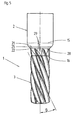
- Fig. 1 shows an inventive steering pinion 1 in three-dimensional representation. It has a cylindrical Achsabêt 2 and in the same axis Extension of a likewise cylindrical toothed section 3 with a helical or helical toothing, which extends over its entire length.
- the steering pinion 1 is a rack 4 shown in dashed lines assigned to a steering in a motor vehicle, which has a toothed section 5. At a finished steering engages the helical gearing of the steering pinion 1 in the rack 4 and moves them according to the steering angle, which over the steering column of the motor vehicle to a dashed line shown Steering shaft 6 is transmitted.
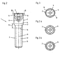
- the steering shaft 6 has two at its the steering pinion 1 end facing two opposing flats 7, which Wrench surfaces for the clutch with a in Fig. 1st not visible, but in Figures 2 and 3 of the Drawing shown driving recess 9 in which the Steering shaft facing end of the Achsabitess 2 form.
- the steering shaft 6 has at its coupling end a cylindrical spigot 8, in a corresponding Bore 11 (Fig. 2) in the center of the driving recess 9 ( Figure 2).
- the bore 11 can either by forming or subsequent machining be introduced.
- Fig. 3 corresponds to the sectional plane III - III in Fig. 2nd
- FIGS. 3a, 3b show alternatives to FIG. 3, namely according to Fig. 3a a driving recess, whose Key surfaces formed by a hexagonal profile are and according to FIG. 3b a driving recess, which is formed in the manner of an internal spline.
- Fig. 4 schematically illustrates the inventive Approach. It is a representation of the Steering pinion 1 in the transition region 14 in half Section through the longitudinal axis 19.
- the height of the upper line 15 results through the transition between the radius R1 to the cylindrical Sheath of the shaft section 2.
- the lower limit line 16 results from the transition of the radius R3 the bland Vietnamese malmesser 12.
- Plotted is also corresponding to the tip diameter of the toothing Outline 13 of the toothing section 3.
- four more horizontal Lines 21 to 24 will be explained, which are parallel to the boundary lines 15, 16 of the transition area 14, namely within the same run. They provide a detailed description of the transition area, as defined in claim 1 is.
- Line 21 generates with the contour of the transition region a point of intersection 31 in the transition between the curvature.
- Radius R1 and a radially outer cone portion 25, the cone angle is referred to as stowage angle ⁇ 1 .
- the height of the line 22 results from the point of intersection 32 between the inner end of the outer cone portion 25 and the radius R2, which extends through the outline 13 corresponding to the tip diameter of the toothed portion 3 and forms the transition to a radially inner cone portion 26.
- the point of intersection 33 between the radius R2 and the radially inner cone portion 26 defines the height of the line 23.
- the radially inner end of the inner cone portion 26 is marked by the point of intersection 34 with the line 24.
- a transition region 14 consisting of two cone sections 25, 26 and three radii R1, R2, R3 is defined. It is essential only the radius R1, which bridges the large diameter jump between the axle section 2 and toothing section 3. It is quite conceivable that the radii R2 and R3 are dispensed with, in particular when stowage angle ⁇ 1 and entry angle ⁇ 2 do not differ greatly from one another. In this case, the intersection points 32 and 33 move over one another so that they come to lie on the outline 13 corresponding to the tip circle 13 of the toothing and the point of intersection 34 moves over the point of intersection 35 on the adjacent boundary line 16 of the transition region 14th
- the outer cone section 25 means an increased entry resistance, the greater the stowage angle ⁇ 1 is selected. Only when this resistance range is overcome, the smaller inlet angle ⁇ 2 determines the further flow resistance of the material during filling of the spiral toothing forming mold. The smaller the lead-in angle ⁇ 2 is chosen, the faster the toothed section 3 fills. However, it must be noted here that the lead-in angle ⁇ 2 depends on the spiral angle ⁇ of the helical toothing (see FIG. 5), in such a way that the lead-in angle ⁇ 2 increases or decreases counter to an angular change of the spiral angle ⁇ . In this case, an increase in the spiral angle ⁇ is absorbed by a smaller inlet angle ⁇ 2 , whereby the inlet resistance is reduced, and vice versa.
- Fig. 5 shows an enlarged view of the spiral toothing in the area of the gearing section 3 with indication of the spiral angle ⁇ .
- Lines 15 and 16 limit the transition area 14 acc. to the Figs. 2 and 4 explained definition.
- Line 28 denotes the the axle section 2 facing the end of the helical toothing. Between the lines 21 and 22 extends radially outer cone section 25.
- the formation of the hollow shape of the die in the input region of the toothed section 3 corresponds to the approximately triangular surface 29, which corresponds to the radially inner cone section 26, whose inclination is determined by the inlet angle ⁇ 2 .
- This triangular shape 29 forms the transition of the inlet region to the actual spiral toothing.
Landscapes
- Engineering & Computer Science (AREA)
- Mechanical Engineering (AREA)
- General Engineering & Computer Science (AREA)
- Chemical & Material Sciences (AREA)
- Combustion & Propulsion (AREA)
- Transportation (AREA)
- Gears, Cams (AREA)
- Transmission Devices (AREA)
- Forging (AREA)
- Power Steering Mechanism (AREA)
- Steering Controls (AREA)
- Control And Other Processes For Unpacking Of Materials (AREA)
- Saccharide Compounds (AREA)
- Medicines Containing Plant Substances (AREA)
- Retarders (AREA)
Claims (5)
- Pignon de direction (1) réalisé par formage à froid ou à chaud, de manière à être prêt à s'engrener, servant de liaison d'accouplement entre l'arbre de direction (6) et la crémaillère (4) d'un dispositif de direction d'un véhicule automobile, le pignon de direction (1) présentant un segment denté (3) cylindrique, avec une denture hélicoïdale sur sa face extérieure, ainsi qu'un segment formant axe (2) cylindrique qui fait suite de façon coaxiale au segment denté et dont le diamètre est supérieur à celui du segment denté (3) et dont la portion d'extrémité comporte une cavité d'entraínement (9) pour le raccordement de l'arbre de direction (6), et une zone de transition (14) étant prévue entre le cercle de pied (12) de la denture hélicoïdale et le segment formant axe (2), caractérisé en ce que la zone de transition (14) comprend au moins deux portions coniques, à savoir une portion conique (25) radialement extérieure, avec un premier angle de cône (α1), située entre le diamètre de tête (13) côté extrémité de denture de la denture hélicoïdale et le segment formant axe (2), et une portion conique (26) radialement intérieure, avec un deuxième angle de cône (α2), située entre le diamètre de tête (13) côté extrémité de denture et le cercle de pied (12) de la denture hélicoïdale, en ce que le premier angle de cône (α1) est supérieur au deuxième angle de cône (α2) et en ce que la zone de transition (14) définit au moins une portion arrondie avec un premier rayon (R1), qui forme la transition entre la portion conique extérieure (25) et la surface enveloppe cylindrique du segment formant axe (2)
- Pignon de direction selon la revendication 1, caractérisé en ce que le premier angle de cône (α1) est déterminé en fonction de la section creuse de la cavité d'entraínement (9), de manière telle que, en fonction de la dimension de la section, ledit angle (α1) augmente ou diminue dans le même sens, rapporté au diamètre extérieur du segment formant axe (2).
- Pignon de direction selon la revendication 1, caractérisé en ce que le deuxième angle de cône (α2) est déterminé en fonction de l'angle d'hélice (β) de la denture hélicoïdale, de manière telle qu'il (α2) augmente ou diminue dans le sens opposé à une variation de l'angle d'hélice.
- Pignon de direction selon la revendication 1, caractérisé en ce que la zone de transition (14) définit une portion arrondie avec un deuxième rayon (R2), qui forme la transition entre la portion conique extérieure (25) et la portion conique intérieure (26).
- Pignon de direction selon la revendication 1, caractérisé en ce que la zone de transition (14) définit une portion arrondie avec un troisième rayon (R3), qui forme la transition entre la portion conique intérieure (26) et le cercle de pied (12) de la denture hélicoïdale.
Applications Claiming Priority (3)
| Application Number | Priority Date | Filing Date | Title |
|---|---|---|---|
| DE10260426A DE10260426B3 (de) | 2002-12-21 | 2002-12-21 | Lenkritzel |
| DE10260426 | 2002-12-21 | ||
| PCT/EP2003/014131 WO2004056504A1 (fr) | 2002-12-21 | 2003-12-12 | Pignon de direction |
Publications (2)
| Publication Number | Publication Date |
|---|---|
| EP1560671A1 EP1560671A1 (fr) | 2005-08-10 |
| EP1560671B1 true EP1560671B1 (fr) | 2005-08-17 |
Family
ID=32336561
Family Applications (1)
| Application Number | Title | Priority Date | Filing Date |
|---|---|---|---|
| EP03767794A Expired - Lifetime EP1560671B1 (fr) | 2002-12-21 | 2003-12-12 | Pignon de direction |
Country Status (12)
| Country | Link |
|---|---|
| US (1) | US20050061101A1 (fr) |
| EP (1) | EP1560671B1 (fr) |
| JP (1) | JP4527545B2 (fr) |
| CN (1) | CN1311932C (fr) |
| AT (1) | ATE302076T1 (fr) |
| BR (1) | BR0307012A (fr) |
| CA (1) | CA2510195A1 (fr) |
| DE (2) | DE10260426B3 (fr) |
| ES (1) | ES2247559T3 (fr) |
| MX (1) | MXPA05006017A (fr) |
| PT (1) | PT1560671E (fr) |
| WO (1) | WO2004056504A1 (fr) |
Families Citing this family (6)
| Publication number | Priority date | Publication date | Assignee | Title |
|---|---|---|---|---|
| US7347076B1 (en) * | 2007-05-15 | 2008-03-25 | Korea Motor Co., Ltd. | Forging method and apparatus for forming helical gear |
| DE102011079274A1 (de) * | 2011-07-15 | 2013-01-17 | Thyssenkrupp Presta Ag | Lenkritzel für ein Lenksystem sowie Verfahren zu dessen Herstellung |
| JP5857822B2 (ja) * | 2012-03-19 | 2016-02-10 | トヨタ自動車株式会社 | 歯車機構およびその製造方法 |
| KR20150138950A (ko) * | 2014-05-30 | 2015-12-11 | 주식회사 세림티앤디 | 측방 압출 냉간단조를 이용한 전자동 주차 브레이크 시스템용 헬리컬 캐리어 제조방법 |
| JP6570837B2 (ja) * | 2015-01-21 | 2019-09-04 | 住友重機械工業株式会社 | 減速機 |
| CN106964950B (zh) * | 2017-04-28 | 2021-08-27 | 马鞍山市中冶机械有限责任公司 | 一种开式型腔锻模工作面的加工工艺 |
Family Cites Families (24)
| Publication number | Priority date | Publication date | Assignee | Title |
|---|---|---|---|---|
| AU462162B2 (en) * | 1970-08-17 | 1975-05-30 | Bishop, A.E. | Variable ratio steering mechanism for automotive vehicles |
| US4222282A (en) * | 1978-05-24 | 1980-09-16 | The Bendix Corporation | Rack and pinion teeth configuration |
| FR2444180A1 (fr) * | 1978-12-13 | 1980-07-11 | Zimmern Bernard | Machines volumetriques a vis et pignon comprenant plusieurs aretes de contact |
| US4794811A (en) * | 1986-07-30 | 1989-01-03 | Emerson Electric Co. | Helical gearsets |
| US4890504A (en) * | 1986-07-30 | 1990-01-02 | Emerson Electric Co. | Helical gearsets |
| JPH01110274A (ja) * | 1987-10-23 | 1989-04-26 | Sony Corp | 試験回路 |
| US5509494A (en) * | 1991-08-06 | 1996-04-23 | Zf Friedrichshafen Ag | Auxiliary power steering |
| JP3564728B2 (ja) * | 1994-05-19 | 2004-09-15 | ユニシア ジェーケーシー ステアリングシステム株式会社 | ステアリング用ヘリカルピニオンギアとその製造方法 |
| JP3014588B2 (ja) * | 1994-06-20 | 2000-02-28 | 本田技研工業株式会社 | 車両用可変舵角比操舵装置 |
| JP2790999B2 (ja) * | 1996-04-08 | 1998-08-27 | 日高精機株式会社 | 熱交換器用フィンの金型装置 |
| JP3770960B2 (ja) * | 1996-05-15 | 2006-04-26 | コンドーセイコー株式会社 | 冷間鍛造による歯車の製造方法及びそれに使用する型 |
| JP3336603B2 (ja) * | 1996-11-05 | 2002-10-21 | トヨタ自動車株式会社 | 動力舵取り装置 |
| DE19726697A1 (de) * | 1997-06-24 | 1999-01-07 | Zahnradfabrik Friedrichshafen | Verfahren zum Herstellen einer Zahnstange |
| JP3429982B2 (ja) | 1997-06-25 | 2003-07-28 | トヨタ自動車株式会社 | ヘリカルギヤおよびその製造装置 |
| JP3546682B2 (ja) * | 1998-01-19 | 2004-07-28 | 豊田工機株式会社 | ギヤ製造方法及び製造装置 |
| JP3403126B2 (ja) * | 1998-09-18 | 2003-05-06 | 日高精機株式会社 | 熱交換器用フィン及びその製造方法 |
| JP4188475B2 (ja) * | 1998-12-22 | 2008-11-26 | 日高精機株式会社 | 熱交換器の製造方法 |
| JP2000264234A (ja) * | 1999-03-12 | 2000-09-26 | Showa Corp | パワーステアリング装置 |
| US6293164B1 (en) * | 1999-06-30 | 2001-09-25 | Trw Inc. | Rack and pinion steering apparatus and method for manufacturing a helical pinion |
| US6499753B2 (en) * | 2000-03-10 | 2002-12-31 | Delphi Technologies, Inc. | Vehicle rack and pinion steering |
| JP3375602B2 (ja) * | 2000-07-13 | 2003-02-10 | 日高精機株式会社 | 熱交換器用フィンの製造方法および熱交換器用フィン製造用金型 |
| US6920804B2 (en) * | 2002-05-28 | 2005-07-26 | Delphi Technologies, Inc. | Staked retention for pinion ball bearing |
| US20040045387A1 (en) * | 2002-09-06 | 2004-03-11 | Visteon Global Technologies, Inc. | Barrel-shaped pinion |
| US20050257635A1 (en) * | 2004-05-24 | 2005-11-24 | Damore Michael J | Rack yoke assembly |
-
2002
- 2002-12-21 DE DE10260426A patent/DE10260426B3/de not_active Expired - Fee Related
-
2003
- 2003-12-12 JP JP2004561285A patent/JP4527545B2/ja not_active Expired - Fee Related
- 2003-12-12 PT PT03767794T patent/PT1560671E/pt unknown
- 2003-12-12 EP EP03767794A patent/EP1560671B1/fr not_active Expired - Lifetime
- 2003-12-12 AT AT03767794T patent/ATE302076T1/de active
- 2003-12-12 DE DE50301020T patent/DE50301020D1/de not_active Expired - Lifetime
- 2003-12-12 CA CA002510195A patent/CA2510195A1/fr not_active Abandoned
- 2003-12-12 MX MXPA05006017A patent/MXPA05006017A/es active IP Right Grant
- 2003-12-12 WO PCT/EP2003/014131 patent/WO2004056504A1/fr not_active Ceased
- 2003-12-12 CN CNB2003801001228A patent/CN1311932C/zh not_active Expired - Fee Related
- 2003-12-12 BR BR0307012-3A patent/BR0307012A/pt not_active IP Right Cessation
- 2003-12-12 ES ES03767794T patent/ES2247559T3/es not_active Expired - Lifetime
- 2003-12-12 US US10/502,128 patent/US20050061101A1/en not_active Abandoned
Also Published As
| Publication number | Publication date |
|---|---|
| BR0307012A (pt) | 2004-11-03 |
| MXPA05006017A (es) | 2005-11-04 |
| DE50301020D1 (de) | 2005-09-22 |
| ATE302076T1 (de) | 2005-09-15 |
| WO2004056504A1 (fr) | 2004-07-08 |
| EP1560671A1 (fr) | 2005-08-10 |
| US20050061101A1 (en) | 2005-03-24 |
| PT1560671E (pt) | 2005-11-30 |
| CN1311932C (zh) | 2007-04-25 |
| DE10260426B3 (de) | 2004-06-24 |
| JP4527545B2 (ja) | 2010-08-18 |
| JP2006511387A (ja) | 2006-04-06 |
| ES2247559T3 (es) | 2006-03-01 |
| CN1684782A (zh) | 2005-10-19 |
| CA2510195A1 (fr) | 2004-07-08 |
Similar Documents
| Publication | Publication Date | Title |
|---|---|---|
| DE3901501B4 (de) | Geschmiedetes Zahnrad für ein Getriebe | |
| EP1616652A2 (fr) | Outil pour le finissage sans enlèvement de copeaux d'un taraudage préformé, procédé de fabrication de cet outil et procéde de réalisation d'un taraudage | |
| EP2505332A1 (fr) | Corps en matière plastique et installation de fabrication d'un corps en matière plastique | |
| DE2912118A1 (de) | Absperrorgan fuer servolenkungen und verfahren zu seiner herstellung | |
| DE60124330T2 (de) | Hohle Zahnstange und ihr Herstellungsverfahren | |
| EP3481701B1 (fr) | Crémaillère et procédé de fabrication d'une crémaillère pour engrenage de direction d'un véhicule automobile | |
| EP0522282B1 (fr) | Raccord d'éléments creux et procédé pour leur fabrication | |
| EP1560671B1 (fr) | Pignon de direction | |
| EP1292419B1 (fr) | Procede de production d'un ecrou, taraud permettant la mise en oeuvre de ce procede et ecrou ainsi obtenu | |
| DE10032578B4 (de) | Getriebeschnecke und Verfahren zum Herstellen einer Getriebeschnecke | |
| EP1988343A2 (fr) | Elément de raccordement pour un radiateur | |
| DE2355189C3 (de) | Verfahren zum Herstellen einer selbsthemmenden Sechskant-Blechmutter aus einem dünnwandigen Rohling | |
| EP2530359A1 (fr) | Engrenage excentrique et cycloïdal de profils à dents (variantes) | |
| EP3341617B1 (fr) | Vis-foret | |
| DE10018093C2 (de) | Verzahnung für eine Synchronisiereinheit | |
| EP1642664A1 (fr) | Outil de filetage | |
| DE3049754A1 (en) | Method of manufacturing resilient screw thread with closed helical cavity inside its profile and thread-rolling tool therefor | |
| DE3929332A1 (de) | Selbstformende schraube | |
| DE3420758C2 (fr) | ||
| WO2012163897A1 (fr) | Foret | |
| EP2483027B1 (fr) | Procédé de fabrication d'une denture intérieure | |
| DE10252056A1 (de) | Zahnstange und Verfahren zur Herstellung einer Zahnstange | |
| WO2004094083A2 (fr) | Procede de production d'une piece annulaire en forme de cuvette presentant une denture interieure | |
| EP1097012B1 (fr) | Procede pour la realisation d'un profilage interieur ou d'un profilage exterieur par retreinte | |
| EP0631831A1 (fr) | Procédé pour la fabrication d'un corps refoulé et corps refoulé produit d'après ce procédé |
Legal Events
| Date | Code | Title | Description |
|---|---|---|---|
| GRAP | Despatch of communication of intention to grant a patent |
Free format text: ORIGINAL CODE: EPIDOSNIGR1 |
|
| GRAS | Grant fee paid |
Free format text: ORIGINAL CODE: EPIDOSNIGR3 |
|
| PUAI | Public reference made under article 153(3) epc to a published international application that has entered the european phase |
Free format text: ORIGINAL CODE: 0009012 |
|
| GRAA | (expected) grant |
Free format text: ORIGINAL CODE: 0009210 |
|
| 17P | Request for examination filed |
Effective date: 20040609 |
|
| AK | Designated contracting states |
Kind code of ref document: A1 Designated state(s): AT BE BG CH CY CZ DE DK EE ES FI FR GB GR HU IE IT LI LU MC NL PT RO SE SI SK TR |
|
| AK | Designated contracting states |
Kind code of ref document: B1 Designated state(s): AT BE BG CH CY CZ DE DK EE ES FI FR GB GR HU IE IT LI LU MC NL PT RO SE SI SK TR |
|
| PG25 | Lapsed in a contracting state [announced via postgrant information from national office to epo] |
Ref country code: IE Free format text: LAPSE BECAUSE OF FAILURE TO SUBMIT A TRANSLATION OF THE DESCRIPTION OR TO PAY THE FEE WITHIN THE PRESCRIBED TIME-LIMIT Effective date: 20050817 Ref country code: EE Free format text: LAPSE BECAUSE OF FAILURE TO SUBMIT A TRANSLATION OF THE DESCRIPTION OR TO PAY THE FEE WITHIN THE PRESCRIBED TIME-LIMIT Effective date: 20050817 Ref country code: TR Free format text: LAPSE BECAUSE OF FAILURE TO SUBMIT A TRANSLATION OF THE DESCRIPTION OR TO PAY THE FEE WITHIN THE PRESCRIBED TIME-LIMIT Effective date: 20050817 Ref country code: NL Free format text: LAPSE BECAUSE OF FAILURE TO SUBMIT A TRANSLATION OF THE DESCRIPTION OR TO PAY THE FEE WITHIN THE PRESCRIBED TIME-LIMIT Effective date: 20050817 Ref country code: FI Free format text: LAPSE BECAUSE OF FAILURE TO SUBMIT A TRANSLATION OF THE DESCRIPTION OR TO PAY THE FEE WITHIN THE PRESCRIBED TIME-LIMIT Effective date: 20050817 Ref country code: SI Free format text: LAPSE BECAUSE OF FAILURE TO SUBMIT A TRANSLATION OF THE DESCRIPTION OR TO PAY THE FEE WITHIN THE PRESCRIBED TIME-LIMIT Effective date: 20050817 |
|
| REG | Reference to a national code |
Ref country code: GB Ref legal event code: FG4D Free format text: NOT ENGLISH |
|
| REG | Reference to a national code |
Ref country code: SE Ref legal event code: TRGR |
|
| REG | Reference to a national code |
Ref country code: CH Ref legal event code: EP |
|
| GBT | Gb: translation of ep patent filed (gb section 77(6)(a)/1977) |
Effective date: 20050818 |
|
| REG | Reference to a national code |
Ref country code: CH Ref legal event code: NV Representative=s name: ISLER & PEDRAZZINI AG |
|
| REG | Reference to a national code |
Ref country code: IE Ref legal event code: FG4D Free format text: LANGUAGE OF EP DOCUMENT: GERMAN |
|
| REF | Corresponds to: |
Ref document number: 50301020 Country of ref document: DE Date of ref document: 20050922 Kind code of ref document: P |
|
| PG25 | Lapsed in a contracting state [announced via postgrant information from national office to epo] |
Ref country code: BG Free format text: LAPSE BECAUSE OF FAILURE TO SUBMIT A TRANSLATION OF THE DESCRIPTION OR TO PAY THE FEE WITHIN THE PRESCRIBED TIME-LIMIT Effective date: 20051117 Ref country code: GR Free format text: LAPSE BECAUSE OF FAILURE TO SUBMIT A TRANSLATION OF THE DESCRIPTION OR TO PAY THE FEE WITHIN THE PRESCRIBED TIME-LIMIT Effective date: 20051117 Ref country code: DK Free format text: LAPSE BECAUSE OF FAILURE TO SUBMIT A TRANSLATION OF THE DESCRIPTION OR TO PAY THE FEE WITHIN THE PRESCRIBED TIME-LIMIT Effective date: 20051117 |
|
| PG25 | Lapsed in a contracting state [announced via postgrant information from national office to epo] |
Ref country code: CY Free format text: LAPSE BECAUSE OF FAILURE TO SUBMIT A TRANSLATION OF THE DESCRIPTION OR TO PAY THE FEE WITHIN THE PRESCRIBED TIME-LIMIT Effective date: 20051212 |
|
| PG25 | Lapsed in a contracting state [announced via postgrant information from national office to epo] |
Ref country code: MC Free format text: LAPSE BECAUSE OF NON-PAYMENT OF DUE FEES Effective date: 20051231 Ref country code: LU Free format text: LAPSE BECAUSE OF NON-PAYMENT OF DUE FEES Effective date: 20051231 Ref country code: BE Free format text: LAPSE BECAUSE OF NON-PAYMENT OF DUE FEES Effective date: 20051231 |
|
| NLV1 | Nl: lapsed or annulled due to failure to fulfill the requirements of art. 29p and 29m of the patents act | ||
| REG | Reference to a national code |
Ref country code: ES Ref legal event code: FG2A Ref document number: 2247559 Country of ref document: ES Kind code of ref document: T3 |
|
| REG | Reference to a national code |
Ref country code: IE Ref legal event code: FD4D |
|
| ET | Fr: translation filed | ||
| PLBE | No opposition filed within time limit |
Free format text: ORIGINAL CODE: 0009261 |
|
| STAA | Information on the status of an ep patent application or granted ep patent |
Free format text: STATUS: NO OPPOSITION FILED WITHIN TIME LIMIT |
|
| 26N | No opposition filed |
Effective date: 20060518 |
|
| REG | Reference to a national code |
Ref country code: CH Ref legal event code: PCAR Free format text: ISLER & PEDRAZZINI AG;POSTFACH 1772;8027 ZUERICH (CH) |
|
| BERE | Be: lapsed |
Owner name: THYSSENKRUPP PRAZISIONSSCHMIEDE G.M.B.H. Effective date: 20051231 |
|
| PG25 | Lapsed in a contracting state [announced via postgrant information from national office to epo] |
Ref country code: RO Free format text: LAPSE BECAUSE OF FAILURE TO SUBMIT A TRANSLATION OF THE DESCRIPTION OR TO PAY THE FEE WITHIN THE PRESCRIBED TIME-LIMIT Effective date: 20050817 |
|
| PGFP | Annual fee paid to national office [announced via postgrant information from national office to epo] |
Ref country code: AT Payment date: 20101220 Year of fee payment: 8 |
|
| PGFP | Annual fee paid to national office [announced via postgrant information from national office to epo] |
Ref country code: CH Payment date: 20101223 Year of fee payment: 8 Ref country code: CZ Payment date: 20101130 Year of fee payment: 8 Ref country code: HU Payment date: 20101208 Year of fee payment: 8 Ref country code: PT Payment date: 20101203 Year of fee payment: 8 Ref country code: SK Payment date: 20101209 Year of fee payment: 8 |
|
| PGFP | Annual fee paid to national office [announced via postgrant information from national office to epo] |
Ref country code: SE Payment date: 20101221 Year of fee payment: 8 Ref country code: GB Payment date: 20101221 Year of fee payment: 8 |
|
| PGFP | Annual fee paid to national office [announced via postgrant information from national office to epo] |
Ref country code: IT Payment date: 20101230 Year of fee payment: 8 |
|
| PGFP | Annual fee paid to national office [announced via postgrant information from national office to epo] |
Ref country code: ES Payment date: 20101222 Year of fee payment: 8 |
|
| REG | Reference to a national code |
Ref country code: PT Ref legal event code: MM4A Free format text: LAPSE DUE TO NON-PAYMENT OF FEES Effective date: 20120612 |
|
| PG25 | Lapsed in a contracting state [announced via postgrant information from national office to epo] |
Ref country code: CZ Free format text: LAPSE BECAUSE OF NON-PAYMENT OF DUE FEES Effective date: 20111212 |
|
| REG | Reference to a national code |
Ref country code: SE Ref legal event code: EUG Ref country code: CH Ref legal event code: PL |
|
| GBPC | Gb: european patent ceased through non-payment of renewal fee |
Effective date: 20111212 |
|
| PG25 | Lapsed in a contracting state [announced via postgrant information from national office to epo] |
Ref country code: PT Free format text: LAPSE BECAUSE OF NON-PAYMENT OF DUE FEES Effective date: 20120612 |
|
| REG | Reference to a national code |
Ref country code: SK Ref legal event code: MM4A Ref document number: E 213 Country of ref document: SK Effective date: 20111212 |
|
| PG25 | Lapsed in a contracting state [announced via postgrant information from national office to epo] |
Ref country code: SE Free format text: LAPSE BECAUSE OF NON-PAYMENT OF DUE FEES Effective date: 20111213 Ref country code: GB Free format text: LAPSE BECAUSE OF NON-PAYMENT OF DUE FEES Effective date: 20111212 Ref country code: CH Free format text: LAPSE BECAUSE OF NON-PAYMENT OF DUE FEES Effective date: 20111231 Ref country code: LI Free format text: LAPSE BECAUSE OF NON-PAYMENT OF DUE FEES Effective date: 20111231 |
|
| PG25 | Lapsed in a contracting state [announced via postgrant information from national office to epo] |
Ref country code: IT Free format text: LAPSE BECAUSE OF NON-PAYMENT OF DUE FEES Effective date: 20111212 Ref country code: HU Free format text: LAPSE BECAUSE OF NON-PAYMENT OF DUE FEES Effective date: 20111213 Ref country code: SK Free format text: LAPSE BECAUSE OF NON-PAYMENT OF DUE FEES Effective date: 20111212 |
|
| REG | Reference to a national code |
Ref country code: AT Ref legal event code: MM01 Ref document number: 302076 Country of ref document: AT Kind code of ref document: T Effective date: 20111212 |
|
| PG25 | Lapsed in a contracting state [announced via postgrant information from national office to epo] |
Ref country code: AT Free format text: LAPSE BECAUSE OF NON-PAYMENT OF DUE FEES Effective date: 20111212 |
|
| REG | Reference to a national code |
Ref country code: ES Ref legal event code: FD2A Effective date: 20130703 |
|
| PG25 | Lapsed in a contracting state [announced via postgrant information from national office to epo] |
Ref country code: ES Free format text: LAPSE BECAUSE OF NON-PAYMENT OF DUE FEES Effective date: 20111213 |
|
| REG | Reference to a national code |
Ref country code: FR Ref legal event code: PLFP Year of fee payment: 13 |
|
| REG | Reference to a national code |
Ref country code: FR Ref legal event code: PLFP Year of fee payment: 14 |
|
| REG | Reference to a national code |
Ref country code: FR Ref legal event code: PLFP Year of fee payment: 15 |
|
| PGFP | Annual fee paid to national office [announced via postgrant information from national office to epo] |
Ref country code: FR Payment date: 20181218 Year of fee payment: 16 |
|
| PGFP | Annual fee paid to national office [announced via postgrant information from national office to epo] |
Ref country code: DE Payment date: 20190225 Year of fee payment: 16 |
|
| REG | Reference to a national code |
Ref country code: DE Ref legal event code: R119 Ref document number: 50301020 Country of ref document: DE |
|
| PG25 | Lapsed in a contracting state [announced via postgrant information from national office to epo] |
Ref country code: FR Free format text: LAPSE BECAUSE OF NON-PAYMENT OF DUE FEES Effective date: 20191231 Ref country code: DE Free format text: LAPSE BECAUSE OF NON-PAYMENT OF DUE FEES Effective date: 20200701 |