EP1559877B1 - Schalldämpfer für Abgasleitung eines Kraftfahrzeugmotors und Verfahren zur Montage - Google Patents
Schalldämpfer für Abgasleitung eines Kraftfahrzeugmotors und Verfahren zur Montage Download PDFInfo
- Publication number
- EP1559877B1 EP1559877B1 EP04293085.9A EP04293085A EP1559877B1 EP 1559877 B1 EP1559877 B1 EP 1559877B1 EP 04293085 A EP04293085 A EP 04293085A EP 1559877 B1 EP1559877 B1 EP 1559877B1
- Authority
- EP
- European Patent Office
- Prior art keywords
- silencer according
- silencer
- duct
- tubular element
- acoustic
- Prior art date
- Legal status (The legal status is an assumption and is not a legal conclusion. Google has not performed a legal analysis and makes no representation as to the accuracy of the status listed.)
- Expired - Lifetime
Links
Images


Classifications
-
- F—MECHANICAL ENGINEERING; LIGHTING; HEATING; WEAPONS; BLASTING
- F01—MACHINES OR ENGINES IN GENERAL; ENGINE PLANTS IN GENERAL; STEAM ENGINES
- F01N—GAS-FLOW SILENCERS OR EXHAUST APPARATUS FOR MACHINES OR ENGINES IN GENERAL; GAS-FLOW SILENCERS OR EXHAUST APPARATUS FOR INTERNAL-COMBUSTION ENGINES
- F01N13/00—Exhaust or silencing apparatus characterised by constructional features
- F01N13/18—Construction facilitating manufacture, assembly, or disassembly
- F01N13/1805—Fixing exhaust manifolds, exhaust pipes or pipe sections to each other, to engine or to vehicle body
- F01N13/1811—Fixing exhaust manifolds, exhaust pipes or pipe sections to each other, to engine or to vehicle body with means permitting relative movement, e.g. compensation of thermal expansion or vibration
- F01N13/1816—Fixing exhaust manifolds, exhaust pipes or pipe sections to each other, to engine or to vehicle body with means permitting relative movement, e.g. compensation of thermal expansion or vibration the pipe sections being joined together by flexible tubular elements only, e.g. using bellows or strip-wound pipes
-
- F—MECHANICAL ENGINEERING; LIGHTING; HEATING; WEAPONS; BLASTING
- F01—MACHINES OR ENGINES IN GENERAL; ENGINE PLANTS IN GENERAL; STEAM ENGINES
- F01N—GAS-FLOW SILENCERS OR EXHAUST APPARATUS FOR MACHINES OR ENGINES IN GENERAL; GAS-FLOW SILENCERS OR EXHAUST APPARATUS FOR INTERNAL-COMBUSTION ENGINES
- F01N1/00—Silencing apparatus characterised by method of silencing
- F01N1/003—Silencing apparatus characterised by method of silencing by using dead chambers communicating with exhaust gas flow passages
- F01N1/006—Silencing apparatus characterised by method of silencing by using dead chambers communicating with exhaust gas flow passages comprising at least one perforated tube extending from inlet to outlet of the silencer
-
- F—MECHANICAL ENGINEERING; LIGHTING; HEATING; WEAPONS; BLASTING
- F01—MACHINES OR ENGINES IN GENERAL; ENGINE PLANTS IN GENERAL; STEAM ENGINES
- F01N—GAS-FLOW SILENCERS OR EXHAUST APPARATUS FOR MACHINES OR ENGINES IN GENERAL; GAS-FLOW SILENCERS OR EXHAUST APPARATUS FOR INTERNAL-COMBUSTION ENGINES
- F01N1/00—Silencing apparatus characterised by method of silencing
- F01N1/08—Silencing apparatus characterised by method of silencing by reducing exhaust energy by throttling or whirling
- F01N1/083—Silencing apparatus characterised by method of silencing by reducing exhaust energy by throttling or whirling using transversal baffles defining a tortuous path for the exhaust gases or successively throttling exhaust gas flow
-
- F—MECHANICAL ENGINEERING; LIGHTING; HEATING; WEAPONS; BLASTING
- F01—MACHINES OR ENGINES IN GENERAL; ENGINE PLANTS IN GENERAL; STEAM ENGINES
- F01N—GAS-FLOW SILENCERS OR EXHAUST APPARATUS FOR MACHINES OR ENGINES IN GENERAL; GAS-FLOW SILENCERS OR EXHAUST APPARATUS FOR INTERNAL-COMBUSTION ENGINES
- F01N1/00—Silencing apparatus characterised by method of silencing
- F01N1/08—Silencing apparatus characterised by method of silencing by reducing exhaust energy by throttling or whirling
- F01N1/10—Silencing apparatus characterised by method of silencing by reducing exhaust energy by throttling or whirling in combination with sound-absorbing materials
-
- F—MECHANICAL ENGINEERING; LIGHTING; HEATING; WEAPONS; BLASTING
- F01—MACHINES OR ENGINES IN GENERAL; ENGINE PLANTS IN GENERAL; STEAM ENGINES
- F01N—GAS-FLOW SILENCERS OR EXHAUST APPARATUS FOR MACHINES OR ENGINES IN GENERAL; GAS-FLOW SILENCERS OR EXHAUST APPARATUS FOR INTERNAL-COMBUSTION ENGINES
- F01N1/00—Silencing apparatus characterised by method of silencing
- F01N1/16—Silencing apparatus characterised by method of silencing by using movable parts
- F01N1/22—Silencing apparatus characterised by method of silencing by using movable parts the parts being resilient walls
-
- F—MECHANICAL ENGINEERING; LIGHTING; HEATING; WEAPONS; BLASTING
- F01—MACHINES OR ENGINES IN GENERAL; ENGINE PLANTS IN GENERAL; STEAM ENGINES
- F01N—GAS-FLOW SILENCERS OR EXHAUST APPARATUS FOR MACHINES OR ENGINES IN GENERAL; GAS-FLOW SILENCERS OR EXHAUST APPARATUS FOR INTERNAL-COMBUSTION ENGINES
- F01N13/00—Exhaust or silencing apparatus characterised by constructional features
- F01N13/02—Exhaust or silencing apparatus characterised by constructional features having two or more separate silencers in series
-
- F—MECHANICAL ENGINEERING; LIGHTING; HEATING; WEAPONS; BLASTING
- F01—MACHINES OR ENGINES IN GENERAL; ENGINE PLANTS IN GENERAL; STEAM ENGINES
- F01N—GAS-FLOW SILENCERS OR EXHAUST APPARATUS FOR MACHINES OR ENGINES IN GENERAL; GAS-FLOW SILENCERS OR EXHAUST APPARATUS FOR INTERNAL-COMBUSTION ENGINES
- F01N13/00—Exhaust or silencing apparatus characterised by constructional features
- F01N13/16—Selection of particular materials
-
- F—MECHANICAL ENGINEERING; LIGHTING; HEATING; WEAPONS; BLASTING
- F01—MACHINES OR ENGINES IN GENERAL; ENGINE PLANTS IN GENERAL; STEAM ENGINES
- F01N—GAS-FLOW SILENCERS OR EXHAUST APPARATUS FOR MACHINES OR ENGINES IN GENERAL; GAS-FLOW SILENCERS OR EXHAUST APPARATUS FOR INTERNAL-COMBUSTION ENGINES
- F01N13/00—Exhaust or silencing apparatus characterised by constructional features
- F01N13/20—Exhaust or silencing apparatus characterised by constructional features having flared outlets, e.g. of fish-tail shape
-
- F—MECHANICAL ENGINEERING; LIGHTING; HEATING; WEAPONS; BLASTING
- F01—MACHINES OR ENGINES IN GENERAL; ENGINE PLANTS IN GENERAL; STEAM ENGINES
- F01N—GAS-FLOW SILENCERS OR EXHAUST APPARATUS FOR MACHINES OR ENGINES IN GENERAL; GAS-FLOW SILENCERS OR EXHAUST APPARATUS FOR INTERNAL-COMBUSTION ENGINES
- F01N3/00—Exhaust or silencing apparatus having means for purifying, rendering innocuous, or otherwise treating exhaust
- F01N3/02—Exhaust or silencing apparatus having means for purifying, rendering innocuous, or otherwise treating exhaust for cooling, or for removing solid constituents of, exhaust
- F01N3/05—Exhaust or silencing apparatus having means for purifying, rendering innocuous, or otherwise treating exhaust for cooling, or for removing solid constituents of, exhaust by means of air, e.g. by mixing exhaust with air
- F01N3/055—Exhaust or silencing apparatus having means for purifying, rendering innocuous, or otherwise treating exhaust for cooling, or for removing solid constituents of, exhaust by means of air, e.g. by mixing exhaust with air without contact between air and exhaust gases
-
- F—MECHANICAL ENGINEERING; LIGHTING; HEATING; WEAPONS; BLASTING
- F01—MACHINES OR ENGINES IN GENERAL; ENGINE PLANTS IN GENERAL; STEAM ENGINES
- F01N—GAS-FLOW SILENCERS OR EXHAUST APPARATUS FOR MACHINES OR ENGINES IN GENERAL; GAS-FLOW SILENCERS OR EXHAUST APPARATUS FOR INTERNAL-COMBUSTION ENGINES
- F01N2260/00—Exhaust treating devices having provisions not otherwise provided for
- F01N2260/02—Exhaust treating devices having provisions not otherwise provided for for cooling the device
-
- F—MECHANICAL ENGINEERING; LIGHTING; HEATING; WEAPONS; BLASTING
- F01—MACHINES OR ENGINES IN GENERAL; ENGINE PLANTS IN GENERAL; STEAM ENGINES
- F01N—GAS-FLOW SILENCERS OR EXHAUST APPARATUS FOR MACHINES OR ENGINES IN GENERAL; GAS-FLOW SILENCERS OR EXHAUST APPARATUS FOR INTERNAL-COMBUSTION ENGINES
- F01N2310/00—Selection of sound absorbing or insulating material
- F01N2310/02—Mineral wool, e.g. glass wool, rock wool, asbestos or the like
-
- F—MECHANICAL ENGINEERING; LIGHTING; HEATING; WEAPONS; BLASTING
- F01—MACHINES OR ENGINES IN GENERAL; ENGINE PLANTS IN GENERAL; STEAM ENGINES
- F01N—GAS-FLOW SILENCERS OR EXHAUST APPARATUS FOR MACHINES OR ENGINES IN GENERAL; GAS-FLOW SILENCERS OR EXHAUST APPARATUS FOR INTERNAL-COMBUSTION ENGINES
- F01N2470/00—Structure or shape of exhaust gas passages, pipes or tubes
- F01N2470/24—Concentric tubes or tubes being concentric to housing, e.g. telescopically assembled
-
- F—MECHANICAL ENGINEERING; LIGHTING; HEATING; WEAPONS; BLASTING
- F01—MACHINES OR ENGINES IN GENERAL; ENGINE PLANTS IN GENERAL; STEAM ENGINES
- F01N—GAS-FLOW SILENCERS OR EXHAUST APPARATUS FOR MACHINES OR ENGINES IN GENERAL; GAS-FLOW SILENCERS OR EXHAUST APPARATUS FOR INTERNAL-COMBUSTION ENGINES
- F01N2530/00—Selection of materials for tubes, chambers or housings
- F01N2530/22—Flexible elastomeric material
-
- Y—GENERAL TAGGING OF NEW TECHNOLOGICAL DEVELOPMENTS; GENERAL TAGGING OF CROSS-SECTIONAL TECHNOLOGIES SPANNING OVER SEVERAL SECTIONS OF THE IPC; TECHNICAL SUBJECTS COVERED BY FORMER USPC CROSS-REFERENCE ART COLLECTIONS [XRACs] AND DIGESTS
- Y02—TECHNOLOGIES OR APPLICATIONS FOR MITIGATION OR ADAPTATION AGAINST CLIMATE CHANGE
- Y02T—CLIMATE CHANGE MITIGATION TECHNOLOGIES RELATED TO TRANSPORTATION
- Y02T10/00—Road transport of goods or passengers
- Y02T10/10—Internal combustion engine [ICE] based vehicles
- Y02T10/12—Improving ICE efficiencies
Definitions
- the invention relates to a silencer for an exhaust line of a vehicle engine, as well as to its mounting method.
- an exhaust line comprises successively from the exhaust manifold of the power unit of the vehicle, a decoupling hose, a catalytic converter and / or a particulate filter, and often two silencers.
- EP 0 855 496 describes a silencer for an exhaust line according to the preamble of claim 1.
- An object of the invention is to design an exhaust line with a new type of muffler that reduces weight, price and space to overcome the disadvantages of a conventional exhaust line.
- the invention proposes a silencer for an exhaust line of a vehicle engine, which is characterized in that it consists of at least one duct which acts as a guide for the exhaust gases and as acoustic attenuator for exhaust noise, and which comprises at least one porous internal metal tubular element, an intermediate thermal and acoustic insulation mat, and an outer layer of a polymeric material, and in that the outer casing connects in a sealed manner to two metal tubular connecting devices by two long and thin metal caps.
- the inner metal tubular element may be constituted by a flat spring with overlapping turns, a single or double staple, or a flexible or rigid metal tube, each of these elements being pierced with openings for acoustic reasons.
- the inner tubular element may be coated with a refractory fabric having a certain porosity, this refractory fabric may be ceramic fiber, basalt or glass.
- the duct which may be flexible, may also comprise sealed annular volumes which are arranged longitudinally in the thermal and acoustic insulation mat, each sealed intermediate volume being delimited by two compression rings, each compression ring being elastic and made of silicone for example.
- the conduit may also include acoustic baffles that are interposed in the inner tubular member.
- the outer casing of the duct can form a box through which the internal metal element passes, the thermal and acoustic insulation mattress filling said box in which the internal metal element can form at least one elbow.
- the wall of the box has at least one resonance surface in the form of a membrane for example whose or eigen frequencies correspond to some of the frequencies of the frequency spectrum to be attenuated.
- the invention also relates to a method of mounting a silencer according to the invention in a motor vehicle exhaust line, this process consisting of manufacturing, storing and transporting it in a rectilinear form, and deforming it in a geometric figure given at its place of assembly at undulations formed by the outer casing of the duct.
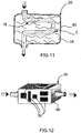
- the exhaust line 1 illustrated in the figure 1 represents the state of the art mentioned in the preamble, this line 1 comprising successively from a multitube exhaust manifold 3 at the output of the power unit 4, a decoupling hose 5, a catalytic converter 6 and two rigid silencers 7 fixed to the vehicle body by elastic suspension lines 8 and interconnected by tubes 9 of stainless steel.
- the two mufflers 7 have been removed and replaced by at least one muffler 12 consisting of a duct 14 which is fixed by rigid fixing lugs 15 to the vehicle body and which acts as a guide for the exhaust gases and as acoustic attenuator for exhaust noise, as will be described hereinafter with reference to Figures 2 to 9 .
- the duct 14 is constituted by at least one internal tubular element 16 which is porous, a thermal and acoustic insulation blanket 18, and a flexible and tight external envelope 20 made of an elastomeric material which holds at a high temperature, this envelope 20 being able to be made of a thermoplastic material such PA 66, or based on an elastomeric material such as VAMAC® or a silicone for example.
- the conduit 14 is constituted by at least one internal tubular element 16 of flexible or rigid type which is preferably metallic to withstand the temperature of the exhaust gas, and which is porous, in particular for acoustic reasons.
- the porosity of the inner tubular element 16 is obtained by piercing openings over substantially its entire length.
- the inner tubular element 16 is constituted by a metal tube 25 pierced with openings 27.
- the openings 27 may be formed by several series of openings, for example three in number 27a, 27b and 27c, which have crossing sections or respectively increasing diameters in the flow direction of the flow of the exhaust gas, in particular to avoid risks of recirculation of the flow of exhaust gases in the mattress 18, as illustrated in FIG. figure 4b .
- These three series of openings 27a, 27b and 27c have for example diameters of 1mm, 2mm and 3mm, respectively.
- the internal tubular element 16 consists of two internal concentric tubes 25a and 25b external, the inner tube 25a extending for example only over a portion of the length of the muffler, of the order of 5 to 30% for example , to create interference capable of destroying the sound waves of the flow of the exhaust gas stream.
- the internal tubular element 16 is constituted by a simple staple ( figure 4d ), with a double staple ( figure 4e ) or by a flat spring with overlapping turns ( figure 3 ), all these elements having communication passages independently of additional openings that can be drilled as in the case of metal tubes of Figures 4a or 4b .
- the inner tubular element 16 is designed as a flat spring 29 with overlapping turns, but this element 16 can be replaced by the one according to one of the embodiments of FIGS. Figures 4a to 4e .
- a refractory fabric 30 may be wound on all or part of the inner tubular element 16, this fabric having a sufficient porosity to allow damping of the acoustic waves by the mattress 18 but while limiting the direct passage of the gases of exhaust to the mat 18 to prevent damage to the outer casing 20.
- This fabric 30 may be made of ceramic fibers, basalt or glass, for example.
- the duct 14 may have at least one protruding protrusion 32 which is formed at its outer casing 20 to create an additional volume 33 which is filled by the material forming the mat 18.
- an absorbent pad 34 may be housed at very low reflection index on the inner wall of the protrusion 32 to obtain a better absorption of noise. This is made possible by the low temperature level of the protrusion 32, which would be impossible to design with a metal silencer according to the prior art.
- the liner 34 may be made of a honeycombed silicone foam, for example.
- compression rings 40 are provided in the mattress 18 to compress it and thus delimit several volumes V adapted to the frequencies to be controlled.
- These rings 40 are elastic, spaced regularly from each other, made of silicone for example, and bear against the outer casing 20.
- the compression of the insulating material on one side and the support on the outer casing 20 on the other side allow to delimit a sealed volume V which creates a volume of acoustic resonance.
- Such rings 40 thus create an incompressible zone and support the weight of the inner tubular element 16 without any risk of creep of the insulating material.
- a baffle 45 is interposed inside the internal tubular element 16 of the duct 14.
- a baffle 45 can be constituted by the assembly of three metal disks, two upstream and downstream lateral disks 47 49 and a central disk 51 , which are arranged perpendicular to the flow direction of the exhaust gas, and two metal connecting tubes 53 and 55 pierced with holes 52 and mounted coaxially with the inner tubular member 16 but of a smaller diameter.
- the upstream side disc 47 has a central opening 57 to the diameter of the two connecting tubes 53 and 55, and openings 59 distributed around the central opening, while the downstream side disc 49 has only a central opening 57 to the diameter of the two connecting tubes 53 and 55.
- the central disc 51 is solid in its central portion to avoid direct communication between the two connecting tubes 53 and 55, but has openings 61 at its periphery.
- a first volume V 1 is defined inside the connecting tube 53, a second annular volume V 2 around the connecting tube 53, a third annular V 3 around the connecting tube 55 and a fourth volume V 4 to inside the connecting tube 55.
- the exhaust gas enters directly on the one hand, in the first volume V 1 through the central opening 57 of the upstream disk 47 and in the second volume V 2 through the holes 52 of the connecting tube 53 and, on the other hand, in the volume V 2 through the holes 59 of the upstream disk 47.
- the exhaust gases pass from the second volume V 2 to the third volume V 3 through the openings 61 of the central disk 51, then enter the fourth volume V4 for the openings 52 of the connecting tube 55 before escaping from the baffle 45 through the central opening 57 of the downstream disc 49.
- baffles 45 can be interposed inside the internal tubular element 16 of the conduit 14 .
- the output of the catalytic converter 6 is provided by a metal tubular element 72, stainless steel for example , whose downstream end 72a is flared to connect to the conduit 14 which has a diameter greater than that of the tubular element 72.
- the inner tubular element 16 is connected by welding to the flared end 72a of the tubular element 72, while the outer casing 20 of the duct 12 is connected by means of a metal cap 75 which is long and of small thickness, whose function is to thermally protect the outer casing 20.
- the cooling fins 77 can be arranged.
- the tubular element 72 can be flattened into a wavy or corrugated shape, as can be seen in FIG. figure 8a .
- the exhaust gases must be rejected at a temperature below 200 ° C for example, while at the entrance to the conduit 14 they may have a temperature of about 500 ° C.
- a metal output device 80 forming a diffuser.
- This output device 80 may comprise at least one generally conical shaped element 82 which is pierced with holes 84, and a tubular outlet member 86 which surrounds and extends the element 82.
- the exhaust gases exit through the holes 84 to enter the the tubular outlet member 86 which has at least one aperture 88 in its wall to allow ambient air inlet to promote the expulsion of the exhaust gas at a moderate temperature.
- This output device 80 also comprises an element 82 but in the form of a star, and an output element 86 which surrounds and extends the element 82 with at least one opening 88 in its wall to allow an air inlet.
- the outer casing 20 of the duct 14 can be made, on at least part of the duct, in the form of a sealed box 90 which is traversed by the internal metal tubular element 16 coated with its refractory fabric 30.
- This box 90 is made in two parts joined to each other after insertion of the inner metal element 16, the box 90 being filled by the thermal and acoustic insulation mat 18.
- the inner metal element 16 can form at least a bend C inside the box 90 to increase the sound insulation of the conduit 14.
- the wall of the box 90 may comprise at least one resonance surface 92 in the form of a membrane for example having its own frequency or frequencies which correspond to some of the frequencies of the frequency spectrum to be attenuated.
- a surface 92 if it comes to be excited, will begin to vibrate and thus dissipate energy so as to contribute effectively to the acoustic insulation of the conduit 14.
- FIG. 13 and 14 there is illustrated a method of mounting a silencer 12 according to the invention in a motor vehicle exhaust line.
- a silencer 12 In general, one manufactures, stores and transports a silencer 12 in a rectilinear form. Then, at the mounting location of the silencer 12, it is deformed according to the geometric configuration that it must take before attaching it to the vehicle body by rigid fixing lugs 15.
- the silencer 12 presents at least two series of corrugations 14a and 14b and it is at these undulations 14a and 14b that the silencer 12 can be bent.
- the conduit 14 had a substantially porous internal metal element 16 over substantially its entire length, but the conduit 14 can also be made in several parts which are assembled in pairs by a substantially smooth tubular metal element which is connected to two adjacent porous metallic elements 16, this smooth element being bent and possibly being able to be coated with a refractory fabric 30, the insulator 18 and the outer envelope 20.
Landscapes
- Engineering & Computer Science (AREA)
- Chemical & Material Sciences (AREA)
- Combustion & Propulsion (AREA)
- Mechanical Engineering (AREA)
- General Engineering & Computer Science (AREA)
- Health & Medical Sciences (AREA)
- Chemical Kinetics & Catalysis (AREA)
- Toxicology (AREA)
- Exhaust Silencers (AREA)
Claims (32)
- Schalldämpfer für eine Abgaslinie eines Motorfahrzeugs, dass er aus mindestens einem Kanal (14) besteht der als Führung für die Abgase dient und als akustischer Dämpfer für die Abgasgeräusche, und der mindestens ein poröses rohrförmiges Metallelement (16), eine zwischenliegende thennische und akustische Isolationsmatte (18) und einen äußeren dichten Mantel (20) aus einem Polymermaterial umfasst, und dadurch, dass der äußere Mantel (20) über zwei Metallkappen (75) dicht an zwei rohrförmige metallische Anschlussvorrichtungen (70, 80) angeschlossen wird,
dadurch gekennzeichnet, dass die zwischenliegende thermische und akustische Isolationsmatte (18) direkt oder mittels eines porösen hitzebeständigen Gewebes (30) das mindestens eine poröse interne rohrförmige Metallelement (16) umgibt. - Schalldämpfer nach Anspruch 1, wobei der Kanal (14) flexibel ist.
- Schalldämpfer nach Anspruch 1 oder 2, wobei das interne rohrförmige Metallelement (16) aus einer Flachfeder (29) mit überlagerten Windungen besteht.
- Schalldämpfer nach Anspruch 1 oder 2, wobei das interne rohrförmige Metallelement (16) aus einer Einfach- oder Doppelschelle besteht.
- Schalldämpfer nach einem der vorherigen Ansprüche, wobei das interne rohrförmige Metallelement (16) flexibel oder starr ist und mit Öffnungen (27) durchbohrt ist.
- Schalldämpfer nach Anspruch 5, wobei die Öffnungen (27) einen zunehmenden Durchmesser in Durchflussrichtung der Abgase aufweist.
- Schalldämpfer nach Anspruch 6, wobei die Öffnungen (27) in mehrere Öffnungsreihen (27a, 27b, 27c) unterteilt sind, wobei jede Öffnungsreihe im Wesentlichen den gleichen Durchmesser aufweist.
- Schalldämpfer nach einem der Ansprüche 5 bis 7, wobei das interne rohrförmige Metallelement (16) aus mindestens zwei konzentrischen internen und äußeren Rohren (25a, 25b) besteht, die mit Öffnungen (27) durchbohrt sind.
- Schalldämpfer nach Anspruch 8, wobei sich das interne Metallrohr (25a) nur über einen Teil der Gesamtlänge des Schalldämpfers erstreckt.
- Schalldämpfer nach einem der vorherigen Ansprüche, wobei das hitzebeständige Gewebe (30) aus Keramik-, Basalt- oder Glasfasern ist.
- Schalldämpfer nach einem der vorherigen Ansprüche, wobei der äußere Mantel (20) des Kanals auf Grundlage eines thermoplastischen Materials, wie z. B. Polyamid 66, oder auf Grundlage eines Elastomermaterials, wie z. B. VAMAC® oder aus einem Silikon ausgeführt ist.
- Schalldämpfer nach einem der vorherigen Ansprüche, wobei der äußere Mantel (20) des Kanals durch einen Extrusionsblasform-Vorgang ausgeführt ist.
- Schalldämpfer nach einem der Ansprüche 1 bis 10, wobei dichte ringförmige Volumen (V) in Längsrichtung in der thermischen und akustischen Isolationsmatte (18) angeordnet sind.
- Schalldämpfer nach Anspruch 13, wobei jedes dichte Zwischenvolumen (V) in der thermischen und akustischen Isolationsmatte (18) durch zwei Kompressionsringe (40) begrenzt ist.
- Schalldämpfer nach Anspruch 14, wobei jeder Kompressionsring (40) elastisch und beispielsweise aus Silikon ausgeführt ist.
- Schalldämpfer nach einem der Ansprüche 1 bis 13, wobei akustische Leitplatten (45) in dem internen Rohrelement (16) des flexiblen Kanals (14) zwischengestellt sind.
- Schalldämpfer nach Anspruch 16, wobei eine akustische Leitplatte (45) aus drei Scheiben (47, 49 und 51) besteht, die senkrecht zur Strömungsachse der Abgase montiert ist, und aus zwei Verbindungsrohren (53, 55) besteht, die Löcher (52) koaxial zu dem internen Rohrelement (16) und mit dem kleinsten Durchmesser aufweist.
- Schalldämpfer nach einem der vorherigen Ansprüche, wobei der äußere und dichte Mantel (20) mindestens eine überstehende Ausstülpung (32) aufweist, um ein zusätzliches Volumen (33) zu schaffen, das durch das Material gefüllt ist, das die Matte (18) bildet.
- Schalldämpfer nach Anspruch 18, wobei die Innenwand der Ausstülpung (32) mit einer absorbierenden Auskleidung (34) beschichtet ist.
- Schalldämpfer nach Anspruch 19, wobei die absorbierende Auskleidung (4) ein wabenförmiger Silikonschaumstoff ist.
- Schalldämpfer nach einem der vorherigen Ansprüche, wobei der flexible Kanal (14) am Einlass an eine rohrförmige Vorrichtung mit aufgeweitetem Metallanschluss (70) angeschlossen wird, der äußere und/oder interne Kühlrippen (77) aufweist, um die Temperatur der Abgase zu reduzieren.
- Schalldämpfer nach einem der vorherigen Ansprüche, wobei der flexible Kanal (14) am Auslass an eine Vorrichtung (80) angeschlossen wird, die einen Diffusor bildet, um die Auslasstemperatur der Abgase zu reduzieren.
- Schalldämpfer nach Anspruch 22, wobei die Auslassvorrichtung (80), die einen Diffusor bildet, mindestens ein Element (82) mit einer generell kegelförmigen Form umfasst, das mit Löchern (84) durchbohrt ist, und ein rohrförmiges Auslasselement (86), das das Element (82) umgibt und verlängert, und dessen Wand mindestens eine Öffnung (88) aufweist, um einen Eintritt von Umgebungsluft zu erlauben.
- Schalldämpfer nach Anspruch 22, wobei die Auslassvorrichtung (80), die einen Diffusor bildet, mindestens ein Element (82) mit einer sternförmigen Form umfasst, und ein rohrförmiges Auslasselement (86), das das Element (82) umgibt und verlängert, und dessen Wand mindestens eine Öffnung (88) aufweist, um einen Eintritt von Umgebungsluft zu erlauben.
- Schalldämpfer nach einem der vorherigen Ansprüche, wobei der äußere dichte Mantel (20) des Schalldämpfer ein Gehäuse (90) bildet, das von dem internen rohrförmigen Metallelement (16) durchquert wird, wobei die zwischenliegende thermische und akustische Isolationsmatte (18) das Gehäuse (90) füllt.
- Schalldämpfer nach Anspruch 25, wobei das interne rohrförmige Metallelement (16) mindestens einen Bogen im Innern des Gehäuses (90) bildet.
- Schalldämpfer nach Anspruch 25 oder 26, wobei das Gehäuse (90) auf seiner Wand mindestens eine Fläche (92) aufweist, die durch eine Resonanzmembran gebildet ist, die auf mindestens eine Frequenz der abzuschwächenden Frequenzspektrums abgestimmt ist.
- Schalldämpfer nach einem der vorherigen Ansprüche, wobei der Schalldämpfer mindestens zwei Kanäle (14) umfasst, die miteinander durch ein möglicherweise gebogenes rohrförmiges Metallelement verbunden sind.
- Schalldämpfer nach Anspruch 28, wobei das rohrförmige Metallelement glatt ist.
- Montageverfahren eines Schalldämpfers, wie er nach einem der vorherigen Ansprüche in einer Abgaslinie eines motorisierten Fahrzeugs definiert ist, dadurch gekennzeichnet, dass es aus dem Herstellen, Lagern und Transportieren des Schalldämpfers mit einer geradlinigen Form, seinem Verformen gemäß einer gegebenen Konfiguration im Moment seiner Montage in die Abgaslinie und seinem Befestigen an der Karosserie des Fahrzeugs mittels starrer Befestigungslaschen besteht.
- Verfahren nach Anspruch 30, wobei der Kanal (14) auf Ebene eines gewellten Bereichs (14a und/oder 14b) des Kanals gebogen ist.
- Verfahren nach Anspruch 30 oder 31, wobei der äußere dichte Mantel (20) des Kanals (14) durch einen Extrusionsblasform-Vorgang ausgeführt ist.
Applications Claiming Priority (2)
| Application Number | Priority Date | Filing Date | Title |
|---|---|---|---|
| FR0400894 | 2004-01-30 | ||
| FR0400894A FR2865766B1 (fr) | 2004-01-30 | 2004-01-30 | Silencieux pour ligne d'echappement d'un moteur de vehicule et son procede de montage |
Publications (2)
| Publication Number | Publication Date |
|---|---|
| EP1559877A1 EP1559877A1 (de) | 2005-08-03 |
| EP1559877B1 true EP1559877B1 (de) | 2019-05-08 |
Family
ID=34639810
Family Applications (1)
| Application Number | Title | Priority Date | Filing Date |
|---|---|---|---|
| EP04293085.9A Expired - Lifetime EP1559877B1 (de) | 2004-01-30 | 2004-12-22 | Schalldämpfer für Abgasleitung eines Kraftfahrzeugmotors und Verfahren zur Montage |
Country Status (5)
| Country | Link |
|---|---|
| US (1) | US20050167192A1 (de) |
| EP (1) | EP1559877B1 (de) |
| JP (1) | JP2005214209A (de) |
| ES (1) | ES2740102T3 (de) |
| FR (1) | FR2865766B1 (de) |
Families Citing this family (17)
| Publication number | Priority date | Publication date | Assignee | Title |
|---|---|---|---|---|
| US7546899B2 (en) * | 2005-10-05 | 2009-06-16 | Arrowhead Products Corporation | Lightweight polymer muffler apparatus and method of making same |
| JP5010138B2 (ja) | 2005-11-24 | 2012-08-29 | トヨタ自動車株式会社 | サブマフラー |
| US20070218790A1 (en) * | 2006-03-16 | 2007-09-20 | Am General Llc | Composite insulation |
| KR100756334B1 (ko) | 2006-07-18 | 2007-09-12 | 주식회사 준비엘 | 자동차용 소음기 |
| DE102007010814A1 (de) * | 2007-03-06 | 2008-09-11 | Arvinmeritor Emissions Technologies Gmbh | Schalldämpfer-Dämmelement, Schalldämpfer sowie Verfahren zur Herstellung eines Schalldämpfers |
| GB2449684B (en) * | 2007-05-31 | 2009-12-30 | Senior Uk Ltd | Flexible exhaust coupling device |
| US20090065295A1 (en) * | 2007-09-11 | 2009-03-12 | Sherikar Sanjay V | Desuperheater muffler |
| US7810609B2 (en) * | 2007-09-26 | 2010-10-12 | Chrysler Group Llc | Muffler |
| EP2232031A2 (de) * | 2007-11-21 | 2010-09-29 | EMCON Technologies LLC | Auslassventilanordnung |
| JP4984084B2 (ja) * | 2008-03-31 | 2012-07-25 | 株式会社三五 | 消音器 |
| US20110186378A1 (en) * | 2008-09-22 | 2011-08-04 | Stebro Psd Ltd. | Open chamber exhaust mufflers and related methods of manufacture and use |
| CN101818673B (zh) * | 2010-04-20 | 2011-11-09 | 东莞市旗丰消声器有限公司 | 一种消声器的制造工艺 |
| DE102011075643A1 (de) * | 2011-05-11 | 2012-11-15 | J. Eberspächer GmbH & Co. KG | Abgasanlagenkomponente |
| US20130170318A1 (en) * | 2011-12-29 | 2013-07-04 | Ii John J. Valenza | Device and method for attenuating acoustic signals |
| GB2551578B (en) * | 2016-06-24 | 2019-12-11 | Jaguar Land Rover Ltd | Conduit for reducing noise |
| BR102016021660A2 (pt) * | 2016-09-21 | 2018-04-10 | Pessoa De Oliveira Maurílio | Arcos espirais metálicos de alto desempenho de conservação de energia térmica e sistema interno de sustentação e resistência ao amassamento |
| EP3415735A1 (de) * | 2017-06-15 | 2018-12-19 | Tru-Flex, LLC | Abgaskopplungssystem und -verfahren |
Family Cites Families (20)
| Publication number | Priority date | Publication date | Assignee | Title |
|---|---|---|---|---|
| US3181647A (en) * | 1965-05-04 | Apparatus for muffling noise and engine exhaust gases | ||
| GB256066A (en) * | 1925-08-25 | 1926-08-05 | Prince Orazio Borghese | Improvements in silencers for internal combustion engines |
| US2718273A (en) * | 1951-10-29 | 1955-09-20 | Albert J Dehaus | Muffler construction |
| FR1272608A (fr) * | 1960-08-19 | 1961-09-29 | Polycarbure | Silencieux pour l'écoulement pulsatoire de gaz |
| US3422855A (en) * | 1965-11-17 | 1969-01-21 | Dow Corning | High temperature fluid conduit |
| US3590945A (en) * | 1970-04-03 | 1971-07-06 | Milo E Murphy | Tuned resonance mufflers |
| US3655010A (en) * | 1970-07-17 | 1972-04-11 | Tenneco Inc | Acoustic conduit with wrinkle section |
| US3730293A (en) * | 1972-05-12 | 1973-05-01 | T Cassel | Exhaust pipe with combined bendable partition |
| GB1441742A (en) * | 1972-08-15 | 1976-07-07 | Smiths Industries Ltd | Tubing |
| SE409484B (sv) * | 1976-08-19 | 1979-08-20 | Collin Lars | Ljuddempare |
| JP3984308B2 (ja) * | 1996-02-21 | 2007-10-03 | イビデン株式会社 | 内燃機関の消音器 |
| FR2758588B1 (fr) * | 1997-01-23 | 1999-02-19 | Hutchinson | Flexible de decouplage monte dans une ligne d'echappement d'un moteur de vehicule automobile |
| DE19750102A1 (de) * | 1997-11-12 | 1999-06-02 | Stankiewicz Gmbh | Gasdurchströmte Leitung mit Schallabsorptionswirkung |
| BR9814184A (pt) * | 1997-11-21 | 2000-10-03 | Stephanus Ferreira | Silenciador |
| US6087445A (en) * | 1998-05-13 | 2000-07-11 | Gherghel; Radu Olimpiu | Polymers containing nylon and halogenated polymer |
| US6298935B1 (en) * | 1999-12-01 | 2001-10-09 | Scambia Industrial Developments Ag | Exhaust system for a motor vehicle and a motor vehicle with the exhaust system |
| WO2001069051A1 (en) * | 2000-03-17 | 2001-09-20 | Coetzee, Magdalena, Petronella | A gas-flow silencer |
| GB0206074D0 (en) * | 2002-03-15 | 2002-04-24 | Smiths Group Plc | Ducting |
| US7159620B2 (en) * | 2002-09-04 | 2007-01-09 | Knauf Insulation Gmbh | Pipe blanket to fit a variety of pipe diameters |
| US6752240B1 (en) * | 2002-11-05 | 2004-06-22 | Brunswick Corporation | Sound attenuator for a supercharged marine propulsion device |
-
2004
- 2004-01-30 FR FR0400894A patent/FR2865766B1/fr not_active Expired - Lifetime
- 2004-12-22 EP EP04293085.9A patent/EP1559877B1/de not_active Expired - Lifetime
- 2004-12-22 ES ES04293085T patent/ES2740102T3/es not_active Expired - Lifetime
-
2005
- 2005-01-14 US US11/036,554 patent/US20050167192A1/en not_active Abandoned
- 2005-01-28 JP JP2005022061A patent/JP2005214209A/ja active Pending
Non-Patent Citations (1)
| Title |
|---|
| None * |
Also Published As
| Publication number | Publication date |
|---|---|
| US20050167192A1 (en) | 2005-08-04 |
| EP1559877A1 (de) | 2005-08-03 |
| ES2740102T3 (es) | 2020-02-05 |
| FR2865766B1 (fr) | 2008-01-04 |
| JP2005214209A (ja) | 2005-08-11 |
| FR2865766A1 (fr) | 2005-08-05 |
Similar Documents
| Publication | Publication Date | Title |
|---|---|---|
| EP1559877B1 (de) | Schalldämpfer für Abgasleitung eines Kraftfahrzeugmotors und Verfahren zur Montage | |
| US7810609B2 (en) | Muffler | |
| US5419127A (en) | Insulated damped exhaust manifold | |
| US7424931B2 (en) | Muffler for a motorcycle | |
| JP5449449B2 (ja) | 排気系部品 | |
| JP2006525471A (ja) | 中低周波数における音響性能を向上させたマフラ | |
| EP1069289B1 (de) | Verbesserung zu einem Entkopplungselement in einer Auspuffanlage eines Kraftfahrzeugmotors | |
| FR2663985A1 (fr) | Silencieux a logement en une piece pour vehicule automobile, conduit faisant partie du silencieux et procede de sa fabrication. | |
| US8191581B2 (en) | Wire tube structure for exhaust component | |
| FR2835018A1 (fr) | Perfectionnement a un flexible de decouplage pour ligne d'echappement d'un moteur de vehicule automobile | |
| EP1780398B1 (de) | Ansaugschalldämpfer für einer Brennkraftmaschine mit Turbolader | |
| CN114174644B (zh) | 车辆排气系统 | |
| US6913112B2 (en) | Noise attenuation assembly | |
| EP1929135B1 (de) | Schalldämpferanordnung und verfahren zur montage eines schalldämpfers | |
| CN110080855B (zh) | 消音器 | |
| FR2473623A1 (fr) | Ensemble de purification catalytique des gaz d'echappement de moteurs a combustion interne d'automobiles et procede de fabrication de cet ensemble | |
| FR2927952A1 (fr) | Paroi insonorisante, en particulier pour nacelle de turboreacteur | |
| JP7502241B2 (ja) | 排気管 | |
| FR2883034A1 (fr) | Collecteur d'echappement a double paroi | |
| FR2857051A1 (fr) | Systeme d'echappement d'un vehicule a moteur comprenant un dispositif catalyseur et/ou un filtre a particules. | |
| JP4307623B2 (ja) | 消音器 | |
| JP7138784B2 (ja) | 触媒装置 | |
| JP4453151B2 (ja) | 排気ガス浄化用触媒コンバータ | |
| JPH10159538A (ja) | 消音器 | |
| WO2006018550A1 (fr) | Dispositif d'echappement a ecran de protection |
Legal Events
| Date | Code | Title | Description |
|---|---|---|---|
| PUAI | Public reference made under article 153(3) epc to a published international application that has entered the european phase |
Free format text: ORIGINAL CODE: 0009012 |
|
| AK | Designated contracting states |
Kind code of ref document: A1 Designated state(s): AT BE BG CH CY CZ DE DK EE ES FI FR GB GR HU IE IS IT LI LT LU MC NL PL PT RO SE SI SK TR |
|
| AX | Request for extension of the european patent |
Extension state: AL BA HR LV MK YU |
|
| 17P | Request for examination filed |
Effective date: 20051205 |
|
| AKX | Designation fees paid |
Designated state(s): DE ES FR IT |
|
| 17Q | First examination report despatched |
Effective date: 20081106 |
|
| GRAP | Despatch of communication of intention to grant a patent |
Free format text: ORIGINAL CODE: EPIDOSNIGR1 |
|
| RIC1 | Information provided on ipc code assigned before grant |
Ipc: F01N 13/20 20100101ALI20180213BHEP Ipc: F01N 1/00 20060101ALI20180213BHEP Ipc: F01N 1/08 20060101AFI20180213BHEP Ipc: F01N 13/16 20100101ALI20180213BHEP Ipc: F01N 13/02 20100101ALI20180213BHEP Ipc: F01N 13/18 20100101ALI20180213BHEP Ipc: F01N 1/10 20060101ALI20180213BHEP Ipc: F01N 1/22 20060101ALI20180213BHEP Ipc: F01N 3/05 20060101ALI20180213BHEP |
|
| INTG | Intention to grant announced |
Effective date: 20180309 |
|
| GRAJ | Information related to disapproval of communication of intention to grant by the applicant or resumption of examination proceedings by the epo deleted |
Free format text: ORIGINAL CODE: EPIDOSDIGR1 |
|
| INTC | Intention to grant announced (deleted) | ||
| GRAP | Despatch of communication of intention to grant a patent |
Free format text: ORIGINAL CODE: EPIDOSNIGR1 |
|
| INTG | Intention to grant announced |
Effective date: 20181004 |
|
| RIC1 | Information provided on ipc code assigned before grant |
Ipc: F01N 1/10 20060101ALI20180213BHEP Ipc: F01N 13/20 20100101ALI20180213BHEP Ipc: F01N 13/02 20100101ALI20180213BHEP Ipc: F01N 1/00 20060101ALI20180213BHEP Ipc: F01N 1/22 20060101ALI20180213BHEP Ipc: F01N 1/08 20060101AFI20180213BHEP Ipc: F01N 13/18 20100101ALI20180213BHEP Ipc: F01N 3/05 20060101ALI20180213BHEP Ipc: F01N 13/16 20100101ALI20180213BHEP |
|
| GRAS | Grant fee paid |
Free format text: ORIGINAL CODE: EPIDOSNIGR3 |
|
| GRAA | (expected) grant |
Free format text: ORIGINAL CODE: 0009210 |
|
| AK | Designated contracting states |
Kind code of ref document: B1 Designated state(s): DE ES FR IT |
|
| REG | Reference to a national code |
Ref country code: DE Ref legal event code: R096 Ref document number: 602004053946 Country of ref document: DE |
|
| REG | Reference to a national code |
Ref country code: ES Ref legal event code: FG2A Ref document number: 2740102 Country of ref document: ES Kind code of ref document: T3 Effective date: 20200205 |
|
| REG | Reference to a national code |
Ref country code: DE Ref legal event code: R097 Ref document number: 602004053946 Country of ref document: DE |
|
| PLBE | No opposition filed within time limit |
Free format text: ORIGINAL CODE: 0009261 |
|
| STAA | Information on the status of an ep patent application or granted ep patent |
Free format text: STATUS: NO OPPOSITION FILED WITHIN TIME LIMIT |
|
| 26N | No opposition filed |
Effective date: 20200211 |
|
| P01 | Opt-out of the competence of the unified patent court (upc) registered |
Effective date: 20230526 |
|
| PGFP | Annual fee paid to national office [announced via postgrant information from national office to epo] |
Ref country code: IT Payment date: 20231228 Year of fee payment: 20 Ref country code: FR Payment date: 20231221 Year of fee payment: 20 Ref country code: DE Payment date: 20231214 Year of fee payment: 20 |
|
| PGFP | Annual fee paid to national office [announced via postgrant information from national office to epo] |
Ref country code: ES Payment date: 20240124 Year of fee payment: 20 |
|
| REG | Reference to a national code |
Ref country code: DE Ref legal event code: R071 Ref document number: 602004053946 Country of ref document: DE |
|
| REG | Reference to a national code |
Ref country code: ES Ref legal event code: FD2A Effective date: 20250102 |
|
| PG25 | Lapsed in a contracting state [announced via postgrant information from national office to epo] |
Ref country code: ES Free format text: LAPSE BECAUSE OF EXPIRATION OF PROTECTION Effective date: 20241223 |
|
| PG25 | Lapsed in a contracting state [announced via postgrant information from national office to epo] |
Ref country code: ES Free format text: LAPSE BECAUSE OF EXPIRATION OF PROTECTION Effective date: 20241223 |