EP1559643B1 - Scheibenbremsenschloss für Motorräder - Google Patents
Scheibenbremsenschloss für Motorräder Download PDFInfo
- Publication number
- EP1559643B1 EP1559643B1 EP05290230A EP05290230A EP1559643B1 EP 1559643 B1 EP1559643 B1 EP 1559643B1 EP 05290230 A EP05290230 A EP 05290230A EP 05290230 A EP05290230 A EP 05290230A EP 1559643 B1 EP1559643 B1 EP 1559643B1
- Authority
- EP
- European Patent Office
- Prior art keywords
- shaft
- lid
- posterior
- brake disc
- anterior
- Prior art date
- Legal status (The legal status is an assumption and is not a legal conclusion. Google has not performed a legal analysis and makes no representation as to the accuracy of the status listed.)
- Expired - Lifetime
Links
- 230000006835 compression Effects 0.000 claims description 16
- 238000007906 compression Methods 0.000 claims description 16
- 238000005192 partition Methods 0.000 claims description 12
- 238000003780 insertion Methods 0.000 claims description 8
- 230000037431 insertion Effects 0.000 claims description 8
- 230000000149 penetrating effect Effects 0.000 claims description 2
- 238000007373 indentation Methods 0.000 description 8
- 230000000994 depressogenic effect Effects 0.000 description 7
- 208000031968 Cadaver Diseases 0.000 description 6
- 230000000903 blocking effect Effects 0.000 description 4
- 230000000284 resting effect Effects 0.000 description 2
- 240000008042 Zea mays Species 0.000 description 1
- 210000000038 chest Anatomy 0.000 description 1
- -1 dirt Substances 0.000 description 1
- 239000000428 dust Substances 0.000 description 1
- 230000000717 retained effect Effects 0.000 description 1
- XLYOFNOQVPJJNP-UHFFFAOYSA-N water Substances O XLYOFNOQVPJJNP-UHFFFAOYSA-N 0.000 description 1
Images


Classifications
-
- B—PERFORMING OPERATIONS; TRANSPORTING
- B62—LAND VEHICLES FOR TRAVELLING OTHERWISE THAN ON RAILS
- B62H—CYCLE STANDS; SUPPORTS OR HOLDERS FOR PARKING OR STORING CYCLES; APPLIANCES PREVENTING OR INDICATING UNAUTHORIZED USE OR THEFT OF CYCLES; LOCKS INTEGRAL WITH CYCLES; DEVICES FOR LEARNING TO RIDE CYCLES
- B62H5/00—Appliances preventing or indicating unauthorised use or theft of cycles; Locks integral with cycles
- B62H5/14—Appliances preventing or indicating unauthorised use or theft of cycles; Locks integral with cycles preventing wheel rotation
- B62H5/18—Appliances preventing or indicating unauthorised use or theft of cycles; Locks integral with cycles preventing wheel rotation acting on a braking device
Definitions
- the present invention relates to a padlock device specially designed to prevent the rotation of the wheel of a motorcycle, which is placed in the brake disc thereof so that, in trying to turn the wheel, it comes to stop against chassis elements.
- this type of padlock is constituted (see for example the prior art document US2003 / 0188938) of a locking body which is provided with a groove for insertion of the brake disk and in which, transversely to said disc, is capable of penetrating a lock which passes through one of the usual holes of said brake disc and is actuated by a key lock mechanism which is installed within the locking body and which has cover means for covering access for the key when not acting on the lock.
- the device now proposed has a particular constitution that includes a shaft, a folding lid and a helical spring compression and torsion; the shaft having an insertion fit with axial sliding in the locking body and, with respect to the direction of this insertion, this shaft has a free anterior end and a rear end which is incorporated an axial button, and this assembly of the shaft is formed between two sides, anterior and posterior, of a cavity dug in the body, wherein the shaft has an axial sliding capacity between each of the depressed and unpressed positions, said rear side having an orifice which has a sliding fit relative to the contour of the shaft and whose anterior side has a base with reciprocal anti-rotation means of other means existing in said front end of said sliding shaft which has, in its axial alignment, anterior and posterior prominences such as: the anterior prominence has a front ramp as well as a rear wall and is likely to pass widely through any e two indentations, a first and a second, diametrically opposite said orifice; and the posterior
- the folding lid is rotatably mounted in the sliding shaft with the ability to adopt respective closing and opening positions in which the access of the key to the lock is covered or uncovered, these positions being rotatably spaced a quarter of a turn between them and corresponding to said positions not depressed and depressed axial button.
- the folding lid has two bearings, anterior and posterior, which are respectively leaned to said sides of said body cavity and which each have a hole, anterior and posterior, the posterior hole having two notches, a first and a second, which in position of closing of the folding lid remain respectively aligned with the notches of the orifice on the posterior side of said cavity, while the first notch of said posterior hole and the first indentation of the orifice of the posterior side remain aligned with the anterior and posterior prominences of the 'tree.
- the folding lid has two walls, anterior and posterior, which are placed radially with respect to the shaft so that, in open lid position, the posterior prominence remains resting against the posterior bearing and, in closed lid position this posterior prominence remains in the first indentation of the posterior hole, while the anterior prominence remains applied against the face of the posterior partition which looks towards the anterior septum.
- Said compression and torsion spring has one end anchored in said shaft and its other end is applied in said base on the anterior side of said cavity and at this point it has a radial extension which remains applied to the inside of the lid and pushes in the direction of said open position thereof, and which remains confined between said anterior bearing and said anterior wall of the lid.
- This simple composition based on three unique pieces offers simple automatic operation and dresser.
- the closing position of the folding lid is held against the elastic torsion pulse of the compression and torsion spring, since the posterior prominence remains through the first indentation of the posterior hole of the posterior bearing and the shaft can not rotate; in this position the shaft, and therefore the button, can not come out because the anterior prominence remains applied against the posterior wall of the lid by the elastic extension action of the spring; the fact that this anterior prominence is situated in this side of the anterior partition is due to the fact that during the initial assembly there was an elastic jump of the anterior prominence in relation to the anterior partition, with a maneuver which is favored by the ramp before this previous prominence.
- the opening position is achieved by simply pressing the button, then, the posterior prominence exits the first notch and the axial extension of the compression and torsion spring releases a stored torsional elastic energy which automatically causes the opening of the lid; releasing the button the posterior prominence remains pressed against the posterior bearing and maintains the depressed position of the button.
- this device consists of a shaft (5), a cover foldable (6) as well as a compression coil spring (7).
- Said shaft (5) has an insertion fit with axial sliding and rotational locking in the locking body (1) and, with respect to the direction of this insertion, this shaft (5) has a free anterior end and a posterior end where is incorporated an axial button (8).
- the mounting of the shaft (5) is carried out between two sides, anterior (9) and posterior (10), of a cavity (11) hollowed out in the body (1), where the shaft (5) has a capacity axial sliding between each of the depressed and unpressed positions, the posterior side (10) of said cavity having an orifice (12) which has a sliding fit relative to the contour of the shaft (5) and whose anterior side (9) ) has a base (13) for said front end of a said sliding shaft (5) which has axially aligned, anterior (14) and posterior (15) protuberances and such that the front projection (14) has a forward ramp (16) and a rear wall (17) and is capable of passing widely through any of two notches, a first (18) and a second (19), diametrically opposite said orifice (12); and the posterior prominence (15) is capable of passing through said first (18) and second (19) indentations, and has an anterior face (20) as well as a posterior extension (21) which is scaled down and adjusted through relative to said indentations (18, 19).
- Said folding lid (6) is rotatably mounted in the sliding shaft (5) with the capacity to adopt the respective positions of closure and opening in which access of the key of the lock is covered or uncovered. These positions are rotatably spaced a quarter of a turn between them and correspond to said non-depressed and depressed positions of the axial button (8), and the folding lid (6) has two bearings, anterior (22) and posterior (23), which are respectively backed to said sides (9 and 10) of the cavity (11) of the body (1) and which each have a hole, anterior (24) and posterior (25) , the posterior hole (25) having two notches, a first (26) and a second (27), which in the closed position of the folding lid (6) remain respectively aligned with the notches (18, 19) of the orifice ( 12) on the posterior side (10) of said cavity (11), while the first notch (18) and the first notch (26) remain aligned with the anterior (14) and posterior (15) protuberances of the shaft (5).
- the folding lid (6) has two walls, anterior (28) and posterior (29), which are placed radially with respect to the shaft (5) so that, in the lid position ( 6), the posterior prominence (15) remains resting against the posterior bearing (23) and, in the closed lid position (6), this posterior prominence (15) remains through the first notch (26) of the posterior hole ( 25) while the anterior protrusion (14) remains applied against the face of the posterior partition (29) looking towards the anterior wall (28), and said compression and torsion spring (7) has an anchored end in said shaft (5) and its other end is applied in said base (13) on the anterior side (9) of said cavity (11), where it has a radial extension (30) which remains applied inside the lid ( 6) pushing said open position of this one i and remaining confined between said anterior bearing (22) and said anterior partition (28) of the lid (6).
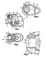
- the composition of the blocking body (1) is illustrated in FIGS. 1 to 4; that of the shaft (5) with button (8), by means of FIGS. 5 and 7 to 10; that of the lid (6), by means of FIGS. 6 and 11 to 13, and that of the spring helical compression and torsion (7), by means of FIG.
- FIGS. 15 to 18 The functionality of the device is illustrated by means of FIGS. 15 to 18, in conjunction with the previous ones.
- Figures 15 and 16 refer to the closed lid position (6); in this position, the spring (7) pushes in the direction of the arrow, so that the posterior extension (21) of the posterior prominence (15) remains nested in the first notch (26) of the posterior hole (25) of the rear bearing (23) and the rear wall (17) of the anterior prominence (14) abuts against the posterior wall (29).
- Figures 17 and 18 refer to the open lid position (6); this position is obtained by pressing the button (8) in the direction indicated by the arrow, which compresses the spring (7) until said posterior prominence (15) comes from the first notch (26) and the lid (6) opens driven by the radial extension of said compression and torsion spring (7).
- the ramp, rear (16) of the anterior prominence (14) has the sole purpose of facilitating the spring jump to overcome the posterior partition (29) during the initial operation of mounting the shaft (5) in the body (1). And this anterior partition (28) is intended to retain the radial extension (30) of the spring (7) between itself and the front bearing (22) of the cover (6).
- the first notch (18) of the orifice (12) of the posterior side (10) of the cavity (11) of the body (1) is intended to allow the passage of the anterior (14) and posterior (15) protuberances.
- the second notch (19) of said orifice (12) and the second notch (27) of the posterior hole (25) of the posterior bearing (23) of the lid (6) serve to facilitate the initial assembly, the shaft (5) being rotated 90 ° in the opposite direction to that of the opening of the lid (6) so that said protuberances (14, 15) do not come into contact with the anterior (28) and posterior (29) partitions of this except the spring jump cited between the anterior prominence (14) and the anterior septum (28).
- the shaft (5) includes anti-rotational means consisting of a button (8) with an extended tear-shaped configuration which is located and operatively plays in a cavity (31) formed in the blocking body (1).
- said shaft (5) is hollow and said compression and torsion spring (7) is installed inside the hollow interior of the shaft (5), where it is still located. end anchored and where its other end remains applied to the portion of the base (13) surrounded by the crown molded therein.
Landscapes
- Engineering & Computer Science (AREA)
- Mechanical Engineering (AREA)
- Pivots And Pivotal Connections (AREA)
Claims (6)
- Motorradscheibenbremsenschloss, mit einem Sperrkörper (1), welcher mit einer Nut (2) versehen ist, die zum Einführen einer Bremsscheibe (3) bestimmt ist und in die quer zu der Bremsscheibe ein Riegel (4) einzudringen vermag, der eines der üblichen Löcher der Bremsscheibe (3) durchquert und durch einen Schlüsselschließmechanismus betätigt wird, der in dem Sperrkörper (1) angebracht ist und bedienbare Abdeckmittel besitzt, um den Zugang für den Schlüssel zu verdecken, wenn das Schloss nicht betätigt wird,
dadurch gekennzeichnet, dass es eine Welle (5), einen Klappdeckel (6) sowie eine Schraubendruck- und Torsionsfeder (7) umfasst, wobei die Welle (5) in dem Sperrkörper (1) durch axiales Einschieben und Drehverriegelung montiert ist und bezogen auf die Einführrichtung ein freies vorderes Ende und ein hinteres Ende besitzt, an dem ein axialer Knopf (8) eingefügt ist, wobei die Montage der Welle (5) zwischen zwei Seiten, einer vorderen (9) und einer hinteren (10), einer in dem Körper (1) ausgebildeten Höhlung (11) erfolgt, wo die Welle (5) jeweils zwischen einer eingedrückten und einer nicht eingedrückten Position axial zu gleiten vermag, wobei die hintere Seite (10) eine Öffnung (12) aufweist, die in Bezug auf die Kontur der Welle (5) eine Gleitpassung hat, und die vordere Seite (9) eine Auflage (13) für das vordere Ende der Gleitwelle (5) aufweist, die in ihrer axialen Flucht einen vorderen (14) und einen hinteren (15) Vorsprung hat, derart, dass der vordere Vorsprung (14) eine vordere Schräge (16) sowie eine rückwärtige Wand (17) aufweist und irgendeine der beiden Aussparungen, eine erste (18) bzw. eine zweite (19), mühelos zu passieren vermag, die der Öffnung (12) diametral gegenüberliegen, und der hintere Vorsprung (15) die erste (18) und die zweite (19) Aussparung zu durchqueren vermag und eine Vorderseite (20) sowie eine hintere Verlängerung (21) aufweist, die sich verjüngend und bezüglich der Aussparungen (18, 19) mit Durchgangspassung abgestuft ist, wobei der Klappdeckel (6) auf der Gleitwelle (5) drehbar montiert ist und eine geschlossene bzw. eine geöffnete Stellung einzunehmen vermag, in der der Zugang für Schlüssel des Schlosses verdeckt ist bzw. freiliegt, wobei diese Stellungen durch Drehen um eine Vierteldrehung voneinander abweichen und der nicht eingedrückten bzw. der eingedrückten Position des axialen Knopfs (8) entsprechen, und der Klappdeckel (6) zwei Lager besitzt, ein vorderes (22) und ein hinteres (23), die jeweils an den Seiten (9 und 10) der Höhlung (11) des Körpers (1) anliegen und ein vorderes (24) bzw. ein hinteres (25) Loch besitzen, wobei das hintere Loch (25) zwei Aussparungen aufweist, eine erste (26) und eine zweite (27), die in geschlossener Stellung des Klappdeckels (6) jeweils mit den Aussparungen (18, 19) der Öffnung (12) der hinteren Seite (10) der Höhlung (11) fluchtend angeordnet sind, während die erste Aussparung (18) der Öffnung und die erste Aussparung (26) des hinteren Lochs mit dem vorderen (14) und dem hinteren (15) Vorsprung der Welle (5) fluchtend angeordnet bleiben, und wobei der Klappdeckel (6) zwischen den Lagern (22, 23) zwei Trennwände besitzt, eine vordere (28) und eine hintere (29), die bezüglich der Welle (5) radial angeordnet sind, derart, dass der hintere Vorsprung (15) bei geöffnetem Deckel (6) in Anlage am hinteren Lager (23) verbleibt und der hintere Vorsprung (15) bei geschlossenem Deckel durchgehend in der ersten Aussparung (26) des hinteren Lochs (25) verbleibt, während der vordere Vorsprung (14) an der Seite der hinteren Trennwand (29), die zur vorderen Trennwand (28) gewandt ist, in Anlage bleibt, und wobei die Schraubendruck- und Torsionsfeder (7) ein In der Welle (5) verankertes Ende hat, und ihr anderes Ende an der Auflage (13) der vorderen Seite (9) der Höhlung (11) anliegt, wo sie eine radiale Erweiterung (30) aufweist, die innen im Deckel (6) in Anlage bleibt und hierbei in Richtung der geöffneten Deckelstellung drückt und zwischen dem vorderen Lager (22) und der vorderen Trennwand (28) des Deckels (6) eingeschlossen bleibt. - Motorradscheibenbremsenschloss nach dem vorhergehenden Anspruch,
dadurch gekennzeichnet, dass die Auflage (13) für das vordere Ende der Welle (5) eine kreisringförmige Vertiefung ist, die in der vorderen Seite (9) ausgebildet ist. - Motorradscheibenbremsenschloss nach den vorhergehenden Ansprüchen,
dadurch gekennzeichnet, dass die Welle (5) hohl ist. - Motorradscheibenbremsenschloss nach Anspruch 3,
dadurch gekennzeichnet, dass die Druck- und Torsionsfeder (7) im hohlen Innenraum der Welle (5) angebracht ist, wo ihr verankertes Ende platziert bleibt und wo ihr anderes Ende an dem Teil der Auflage (13) in Anlage bleibt, das von dem darin ausgebildeten Kreisring umgeben ist. - Motorradscheibenbremsenschloss nach den vorhergehenden Ansprüchen,
dadurch gekennzeichnet, dass die Welle (5) drehsperrende Mittel umfasst. - Motorradscheibenbremsenschloss nach Anspruch 5,
dadurch gekennzeichnet, dass die drehsperrenden Mittel der Welle (5) aus einem Knopf (8) mit einer gestreckten, tropfenförmigen Ausbildung bestehen, der in einer in dem Sperrkörper (1) ausgebildeten Höhlung (31) betriebsbereit mit Spiel angeordnet ist.
Applications Claiming Priority (2)
| Application Number | Priority Date | Filing Date | Title |
|---|---|---|---|
| ES200400216U | 2004-02-02 | ||
| ES200400216U ES1056569Y (es) | 2004-02-02 | 2004-02-02 | Dispositivo de candado de bloqueo rotatorio para disco de freno de motocicletas. |
Publications (2)
| Publication Number | Publication Date |
|---|---|
| EP1559643A1 EP1559643A1 (de) | 2005-08-03 |
| EP1559643B1 true EP1559643B1 (de) | 2006-06-07 |
Family
ID=32050394
Family Applications (1)
| Application Number | Title | Priority Date | Filing Date |
|---|---|---|---|
| EP05290230A Expired - Lifetime EP1559643B1 (de) | 2004-02-02 | 2005-02-02 | Scheibenbremsenschloss für Motorräder |
Country Status (2)
| Country | Link |
|---|---|
| EP (1) | EP1559643B1 (de) |
| ES (1) | ES1056569Y (de) |
Family Cites Families (5)
| Publication number | Priority date | Publication date | Assignee | Title |
|---|---|---|---|---|
| FR2702728A1 (fr) * | 1993-03-19 | 1994-09-23 | Carreras Jacques | Antivol perfectionné pour motocyclette équipée d'un disque de frein ajouré. |
| FR2705077B1 (fr) * | 1993-05-12 | 1995-08-04 | Jouvin Pleintube Jl | Dispositif antivol pour motocycle. |
| US5916279A (en) * | 1997-12-11 | 1999-06-29 | Shieh; Jin-Ren | Motorcycle disk brake lock |
| CN2427398Y (zh) * | 2000-05-26 | 2001-04-25 | 李吉源 | 碟刹盘锁具 |
| US6553793B1 (en) * | 2002-05-16 | 2003-04-29 | Tian-Yuan Chen | Motorcycle disc brake lock |
-
2004
- 2004-02-02 ES ES200400216U patent/ES1056569Y/es not_active Expired - Fee Related
-
2005
- 2005-02-02 EP EP05290230A patent/EP1559643B1/de not_active Expired - Lifetime
Also Published As
| Publication number | Publication date |
|---|---|
| EP1559643A1 (de) | 2005-08-03 |
| ES1056569Y (es) | 2004-07-16 |
| ES1056569U (es) | 2004-04-01 |
Similar Documents
| Publication | Publication Date | Title |
|---|---|---|
| EP1169955B1 (de) | Deckelverriegelungsvorrichtung | |
| FR2849088A1 (fr) | Cadenas | |
| FR2789717A1 (fr) | Serrure en trois parties, pour ouvrant de vehicule automobile | |
| CH642137A5 (fr) | Serrure de surete a broche culbuteuse. | |
| EP1030012B1 (de) | Kraftfahrzeugschloss mit energiespeichernder Entriegelungsvorrichtung | |
| FR2817895A1 (fr) | Dispositif d'embrayage pour serrurerie | |
| CA1265693A (fr) | Dispositif de verrouillage de tampon de regard de chaussee | |
| EP3464762A1 (de) | Vorrichtung zum verriegeln und entriegeln einer schachtabdeckung auf einem rahmen mittels eines schlüssels mit der option einer automatischen schlüssellosen verriegelung dieser schachtabdeckung auf dem rahmen | |
| FR2727152A1 (fr) | Dispositif de verrouillage commande par carte magnetique servant de cle | |
| FR2823128A3 (fr) | Patin a roulettes pliantes | |
| FR2686118A1 (fr) | Mecanisme de serrure pour porte ou abattant. | |
| EP1559643B1 (de) | Scheibenbremsenschloss für Motorräder | |
| EP2565353B1 (de) | Vorrichtung zum Verriegeln und Entriegeln mit Hilfe eines Schlüssels einer Abdeckung auf einem Rahmen mit integrierter Verschlusseinlage eines Öffnungselements der Abdeckung für das Einführen des Schlüssels | |
| EP4108856B1 (de) | Steuerungsvorrichtung eines verriegelungs-/entriegelungssystems eines öffnungsflügels und entsprechender tür-/fensterrahmen | |
| EP3523488B1 (de) | Betätigungsvorrichtung für spülkasten mit drehwähler | |
| FR2612976A1 (fr) | Serrure a mecanisme de verrouillage-deverrouillage a l'aide d'un electro-aimant | |
| FR2858001A1 (fr) | Serrure a pene dormant, manoeuvrable par bouton ou clef | |
| FR2919364A3 (fr) | Dispositif d'embrayage avec fonction anti-panique pour verrous electromecaniques | |
| FR2789718A1 (fr) | Serrure a condamnation enfant, pour ouvrant de vehicule automobile | |
| FR2766859A1 (fr) | Serrure de loquet | |
| FR2478719A1 (fr) | Serrure a pene dormant transversal a verrouillage automatique | |
| FR2730755A1 (fr) | Organe de manoeuvre notamment poignee equipe de moyens pour rendre son utilisation selective constituant une securite pour enfant | |
| FR2869339A1 (fr) | Poignee de cremone a serrure pouvant etre ouverte depuis l'interieur lorsque la serrure est verrouillee | |
| CH294220A (fr) | Serrure à entailler. | |
| WO2020043558A1 (fr) | Mécanisme de verrouillage d'un ouvrant contre un dormant |
Legal Events
| Date | Code | Title | Description |
|---|---|---|---|
| PUAI | Public reference made under article 153(3) epc to a published international application that has entered the european phase |
Free format text: ORIGINAL CODE: 0009012 |
|
| AK | Designated contracting states |
Kind code of ref document: A1 Designated state(s): AT BE BG CH CY CZ DE DK EE ES FI FR GB GR HU IE IS IT LI LT LU MC NL PL PT RO SE SI SK TR |
|
| AX | Request for extension of the european patent |
Extension state: AL BA HR LV MK YU |
|
| 17P | Request for examination filed |
Effective date: 20050805 |
|
| GRAP | Despatch of communication of intention to grant a patent |
Free format text: ORIGINAL CODE: EPIDOSNIGR1 |
|
| RIN1 | Information on inventor provided before grant (corrected) |
Inventor name: MUERZA, ALFREDOC/O LUMA INDUSTRIES S.A. |
|
| GRAS | Grant fee paid |
Free format text: ORIGINAL CODE: EPIDOSNIGR3 |
|
| AKX | Designation fees paid |
Designated state(s): BE FR GR IT NL |
|
| GRAA | (expected) grant |
Free format text: ORIGINAL CODE: 0009210 |
|
| REG | Reference to a national code |
Ref country code: DE Ref legal event code: 8566 |
|
| AK | Designated contracting states |
Kind code of ref document: B1 Designated state(s): BE FR GR IT NL |
|
| PLBE | No opposition filed within time limit |
Free format text: ORIGINAL CODE: 0009261 |
|
| STAA | Information on the status of an ep patent application or granted ep patent |
Free format text: STATUS: NO OPPOSITION FILED WITHIN TIME LIMIT |
|
| 26N | No opposition filed |
Effective date: 20070308 |
|
| PG25 | Lapsed in a contracting state [announced via postgrant information from national office to epo] |
Ref country code: GR Free format text: LAPSE BECAUSE OF FAILURE TO SUBMIT A TRANSLATION OF THE DESCRIPTION OR TO PAY THE FEE WITHIN THE PRESCRIBED TIME-LIMIT Effective date: 20060908 |
|
| PGFP | Annual fee paid to national office [announced via postgrant information from national office to epo] |
Ref country code: NL Payment date: 20090220 Year of fee payment: 5 |
|
| PGFP | Annual fee paid to national office [announced via postgrant information from national office to epo] |
Ref country code: BE Payment date: 20090102 Year of fee payment: 5 |
|
| BERE | Be: lapsed |
Owner name: LUMA INDUSTRIAS, S.A. Effective date: 20100228 |
|
| REG | Reference to a national code |
Ref country code: NL Ref legal event code: V1 Effective date: 20100901 |
|
| PG25 | Lapsed in a contracting state [announced via postgrant information from national office to epo] |
Ref country code: NL Free format text: LAPSE BECAUSE OF NON-PAYMENT OF DUE FEES Effective date: 20100901 |
|
| PG25 | Lapsed in a contracting state [announced via postgrant information from national office to epo] |
Ref country code: BE Free format text: LAPSE BECAUSE OF NON-PAYMENT OF DUE FEES Effective date: 20100228 |
|
| PGFP | Annual fee paid to national office [announced via postgrant information from national office to epo] |
Ref country code: IT Payment date: 20080228 Year of fee payment: 4 |
|
| PGFP | Annual fee paid to national office [announced via postgrant information from national office to epo] |
Ref country code: FR Payment date: 20120221 Year of fee payment: 8 |
|
| REG | Reference to a national code |
Ref country code: FR Ref legal event code: ST Effective date: 20131031 |
|
| PG25 | Lapsed in a contracting state [announced via postgrant information from national office to epo] |
Ref country code: FR Free format text: LAPSE BECAUSE OF NON-PAYMENT OF DUE FEES Effective date: 20130228 |