EP1559643A1 - Scheibenbremsenschloss für Motorräder - Google Patents
Scheibenbremsenschloss für Motorräder Download PDFInfo
- Publication number
- EP1559643A1 EP1559643A1 EP05290230A EP05290230A EP1559643A1 EP 1559643 A1 EP1559643 A1 EP 1559643A1 EP 05290230 A EP05290230 A EP 05290230A EP 05290230 A EP05290230 A EP 05290230A EP 1559643 A1 EP1559643 A1 EP 1559643A1
- Authority
- EP
- European Patent Office
- Prior art keywords
- posterior
- anterior
- shaft
- lid
- prominence
- Prior art date
- Legal status (The legal status is an assumption and is not a legal conclusion. Google has not performed a legal analysis and makes no representation as to the accuracy of the status listed.)
- Granted
Links
- 230000006835 compression Effects 0.000 claims abstract description 17
- 238000007906 compression Methods 0.000 claims abstract description 17
- 230000000994 depressogenic effect Effects 0.000 claims description 13
- 238000007373 indentation Methods 0.000 claims description 13
- 238000005192 partition Methods 0.000 claims description 13
- 230000000903 blocking effect Effects 0.000 claims description 10
- 238000003780 insertion Methods 0.000 claims description 9
- 230000037431 insertion Effects 0.000 claims description 9
- 230000000284 resting effect Effects 0.000 claims description 2
- 208000031968 Cadaver Diseases 0.000 description 6
- 240000008042 Zea mays Species 0.000 description 1
- -1 dirt Substances 0.000 description 1
- 239000000428 dust Substances 0.000 description 1
- 230000000717 retained effect Effects 0.000 description 1
- XLYOFNOQVPJJNP-UHFFFAOYSA-N water Substances O XLYOFNOQVPJJNP-UHFFFAOYSA-N 0.000 description 1
Images

Classifications
-
- B—PERFORMING OPERATIONS; TRANSPORTING
- B62—LAND VEHICLES FOR TRAVELLING OTHERWISE THAN ON RAILS
- B62H—CYCLE STANDS; SUPPORTS OR HOLDERS FOR PARKING OR STORING CYCLES; APPLIANCES PREVENTING OR INDICATING UNAUTHORIZED USE OR THEFT OF CYCLES; LOCKS INTEGRAL WITH CYCLES; DEVICES FOR LEARNING TO RIDE CYCLES
- B62H5/00—Appliances preventing or indicating unauthorised use or theft of cycles; Locks integral with cycles
- B62H5/14—Appliances preventing or indicating unauthorised use or theft of cycles; Locks integral with cycles preventing wheel rotation
- B62H5/18—Appliances preventing or indicating unauthorised use or theft of cycles; Locks integral with cycles preventing wheel rotation acting on a braking device
Definitions
- the present invention relates to a device for padlock specially designed to prevent the rotation of the wheel of a motorcycle, which is placed in the disc of brake of it so that, trying to do turn the wheel, it comes up against elements of the frame.
- this type of padlock consists of a blocking body which is provided with a groove for the insertion of the brake disc and in which, transversely to said disk, is likely to penetrate a lock that passes through one of the usual holes brake disc and is operated by a mechanism of key lock that is installed within the lock body and who has cover means to cover access for the key when not acting on the lock.
- the device now proposed has a special constitution which includes a shaft, a folding lid and a spring helical compression and torsion; the tree having a insertion fitting with axial sliding in the body blocking and, in relation to the meaning of that insertion, that tree has a free anterior end as well as a posterior end where is incorporated an axial button, and this assembly of the tree is carried out between two sides, anterior and posterior, of a cavity dug in the body, where the shaft has an axial sliding capacity between each of the positions depressed and not depressed, said side posterior having an orifice that has a sliding fit relative to the contour of the tree and whose side prior to a base with anti-rotatory means reciprocally other means existing in the said anterior end of said sliding shaft which has, in its axial alignment, previous prominences and posterior such as: anterior prominence has a front ramp as well as a rear wall and is likely to go through any of two indentations, a first and a second, diametrically opposite said orifice; and prominence
- the folding lid is rotatably mounted in sliding shaft with capacity to adopt respective positions of closure and opening in which the access of the key to the lock covers or discovers itself, these positions being distant from rotate one quarter of a turn between them and corresponding to said positions not depressed and depressed axial button.
- the folding lid has two bearings, front and back, which are backed respectively to said sides of said body cavity and who each have a hole, anterior and posterior, the posterior hole with two indentations, a first and a second, which in the closed position of the lid foldable respectively remain aligned with the notches in the hole on the posterior side of the cavity, whereas the first notch of said hole posterior and the first notch of the orifice on the side posterior remain aligned with the prominences anterior and posterior of the tree.
- the folding lid has two partitions, anterior and posterior, which are placed radially relative to the shaft so that, in position of open lid, posterior prominence remains supported against the posterior bearing and, in the lid position closed, this posterior prominence remains in the first indentation of the posterior hole while the anterior prominence remains applied against the face of the posterior partition looking towards the anterior partition.
- Said helical spring of compression and twisting has an end anchored in said shaft and its other end is applied in said base on the anterior side of said cavity and, at this place, it has a radial extension that remains applied inside the lid and pushes into the sense of said opening position thereof, and which remains confined between the said previous level and the said front wall of the lid.
- This simple composition based on three pieces unique offers simple automatic operation and dresser.
- the closing position of the folding lid is held against the elastic torsion pulse of the compression spring and torsion because the prominence posterior remains through the first notch of the posterior hole of the posterior bearing and the shaft can not turn; in this position the tree, and by therefore the button, can not go out because the anterior prominence remains applied against the septum posterior of the lid by the extension action elastic spring; the fact that this prominence front is located in this side of the partition earlier is due to the fact that during the initial there was an elastic jump of prominence anterior to the anterior septum, with a maneuver that is favored by the ramp before this anterior prominence.
- the opening position is obtained by simply pressing the button, then, the posterior prominence comes out of the first notch and the axial extension of the compression and torsion spring releases a stored torsional elastic energy that automatically causes the lid to open; in releasing the button the posterior prominence remains leaning against the posterior bearing and maintains the depressed position of the button.
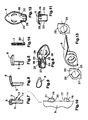
- a mode of execution preferred embodiment of the invention corresponding to a device rotary lock for motorcycle brake disc which responds to a general composition that includes a blocking body (1) having a groove (2) intended for the insertion of the brake disc (3) and into which, transversely to this one, is likely to to enter a bolt (4) through one of the holes said brake disc (3) and is actuated by a key lock mechanism that is installed within the blocking body (1) and having passable means coverage of access for the key, when one does not act on the lock.
- this device consists of a shaft (5), a cover foldable (6) as well as a helical spring of compression (7).
- Said shaft (5) has a mounting by insertion with axial sliding and rotary locking in the blocking body (1) and, in relation to the direction of this insertion, this shaft (5) has one end anterior free and a posterior end where is incorporated an axial button (8).
- the assembly of the shaft (5) is realized between two sides, anterior (9) and posterior (10), a cavity (11) hollowed out in the body (1), where the shaft (5) has an axial sliding capacity between each of the positions depressed and not depressed, the posterior (10) of said cavity having an orifice (12) which has a sliding fit relative to the contour of the shaft (5) and whose front side (9) has a base (13) for said anterior end of a said shaft slider (5) which has prominences, anterior (14) and posterior (15) axially aligned and such that the anterior prominence (14) has a front ramp (16) as well as a rear wall (17) and is capable of widely go through any of two indentations, a first (18) and a second (19), diametrically opposite said orifice (12); and the posterior prominence (15) is likely to cross said first (18) and second (19) indentations, and has an anterior face (20) and an extension posterior (21) which is scaled down and with adjustment passing relative to said indentations (18, 19).
- Said folding lid (6) is rotatably mounted in the sliding shaft (5) with the ability to adopt the respective positions of closure and opening in which access of the key to the lock is covered or discovered. These positions are far away rotating a quarter turn between them and correspond at said positions not depressed and depressed axial (8), and the folding lid (6) has two bearings, anterior (22) and posterior (23), which are backed respectively to said sides (9 and 10) of the cavity (11) of the body (1) and which each have a hole, anterior (24) and posterior (25), the posterior hole (25) having two indentations, a first (26) and a second (27), which in the closed position of the lid foldable (6) remain aligned with the notches (18, 19) of the orifice (12) on the posterior side (10) of said cavity (11), while the first notch (18) and the first notch (26) remain aligned with the anterior prominences (14) and posterior (15) of the shaft (5).
- the folding lid (6) has two partitions, anterior (28) and posterior (29), which are placed radially with respect to the shaft (5) so that, in open lid position (6), the prominence posterior (15) remains resting against the posterior bearing (23) and, in the closed lid position (6), this posterior prominence (15) remains through the first indentation (26) of the posterior hole (25) while the anterior prominence (14) remains applied against the face of the posterior partition (29) which looks direction of the anterior partition (28), and said spring helical compression and torsion (7) has a end anchored in said shaft (5) and its other end is applied in said base (13) on the anterior (9) of said cavity (11), where it has a radial extension (30) which remains applied inside of the cover (6) pushing said open position of it and remaining confined between said previous level (22) and said anterior partition (28) of the lid (6).
- composition of the blocking body (1) is illustrated in Figures 1 to 4; that of the shaft (5) with button (8), by means of Figures 5 and 7 to 10; that of the lid (6), by means of FIGS. 6 and 11 to 13, and that of the spring helical compression and torsion (7) by means of Figure 14.
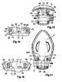
- Figures 15 and 16 refer to the lid position (6) closed; in this position, the spring (7) pushes in the direction of the arrow, so that the posterior extension (21) of the posterior prominence (15) remains fitted into the first notch (26) of the posterior hole (25) of the posterior bearing (23) and the wall rear (17) of the anterior prominence (14) abuts against the posterior partition (29).
- Figures 17 and 18 are refer to the open lid position (6); this position is obtained by pressing the button (8) in the direction indicated by the arrow, which compresses the spring (7) until said posterior prominence (15) of the first notch (26) and the lid (6) opens driven by the radial extension of said spring compression and torsion (7).
- this operation requires only simple, fast actions and convenient supports that automatically determine the stable positions of closure and opening, allowing to release both hands to operate the key and offering a reliable closure independent of the action of the spring (7).
- the first indentation (18) of the orifice (12) on the side posterior (10) of the cavity (11) of the body (1) is intended to allow the passage of the previous prominences (14) and posterior (15).
- the second notch (19) of said orifice (12) and the second indentation (27) of the posterior hole (25) of the rear bearing (23) of the cover (6) serve to facilitate the initial assembly, the shaft (5) being rotated 90 ° in the opposite direction to that of the opening of the cover (6) for said prominences (14, 15) do not come in contact with the anterior partitions (28) and posterior (29) of it, except the elastic jump cited between the anterior prominence (14) and the septum previous (28).
- the tree (5) includes anti-rotation means consisting of a button (8) with extended configuration teardrop that stands and plays operationally in a cavity (31) formed in the blocking body (1).
- shaft (5) is hollow and said compression spring and twist (7) is installed inside the hollow shaft (5), where is always its anchored end and where its other end remains applied to the part of the base (13) surrounded by the crown molded therein.
Landscapes
- Engineering & Computer Science (AREA)
- Mechanical Engineering (AREA)
- Pivots And Pivotal Connections (AREA)
Applications Claiming Priority (2)
| Application Number | Priority Date | Filing Date | Title |
|---|---|---|---|
| ES200400216U | 2004-02-02 | ||
| ES200400216U ES1056569Y (es) | 2004-02-02 | 2004-02-02 | Dispositivo de candado de bloqueo rotatorio para disco de freno de motocicletas. |
Publications (2)
| Publication Number | Publication Date |
|---|---|
| EP1559643A1 true EP1559643A1 (de) | 2005-08-03 |
| EP1559643B1 EP1559643B1 (de) | 2006-06-07 |
Family
ID=32050394
Family Applications (1)
| Application Number | Title | Priority Date | Filing Date |
|---|---|---|---|
| EP05290230A Expired - Lifetime EP1559643B1 (de) | 2004-02-02 | 2005-02-02 | Scheibenbremsenschloss für Motorräder |
Country Status (2)
| Country | Link |
|---|---|
| EP (1) | EP1559643B1 (de) |
| ES (1) | ES1056569Y (de) |
Citations (5)
| Publication number | Priority date | Publication date | Assignee | Title |
|---|---|---|---|---|
| FR2702728A1 (fr) * | 1993-03-19 | 1994-09-23 | Carreras Jacques | Antivol perfectionné pour motocyclette équipée d'un disque de frein ajouré. |
| FR2705077A1 (fr) * | 1993-05-12 | 1994-11-18 | Jouvin Pleintube Jl | Dispositif antivol pour motocycle. |
| US5916279A (en) * | 1997-12-11 | 1999-06-29 | Shieh; Jin-Ren | Motorcycle disk brake lock |
| US6553793B1 (en) * | 2002-05-16 | 2003-04-29 | Tian-Yuan Chen | Motorcycle disc brake lock |
| US20030188938A1 (en) * | 2000-05-26 | 2003-10-09 | Chiyuan Li | Self -guided locking device for a motorcycle disk brake piece |
-
2004
- 2004-02-02 ES ES200400216U patent/ES1056569Y/es not_active Expired - Fee Related
-
2005
- 2005-02-02 EP EP05290230A patent/EP1559643B1/de not_active Expired - Lifetime
Patent Citations (5)
| Publication number | Priority date | Publication date | Assignee | Title |
|---|---|---|---|---|
| FR2702728A1 (fr) * | 1993-03-19 | 1994-09-23 | Carreras Jacques | Antivol perfectionné pour motocyclette équipée d'un disque de frein ajouré. |
| FR2705077A1 (fr) * | 1993-05-12 | 1994-11-18 | Jouvin Pleintube Jl | Dispositif antivol pour motocycle. |
| US5916279A (en) * | 1997-12-11 | 1999-06-29 | Shieh; Jin-Ren | Motorcycle disk brake lock |
| US20030188938A1 (en) * | 2000-05-26 | 2003-10-09 | Chiyuan Li | Self -guided locking device for a motorcycle disk brake piece |
| US6553793B1 (en) * | 2002-05-16 | 2003-04-29 | Tian-Yuan Chen | Motorcycle disc brake lock |
Also Published As
| Publication number | Publication date |
|---|---|
| EP1559643B1 (de) | 2006-06-07 |
| ES1056569U (es) | 2004-04-01 |
| ES1056569Y (es) | 2004-07-16 |
Similar Documents
| Publication | Publication Date | Title |
|---|---|---|
| EP1169955B1 (de) | Deckelverriegelungsvorrichtung | |
| FR2789717A1 (fr) | Serrure en trois parties, pour ouvrant de vehicule automobile | |
| FR2849088A1 (fr) | Cadenas | |
| EP1030012B1 (de) | Kraftfahrzeugschloss mit energiespeichernder Entriegelungsvorrichtung | |
| CA1265693A (fr) | Dispositif de verrouillage de tampon de regard de chaussee | |
| EP1188889A1 (de) | Kraftfahrzeug mit voneinander unabhängigen Schwenk- und Schiebetüren | |
| EP3464762A1 (de) | Vorrichtung zum verriegeln und entriegeln einer schachtabdeckung auf einem rahmen mittels eines schlüssels mit der option einer automatischen schlüssellosen verriegelung dieser schachtabdeckung auf dem rahmen | |
| FR2686118A1 (fr) | Mecanisme de serrure pour porte ou abattant. | |
| EP1559643B1 (de) | Scheibenbremsenschloss für Motorräder | |
| EP2565353B1 (de) | Vorrichtung zum Verriegeln und Entriegeln mit Hilfe eines Schlüssels einer Abdeckung auf einem Rahmen mit integrierter Verschlusseinlage eines Öffnungselements der Abdeckung für das Einführen des Schlüssels | |
| EP3523488B1 (de) | Betätigungsvorrichtung für spülkasten mit drehwähler | |
| EP4108856B1 (de) | Steuerungsvorrichtung eines verriegelungs-/entriegelungssystems eines öffnungsflügels und entsprechender tür-/fensterrahmen | |
| FR2478719A1 (fr) | Serrure a pene dormant transversal a verrouillage automatique | |
| FR2789718A1 (fr) | Serrure a condamnation enfant, pour ouvrant de vehicule automobile | |
| FR2919364A3 (fr) | Dispositif d'embrayage avec fonction anti-panique pour verrous electromecaniques | |
| FR2583452A1 (fr) | Boitier de cremone a plaquer avec condamnation. | |
| FR2730755A1 (fr) | Organe de manoeuvre notamment poignee equipe de moyens pour rendre son utilisation selective constituant une securite pour enfant | |
| EP0237421B1 (de) | Verschluss, insbesondere für Kühlkammertür | |
| CH294220A (fr) | Serrure à entailler. | |
| FR2766859A1 (fr) | Serrure de loquet | |
| FR2629856A1 (de) | ||
| FR2858001A1 (fr) | Serrure a pene dormant, manoeuvrable par bouton ou clef | |
| FR2799350A1 (fr) | Mecanisme de serrure, serrure et bagage equipes d'un tel mecanisme | |
| FR2802565A1 (fr) | Boitier median de serrure antipanique multipoint reversible, et serrure antipanique equipee d'un tel boitier | |
| FR2671126A1 (fr) | Embrayage de securite pour poignee de portes ou de fenetres. |
Legal Events
| Date | Code | Title | Description |
|---|---|---|---|
| PUAI | Public reference made under article 153(3) epc to a published international application that has entered the european phase |
Free format text: ORIGINAL CODE: 0009012 |
|
| AK | Designated contracting states |
Kind code of ref document: A1 Designated state(s): AT BE BG CH CY CZ DE DK EE ES FI FR GB GR HU IE IS IT LI LT LU MC NL PL PT RO SE SI SK TR |
|
| AX | Request for extension of the european patent |
Extension state: AL BA HR LV MK YU |
|
| 17P | Request for examination filed |
Effective date: 20050805 |
|
| GRAP | Despatch of communication of intention to grant a patent |
Free format text: ORIGINAL CODE: EPIDOSNIGR1 |
|
| RIN1 | Information on inventor provided before grant (corrected) |
Inventor name: MUERZA, ALFREDOC/O LUMA INDUSTRIES S.A. |
|
| GRAS | Grant fee paid |
Free format text: ORIGINAL CODE: EPIDOSNIGR3 |
|
| AKX | Designation fees paid |
Designated state(s): BE FR GR IT NL |
|
| GRAA | (expected) grant |
Free format text: ORIGINAL CODE: 0009210 |
|
| REG | Reference to a national code |
Ref country code: DE Ref legal event code: 8566 |
|
| AK | Designated contracting states |
Kind code of ref document: B1 Designated state(s): BE FR GR IT NL |
|
| PLBE | No opposition filed within time limit |
Free format text: ORIGINAL CODE: 0009261 |
|
| STAA | Information on the status of an ep patent application or granted ep patent |
Free format text: STATUS: NO OPPOSITION FILED WITHIN TIME LIMIT |
|
| 26N | No opposition filed |
Effective date: 20070308 |
|
| PG25 | Lapsed in a contracting state [announced via postgrant information from national office to epo] |
Ref country code: GR Free format text: LAPSE BECAUSE OF FAILURE TO SUBMIT A TRANSLATION OF THE DESCRIPTION OR TO PAY THE FEE WITHIN THE PRESCRIBED TIME-LIMIT Effective date: 20060908 |
|
| PGFP | Annual fee paid to national office [announced via postgrant information from national office to epo] |
Ref country code: NL Payment date: 20090220 Year of fee payment: 5 |
|
| PGFP | Annual fee paid to national office [announced via postgrant information from national office to epo] |
Ref country code: BE Payment date: 20090102 Year of fee payment: 5 |
|
| BERE | Be: lapsed |
Owner name: LUMA INDUSTRIAS, S.A. Effective date: 20100228 |
|
| REG | Reference to a national code |
Ref country code: NL Ref legal event code: V1 Effective date: 20100901 |
|
| PG25 | Lapsed in a contracting state [announced via postgrant information from national office to epo] |
Ref country code: NL Free format text: LAPSE BECAUSE OF NON-PAYMENT OF DUE FEES Effective date: 20100901 |
|
| PG25 | Lapsed in a contracting state [announced via postgrant information from national office to epo] |
Ref country code: BE Free format text: LAPSE BECAUSE OF NON-PAYMENT OF DUE FEES Effective date: 20100228 |
|
| PGFP | Annual fee paid to national office [announced via postgrant information from national office to epo] |
Ref country code: IT Payment date: 20080228 Year of fee payment: 4 |
|
| PGFP | Annual fee paid to national office [announced via postgrant information from national office to epo] |
Ref country code: FR Payment date: 20120221 Year of fee payment: 8 |
|
| REG | Reference to a national code |
Ref country code: FR Ref legal event code: ST Effective date: 20131031 |
|
| PG25 | Lapsed in a contracting state [announced via postgrant information from national office to epo] |
Ref country code: FR Free format text: LAPSE BECAUSE OF NON-PAYMENT OF DUE FEES Effective date: 20130228 |