EP1559643A1 - Disk brake lock for motorcycles - Google Patents
Disk brake lock for motorcycles Download PDFInfo
- Publication number
- EP1559643A1 EP1559643A1 EP05290230A EP05290230A EP1559643A1 EP 1559643 A1 EP1559643 A1 EP 1559643A1 EP 05290230 A EP05290230 A EP 05290230A EP 05290230 A EP05290230 A EP 05290230A EP 1559643 A1 EP1559643 A1 EP 1559643A1
- Authority
- EP
- European Patent Office
- Prior art keywords
- posterior
- anterior
- shaft
- lid
- prominence
- Prior art date
- Legal status (The legal status is an assumption and is not a legal conclusion. Google has not performed a legal analysis and makes no representation as to the accuracy of the status listed.)
- Granted
Links
- 230000006835 compression Effects 0.000 claims abstract description 17
- 238000007906 compression Methods 0.000 claims abstract description 17
- 230000000994 depressogenic effect Effects 0.000 claims description 13
- 238000007373 indentation Methods 0.000 claims description 13
- 238000005192 partition Methods 0.000 claims description 13
- 230000000903 blocking effect Effects 0.000 claims description 10
- 238000003780 insertion Methods 0.000 claims description 9
- 230000037431 insertion Effects 0.000 claims description 9
- 230000000284 resting effect Effects 0.000 claims description 2
- 208000031968 Cadaver Diseases 0.000 description 6
- 240000008042 Zea mays Species 0.000 description 1
- -1 dirt Substances 0.000 description 1
- 239000000428 dust Substances 0.000 description 1
- 230000000717 retained effect Effects 0.000 description 1
- XLYOFNOQVPJJNP-UHFFFAOYSA-N water Substances O XLYOFNOQVPJJNP-UHFFFAOYSA-N 0.000 description 1
Images

Classifications
-
- B—PERFORMING OPERATIONS; TRANSPORTING
- B62—LAND VEHICLES FOR TRAVELLING OTHERWISE THAN ON RAILS
- B62H—CYCLE STANDS; SUPPORTS OR HOLDERS FOR PARKING OR STORING CYCLES; APPLIANCES PREVENTING OR INDICATING UNAUTHORIZED USE OR THEFT OF CYCLES; LOCKS INTEGRAL WITH CYCLES; DEVICES FOR LEARNING TO RIDE CYCLES
- B62H5/00—Appliances preventing or indicating unauthorised use or theft of cycles; Locks integral with cycles
- B62H5/14—Appliances preventing or indicating unauthorised use or theft of cycles; Locks integral with cycles preventing wheel rotation
- B62H5/18—Appliances preventing or indicating unauthorised use or theft of cycles; Locks integral with cycles preventing wheel rotation acting on a braking device
Definitions
- the present invention relates to a device for padlock specially designed to prevent the rotation of the wheel of a motorcycle, which is placed in the disc of brake of it so that, trying to do turn the wheel, it comes up against elements of the frame.
- this type of padlock consists of a blocking body which is provided with a groove for the insertion of the brake disc and in which, transversely to said disk, is likely to penetrate a lock that passes through one of the usual holes brake disc and is operated by a mechanism of key lock that is installed within the lock body and who has cover means to cover access for the key when not acting on the lock.
- the device now proposed has a special constitution which includes a shaft, a folding lid and a spring helical compression and torsion; the tree having a insertion fitting with axial sliding in the body blocking and, in relation to the meaning of that insertion, that tree has a free anterior end as well as a posterior end where is incorporated an axial button, and this assembly of the tree is carried out between two sides, anterior and posterior, of a cavity dug in the body, where the shaft has an axial sliding capacity between each of the positions depressed and not depressed, said side posterior having an orifice that has a sliding fit relative to the contour of the tree and whose side prior to a base with anti-rotatory means reciprocally other means existing in the said anterior end of said sliding shaft which has, in its axial alignment, previous prominences and posterior such as: anterior prominence has a front ramp as well as a rear wall and is likely to go through any of two indentations, a first and a second, diametrically opposite said orifice; and prominence
- the folding lid is rotatably mounted in sliding shaft with capacity to adopt respective positions of closure and opening in which the access of the key to the lock covers or discovers itself, these positions being distant from rotate one quarter of a turn between them and corresponding to said positions not depressed and depressed axial button.
- the folding lid has two bearings, front and back, which are backed respectively to said sides of said body cavity and who each have a hole, anterior and posterior, the posterior hole with two indentations, a first and a second, which in the closed position of the lid foldable respectively remain aligned with the notches in the hole on the posterior side of the cavity, whereas the first notch of said hole posterior and the first notch of the orifice on the side posterior remain aligned with the prominences anterior and posterior of the tree.
- the folding lid has two partitions, anterior and posterior, which are placed radially relative to the shaft so that, in position of open lid, posterior prominence remains supported against the posterior bearing and, in the lid position closed, this posterior prominence remains in the first indentation of the posterior hole while the anterior prominence remains applied against the face of the posterior partition looking towards the anterior partition.
- Said helical spring of compression and twisting has an end anchored in said shaft and its other end is applied in said base on the anterior side of said cavity and, at this place, it has a radial extension that remains applied inside the lid and pushes into the sense of said opening position thereof, and which remains confined between the said previous level and the said front wall of the lid.
- This simple composition based on three pieces unique offers simple automatic operation and dresser.
- the closing position of the folding lid is held against the elastic torsion pulse of the compression spring and torsion because the prominence posterior remains through the first notch of the posterior hole of the posterior bearing and the shaft can not turn; in this position the tree, and by therefore the button, can not go out because the anterior prominence remains applied against the septum posterior of the lid by the extension action elastic spring; the fact that this prominence front is located in this side of the partition earlier is due to the fact that during the initial there was an elastic jump of prominence anterior to the anterior septum, with a maneuver that is favored by the ramp before this anterior prominence.
- the opening position is obtained by simply pressing the button, then, the posterior prominence comes out of the first notch and the axial extension of the compression and torsion spring releases a stored torsional elastic energy that automatically causes the lid to open; in releasing the button the posterior prominence remains leaning against the posterior bearing and maintains the depressed position of the button.
- a mode of execution preferred embodiment of the invention corresponding to a device rotary lock for motorcycle brake disc which responds to a general composition that includes a blocking body (1) having a groove (2) intended for the insertion of the brake disc (3) and into which, transversely to this one, is likely to to enter a bolt (4) through one of the holes said brake disc (3) and is actuated by a key lock mechanism that is installed within the blocking body (1) and having passable means coverage of access for the key, when one does not act on the lock.
- this device consists of a shaft (5), a cover foldable (6) as well as a helical spring of compression (7).
- Said shaft (5) has a mounting by insertion with axial sliding and rotary locking in the blocking body (1) and, in relation to the direction of this insertion, this shaft (5) has one end anterior free and a posterior end where is incorporated an axial button (8).
- the assembly of the shaft (5) is realized between two sides, anterior (9) and posterior (10), a cavity (11) hollowed out in the body (1), where the shaft (5) has an axial sliding capacity between each of the positions depressed and not depressed, the posterior (10) of said cavity having an orifice (12) which has a sliding fit relative to the contour of the shaft (5) and whose front side (9) has a base (13) for said anterior end of a said shaft slider (5) which has prominences, anterior (14) and posterior (15) axially aligned and such that the anterior prominence (14) has a front ramp (16) as well as a rear wall (17) and is capable of widely go through any of two indentations, a first (18) and a second (19), diametrically opposite said orifice (12); and the posterior prominence (15) is likely to cross said first (18) and second (19) indentations, and has an anterior face (20) and an extension posterior (21) which is scaled down and with adjustment passing relative to said indentations (18, 19).
- Said folding lid (6) is rotatably mounted in the sliding shaft (5) with the ability to adopt the respective positions of closure and opening in which access of the key to the lock is covered or discovered. These positions are far away rotating a quarter turn between them and correspond at said positions not depressed and depressed axial (8), and the folding lid (6) has two bearings, anterior (22) and posterior (23), which are backed respectively to said sides (9 and 10) of the cavity (11) of the body (1) and which each have a hole, anterior (24) and posterior (25), the posterior hole (25) having two indentations, a first (26) and a second (27), which in the closed position of the lid foldable (6) remain aligned with the notches (18, 19) of the orifice (12) on the posterior side (10) of said cavity (11), while the first notch (18) and the first notch (26) remain aligned with the anterior prominences (14) and posterior (15) of the shaft (5).
- the folding lid (6) has two partitions, anterior (28) and posterior (29), which are placed radially with respect to the shaft (5) so that, in open lid position (6), the prominence posterior (15) remains resting against the posterior bearing (23) and, in the closed lid position (6), this posterior prominence (15) remains through the first indentation (26) of the posterior hole (25) while the anterior prominence (14) remains applied against the face of the posterior partition (29) which looks direction of the anterior partition (28), and said spring helical compression and torsion (7) has a end anchored in said shaft (5) and its other end is applied in said base (13) on the anterior (9) of said cavity (11), where it has a radial extension (30) which remains applied inside of the cover (6) pushing said open position of it and remaining confined between said previous level (22) and said anterior partition (28) of the lid (6).
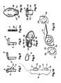
- composition of the blocking body (1) is illustrated in Figures 1 to 4; that of the shaft (5) with button (8), by means of Figures 5 and 7 to 10; that of the lid (6), by means of FIGS. 6 and 11 to 13, and that of the spring helical compression and torsion (7) by means of Figure 14.
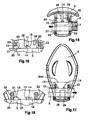
- Figures 15 and 16 refer to the lid position (6) closed; in this position, the spring (7) pushes in the direction of the arrow, so that the posterior extension (21) of the posterior prominence (15) remains fitted into the first notch (26) of the posterior hole (25) of the posterior bearing (23) and the wall rear (17) of the anterior prominence (14) abuts against the posterior partition (29).
- Figures 17 and 18 are refer to the open lid position (6); this position is obtained by pressing the button (8) in the direction indicated by the arrow, which compresses the spring (7) until said posterior prominence (15) of the first notch (26) and the lid (6) opens driven by the radial extension of said spring compression and torsion (7).
- this operation requires only simple, fast actions and convenient supports that automatically determine the stable positions of closure and opening, allowing to release both hands to operate the key and offering a reliable closure independent of the action of the spring (7).
- the first indentation (18) of the orifice (12) on the side posterior (10) of the cavity (11) of the body (1) is intended to allow the passage of the previous prominences (14) and posterior (15).
- the second notch (19) of said orifice (12) and the second indentation (27) of the posterior hole (25) of the rear bearing (23) of the cover (6) serve to facilitate the initial assembly, the shaft (5) being rotated 90 ° in the opposite direction to that of the opening of the cover (6) for said prominences (14, 15) do not come in contact with the anterior partitions (28) and posterior (29) of it, except the elastic jump cited between the anterior prominence (14) and the septum previous (28).
- the tree (5) includes anti-rotation means consisting of a button (8) with extended configuration teardrop that stands and plays operationally in a cavity (31) formed in the blocking body (1).
- shaft (5) is hollow and said compression spring and twist (7) is installed inside the hollow shaft (5), where is always its anchored end and where its other end remains applied to the part of the base (13) surrounded by the crown molded therein.
Landscapes
- Engineering & Computer Science (AREA)
- Mechanical Engineering (AREA)
- Pivots And Pivotal Connections (AREA)
Abstract
Description
La présente Invention concerne un dispositif de cadenas spécialement destiné à empêcher la rotation de la roue d'une motocyclette, qui se place dans le disque de frein de celle-ci de sorte que, en essayant de faire tourner la roue, il vienne buter contre des éléments du châssis.The present invention relates to a device for padlock specially designed to prevent the rotation of the wheel of a motorcycle, which is placed in the disc of brake of it so that, trying to do turn the wheel, it comes up against elements of the frame.
En général, ce type de cadenas est constitué d'un corps de blocage qui est doté d'une rainure destinée à l'insertion du disque de frein et dans laquelle, transversalement audit disque, est susceptible de pénétrer un verrou qui traverse l'un des trous habituels dudit disque de frein et est actionné par un mécanisme de serrure à clé qui est installé au sein du corps de blocage et qui possède des moyens de couverture pour couvrir l'accès pour la clé lorsqu'on n'agit pas sur la serrure.In general, this type of padlock consists of a blocking body which is provided with a groove for the insertion of the brake disc and in which, transversely to said disk, is likely to penetrate a lock that passes through one of the usual holes brake disc and is operated by a mechanism of key lock that is installed within the lock body and who has cover means to cover access for the key when not acting on the lock.
Dans ce domaine et répondant à cette composition générale, on connaít des dispositifs dans lesquels les moyens de couverture de l'accès de la clé à la serrure (évitant l'entrée de la poussière, de la saleté, de l'eau) soit sont de constitution et d'actionnement complexes, soit s'avèrent incommodes et peu pratiques. Par conséquent, pour actionner certains moyens de couverture, comme par exemple un couvercle rabattable, il faut actuellement avoir dans une main le cadenas et avec l'autre main, généralement occupée à tenir la clé du cadenas, saisir le couvercle et le relever (l'ouvrir) jusqu'à obtenir une position dans laquelle il tienne tout seule ; on peut alors procéder à la manoeuvre de fermeture au moyen de la clé qui laisse le cadenas installé de manière opérationnelle ; dans ce cas-là, la fermeture habituelle du couvercle consiste seulement en une butée d'encastrement sans qu'il n'existe une condamnation mécanique qui bloque l'état de fermeture.In this field and responding to this composition In general, there are known devices in which means of covering the access of the key to the lock (avoiding the entry of dust, dirt, water) either have complex constitution and actuation, either prove inconvenient and impractical. By therefore, to operate certain means of coverage, like a folding lid, you have to currently have in one hand the padlock and with the other hand, usually busy holding the key of the padlock, grasp the lid and lift it up (open it) to get a position in which he holds everything alone ; we can then proceed to the closing maneuver by means of the key that leaves the lock installed operational way; in this case, the closure usual cover only consists of a stop recess without a conviction mechanical blocking the closing state.
Face à cet état de chose, le dispositif désormais proposé a une constitution particulière qui comprend un arbre, un couvercle rabattable ainsi qu'un ressort hélicoïdal de compression et de torsion ; l'arbre ayant un montage par insertion avec glissement axial dans le corps de blocage et, par rapport au sens de cette insertion, cet arbre possède une extrémité antérieure libre ainsi qu'une extrémité postérieure où est incorporé un bouton axial, et ce montage de l'arbre se réalise entre deux côtés, antérieur et postérieur, d'une cavité creusée dans le corps, où l'arbre a une capacité de glissement axial entre chacune des positions enfoncée et non enfoncée, ledit côté postérieur ayant un orifice qui a un ajustement coulissant par rapport au contour de l'arbre et dont le côté antérieur a une embase avec des moyens anti-rotatoires réciproques d'autres moyens existants dans ladite extrémité antérieure dudit arbre coulissant qui a, dans son alignement axial, des proéminences antérieure et postérieure telles que : la proéminence antérieure présente une rampe avant ainsi qu'une paroi arrière et est susceptible de passer largement par n'importe laquelle de deux échancrures, une première et une seconde, diamétralement opposées audit orifice ; et la proéminence postérieure est susceptible de traverser lesdites , première et seconde échancrures, et présente une face antérieure ainsi qu'une extension postérieure qui est échelonnée en diminution et avec ajustement passant par rapport auxdites échancrures. Le couvercle rabattable est monté rotatif dans l'arbre coulissant avec la capacité d'adopter des positions respectives de fermeture et d'ouverture dans lesquelles l'accès de la clé à la serrure se couvre ou se découvre, ces positions étant éloignées de manière rotative d'un quart de tour entre elles et correspondant auxdites positions non enfoncée et enfoncée du bouton axial. Le couvercle rabattable possède deux paliers, antérieur et postérieur, qui sont adossés respectivement auxdits côtés de ladite cavité du corps et qui possèdent chacun un trou, antérieur et postérieur, le trou postérieur présentant deux échancrures, une première et une seconde, qui en position de fermeture du couvercle rabattable restent respectivement alignées avec les échancrures de l'orifice du côté postérieur de ladite cavité, alors que la première échancrure dudit trou postérieur et la première échancrure de l'orifice du côté postérieur restent alignées avec les proéminences antérieure et postérieure de l'arbre. Entre lesdits paliers le couvercle rabattable possède deux cloisons, antérieure et postérieure, qui sont placées radialement par rapport à l'arbre de sorte que, en position de couvercle ouvert, la proéminence postérieure reste appuyée contre le palier postérieur et, en position de couvercle fermé, cette proéminence postérieure reste dans la première échancrure du trou postérieur alors que la proéminence antérieure reste appliquée contre la face de la cloison postérieure qui regarde en direction de la cloison antérieure. Ledit ressort hélicoïdal de compression et de torsion a une extrémité ancrée dans ledit arbre et son autre extrémité est appliquée dans ladite embase du côté antérieur de ladite cavité et, à cet endroit, il présente une extension radiale qui reste appliquée à l'intérieur du couvercle et pousse dans le sens de ladite position d'ouverture de celui-ci, et qui reste confinée entre ledit palier antérieur et ladite cloison antérieure du couvercle.Faced with this state of affairs, the device now proposed has a special constitution which includes a shaft, a folding lid and a spring helical compression and torsion; the tree having a insertion fitting with axial sliding in the body blocking and, in relation to the meaning of that insertion, that tree has a free anterior end as well as a posterior end where is incorporated an axial button, and this assembly of the tree is carried out between two sides, anterior and posterior, of a cavity dug in the body, where the shaft has an axial sliding capacity between each of the positions depressed and not depressed, said side posterior having an orifice that has a sliding fit relative to the contour of the tree and whose side prior to a base with anti-rotatory means reciprocally other means existing in the said anterior end of said sliding shaft which has, in its axial alignment, previous prominences and posterior such as: anterior prominence has a front ramp as well as a rear wall and is likely to go through any of two indentations, a first and a second, diametrically opposite said orifice; and prominence posterior is likely to cross the said, first and second notches, and has a face previous as well as a posterior extension that is staggered down and with adjustment going through referred to said indentations. The folding lid is rotatably mounted in sliding shaft with capacity to adopt respective positions of closure and opening in which the access of the key to the lock covers or discovers itself, these positions being distant from rotate one quarter of a turn between them and corresponding to said positions not depressed and depressed axial button. The folding lid has two bearings, front and back, which are backed respectively to said sides of said body cavity and who each have a hole, anterior and posterior, the posterior hole with two indentations, a first and a second, which in the closed position of the lid foldable respectively remain aligned with the notches in the hole on the posterior side of the cavity, whereas the first notch of said hole posterior and the first notch of the orifice on the side posterior remain aligned with the prominences anterior and posterior of the tree. Between said bearings the folding lid has two partitions, anterior and posterior, which are placed radially relative to the shaft so that, in position of open lid, posterior prominence remains supported against the posterior bearing and, in the lid position closed, this posterior prominence remains in the first indentation of the posterior hole while the anterior prominence remains applied against the face of the posterior partition looking towards the anterior partition. Said helical spring of compression and twisting has an end anchored in said shaft and its other end is applied in said base on the anterior side of said cavity and, at this place, it has a radial extension that remains applied inside the lid and pushes into the sense of said opening position thereof, and which remains confined between the said previous level and the said front wall of the lid.
Cette composition simple à base de trois pièces uniques offre un fonctionnement automatique simple et commode. La position de fermeture du couvercle rabattable est retenue contre l'impulsion de torsion élastique du ressort de compression et de torsion, car la proéminence postérieure reste au travers de la première échancrure du trou postérieur du palier postérieur et l'arbre ne peut pas tourner ; dans cette position l'arbre, et par conséquent le bouton, ne peut pas sortir parce que la proéminence antérieure reste appliquée contre la cloison postérieure du couvercle par l'action d'extension élastique du ressort ; le fait que cette proéminence antérieure soit située dans ce côté de la cloison antérieure est dû au fait qu'au cours du montage initial il s'est produit un saut élastique de la proéminence antérieure par rapport à la cloison antérieure, avec une manoeuvre qui est favorisée par la rampe avant de cette proéminence antérieure. La position d'ouverture est obtenue en appuyant simplement sur le bouton, alors, la proéminence postérieure sort de la première échancrure et l'extension axiale du ressort de compression et de torsion libère une énergie élastique de torsion stockée qui entraíne automatiquement l'ouverture du couvercle ; en relâchant le bouton la proéminence postérieure reste appuyée contre le palier postérieur et maintient la position enfoncée du bouton.This simple composition based on three pieces unique offers simple automatic operation and dresser. The closing position of the folding lid is held against the elastic torsion pulse of the compression spring and torsion because the prominence posterior remains through the first notch of the posterior hole of the posterior bearing and the shaft can not turn; in this position the tree, and by therefore the button, can not go out because the anterior prominence remains applied against the septum posterior of the lid by the extension action elastic spring; the fact that this prominence front is located in this side of the partition earlier is due to the fact that during the initial there was an elastic jump of prominence anterior to the anterior septum, with a maneuver that is favored by the ramp before this anterior prominence. The opening position is obtained by simply pressing the button, then, the posterior prominence comes out of the first notch and the axial extension of the compression and torsion spring releases a stored torsional elastic energy that automatically causes the lid to open; in releasing the button the posterior prominence remains leaning against the posterior bearing and maintains the depressed position of the button.
On notera que ce fonctionnement nécessite uniquement une pression réalisée avec une main de manière facile et commode pour obtenir l'ouverture du couvercle et accéder librement à la serrure du cadenas ; et pour fermer il suffit également d'actionner le couvercle jusqu'à ce qu'il atteigne sa position de fermeture dans laquelle il reste automatiquement retenu.Note that this operation only requires a pressure made with one hand in an easy way and convenient to open the lid and access freely at the padlock lock; and to close it It is also sufficient to operate the lid until reaches its closing position in which it remains automatically retained.
Ces particularités de la présente invention, ainsi que d'autres, seront exposées plus en détail dans la description suivante. These features of the present invention, as well as others will be explained in more detail in the following description.
Afin de mieux comprendre la nature de la présente
invention, on a représenté sur les dessins ci-joints, une
forme préférée de réalisation industrielle, qui tient lieu
d'exemple simplement illustratif et non restrictif.
Dans ces figures sont indiquées les références
suivantes :
Concernant les dessins et références susmentionnés, est illustré dans les plans ci-joints un mode d'exécution préférentiel de l'invention correspondant à un dispositif de blocage rotatoire pour disque de frein de motocyclettes qui répond à une composition générale qui comprend un corps de blocage (1) qui est doté d'une rainure (2) destinée à l'insertion du disque de frein (3) et dans laquelle, transversalement à celui-ci, est susceptible de pénétrer un verrou (4) qu'il traverse par l'un des trous habituels dudit disque de frein (3) et est actionné par un mécanisme de serrure de clé qui est installé au sein du corps de blocage (1) et qui possède des moyens praticables de couverture de l'accès pour la clé, lorsqu'on n'agit pas sur la serrure.Concerning the aforementioned drawings and references, is illustrated in the attached plans a mode of execution preferred embodiment of the invention corresponding to a device rotary lock for motorcycle brake disc which responds to a general composition that includes a blocking body (1) having a groove (2) intended for the insertion of the brake disc (3) and into which, transversely to this one, is likely to to enter a bolt (4) through one of the holes said brake disc (3) and is actuated by a key lock mechanism that is installed within the blocking body (1) and having passable means coverage of access for the key, when one does not act on the lock.
Selon la conception particulière de l'invention, ce dispositif se compose d'un arbre (5), d'un couvercle rabattable (6) ainsi que d'un ressort hélicoïdal de compression (7). Ledit arbre (5) a un montage par insertion avec glissement axial et verrouillage rotatoire dans le corps de blocage (1) et, par rapport au sens de cette insertion, cet arbre (5) possède une extrémité antérieure libre et une extrémité postérieure où est incorporé un bouton axial (8). Le montage de l'arbre (5) se réalise entre deux côtés, antérieur (9) et postérieur (10), d'une cavité (11) creusée dans le corps (1), où l'arbre (5) a une capacité de glissement axial entre chacune des positions enfoncée et non enfoncée, le côté postérieur (10) de ladite cavité ayant un orifice (12) qui a un ajustement coulissant par rapport au contour de l'arbre (5) et dont le côté antérieur (9) a une embase (13) pour ladite extrémité antérieure d'un dit arbre coulissant (5) qui a des proéminences, antérieure (14) et postérieure (15), alignées axialement et telles que la proéminence antérieure (14) présente une rampe avant (16) ainsi qu'une paroi arrière (17) et est susceptible de passer largement par n'importe laquelle de deux échancrures, une première (18) et une seconde (19), diamétralement opposées audit orifice (12); et la proéminence postérieure (15) est susceptible de traverser lesdites première (18) et seconde (19) échancrures, et présente une face antérieure (20) ainsi qu'une extension postérieure (21) qui est échelonnée en diminution et avec ajustement passant par rapport auxdites échancrures (18, 19). Ledit couvercle rabattable (6) est monté rotatif dans l'arbre coulissant (5) avec la capacité d'adopter les positions respectives de fermeture et d'ouverture dans lesquelles l'accès de la clé de la serrure est couvert ou découvert. Ces positions sont éloignées de manière rotative d'un quart de tour entre elles et correspondent auxdites positions non enfoncée et enfoncée du bouton axial (8), et le couvercle rabattable (6) possède deux paliers, antérieur (22) et postérieur (23), qui sont adossés respectivement auxdits côtés (9 et 10) de la cavité (11) du corps (1) et qui possèdent chacun un trou, antérieur (24) et postérieur (25), le trou postérieur (25) possédant deux échancrures, une première (26) et une seconde (27), qui en position de fermeture du couvercle rabattable (6) restent respectivement alignées avec les échancrures (18, 19) de l'orifice (12) du côté postérieur (10) de ladite cavité (11), alors que la première échancrure (18) et la première échancrure (26) restent alignées avec les proéminences antérieure (14) et postérieure (15) de l'arbre (5). Entre lesdits paliers (22, 23) le couvercle rabattable (6) possède deux cloisons, antérieure (28) et postérieure (29), qui sont placées radialement par rapport à l'arbre (5) de sorte que, en position de couvercle (6) ouvert, la proéminence postérieure (15) reste appuyée contre le palier postérieur (23) et, en position de couvercle (6) fermé, cette proéminence postérieure (15) reste au travers de la première échancrure (26) du trou postérieur (25) alors que la proéminence antérieure (14) reste appliquée contre la face de la cloison postérieure (29) qui regarde en direction de la cloison antérieure (28), et ledit ressort hélicoïdal de compression et de torsion (7) a une extrémité ancrée dans ledit arbre (5) et son autre extrémité est appliquée dans ladite embase (13) du côté antérieur (9) de ladite cavité (11), où elle présente une extension radiale (30) qui reste appliquée à l'intérieur du couvercle (6) poussant ladite position d'ouverture de celui-ci et restant confinée entre ledit palier antérieur (22) et ladite cloison antérieure (28) du couvercle (6). La composition du corps de blocage (1) est illustrée dans les figures 1 à 4 ; celle de l'arbre (5) avec bouton (8), au moyen des figures 5 et 7 à 10 ; celle du couvercle (6), au moyen des figures 6 et 11 à 13, et celle du ressort hélicoïdal de compression et de torsion (7), au moyen de la figure 14.According to the particular design of the invention, this device consists of a shaft (5), a cover foldable (6) as well as a helical spring of compression (7). Said shaft (5) has a mounting by insertion with axial sliding and rotary locking in the blocking body (1) and, in relation to the direction of this insertion, this shaft (5) has one end anterior free and a posterior end where is incorporated an axial button (8). The assembly of the shaft (5) is realized between two sides, anterior (9) and posterior (10), a cavity (11) hollowed out in the body (1), where the shaft (5) has an axial sliding capacity between each of the positions depressed and not depressed, the posterior (10) of said cavity having an orifice (12) which has a sliding fit relative to the contour of the shaft (5) and whose front side (9) has a base (13) for said anterior end of a said shaft slider (5) which has prominences, anterior (14) and posterior (15) axially aligned and such that the anterior prominence (14) has a front ramp (16) as well as a rear wall (17) and is capable of widely go through any of two indentations, a first (18) and a second (19), diametrically opposite said orifice (12); and the posterior prominence (15) is likely to cross said first (18) and second (19) indentations, and has an anterior face (20) and an extension posterior (21) which is scaled down and with adjustment passing relative to said indentations (18, 19). Said folding lid (6) is rotatably mounted in the sliding shaft (5) with the ability to adopt the respective positions of closure and opening in which access of the key to the lock is covered or discovered. These positions are far away rotating a quarter turn between them and correspond at said positions not depressed and depressed axial (8), and the folding lid (6) has two bearings, anterior (22) and posterior (23), which are backed respectively to said sides (9 and 10) of the cavity (11) of the body (1) and which each have a hole, anterior (24) and posterior (25), the posterior hole (25) having two indentations, a first (26) and a second (27), which in the closed position of the lid foldable (6) remain aligned with the notches (18, 19) of the orifice (12) on the posterior side (10) of said cavity (11), while the first notch (18) and the first notch (26) remain aligned with the anterior prominences (14) and posterior (15) of the shaft (5). Between said bearings (22, 23) the folding lid (6) has two partitions, anterior (28) and posterior (29), which are placed radially with respect to the shaft (5) so that, in open lid position (6), the prominence posterior (15) remains resting against the posterior bearing (23) and, in the closed lid position (6), this posterior prominence (15) remains through the first indentation (26) of the posterior hole (25) while the anterior prominence (14) remains applied against the face of the posterior partition (29) which looks direction of the anterior partition (28), and said spring helical compression and torsion (7) has a end anchored in said shaft (5) and its other end is applied in said base (13) on the anterior (9) of said cavity (11), where it has a radial extension (30) which remains applied inside of the cover (6) pushing said open position of it and remaining confined between said previous level (22) and said anterior partition (28) of the lid (6). The composition of the blocking body (1) is illustrated in Figures 1 to 4; that of the shaft (5) with button (8), by means of Figures 5 and 7 to 10; that of the lid (6), by means of FIGS. 6 and 11 to 13, and that of the spring helical compression and torsion (7) by means of Figure 14.
La fonctionnalité du dispositif est illustrée au moyen des figures 15 à 18, en conjonction avec les précédentes. Les figures 15 et 16 se réfèrent à la position de couvercle (6) fermé ; dans cette position, le ressort (7) pousse dans le sens de la flèche, de sorte que l'extension postérieure (21) de la proéminence postérieure (15) reste emboítée dans la première échancrure (26) du trou postérieur (25) du palier postérieur (23) et la paroi arrière (17) de la proéminence antérieure (14) bute contre la cloison postérieure (29). Les figures 17 et 18 se réfèrent à la position de couvercle (6) ouvert ; cette position est obtenue en appuyant sur le bouton (8) dans le sens indiqué par la flèche, ce qui comprime le ressort (7) jusqu'à ce que ladite proéminence postérieure (15) sorte de la première échancrure (26) et le couvercle (6) s'ouvre entraíné par l'extension radiale dudit ressort de compression et de torsion (7). Pour fermer le couvercle (6) il suffit d'appuyer dessus pour que, par extension élastique axiale du ressort (7), de nouveau ladite proéminence postérieure (15) pénètre dans l'échancrure (26) et la condamnation mécanique de la fermeture du couvercle reste établie (6) ; dans cette manoeuvre l'extension postérieure (21) de la proéminence postérieure (15) facilite le rapprochement dans l'échancrure (26). La rampe, arrière (16) de la proéminence antérieure (14) a pour unique but de faciliter le saut élastique afin de dépasser la cloison postérieure (29) au cours de l'opération initiale de montage de l'arbre (5) dans le corps (1). Et cette cloison antérieure (28) a pour but de retenir l'extension radiale (30) du ressort (7) entre lui-même et le palier antérieur (22) du couvercle (6).The functionality of the device is illustrated in means of Figures 15 to 18, in conjunction with preceding. Figures 15 and 16 refer to the lid position (6) closed; in this position, the spring (7) pushes in the direction of the arrow, so that the posterior extension (21) of the posterior prominence (15) remains fitted into the first notch (26) of the posterior hole (25) of the posterior bearing (23) and the wall rear (17) of the anterior prominence (14) abuts against the posterior partition (29). Figures 17 and 18 are refer to the open lid position (6); this position is obtained by pressing the button (8) in the direction indicated by the arrow, which compresses the spring (7) until said posterior prominence (15) of the first notch (26) and the lid (6) opens driven by the radial extension of said spring compression and torsion (7). To close the lid (6) just press on it so that, by extension axial elastic spring (7), again said posterior prominence (15) enters the notch (26) and the mechanical condemnation of the closure of lid remains established (6); in this maneuver the posterior extension (21) of the posterior prominence (15) facilitates the reconciliation in the notch (26). The ramp, rear (16) of the anterior prominence (14) a for the sole purpose of facilitating the elastic jump in order to exceed the posterior wall (29) during the initial operation of mounting the shaft (5) in the body (1). And this anterior partition (28) aims to retain the radial extension (30) of the spring (7) between itself and the front bearing (22) of the lid (6).
Comme cela a été dit précédemment ce fonctionnement nécessite uniquement des actions simples, rapides et commodes d'appui qui déterminent automatiquement les positions stables de fermeture et d'ouverture, permettant de libérer les deux mains pour actionner la clé et offrant une fermeture fiable indépendante de l'action du ressort (7).As said before, this operation requires only simple, fast actions and convenient supports that automatically determine the stable positions of closure and opening, allowing to release both hands to operate the key and offering a reliable closure independent of the action of the spring (7).
La première échancrure (18) de l'orifice (12) du côté postérieur (10) de l'cavité (11) du corps (1) est destinée à permettre le passage des proéminences antérieure (14) et postérieure (15).The first indentation (18) of the orifice (12) on the side posterior (10) of the cavity (11) of the body (1) is intended to allow the passage of the previous prominences (14) and posterior (15).
La seconde échancrure (19) dudit orifice (12) ainsi que la seconde échancrure (27) du trou postérieur (25) du palier postérieur (23) du couvercle (6), servent à faciliter le montage initial, l'arbre (5) étant tourné à 90° dans le sens inverse de celui de l'ouverture du couvercle (6) pour que lesdites proéminences (14, 15) n'entrent pas en contact avec les cloisons antérieure (28) et postérieure (29) de celui-ci, excepté le saut élastique cité entre la proéminence antérieure (14) et la cloison antérieure (28).The second notch (19) of said orifice (12) and the second indentation (27) of the posterior hole (25) of the rear bearing (23) of the cover (6) serve to facilitate the initial assembly, the shaft (5) being rotated 90 ° in the opposite direction to that of the opening of the cover (6) for said prominences (14, 15) do not come in contact with the anterior partitions (28) and posterior (29) of it, except the elastic jump cited between the anterior prominence (14) and the septum previous (28).
Selon une autre particularité de l'invention, l'arbre (5) inclut des moyens anti-rotatoires consistant en un bouton (8) avec une configuration étendue en forme de larme qui se situe et joue opérationnellement dans une cavité (31) formée dans le corps de blocage (1).According to another particularity of the invention, the tree (5) includes anti-rotation means consisting of a button (8) with extended configuration teardrop that stands and plays operationally in a cavity (31) formed in the blocking body (1).
Comme l'on peut le constater dans la figure 15, ledit arbre (5) est creux et ledit ressort de compression et de torsion (7) est installé à l'intérieur creux de l'arbre (5), où se trouve toujours son extrémité ancrée et où son autre extrémité reste appliquée sur la partie de l'embase (13) entourée par la couronne moulée dans celle-ci.As can be seen in FIG. shaft (5) is hollow and said compression spring and twist (7) is installed inside the hollow shaft (5), where is always its anchored end and where its other end remains applied to the part of the base (13) surrounded by the crown molded therein.
Claims (6)
Applications Claiming Priority (2)
| Application Number | Priority Date | Filing Date | Title |
|---|---|---|---|
| ES200400216U ES1056569Y (en) | 2004-02-02 | 2004-02-02 | ROTARY LOCK LOCK DEVICE FOR MOTORCYCLE BRAKE DISC. |
| ES200400216U | 2004-02-02 |
Publications (2)
| Publication Number | Publication Date |
|---|---|
| EP1559643A1 true EP1559643A1 (en) | 2005-08-03 |
| EP1559643B1 EP1559643B1 (en) | 2006-06-07 |
Family
ID=32050394
Family Applications (1)
| Application Number | Title | Priority Date | Filing Date |
|---|---|---|---|
| EP05290230A Expired - Lifetime EP1559643B1 (en) | 2004-02-02 | 2005-02-02 | Disk brake lock for motorcycles |
Country Status (2)
| Country | Link |
|---|---|
| EP (1) | EP1559643B1 (en) |
| ES (1) | ES1056569Y (en) |
Citations (5)
| Publication number | Priority date | Publication date | Assignee | Title |
|---|---|---|---|---|
| FR2702728A1 (en) * | 1993-03-19 | 1994-09-23 | Carreras Jacques | Improved anti-theft device for a motor cycle equipped with a drilled brake disc |
| FR2705077A1 (en) * | 1993-05-12 | 1994-11-18 | Jouvin Pleintube Jl | Anti-theft device for motorcycle |
| US5916279A (en) * | 1997-12-11 | 1999-06-29 | Shieh; Jin-Ren | Motorcycle disk brake lock |
| US6553793B1 (en) * | 2002-05-16 | 2003-04-29 | Tian-Yuan Chen | Motorcycle disc brake lock |
| US20030188938A1 (en) * | 2000-05-26 | 2003-10-09 | Chiyuan Li | Self -guided locking device for a motorcycle disk brake piece |
-
2004
- 2004-02-02 ES ES200400216U patent/ES1056569Y/en not_active Expired - Fee Related
-
2005
- 2005-02-02 EP EP05290230A patent/EP1559643B1/en not_active Expired - Lifetime
Patent Citations (5)
| Publication number | Priority date | Publication date | Assignee | Title |
|---|---|---|---|---|
| FR2702728A1 (en) * | 1993-03-19 | 1994-09-23 | Carreras Jacques | Improved anti-theft device for a motor cycle equipped with a drilled brake disc |
| FR2705077A1 (en) * | 1993-05-12 | 1994-11-18 | Jouvin Pleintube Jl | Anti-theft device for motorcycle |
| US5916279A (en) * | 1997-12-11 | 1999-06-29 | Shieh; Jin-Ren | Motorcycle disk brake lock |
| US20030188938A1 (en) * | 2000-05-26 | 2003-10-09 | Chiyuan Li | Self -guided locking device for a motorcycle disk brake piece |
| US6553793B1 (en) * | 2002-05-16 | 2003-04-29 | Tian-Yuan Chen | Motorcycle disc brake lock |
Also Published As
| Publication number | Publication date |
|---|---|
| ES1056569Y (en) | 2004-07-16 |
| ES1056569U (en) | 2004-04-01 |
| EP1559643B1 (en) | 2006-06-07 |
Similar Documents
| Publication | Publication Date | Title |
|---|---|---|
| EP1169955B1 (en) | Lid locking device | |
| FR2789717A1 (en) | LOCK IN THREE PARTS, FOR A SUNLOCK OF A MOTOR VEHICLE | |
| FR2849088A1 (en) | Padlock operated by key or combination code comprising body containing lock cylinder assembly operated by key and combination lock assembly | |
| EP1030012B1 (en) | Motor vehicle lock with energy storing unlocking mechanism | |
| CA1265693A (en) | Locking device for a manhole cover | |
| EP1188889A1 (en) | Motor vehicle with a swing door and a sliding door independent from each other | |
| EP3464762A1 (en) | Device for locking and unlocking a manhole cover on a frame by means of a key, with the option of automatic keyless locking of said manhole cover on the frame | |
| FR2686118A1 (en) | Lock mechanism for a door or pivot-hung leaf | |
| EP1559643B1 (en) | Disk brake lock for motorcycles | |
| EP2565353B1 (en) | Locking and unlocking device using a key of a buffer on a frame with integral cap for closing an opening of the buffer for inserting the key | |
| EP3523488B1 (en) | Flushing tank control device comprising rotatable selecting means | |
| EP4108856B1 (en) | Device for controlling a system for locking/unlocking a door leaf, and joinery comprising same | |
| FR2612976A1 (en) | LOCK WITH LOCKING AND UNLOCKING MECHANISM USING AN ELECTROMAGNET | |
| FR2478719A1 (en) | AUTOMATIC LOCKING TRANSVERSAL DORMANT PITCH LOCK | |
| FR2789718A1 (en) | CHILD LOCKING LOCK FOR MOTOR VEHICLE OPENING | |
| FR2919364A3 (en) | Clutch device for electromechanical lock, has inverse recess provided in sliding coupler facing tapered clutch head, and sliding ring with peripheral channel adjusted in sliding manner with respect to cylindrical part | |
| FR2858001A1 (en) | Dead-lock for door, has bolt moved longitudinally between resting and service limit positions, by rotating knob from one side of case or by rotating rotor by key from other side of case, where gorge acts as stop | |
| FR2583452A1 (en) | Espagnolette housing to be fitted so as to have a security facility | |
| FR2730755A1 (en) | Safety handle for doors, windows or cupboards | |
| EP0237421B1 (en) | Locking device, especially for the door of a cold-storage room | |
| CH294220A (en) | Notch lock. | |
| FR2766859A1 (en) | Locking catch for building door | |
| FR2629856A1 (en) | ||
| FR2802565A1 (en) | Anti-panic lock case comprises operating lever controlling mechanism driving two rods connected to bolt for top or bottom door locking | |
| FR2799350A1 (en) | Lock mechanism for luggage enables fastening by simple pressure on luggage lower shell and comprises tipping locking hook controlled by spring loaded button |
Legal Events
| Date | Code | Title | Description |
|---|---|---|---|
| PUAI | Public reference made under article 153(3) epc to a published international application that has entered the european phase |
Free format text: ORIGINAL CODE: 0009012 |
|
| AK | Designated contracting states |
Kind code of ref document: A1 Designated state(s): AT BE BG CH CY CZ DE DK EE ES FI FR GB GR HU IE IS IT LI LT LU MC NL PL PT RO SE SI SK TR |
|
| AX | Request for extension of the european patent |
Extension state: AL BA HR LV MK YU |
|
| 17P | Request for examination filed |
Effective date: 20050805 |
|
| GRAP | Despatch of communication of intention to grant a patent |
Free format text: ORIGINAL CODE: EPIDOSNIGR1 |
|
| RIN1 | Information on inventor provided before grant (corrected) |
Inventor name: MUERZA, ALFREDOC/O LUMA INDUSTRIES S.A. |
|
| GRAS | Grant fee paid |
Free format text: ORIGINAL CODE: EPIDOSNIGR3 |
|
| AKX | Designation fees paid |
Designated state(s): BE FR GR IT NL |
|
| GRAA | (expected) grant |
Free format text: ORIGINAL CODE: 0009210 |
|
| REG | Reference to a national code |
Ref country code: DE Ref legal event code: 8566 |
|
| AK | Designated contracting states |
Kind code of ref document: B1 Designated state(s): BE FR GR IT NL |
|
| PLBE | No opposition filed within time limit |
Free format text: ORIGINAL CODE: 0009261 |
|
| STAA | Information on the status of an ep patent application or granted ep patent |
Free format text: STATUS: NO OPPOSITION FILED WITHIN TIME LIMIT |
|
| 26N | No opposition filed |
Effective date: 20070308 |
|
| PG25 | Lapsed in a contracting state [announced via postgrant information from national office to epo] |
Ref country code: GR Free format text: LAPSE BECAUSE OF FAILURE TO SUBMIT A TRANSLATION OF THE DESCRIPTION OR TO PAY THE FEE WITHIN THE PRESCRIBED TIME-LIMIT Effective date: 20060908 |
|
| PGFP | Annual fee paid to national office [announced via postgrant information from national office to epo] |
Ref country code: NL Payment date: 20090220 Year of fee payment: 5 |
|
| PGFP | Annual fee paid to national office [announced via postgrant information from national office to epo] |
Ref country code: BE Payment date: 20090102 Year of fee payment: 5 |
|
| BERE | Be: lapsed |
Owner name: LUMA INDUSTRIAS, S.A. Effective date: 20100228 |
|
| REG | Reference to a national code |
Ref country code: NL Ref legal event code: V1 Effective date: 20100901 |
|
| PG25 | Lapsed in a contracting state [announced via postgrant information from national office to epo] |
Ref country code: NL Free format text: LAPSE BECAUSE OF NON-PAYMENT OF DUE FEES Effective date: 20100901 |
|
| PG25 | Lapsed in a contracting state [announced via postgrant information from national office to epo] |
Ref country code: BE Free format text: LAPSE BECAUSE OF NON-PAYMENT OF DUE FEES Effective date: 20100228 |
|
| PGFP | Annual fee paid to national office [announced via postgrant information from national office to epo] |
Ref country code: IT Payment date: 20080228 Year of fee payment: 4 |
|
| PGFP | Annual fee paid to national office [announced via postgrant information from national office to epo] |
Ref country code: FR Payment date: 20120221 Year of fee payment: 8 |
|
| REG | Reference to a national code |
Ref country code: FR Ref legal event code: ST Effective date: 20131031 |
|
| PG25 | Lapsed in a contracting state [announced via postgrant information from national office to epo] |
Ref country code: FR Free format text: LAPSE BECAUSE OF NON-PAYMENT OF DUE FEES Effective date: 20130228 |