EP1559513A2 - Pressing tool with swivelling pressing loop - Google Patents
Pressing tool with swivelling pressing loop Download PDFInfo
- Publication number
- EP1559513A2 EP1559513A2 EP05001177A EP05001177A EP1559513A2 EP 1559513 A2 EP1559513 A2 EP 1559513A2 EP 05001177 A EP05001177 A EP 05001177A EP 05001177 A EP05001177 A EP 05001177A EP 1559513 A2 EP1559513 A2 EP 1559513A2
- Authority
- EP
- European Patent Office
- Prior art keywords
- pressing
- tilting
- jaws
- tilt angle
- tilting joint
- Prior art date
- Legal status (The legal status is an assumption and is not a legal conclusion. Google has not performed a legal analysis and makes no representation as to the accuracy of the status listed.)
- Granted
Links
Images

Classifications
-
- B—PERFORMING OPERATIONS; TRANSPORTING
- B25—HAND TOOLS; PORTABLE POWER-DRIVEN TOOLS; MANIPULATORS
- B25B—TOOLS OR BENCH DEVICES NOT OTHERWISE PROVIDED FOR, FOR FASTENING, CONNECTING, DISENGAGING OR HOLDING
- B25B27/00—Hand tools, specially adapted for fitting together or separating parts or objects whether or not involving some deformation, not otherwise provided for
- B25B27/02—Hand tools, specially adapted for fitting together or separating parts or objects whether or not involving some deformation, not otherwise provided for for connecting objects by press fit or detaching same
- B25B27/10—Hand tools, specially adapted for fitting together or separating parts or objects whether or not involving some deformation, not otherwise provided for for connecting objects by press fit or detaching same inserting fittings into hoses
Definitions
- the invention relates to a pressing tongs head or a pressing tool with two opposite, pivotally arranged pressing jaws, for example by means of a drive unit a pivoting movement transverse to a Execute the axis of the pressing pliers head.
- Such pressing tongs heads or Press tools are used in particular for producing a pipe press connection with a press fitting element and a retractable or slidable therein Used pipe.
- the known To solve problems related to conventional pressing tools and Specifically, specify a pressing tongs head or a pressing tool, the or which can also be used in confined spaces. It should simultaneously ensure safe operation of the pressing tool.
- the pressing tool or the pressing tongs head should be simple and mechanically stable.
- the device according to the invention has a press pliers head which has two opposite, includes pivotally arranged pressing jaws, wherein with the pressing jaws at least one tilting joint for generating a tilt angle is provided.
- the pressing tongs head is usually a separately available component of a Pressing tool, which optionally has different diameters.
- Nominal diameter is a measure of the opening formed by the press jaws for receiving meant by the conduit, so this measure also serves as an indication which line diameter can be machined with such a pressing tongs head are.
- a pressing tongs head usually has nominal width ranges of 10 mm up to 20 mm (ie it can be used, for example, for pipes of 50-75 mm diameter) to generate a uniform, radially inward force. Furthermore At the same time the Verschwenkweg the pressing jaws is kept small, so that simpler drive units can be used. Such a limitation allow the pivoting movement of the pressing jaws
- the pressing jaws are in the closed state substantially parallel to each other and to each other. They each have a pivot, around which they are pivotable.
- the pressing jaws themselves are on the one hand with the processing pipe and on the other hand contacted with force introduction means.
- this tool without a press sling or the like additional components, which produced by the pressing jaws Take up pivoting movement and even on the pipe section to be machined act.
- the pressing jaws are therefore provided with a corresponding recess, both recesses together form the opening or receptacle for a pipe.
- the diameter of the In turn, opening corresponds approximately to the diameters to be machined Conduits, so that as symmetrical, radially inwardly acting Force acts on the pipe section.
- the tilting joint is designed so that it can transmit the occurring forces.
- the tilt joint usually has a neutral position, wherein the pressing tongs head substantially the shape corresponds to conventional pressing tongs heads. Starting from this neutral position is it possible to use sections of the pressing tongs head or pressing jaws of ' deflect this neutral position in one and / or other direction. It will implemented a tilting range, which can be easily described with the tilt angle.
- each pressing jaw is a separate one Tilting joint, wherein the tilting movement of the pressing jaws then can also be executed coupled. It is also possible that the pressing jaws and / or the pressing tongs head still at least one other tilting joint and / or having an (unchangeable) bend to a larger tilt angle to achieve.
- the tilting joint starting from the neutral position, a tilt angle in one direction, up to 90 °, for example.
- a tilt angle in one direction up to 90 °, for example.
- the toggle joint it may be necessary for the toggle joint to move from neutral to both Directions is tiltable with a tilt angle, so that, for example, a Total tilt angle of about 180 ° can be realized.
- the tilting joint in one deflected position are parts of the pressing tongs head in one non-vertical position to the pipe section or not in alignment with the opening the pressing jaws for receiving the pipe section. Rather, lie this, for example, at a 90 ° tilt parallel to the pipe section. This ensures that the pressing tongs head or the pressing tool very close to the pipe section to be connected along is realized and even under confined space a press connection can be.
- a device with a Pressing tool which a pressing tongs head with two opposite, includes pivotally arranged pressing jaws, and a drive unit for effecting the pivoting movement transverse to an axis, wherein with the pressing jaws at least one tilting joint for generating a Tilting angle is provided.
- a drive unit is in particular a to understand those which by means of an electric or hydraulic drive unit the force required to pivot the press jaws applies.
- a force is usually generated along the axis, which then is converted to the pivoting movement.
- At least one tilting joint is now formed with the pressing jaws, preferably each pressing jaw with at least a separate tilting joint is executed. More tilting joints can e.g. be provided on the pressing tongs head.
- other skills or Variants of the tilting joint is on the corresponding facts the tilting joint of the pressing tongs head referenced.
- the tilting joint forms a Tilt angle in the range of 120 ° to 30 °.
- a tilt angle of 90 ° is sufficient.
- the single ones Tilt angles can be adjusted continuously, but it is also possible that only certain tilt angles, for example, at equal intervals of 30 °, are adjustable.
- the tilting joint comprises at least one Locking element for fixing at least one predetermined tilt angle.
- the tilting joint comprises at least one Locking element for fixing at least one predetermined tilt angle.
- the Locking element engages with corresponding recesses of the pressing tool when a certain tilt angle is reached has been.
- the locking element can be an element of the tiltable part or be the fixed part of the pressing tool, wherein in the other Part a corresponding snap-in is provided.
- the locking element provides Also, make sure that this tilt angle when machining the pipe section not changed.
- the at least one locking element at least a spring element and a movable bolt has, so that the bolt with the spring element is deflected towards a depression of the tilting joint.
- a kind of latching closure is formed, which the tilting joint in a certain Position or locked with a certain tilt angle.
- Bolts are a variety of different form elements that includes are suitable for performing such a latching function, for example Balls, projections, detents, etc .. This bolt is movably arranged, the is in particular displaceable relative to subregions of the tilting joint.
- the bolt is pressed with the spring element in a sink and forms there a positive connection or adhesion. This ensures that another Tilting without additional measures is prevented.
- the valley is preferred in the essentially a contour adapted to the bolt.
- each pressing jaw has one Tilting joint, with a synchronization mechanism to ensure the same tilt angle is provided.
- the providence of the tilting joints directly in the Press tongs head has the advantage that these pressing tongs heads on conventional Press tools can be placed or combined with these.
- a spare part which is the conventional Compressed tools added.
- a synchronization mechanism may be, for example be realized by a connection of both tilting joints' or the two pressing jaws is provided, so that an independent operation only one of the two tilting joints in the pressing jaw is not possible.
- the pressing tool a Weglösbaren Connection mechanism for the pressing tongs head has. This makes it possible that each suitable for the application pressing tongs heads with the pressing tool can be connected, so for example, the corresponding Nominal size.
- a detachable connection in particular screw or snap connections. Other locking systems are under circumstances used.
- this has a drive unit with a reciprocating piston, which causes the pivoting movement of the pressing jaws.
- the reciprocating piston can be operated hydraulically or electrically.
- the linear movement of the reciprocating piston is by suitable means in the pivoting movement transferred the pressing jaws.
- the power transmission or the transmission The pivoting movement takes place via the tilting joint.
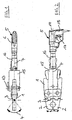
- Fig. 1 and 2 show schematically and in two views a pressing tool 5, which can be used for connecting pipes.
- Fig. 1 top view
- the tilting joint 3 is part of the pressing tongs head 1, which has a Connecting mechanism 13 with an adapter 15 and further via a pickup 16 connected to the piston 14 designed as a drive unit.
- the adapter 15 allows the inclusion of different embodiments of Pressing tongs head 1, for example, depending on the used Drive unit 6 or the resulting power transmission to the Press pliers head 1. From Fig. 1 is very easy to see that the pressing tool 5 extends substantially along an axis 7.
- FIGS. 3 and 4 likewise show a variant embodiment in two different views of the pressing tongs head 1.
- the pressing tongs head 1 extends again substantially in a plane characterized by the axis 7 can be. While in Figs. 1 and 2, a neutral position of the tilting joint is shown in Fig. 3 is an angled 90 ° position of the pressing jaws 2 shown. With the help of the tilting joint 3 is thus the tilt angle 4 of 90 ° (Degree) realized. Consequently, the pressing tongs head 1 is now substantially parallel to align the pipe section (not shown) to be connected.
- the Side view (Fig. 4) illustrates the embodiment of the tilting joint 3.
- each pressing jaw 2 has a kind of hinge joint, wherein the two Kippgelenke 3 despite each separate shafts 20 only synchronously operated with each other are, since the outside driver 21 are provided, which is a smooth, uniform and ensure synchronous tilting of the pressing jaws 2.
- This synchronization mechanism 12 is thus formed with drivers 21, on both Sides of a press pack 2 are provided. It is also possible that the tilt angle is preset via a respective adjusting wheel 19, so that the Shafts 20 of the tilting joints 3 a matching orientation or orientation exhibit.
- a locking element 8 is illustrated as a detail.
- the shaft 20 which is not only movable along its extension axis is stored, but also also can rotate, running with a bolt 10, the at certain angular positions by means of a spring element 9 in the Sink 11 of the tilting joint 3 is locked.
- the Shaft 20 against the force of the spring element 9 by means of the adjusting wheel 19 upwards to move and twist.
- Such depressions 11 and spring elements 9 can be provided in different angular positions.
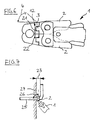
- Fig. 6 is a schematic representation of another embodiment of the pressing tongs head 1 is shown with a synchronization mechanism 12, with on both sides a pressing jaw 2 drivers 21 is realized.
- the drivers 21 (here only one is shown in the foreground) are each about a (one-sided) attachment 22 attached to a pressing jaw 2. Since the drivers 21 to in the Range of the other cheek plate 2 extend, they serve as a kind of leadership. Tilts the press jaw 21 shown below in its separate pivot joint 3, so At least one driver 21 comes into contact with the other pressing jaw 21 and so make sure that this is also tilted in the same way. So that can a substantially aligned alignment of the two pressing jaws 2 ensured become.
- FIG. 7 shows schematically an application example for a pressing tongs with a Tilting joint 3 in the pressing jaws 2. Shown is a wall 24, from which a tube 25 exits, wherein the tube 25 executed bent near the wall and then substantially is arranged parallel to a small distance 23.
- the well-known Crimping pliers are often designed to be relatively bulky, so that a vertical attachment of the pressing tool parallel to the wall 24 may be problematic.
- the pressing pliers head 1 according to the invention a preferred application, because of the tilting joints 3 allows an oblique attachment of the pressing tool is, while ensuring that the pressing jaws 21 in one Angle 26 are aligned by 90 ° during the pressing process.
- the pressing tool or the pressing tongs head described here allows a Connecting pipes, the tool being very flexible and even in confined spaces Space is easy to use.
Abstract
Description
Die Erfindung betrifft einen Presszangenkopf bzw. ein Presswerkzeug mit zwei gegenüberliegenden, schwenkbar zueinander angeordneten Pressbacken, die beispielsweise mittels einer Antriebseinheit eine Schwenkbewegung quer zu einer Achse des Presszangenkopfes ausführen. Derartige Presszangenköpfe bzw. Presswerkzeuge werden insbesondere zur Herstellung einer Rohrpressverbindung mit einem Pressfittingelement und einem darin einschiebbaren bzw. darauf aufschiebbaren Leitungsrohr eingesetzt.The invention relates to a pressing tongs head or a pressing tool with two opposite, pivotally arranged pressing jaws, for example by means of a drive unit a pivoting movement transverse to a Execute the axis of the pressing pliers head. Such pressing tongs heads or Press tools are used in particular for producing a pipe press connection with a press fitting element and a retractable or slidable therein Used pipe.
Die früher im Sanitär- und Heizungsbereich übliche Technik einer Rohrverbindung mittels Gewinderohre und/oder durch Schweißen bzw. Löten herzustellen, wurde in den letzten Jahren durch eine Verbindungsmethodik mit dem Namen "Verpresstechnik" abgelöst. Bei dieser Verpresstechnik wird ein Pressfittingelement mit einem darin einschiebbaren Leitungsrohr durch Verpressen unlösbare miteinander verbunden. Dazu wird ein Presswerkzeug, im Regelfall aus zwei Pressbacken bestehend, in geöffneter Stellung im Verbindungsbereich angesetzt und durch Aktivierung eines mit dem Presswerkzeug verbindbaren Antriebs (beispielsweise elektrisch oder hydraulisch) die Rohrpressverbindung durch Schließen des Presswerkzeugs hergestellt. Die Verpresstechnik eignet sich insbesondere für Leitungsrohre mit einem Durchmesser von 10 mm bis 100 mm.The earlier in the sanitary and heating field usual technique of a pipe connection by means of threaded pipes and / or by welding or soldering, has been named in recent years by a connection methodology "Compression technology" replaced. This compression technique becomes a pressfitting element with an insertable pipe in it by pressing insoluble connected with each other. This is a pressing tool, usually from two Pressing jaws consisting, set in the open position in the connection area and by activating a connectable with the pressing tool drive (for example electrically or hydraulically) the pipe press connection by closing made of the pressing tool. The compression technology is particularly suitable for Conduits with a diameter of 10 mm to 100 mm.
Aufgrund dieser breiten Anwendung sind gegebenenfalls unterschiedliche Presswerkzeuge bzw. verschiedene Antriebe erforderlich. Dies ist unter anderem darin begründet, dass unterschiedliche Verschwenkbereiche der Pressbacken realisiert werden müssen. Außerdem ist zu berücksichtigen, dass die zum Schließen des Presswerkzeuges erforderliche Kraft mit der Abmessung des zu verbindenden Leitungsrohres proportional ansteigt. Deshalb mussten neuere Antriebe entwickelt werden, bei denen gegebenenfalls mehrere Hübe zum Öffnen und Schließen der Pressbacken erforderlich sind. Dabei werden zum Teil Presskräfte bis 13 Tonnen realisiert. Außerdem muss für eine fluid-dichte Verbindung eine möglichst gleichmäßige Krafteinleitung über den Umfang des Leitungsrohres erfolgen, so dass in Abhängigkeit der zu verbindenden Rohre verschiedene Ausgestaltungen von Pressbacken verwendet werden.Due to this wide application, different pressing tools may be necessary or different drives required. This is among other things justified that realized different pivoting ranges of the pressing jaws Need to become. It should also be noted that the closing of the Pressing force required with the dimension of the connected Conduit rises proportionally. Therefore, newer drives had to be developed be in which, if necessary, several strokes to open and close the Pressing jaws are required. In some cases, press forces of up to 13 tons are used realized. In addition, for a fluid-tight connection a possible uniform application of force over the circumference of the conduit, so that depending on the pipes to be connected different configurations be used by pressing jaws.
Gerade im häuslichen Sanitär- und Heizungssektor werden die Rohrsysteme unter sehr beengten Platzverhältnissen verlegt. Ist nun eine Reparatur erforderlich, so sind die Rohrleitungen nur schwer erreichbar. Bei den bekannten Presswerkzeugen und den erforderlichen Antrieben besteht jedoch erheblicher Platzbedarf, der eine direkte Zugänglichkeit hin zum Verbindungsabschnitt des Rohrleitungssystems erfordert. Dies stellt viele Handwerker vor das Problem, dass größere Leitungsabschnitte ausgetauscht werden müssen, oder sogar die herkömmlichen Verbindungstechniken wieder eingesetzt werden müssen.Especially in the domestic sanitary and heating sector, the pipe systems are under Relocated very cramped space. Now is a repair required, so the pipelines are difficult to reach. In the known pressing tools and the required drives, however, there is considerable space requirement, the a direct accessibility to the connecting portion of the piping system requires. This puts many craftsmen facing the problem of having larger line sections need to be replaced, or even the conventional connection techniques must be used again.
Hiervon ausgehend ist es Aufgabe der vorliegenden Erfindung, die bekannten Probleme im Zusammenhang mit herkömmlichen Presswerkzeugen zu lösen und insbesondere einen Presszangenkopf bzw. ein Presswerkzeug anzugeben, der bzw. das auch unter beengten Platzverhältnissen einsetzbar ist. Dabei soll gleichzeitig ein sicherer Betrieb des Presswerkzeugs gewährleistet sein. Das Presswerkzeug bzw. der Presszangenkopf soll einfach aufgebaut und mechanisch stabil sein.On this basis, it is an object of the present invention, the known To solve problems related to conventional pressing tools and Specifically, specify a pressing tongs head or a pressing tool, the or which can also be used in confined spaces. It should simultaneously ensure safe operation of the pressing tool. The pressing tool or the pressing tongs head should be simple and mechanically stable.
Diese Aufgaben werden gelöst mit einer Vorrichtung gemäß den Merkmalen des
Patentanspruchs 1 bzw. einer Vorrichtung mit den Merkmalen des Patentanspruchs
2. Weitere vorteilhafte Ausgestaltungen sind in den jeweils abhängigen
Patentansprüchen formuliert. Dabei ist darauf hinzuweisen, dass die in den Patentansprüchen
aufgeführten Merkmale in beliebiger, technisch sinnvoller Weise
miteinander kombiniert werden können und weitere vorteilhafte Ausgestaltungen
der Erfindung aufzeigen. Zur detaillierteren Charakterisierung der Erfindung können
auch Inhalte der Beschreibung herangezogen werden.These objects are achieved with a device according to the features of
Die erfindungsgemäße Vorrichtung weist einen Presszanenkopf auf, der zwei gegenüberliegende, schwenkbar zueinander angeordnete Pressbacken umfasst, wobei mit den Pressbacken wenigstens ein Kippgelenk zur Erzeugung eines Kippwinkels vorgesehen ist.The device according to the invention has a press pliers head which has two opposite, includes pivotally arranged pressing jaws, wherein with the pressing jaws at least one tilting joint for generating a tilt angle is provided.
Der Presszangenkopf ist üblicherweise ein separat erhältliches Bauteil eines Presswerkzeuges, der gegebenenfalls unterschiedliche Nennweiten aufweist. Mit Nennweite ist ein Maß für die von den Pressbacken gebildete Öffnung zur Aufnahme des Leitungsrohres gemeint, also dient dieses Maß auch als Indiz dafür, welche Leitungsdurchmesser mit einem solchen Presszangenkopf bearbeitbar sind. Ein Presszangenkopf hat üblicherweise Nennweiten-Bereiche von 10 mm bis 20 mm (ist also z.B. einsetzbar für Rohre von 50-75 mm Durchmesser), um eine gleichmäßige, radial einwärtsgerichtete Kraftwirkung zu generieren. Außerdem wird gleichzeitig der Verschwenkweg der Pressbacken klein gehalten, so dass einfachere Antriebseinheiten eingesetzt werden können. So eine Begrenzung der Schwenkbewegung der Pressbacken zu ermöglichenThe pressing tongs head is usually a separately available component of a Pressing tool, which optionally has different diameters. With Nominal diameter is a measure of the opening formed by the press jaws for receiving meant by the conduit, so this measure also serves as an indication which line diameter can be machined with such a pressing tongs head are. A pressing tongs head usually has nominal width ranges of 10 mm up to 20 mm (ie it can be used, for example, for pipes of 50-75 mm diameter) to generate a uniform, radially inward force. Furthermore At the same time the Verschwenkweg the pressing jaws is kept small, so that simpler drive units can be used. Such a limitation allow the pivoting movement of the pressing jaws
Üblicherweise liegen die Pressbacken im geschlossenen Zustand im wesentlichen parallel zueinander und aneinander an. Sie weisen jeweils einen Drehpunkt auf, um den sie schwenkbar sind. Die Pressbacken selbst werden einerseits mit dem zu bearbeitenden Rohr und andererseits mit Krafteinleitungsmittel kontaktiert. Damit ist insbesondere gemeint, dass dieses Werkzeug ohne eine Pressschlinge oder ähnliche zusätzliche Bauteile auskommt, die die von den Pressbacken erzeugte Schwenkbewegung aufnehmen und selbst auf den zu bearbeitenden Rohrabschnitt einwirken. Zur Aufnahme des Rohrleitungsabschnittes sind die Pressbacken deshalb mit einer entsprechenden Aussparung versehen, wobei beide Aussparungen zusammen die Öffnung bzw. Aufnahme für ein Rohr bilden. Der Durchmesser der Öffnung entspricht wiederum in etwa den zu bearbeitenden Durchmessern der Leitungsrohre, so dass eine möglichst symmetrische, radial einwärts wirkende Kraft auf den Rohrabschnitt einwirkt.Usually, the pressing jaws are in the closed state substantially parallel to each other and to each other. They each have a pivot, around which they are pivotable. The pressing jaws themselves are on the one hand with the processing pipe and on the other hand contacted with force introduction means. In order to In particular, it is meant that this tool without a press sling or the like additional components, which produced by the pressing jaws Take up pivoting movement and even on the pipe section to be machined act. To accommodate the pipe section the pressing jaws are therefore provided with a corresponding recess, both recesses together form the opening or receptacle for a pipe. The diameter of the In turn, opening corresponds approximately to the diameters to be machined Conduits, so that as symmetrical, radially inwardly acting Force acts on the pipe section.
Während bekannte Presszangenköpfe im wesentlichen radial bzw. senkrecht zur Rohrleitung ausgerichtet werden mussten, besteht nun durch die Vorsehung des mindestens einen Kippgelenks die Möglichkeit, den Presszangenkopf in einem davon abweichenden Winkel anzusetzen. Das Kippgelenk ist so ausgestaltet, dass es die auftretenden Kräfte übertragen kann. Das Kippgelenk hat üblicherweise eine neutrale Stellung, bei der der Presszangenkopf im wesentlichen der Form herkömmlicher Presszangenköpfe entspricht. Ausgehend von dieser Neutralstellung ist es möglich, Teilbereiche des Presszangenkopfs bzw. der Pressbacken von' dieser Neutralstellung in eine und/oder andere Richtung auszulenken. Dabei wird ein Kippbereich realisiert, der sich mit dem Kippwinkel einfach beschreiben lässt. In diesem Zusammenhang sei angemerkt, dass bevorzugt jede Pressbacke ein separates Kippgelenk aufweist, wobei die Kippbewegung der Pressbacken dann auch gekoppelt ausgeführt sein kann. Außerdem ist es möglich, dass die Pressbacken und/oder der Presszangenkopf noch mindestens ein weiteres Kippgelenk und/oder eine (unveränderliche) Abwinklung aufweist, um einen größeren Kippwinkel zu erzielen.While known pressing tongs heads substantially radially or perpendicular to Pipeline had to be aligned now exists through the providence of the at least one tilting joint the possibility of the pressing tongs head in one deviate from this angle. The tilting joint is designed so that it can transmit the occurring forces. The tilt joint usually has a neutral position, wherein the pressing tongs head substantially the shape corresponds to conventional pressing tongs heads. Starting from this neutral position is it possible to use sections of the pressing tongs head or pressing jaws of ' deflect this neutral position in one and / or other direction. It will implemented a tilting range, which can be easily described with the tilt angle. In this connection it should be noted that preferably each pressing jaw is a separate one Tilting joint, wherein the tilting movement of the pressing jaws then can also be executed coupled. It is also possible that the pressing jaws and / or the pressing tongs head still at least one other tilting joint and / or having an (unchangeable) bend to a larger tilt angle to achieve.
Für eine Vielzahl von Anwendungen wird es ausreichend sein, wenn das Kippgelenk ausgehend von der Neutralstellung einen Kippwinkel hin in eine Richtung, bis beispielsweise 90°, bereitstellt. In Spezialanwendungen kann es jedoch auch erforderlich sein, dass das Kippgelenk ausgehend von der Neutralstellung in beide Richtungen mit einem Kippwinkel kippbar ist, so dass sich beispielsweise ein gesamter Kippwinkel von ca. 180° verwirklichen lässt. Ist das Kippgelenk in einer ausgelenkten Position, befinden sich Teilbereiche des Presszangenkopfes in einer nicht-senkrechten Lage zum Leitungsrohrabschnitt bzw. nicht-fluchtend zur Öffnung der Pressbacken zur Aufnahme des Rohrleitungsabschnittes. Vielmehr liegen diese beispielsweise bei einer 90°-Kippung parallel zum Rohrleitungsabschnitt. Somit ist gewährleistet, dass der Presszangenkopf bzw. das Presswerkzeug sehr dicht an dem zu verbindenden Rohrleitungsabschnitt entlang geführt wird und auch unter beengten Platzverhältnissen eine Pressverbindung realisiert werden kann.For a variety of applications, it will be sufficient if the tilting joint starting from the neutral position, a tilt angle in one direction, up to 90 °, for example. However, it can work in special applications as well It may be necessary for the toggle joint to move from neutral to both Directions is tiltable with a tilt angle, so that, for example, a Total tilt angle of about 180 ° can be realized. Is the tilting joint in one deflected position, are parts of the pressing tongs head in one non-vertical position to the pipe section or not in alignment with the opening the pressing jaws for receiving the pipe section. Rather, lie this, for example, at a 90 ° tilt parallel to the pipe section. This ensures that the pressing tongs head or the pressing tool very close to the pipe section to be connected along is realized and even under confined space a press connection can be.
Gemäß einem weiteren Aspekt der Erfindung wird eine Vorrichtung mit einem Presswerkzeug vorgeschlagen, welches einen Presszangenkopf mit zwei gegenüberliegenden, schwenkbar zueinander angeordneten Pressbacken umfasst, sowie eine Antriebseinheit zur Bewirkung der Schwenkbewegung quer zu einer Achse, wobei mit den Pressbacken wenigstens ein Kippgelenk zur Erzeugung eines Kippwinkels vorgesehen ist. Unter einer Antriebseinheit ist insbesondere eine solche zu verstehen, welche mittels einem elektrischen bzw. hydraulischen Antriebsaggregat die zur Verschwenkung der Pressbacken erforderliche Kraft aufbringt. Dabei wird üblicherweise eine Kraft entlang der Achse erzeugt, die anschließend zur Schwenkbewegung umgewandelt wird. Mindestens ein Kippgelenk ist nun mit den Pressbacken gebildet, wobei bevorzugt jede Pressbacke mit mindestens einem separaten Kippgelenk ausgeführt ist. Weitere Kippgelenke können z.B. am Presszangenkopf vorgesehen sein. Bezüglich weiterer Fähigkeiten bzw. Ausführungsvarianten des Kippgelenkes wird auf die entsprechenden Sachverhalte des Kippgelenkes des Presszangenkopfes verwiesen.According to a further aspect of the invention, a device with a Pressing tool proposed which a pressing tongs head with two opposite, includes pivotally arranged pressing jaws, and a drive unit for effecting the pivoting movement transverse to an axis, wherein with the pressing jaws at least one tilting joint for generating a Tilting angle is provided. Under a drive unit is in particular a to understand those which by means of an electric or hydraulic drive unit the force required to pivot the press jaws applies. In this case, a force is usually generated along the axis, which then is converted to the pivoting movement. At least one tilting joint is now formed with the pressing jaws, preferably each pressing jaw with at least a separate tilting joint is executed. More tilting joints can e.g. be provided on the pressing tongs head. Regarding other skills or Variants of the tilting joint is on the corresponding facts the tilting joint of the pressing tongs head referenced.
Gemäß einer weiteren Ausgestaltung der Erfindung bildet das Kippgelenk einen Kippwinkel im Bereich von 120° bis 30°. Insbesondere für den Fall, dass ein einseitiges Abknicken von Teilbereichen des Presswerkzeuges bzw. des Presszangenkopfes nur gewünscht ist, ist ein Kippwinkel bis 90° ausreichend. Die einzelnen Kippwinkel können stufenlos eingestellt werden, es ist jedoch auch möglich, dass nur bestimmte Kippwinkel, beispielsweise in gleich großen Intervallen von 30°, einstellbar sind.According to a further embodiment of the invention, the tilting joint forms a Tilt angle in the range of 120 ° to 30 °. Especially in the case of a one-sided Kinking of parts of the pressing tool or the pressing tongs head is only desired, a tilt angle of 90 ° is sufficient. The single ones Tilt angles can be adjusted continuously, but it is also possible that only certain tilt angles, for example, at equal intervals of 30 °, are adjustable.
Gemäß einer vorteilhaften Weiterbildung umfasst das Kippgelenk mindestens ein Rastelement zur Fixierung wenigstens eines vorgegebenen Kippwinkels. Gerade für den Fall, dass keine stufenlose Einstellung des Kippwinkels vorgegeben ist, ist es sinnvoll, eine exakte Positionierung der gegeneinander gekippten Teilbereiche des Presswerkzeuges bzw. des Presszangenkopfes zu gewährleisten. Hierzu können Justier- bzw. Einstellhilfen vorgesehen sein, wie beispielsweise mittels wenigstens eines Rastelementes. Das Rastelement greift mit entsprechenden Ausnehmungen des Presswerkzeugs ein, wenn ein bestimmter Kippwinkel erreicht wurde. Allgemein kann das Rastelement ein Element des abkippbaren Teils oder des feststehenden Teils des Presswerkzeuges sein, wobei in dem jeweils anderen Teil eine entsprechende Einrastmöglichkeit vorgesehen ist. Das Rastelement stellt auch sicher, dass dieser Kippwinkel bei der Bearbeitung des Rohrleitungsabschnittes nicht verändert wird.According to an advantageous development, the tilting joint comprises at least one Locking element for fixing at least one predetermined tilt angle. Just in the event that no stepless adjustment of the tilt angle is given, is it makes sense, an exact positioning of the mutually tilted portions to ensure the pressing tool or the pressing tongs head. You can do this Adjustment or adjustment aids may be provided, such as by means of at least a locking element. The locking element engages with corresponding recesses of the pressing tool when a certain tilt angle is reached has been. In general, the locking element can be an element of the tiltable part or be the fixed part of the pressing tool, wherein in the other Part a corresponding snap-in is provided. The locking element provides Also, make sure that this tilt angle when machining the pipe section not changed.
Dabei ist es besonders vorteilhaft, dass das mindestens eine Rastelement zumindest ein Federelement und einen beweglichen Bolzen hat, so dass der Bolzen mit dem Federelement hin zu einer Senke des Kippgelenkes auslenkbar ist. Auf diese Weise wird einer Art Rast-Verschluss gebildet, der das Kippgelenk in einer bestimmten Position bzw. mit einem bestimmten Kippwinkel arretiert. Mit dem Begriff "Bolzen" sind eine Vielzahl unterschiedlicher Formelemente umfasst, die zur Durchführung einer solchen Rastfunktion geeignet sind, beispielsweise auch Kugeln, Vorsprünge, Rastnasen, etc.. Dieser Bolzen ist beweglich angeordnet, das heißt insbesondere relativ zu Teilbereichen des Kippgelenkes verschiebbar. Ist die gewünschte Position des Kippgelenks bzw. der vorgegebene Kippwinkel erreicht, wird der Bolzen mit dem Federelement in eine Senke gedrückt und bildet dort einen Formschluss bzw. Kraftschluss. Damit ist gewährleistet, dass ein weiteres Kippen ohne zusätzliche Maßnahmen verhindert ist. Die Senke hat bevorzugt im wesentlichen eine an den Bolzen angepasste Kontur.It is particularly advantageous that the at least one locking element at least a spring element and a movable bolt has, so that the bolt with the spring element is deflected towards a depression of the tilting joint. To this Way, a kind of latching closure is formed, which the tilting joint in a certain Position or locked with a certain tilt angle. With the Term "bolts" are a variety of different form elements that includes are suitable for performing such a latching function, for example Balls, projections, detents, etc .. This bolt is movably arranged, the is in particular displaceable relative to subregions of the tilting joint. Is the desired position of the tilting joint or reaches the predetermined tilt angle, The bolt is pressed with the spring element in a sink and forms there a positive connection or adhesion. This ensures that another Tilting without additional measures is prevented. The valley is preferred in the essentially a contour adapted to the bolt.
Gemäß einer weiteren Ausgestaltung der Vorrichtung hat jede Pressbacke ein Kippgelenk, wobei ein Synchronisationsmechanismus zur Gewährleistung des gleichen Kippwinkels vorgesehen ist. Die Vorsehung der Kippgelenke direkt im Presszangenkopf hat den Vorteil, dass diese Presszangenköpfe auf herkömmliche Presswerkzeuge aufgesetzt bzw. mit diesen kombiniert werden können. Damit wird in einfacher Art und Weise ein Ersatzteil vorgeschlagen, welches die herkömmlichen Presswerkzeuge ergänzt. Um sicherzustellen, dass die Kippgelenke in den Pressbacken jeweils die gleiche Kippwinkelstellung aufweisen, sind entsprechende Mittel vorzusehen. Ein Synchronisationsmechanismus kann beispielsweise dadurch realisiert werden, dass eine Verbindung beider Kippgelenke' bzw. der beiden Pressbacken vorgesehen ist, so dass ein unabhängiger Betrieb nur eines der beiden Kippgelenke in der Pressbacke nicht möglich ist. So kann beispielsweise an einer Pressbacke eine Klappe, ein Führungsstift oder ein ähnliches Bauteil vorgesehen sein, das als eine Art Mitnehmer fungiert, also den beweglichen bzw. kippbaren Teil der anderen Pressbacke zwingt, der eigenen Kippbewegung zu folgen. Dabei ist sicherzustellen, dass dieser Mitnehmer auch im geöffneten bzw. ausgeschwenkten Zustand der Pressbacken noch eine Führung darstellt. Selbstverständlich ist es auch möglich, solche Mitnehmer an anderen Stellen des Presszangenkopfes vorzusehen, wobei dieser dann bevorzugt mit beiden Pressbacken in Kontakt steht. Dadurch wird auch bei solchen Ausgestaltungen der Pressbacken sichergestellt, dass sie jeweils auf den gleichen Rohrquerschnitt einwirken und eine flüssigkeits- und ggf. gasdichte Pressverbindung generiert wird.According to a further embodiment of the device, each pressing jaw has one Tilting joint, with a synchronization mechanism to ensure the same tilt angle is provided. The providence of the tilting joints directly in the Press tongs head has the advantage that these pressing tongs heads on conventional Press tools can be placed or combined with these. In order to is proposed in a simple manner, a spare part, which is the conventional Compressed tools added. To ensure that the tilting joints in the press jaws each have the same Kippwinkelstellung are appropriate Provide funds. A synchronization mechanism may be, for example be realized by a connection of both tilting joints' or the two pressing jaws is provided, so that an independent operation only one of the two tilting joints in the pressing jaw is not possible. So, for example on a pressing jaw a flap, a guide pin or the like Be provided component that acts as a kind of driver, so the movable or tilting part of the other pressing jaw forces its own tilting movement to follow. Make sure that this driver is also in the open or swung-out state of the pressing jaws still represents a guide. Of course it is also possible to use such carriers in other places of the Provide pressing tongs head, this then preferably with two pressing jaws in contact. As a result, even in such embodiments of the pressing jaws ensure that they each act on the same pipe cross-section and a liquid and possibly gas-tight press connection is generated.
Außerdem wird auch vorgeschlagen, dass das Presswerkzeug einen wiederlösbaren Verbindungsmechanismus für den Presszangenkopf hat. Damit ist ermöglicht, dass jeweils für den Anwendungsfall geeignete Presszangenköpfe mit dem Presswerkzeug verbunden werden können, die also beispielsweise das entsprechende Nennmaß aufweisen. Als lösbare Verbindung bieten sich insbesondere Schraub- oder Schnappverbindungen an. Auch andere Riegelsysteme sind unter Umständen einsetzbar.In addition, it is also proposed that the pressing tool a wiederlösbaren Connection mechanism for the pressing tongs head has. This makes it possible that each suitable for the application pressing tongs heads with the pressing tool can be connected, so for example, the corresponding Nominal size. As a detachable connection, in particular screw or snap connections. Other locking systems are under circumstances used.
Gemäß einer Weiterbildung des Presswerkzeuges weist dieses eine Antriebseinheit mit einem Hubkolben auf, der die Schwenkbewegung der Pressbacken bewirkt. Der Hubkolben kann hydraulisch oder elektrisch betrieben werden. Die lineare Bewegung des Hubkolbens wird durch geeignete Mittel in die Schwenkbewegung der Pressbacken transferiert. Die Kraftübertragung bzw. die Übertragung der Schwenkbewegung erfolgt dabei über das Kippgelenk hinweg.According to a development of the pressing tool, this has a drive unit with a reciprocating piston, which causes the pivoting movement of the pressing jaws. The reciprocating piston can be operated hydraulically or electrically. The linear movement of the reciprocating piston is by suitable means in the pivoting movement transferred the pressing jaws. The power transmission or the transmission The pivoting movement takes place via the tilting joint.
Die Erfindung sowie das technische Umfeld wird nachfolgend mit Bezug auf die Figuren näher erläutert. In den Figuren sind besonders bevorzugte Ausführungsvarianten der Erfindung gezeigt, die Erfindung ist jedoch nicht darauf begrenzt. Es zeigen:
- Fig. 1,2
- schematisch in einer Draufsicht und in einer Seitenansicht eine Ausführungsvariante des erfindungsgemäßen Presswerkzeuges,
- Fig. 3,4,5
- schematisch und in einer Draufsicht sowie einer Seitenansicht eine Ausführungsvariante eines Presszangenkopfes,
- Fig. 6
- schematisch eine weitere Ausführungsvariante des Presszangenkopfes mit einem Synchronisationsmechanismus, und
- Fig.7
- schematisch ein Anwendungsbeispiel für eine Presszange mit einem Kippgelenk in den Pressbacken.
- Fig. 1.2
- schematically in a plan view and in a side view of an embodiment of the pressing tool according to the invention,
- Fig. 3,4,5
- schematically and in a plan view and a side view of an embodiment of a pressing tongs head,
- Fig. 6
- schematically a further embodiment of the pressing tongs head with a synchronization mechanism, and
- Figure 7
- schematically an example of application for a pressing tongs with a tilting joint in the pressing jaws.
Fig. 1 und 2 zeigen schematisch und in zwei Ansichten ein Presswerkzeug 5, welches
zur Verbindung von Rohrleitungen einsetzbar ist. In der Fig. 1 (Draufsicht)
ist das Kippgelenk 3 sowie den damit erzeugbaren Kippwinkel 4 deutlich zu erkennen.
Das Kippgelenk 3 ist dabei Teil des Presszangenkopfes 1, der über einen
Verbindungsmechanismus 13 mit einem Adapter 15 und weiter über einen Aufnehmer
16 mit der als Hubkolben 14 ausgebildeten Antriebseinheit verbunden.
Der Adapter 15 ermöglicht die Aufnahme unterschiedlicher Ausgestaltungen des
Presszangenkopfs 1, beispielsweise in Abhängigkeit von der zum Einsatz gelangenden
Antriebseinheit 6 bzw. der daraus resultierenden Kraftübertragung auf den
Presszangenkopf 1. Aus Fig. 1 ist sehr gut zu erkennen, dass sich das Presswerkzeug
5 im wesentlichen entlang einer Achse 7 erstreckt. Soll nun ein zu verbindender
Rohrabschnitt zwischen die Pressbacken 2 des Presszangenkopfes 1 angeordnet
werden, mussten bislang diese Achse 7 im wesentlichen senkrecht zur
Rohrleitungsachse ausgerichtet werden. Das Kippgelenk 3 bietet nun die Möglichkeit,
eine hiervon abweichende Ausrichtung des Presswerkzeugs 5 zum (nicht
dargestellten) Leitungsabschnitt zu ermöglichen. Aus Fig. 2 (Seitenansicht) ist zu
erkennen, dass das Presswerkzeug 5 einen Handgriff 18 mit einem Schalthebel 17
zur Aktivierung der Antriebseinheit 6 aufweist. Demnach ist das Presswerkzeug 5
mit einer Hand zu bedienen. Die Antriebseinheit 6 ist mit einem Hubkolben 14
ausgeführt, der in Richtung der Achse 7 eine Kraft generiert. Diese wird über den
Aufnehmer 16 und den Adapter 15 auf die Pressbacken 2 des Presszangenkopfes
1 übertragen, so dass dieser die mit schwarzen Pfeilen angedeutete Schwenkbewegung
zum Öffnen und Schließen der gegenüberliegend angeordneten Pressbacken
2 ermöglicht. Das so gestaltete Presswerkzeug 5 ist sehr handlich und flexibel
einsetzbar.Fig. 1 and 2 show schematically and in two views a
Die Fig. 3 und 4 zeigen ebenfalls in zwei unterschiedlichen Ansichten eine Ausführungsvariante
des Presszangenkopfes 1. Der Presszangenkopf 1 erstreckt sich
wiederum im wesentlichen in einer Ebene, die durch die Achse 7 charakterisiert
werden kann. Während in Fig. 1 und 2 eine neutrale Stellung des Kippgelenkes
dargestellt ist, ist in der Fig. 3 eine um 90° abgewinkelte Position der Pressbacken
2 dargestellt. Mit Hilfe des Kippgelenkes 3 ist somit der Kippwinkel 4 von 90°
(Grad) realisiert. Folglich ist der Presszangenkopf 1 nun im wesentlichen parallel
zum zu verbindenden Rohrleitungsabschnitt (nicht dargestellt) auszurichten. Die
Seitenansicht (Fig. 4) veranschaulicht die Ausführungsvariante des Kippgelenkes
3. Dabei weist jede Pressbacke 2 eine Art Scharniergelenk auf, wobei die beiden
Kippgelenke 3 trotz jeweils separater Wellen 20 nur synchron zu einander betreibbar
sind, da außen Mitnehmer 21 vorgesehen sind, die ein leichtgängiges, gleichmäßiges
und synchrones Kippen der Pressbacken 2 gewährleisten. Dieser Synchronisationsmechanismus
12 wird also mit Mitnehmern 21 gebildet, die auf beiden
Seiten einer Presspacke 2 vorgesehen sind. Außerdem ist auch möglich, dass
der Kippwinkel über jeweils ein Stellrad 19 voreingestellt wird, so dass die
Wellen 20 der Kippgelenke 3 eine übereinstimmende Ausrichtung bzw. Orientierung
aufweisen.FIGS. 3 and 4 likewise show a variant embodiment in two different views
of the
In Fig. 5 ist als Detail die Ausgestaltung eines Rastelementes 8 veranschaulicht.
Dazu ist die Welle 20, die nicht nur entlang ihrer Erstreckungsachse beweglich
gelagert ist, sondern zudem auch noch rotieren kann, mit einem Bolzen 10 ausgeführt,
der bei bestimmten Winkelstellungen mittels einem Federelement 9 in die
Senke 11 des Kippgelenkes 3 arretiert wird. Zum Lösen dieser Arretierung ist die
Welle 20 gegen die Kraft des Federelementes 9 mittels dem Stellrad 19 nach oben
zu bewegen und zu verdrehen. Derartige Senken 11 bzw. Federelemente 9 können
in verschiedenen Winkelpositionen vorgesehen sein.In Fig. 5, the embodiment of a
In Fig. 6 ist schematisch eine weitere Ausführungsvariante des Presszangenkopfes
1 mit einem Synchronisationsmechanismus 12 dargestellt, der mit beidseitig an
einer Pressbacke 2 Mitnehmern 21 realisiert ist. Die Mitnehmer 21 (wobei hier
nur der eine im Vordergrund gezeigt ist) sind jeweils über eine (einseitige) Befestigung
22 an einer Pressbacke 2 befestigt. Da sich die Mitnehmer 21 bis in den
Bereich der anderen Pressbacke 2 erstrecken, dienen sie als eine Art Führung.
Kippt die unten dargestellte Pressbacke 21 in ihrem separaten Kippgelenk 3, so
kommt mindestens ein Mitnehmer 21 mit der anderen Pressbacke 21 in Kontakt
und sogt so dafür, dass diese ebenfalls in gleicher Weise gekippt wird. Damit kann
eine im wesentlichen fluchtende Ausrichtung der beiden Pressbacken 2 sichergestellt
werden.In Fig. 6 is a schematic representation of another embodiment of the
Fig.7 zeigt schematisch ein Anwendungsbeispiel für eine Presszange mit einem
Kippgelenk 3 in den Pressbacken 2. Dargestellt ist eine Wand 24, aus der ein Rohr
25 austritt, wobei das Rohr 25 in Wandnähe gebogen ausgeführt und dann im wesentlichen
parallel mit einem kleinen Abstand 23 angeordnet ist. Die bekannten
Presszangen sind oft relativ großvolumig ausgeführt, so dass ein senkrechtes Ansetzen
des Presswerkzeuges parallel zur Wand 24 problematisch sein kann. Hier
bietet nun der erfindungsgemäße Presszangenkopf 1 eine bevorzugte Anwendung,
da mittels der Kippgelenke 3 ein schräges Ansetzen des Presswerkzeugs ermöglicht
ist, wobei gleichzeitig sichergestellt ist, dass die Pressbacken 21 in einem
Winkel 26 von 90° während des Pressvorgangs ausgerichtet sind.7 shows schematically an application example for a pressing tongs with a
Tilting joint 3 in the
Das hier beschriebene Presswerkzeug bzw. der Presszangenkopf ermöglicht ein Verbinden von Rohren, wobei das Werkzeug sehr flexibel und auch unter beengten Platzverhältnissen einfach einsetzbar ist. The pressing tool or the pressing tongs head described here allows a Connecting pipes, the tool being very flexible and even in confined spaces Space is easy to use.
- 11
- PresszangenkopfPress pliers head
- 22
- Pressbackepressing jaw
- 33
- Kippgelenktilting joint
- 44
- Kippwinkeltilt angle
- 55
- Presswerkzeugpress tool
- 66
- Antriebseinheitdrive unit
- 77
- Achseaxis
- 88th
- Rastelementlocking element
- 99
- Federelementspring element
- 1010
- Bolzenbolt
- 1111
- Senkedepression
- 1212
- Synchronisationsmechanismussynchronization mechanism
- 1313
- Verbindungsmechanismusjoint mechanism
- 1414
- Hubkolbenreciprocating
- 1515
- Adapteradapter
- 1616
- Aufnehmerpickup
- 1717
- Schalthebelgear lever
- 1818
- Handgriffhandle
- 1919
- Stellradthumbwheel
- 2020
- Wellewave
- 2121
- Mitnehmertakeaway
- 2222
- Befestigungattachment
- 2323
- Abstanddistance
- 2424
- Wandwall
- 2525
- Rohrpipe
- 2626
- Winkelangle
Claims (8)
Priority Applications (2)
| Application Number | Priority Date | Filing Date | Title |
|---|---|---|---|
| PL05001177T PL1559513T3 (en) | 2004-01-31 | 2005-01-21 | Pressing tool with pivotable jaws |
| SI200531341T SI1559513T1 (en) | 2004-01-31 | 2005-01-21 | Pressing tool with pivotable jaws |
Applications Claiming Priority (2)
| Application Number | Priority Date | Filing Date | Title |
|---|---|---|---|
| DE102004005558A DE102004005558B4 (en) | 2004-01-31 | 2004-01-31 | Pressing tongs head and pressing tool |
| DE102004005558 | 2004-01-31 |
Publications (3)
| Publication Number | Publication Date |
|---|---|
| EP1559513A2 true EP1559513A2 (en) | 2005-08-03 |
| EP1559513A3 EP1559513A3 (en) | 2009-12-30 |
| EP1559513B1 EP1559513B1 (en) | 2011-05-25 |
Family
ID=34638842
Family Applications (1)
| Application Number | Title | Priority Date | Filing Date |
|---|---|---|---|
| EP05001177A Not-in-force EP1559513B1 (en) | 2004-01-31 | 2005-01-21 | Pressing tool with pivotable jaws |
Country Status (7)
| Country | Link |
|---|---|
| EP (1) | EP1559513B1 (en) |
| AT (1) | ATE510660T1 (en) |
| DE (1) | DE102004005558B4 (en) |
| DK (1) | DK1559513T3 (en) |
| ES (1) | ES2366475T3 (en) |
| PL (1) | PL1559513T3 (en) |
| SI (1) | SI1559513T1 (en) |
Cited By (5)
| Publication number | Priority date | Publication date | Assignee | Title |
|---|---|---|---|---|
| EP1972394A1 (en) | 2007-03-22 | 2008-09-24 | Rothenberger AG | Pressing device for tubular workpieces |
| DE102007047339A1 (en) | 2007-10-04 | 2009-04-09 | Novartec Ag | Pressing tool for pressing casing part and work piece i.e. fitting with pipe-ends, has pressing surfaces lying partially between die stocks, and die stocks connected with pressing units in detachable manner in middle area of surfaces |
| US20090293577A1 (en) * | 2008-05-28 | 2009-12-03 | Emerson Electric Co. | Jaw set and jaw set system with hinged jaw arms for use in a pressing tool |
| DE102008057424A1 (en) | 2008-11-12 | 2010-05-27 | Interprecise Donath Gmbh | Attachment device for a pipe pressing machine |
| CN109822506A (en) * | 2017-11-23 | 2019-05-31 | 维家技术有限及两合公司 | Adjustable clamp for compression tool |
Families Citing this family (1)
| Publication number | Priority date | Publication date | Assignee | Title |
|---|---|---|---|---|
| DE102016100823A1 (en) * | 2016-01-19 | 2017-07-20 | Propress Gmbh | pressing device |
Citations (6)
| Publication number | Priority date | Publication date | Assignee | Title |
|---|---|---|---|---|
| US5255579A (en) | 1991-01-15 | 1993-10-26 | Pierre Fortin | Pivoting jaw locking tool |
| DE19826110A1 (en) | 1998-06-12 | 1999-12-23 | Siegfried Leverberg | Electro-hydraulic device for pressing pipe connections |
| DE20016060U1 (en) | 2000-09-16 | 2000-12-28 | Volp Rainer | Crimping pliers |
| DE20018312U1 (en) | 2000-10-26 | 2001-05-10 | Franz Viegener Ii Gmbh & Co Kg | Press tool |
| DE10029761C1 (en) | 2000-06-16 | 2001-10-31 | Mapress Gmbh & Co Kg | Tube press joint making process involves applying pressing work of drive by more than one stroke |
| US20030230130A1 (en) | 2002-06-17 | 2003-12-18 | Emerson Electric Co. | Assembly for articulating crimp ring and actuator |
Family Cites Families (2)
| Publication number | Priority date | Publication date | Assignee | Title |
|---|---|---|---|---|
| DE20303228U1 (en) * | 2003-02-27 | 2003-04-30 | Hsien Chih Ching | Angle adjustment mechanism for spanner end has a hand grip and head and axial bolt also an outer nose (12,13) |
| US7516990B2 (en) * | 2003-05-15 | 2009-04-14 | Mueller Industries, Inc. | Fluid conduit system and fittings therefor |
-
2004
- 2004-01-31 DE DE102004005558A patent/DE102004005558B4/en not_active Expired - Fee Related
-
2005
- 2005-01-21 SI SI200531341T patent/SI1559513T1/en unknown
- 2005-01-21 ES ES05001177T patent/ES2366475T3/en active Active
- 2005-01-21 AT AT05001177T patent/ATE510660T1/en active
- 2005-01-21 PL PL05001177T patent/PL1559513T3/en unknown
- 2005-01-21 DK DK05001177.4T patent/DK1559513T3/en active
- 2005-01-21 EP EP05001177A patent/EP1559513B1/en not_active Not-in-force
Patent Citations (6)
| Publication number | Priority date | Publication date | Assignee | Title |
|---|---|---|---|---|
| US5255579A (en) | 1991-01-15 | 1993-10-26 | Pierre Fortin | Pivoting jaw locking tool |
| DE19826110A1 (en) | 1998-06-12 | 1999-12-23 | Siegfried Leverberg | Electro-hydraulic device for pressing pipe connections |
| DE10029761C1 (en) | 2000-06-16 | 2001-10-31 | Mapress Gmbh & Co Kg | Tube press joint making process involves applying pressing work of drive by more than one stroke |
| DE20016060U1 (en) | 2000-09-16 | 2000-12-28 | Volp Rainer | Crimping pliers |
| DE20018312U1 (en) | 2000-10-26 | 2001-05-10 | Franz Viegener Ii Gmbh & Co Kg | Press tool |
| US20030230130A1 (en) | 2002-06-17 | 2003-12-18 | Emerson Electric Co. | Assembly for articulating crimp ring and actuator |
Cited By (7)
| Publication number | Priority date | Publication date | Assignee | Title |
|---|---|---|---|---|
| EP1972394A1 (en) | 2007-03-22 | 2008-09-24 | Rothenberger AG | Pressing device for tubular workpieces |
| DE102007047339A1 (en) | 2007-10-04 | 2009-04-09 | Novartec Ag | Pressing tool for pressing casing part and work piece i.e. fitting with pipe-ends, has pressing surfaces lying partially between die stocks, and die stocks connected with pressing units in detachable manner in middle area of surfaces |
| US20090293577A1 (en) * | 2008-05-28 | 2009-12-03 | Emerson Electric Co. | Jaw set and jaw set system with hinged jaw arms for use in a pressing tool |
| DE102008057424A1 (en) | 2008-11-12 | 2010-05-27 | Interprecise Donath Gmbh | Attachment device for a pipe pressing machine |
| DE102008057424B4 (en) * | 2008-11-12 | 2010-09-02 | Interprecise Donath Gmbh | Attachment device for a pipe pressing machine |
| CN109822506A (en) * | 2017-11-23 | 2019-05-31 | 维家技术有限及两合公司 | Adjustable clamp for compression tool |
| CN109822506B (en) * | 2017-11-23 | 2021-12-14 | 维家技术有限及两合公司 | Movable pliers for extrusion tool |
Also Published As
| Publication number | Publication date |
|---|---|
| EP1559513A3 (en) | 2009-12-30 |
| DE102004005558B4 (en) | 2006-04-20 |
| PL1559513T3 (en) | 2011-10-31 |
| DK1559513T3 (en) | 2011-08-22 |
| SI1559513T1 (en) | 2011-10-28 |
| EP1559513B1 (en) | 2011-05-25 |
| ATE510660T1 (en) | 2011-06-15 |
| DE102004005558A1 (en) | 2005-08-18 |
| ES2366475T3 (en) | 2011-10-20 |
Similar Documents
| Publication | Publication Date | Title |
|---|---|---|
| EP1941975B1 (en) | Hydraulic pliers for grouting of workpieces | |
| DE102007031412B4 (en) | clamping device | |
| EP3030209B1 (en) | Clamping claw for attaching to a slide rail of an operating table | |
| DE19924087C2 (en) | Pliers for crimping sockets, pipes, cable lugs and the like | |
| DE10346241B3 (en) | Workpiece compression pliers e.g. for compression of pipe or compression fitting, has one hand lever divided into 2 partial levers for 2-stage compression of workpiece | |
| EP0958108B1 (en) | Clamp clip | |
| EP1559513B1 (en) | Pressing tool with pivotable jaws | |
| DE112014001451T5 (en) | Multiple tool gears and attachments for a rotary tool | |
| EP1726406A2 (en) | Pressing tool, press ring and crimping pliers | |
| EP2080592B1 (en) | Crimping ring | |
| EP3180555B1 (en) | Tapping fitting | |
| DE102008007303B4 (en) | expanding pliers | |
| EP2732778B1 (en) | Medical instrument | |
| EP1839814A2 (en) | Pressing tool, press ring and crimping pliers | |
| DE102009023020A1 (en) | Jaw set and jaw set system with hinged jaw arms for use in a press tool | |
| EP3366399A1 (en) | Handheld electrical appliance | |
| DE202010006494U1 (en) | Hand-operated clamping tools | |
| DE3110348C2 (en) | Chuck for a turning tool | |
| DE10231724B4 (en) | Supporting collar | |
| DE20318618U1 (en) | Pair of jaws for press tool has connecting straps with pivot pins and presses pair of crimping tools together when tail ends are forced apart by rollers on longitudinally-moving shaft | |
| DE3206907C2 (en) | Pliers-like tool, especially universal pliers | |
| DE102004015892A1 (en) | Closing machine drive with adjustable articulation point | |
| DE10104650C1 (en) | Device to perforate, stamp, emboss, flange or join sheet metal parts, especially to construct chassis, has jaw part with pivoting push arm and counter bearing with pivot drive for push arm | |
| WO2010079211A2 (en) | Pliers for establishing a sliding-sleeve connection | |
| CH682992A5 (en) | Clamping claw for separating and attaching lockable or engageable elements - has fork elements on one end of each of straight and angled legs, forks having curved segment with stepped radii on inside surface |
Legal Events
| Date | Code | Title | Description |
|---|---|---|---|
| PUAI | Public reference made under article 153(3) epc to a published international application that has entered the european phase |
Free format text: ORIGINAL CODE: 0009012 |
|
| 17P | Request for examination filed |
Effective date: 20050121 |
|
| AK | Designated contracting states |
Kind code of ref document: A2 Designated state(s): AT BE BG CH CY CZ DE DK EE ES FI FR GB GR HU IE IS IT LI LT LU MC NL PL PT RO SE SI SK TR |
|
| AX | Request for extension of the european patent |
Extension state: AL BA HR LV MK YU |
|
| PUAL | Search report despatched |
Free format text: ORIGINAL CODE: 0009013 |
|
| AK | Designated contracting states |
Kind code of ref document: A3 Designated state(s): AT BE BG CH CY CZ DE DK EE ES FI FR GB GR HU IE IS IT LI LT LU MC NL PL PT RO SE SI SK TR |
|
| AX | Request for extension of the european patent |
Extension state: AL BA HR LV MK YU |
|
| 17Q | First examination report despatched |
Effective date: 20100129 |
|
| AKX | Designation fees paid |
Designated state(s): AT BE BG CH CY CZ DE DK EE ES FI FR GB GR HU IE IS IT LI LT LU MC NL PL PT RO SE SI SK TR |
|
| GRAP | Despatch of communication of intention to grant a patent |
Free format text: ORIGINAL CODE: EPIDOSNIGR1 |
|
| RIC1 | Information provided on ipc code assigned before grant |
Ipc: B25B 27/10 20060101AFI20110119BHEP |
|
| RTI1 | Title (correction) |
Free format text: PRESSING TOOL WITH PIVOTABLE JAWS |
|
| GRAS | Grant fee paid |
Free format text: ORIGINAL CODE: EPIDOSNIGR3 |
|
| GRAA | (expected) grant |
Free format text: ORIGINAL CODE: 0009210 |
|
| AK | Designated contracting states |
Kind code of ref document: B1 Designated state(s): AT BE BG CH CY CZ DE DK EE ES FI FR GB GR HU IE IS IT LI LT LU MC NL PL PT RO SE SI SK TR |
|
| REG | Reference to a national code |
Ref country code: GB Ref legal event code: FG4D Free format text: NOT ENGLISH |
|
| REG | Reference to a national code |
Ref country code: CH Ref legal event code: EP |
|
| REG | Reference to a national code |
Ref country code: IE Ref legal event code: FG4D Free format text: LANGUAGE OF EP DOCUMENT: GERMAN |
|
| REG | Reference to a national code |
Ref country code: DE Ref legal event code: R096 Ref document number: 502005011414 Country of ref document: DE Effective date: 20110707 |
|
| REG | Reference to a national code |
Ref country code: CH Ref legal event code: PCOW Free format text: BIRK, MICHAEL;DREIKOENIGENSTRASSE 13;53343 WACHTBERG (DE) Ref country code: CH Ref legal event code: NV Representative=s name: ISLER & PEDRAZZINI AG |
|
| REG | Reference to a national code |
Ref country code: DK Ref legal event code: T3 |
|
| REG | Reference to a national code |
Ref country code: SE Ref legal event code: TRGR |
|
| REG | Reference to a national code |
Ref country code: NL Ref legal event code: T3 |
|
| REG | Reference to a national code |
Ref country code: ES Ref legal event code: FG2A Ref document number: 2366475 Country of ref document: ES Kind code of ref document: T3 Effective date: 20111020 |
|
| PG25 | Lapsed in a contracting state [announced via postgrant information from national office to epo] |
Ref country code: PT Free format text: LAPSE BECAUSE OF FAILURE TO SUBMIT A TRANSLATION OF THE DESCRIPTION OR TO PAY THE FEE WITHIN THE PRESCRIBED TIME-LIMIT Effective date: 20110926 Ref country code: LT Free format text: LAPSE BECAUSE OF FAILURE TO SUBMIT A TRANSLATION OF THE DESCRIPTION OR TO PAY THE FEE WITHIN THE PRESCRIBED TIME-LIMIT Effective date: 20110525 |
|
| REG | Reference to a national code |
Ref country code: PL Ref legal event code: T3 |
|
| PG25 | Lapsed in a contracting state [announced via postgrant information from national office to epo] |
Ref country code: GR Free format text: LAPSE BECAUSE OF FAILURE TO SUBMIT A TRANSLATION OF THE DESCRIPTION OR TO PAY THE FEE WITHIN THE PRESCRIBED TIME-LIMIT Effective date: 20110826 Ref country code: CY Free format text: LAPSE BECAUSE OF FAILURE TO SUBMIT A TRANSLATION OF THE DESCRIPTION OR TO PAY THE FEE WITHIN THE PRESCRIBED TIME-LIMIT Effective date: 20110525 Ref country code: IS Free format text: LAPSE BECAUSE OF FAILURE TO SUBMIT A TRANSLATION OF THE DESCRIPTION OR TO PAY THE FEE WITHIN THE PRESCRIBED TIME-LIMIT Effective date: 20110925 Ref country code: FI Free format text: LAPSE BECAUSE OF FAILURE TO SUBMIT A TRANSLATION OF THE DESCRIPTION OR TO PAY THE FEE WITHIN THE PRESCRIBED TIME-LIMIT Effective date: 20110525 |
|
| PG25 | Lapsed in a contracting state [announced via postgrant information from national office to epo] |
Ref country code: EE Free format text: LAPSE BECAUSE OF FAILURE TO SUBMIT A TRANSLATION OF THE DESCRIPTION OR TO PAY THE FEE WITHIN THE PRESCRIBED TIME-LIMIT Effective date: 20110525 |
|
| PG25 | Lapsed in a contracting state [announced via postgrant information from national office to epo] |
Ref country code: SK Free format text: LAPSE BECAUSE OF FAILURE TO SUBMIT A TRANSLATION OF THE DESCRIPTION OR TO PAY THE FEE WITHIN THE PRESCRIBED TIME-LIMIT Effective date: 20110525 Ref country code: RO Free format text: LAPSE BECAUSE OF FAILURE TO SUBMIT A TRANSLATION OF THE DESCRIPTION OR TO PAY THE FEE WITHIN THE PRESCRIBED TIME-LIMIT Effective date: 20110525 |
|
| PLBE | No opposition filed within time limit |
Free format text: ORIGINAL CODE: 0009261 |
|
| STAA | Information on the status of an ep patent application or granted ep patent |
Free format text: STATUS: NO OPPOSITION FILED WITHIN TIME LIMIT |
|
| PGFP | Annual fee paid to national office [announced via postgrant information from national office to epo] |
Ref country code: IE Payment date: 20120119 Year of fee payment: 8 |
|
| 26N | No opposition filed |
Effective date: 20120228 |
|
| PGFP | Annual fee paid to national office [announced via postgrant information from national office to epo] |
Ref country code: SI Payment date: 20120118 Year of fee payment: 8 Ref country code: TR Payment date: 20120117 Year of fee payment: 8 Ref country code: BG Payment date: 20120119 Year of fee payment: 8 |
|
| REG | Reference to a national code |
Ref country code: DE Ref legal event code: R097 Ref document number: 502005011414 Country of ref document: DE Effective date: 20120228 |
|
| PGFP | Annual fee paid to national office [announced via postgrant information from national office to epo] |
Ref country code: DK Payment date: 20120127 Year of fee payment: 8 Ref country code: IT Payment date: 20120126 Year of fee payment: 8 Ref country code: SE Payment date: 20120123 Year of fee payment: 8 |
|
| BERE | Be: lapsed |
Owner name: BIRK, MICHAEL Effective date: 20120131 |
|
| PGFP | Annual fee paid to national office [announced via postgrant information from national office to epo] |
Ref country code: NL Payment date: 20120117 Year of fee payment: 8 Ref country code: CH Payment date: 20120402 Year of fee payment: 8 |
|
| PG25 | Lapsed in a contracting state [announced via postgrant information from national office to epo] |
Ref country code: MC Free format text: LAPSE BECAUSE OF NON-PAYMENT OF DUE FEES Effective date: 20120131 |
|
| PGFP | Annual fee paid to national office [announced via postgrant information from national office to epo] |
Ref country code: FR Payment date: 20120510 Year of fee payment: 8 |
|
| PG25 | Lapsed in a contracting state [announced via postgrant information from national office to epo] |
Ref country code: BE Free format text: LAPSE BECAUSE OF NON-PAYMENT OF DUE FEES Effective date: 20120131 |
|
| PGFP | Annual fee paid to national office [announced via postgrant information from national office to epo] |
Ref country code: LU Payment date: 20130131 Year of fee payment: 9 |
|
| PGFP | Annual fee paid to national office [announced via postgrant information from national office to epo] |
Ref country code: AT Payment date: 20120502 Year of fee payment: 8 |
|
| PGFP | Annual fee paid to national office [announced via postgrant information from national office to epo] |
Ref country code: CZ Payment date: 20130121 Year of fee payment: 9 Ref country code: ES Payment date: 20130118 Year of fee payment: 9 Ref country code: GB Payment date: 20130125 Year of fee payment: 9 |
|
| REG | Reference to a national code |
Ref country code: NL Ref legal event code: V1 Effective date: 20130801 |
|
| REG | Reference to a national code |
Ref country code: DK Ref legal event code: EBP |
|
| REG | Reference to a national code |
Ref country code: CH Ref legal event code: PL |
|
| REG | Reference to a national code |
Ref country code: SE Ref legal event code: EUG |
|
| REG | Reference to a national code |
Ref country code: AT Ref legal event code: MM01 Ref document number: 510660 Country of ref document: AT Kind code of ref document: T Effective date: 20130131 |
|
| REG | Reference to a national code |
Ref country code: IE Ref legal event code: MM4A |
|
| REG | Reference to a national code |
Ref country code: FR Ref legal event code: ST Effective date: 20130930 |
|
| REG | Reference to a national code |
Ref country code: SI Ref legal event code: KO00 Effective date: 20130903 |
|
| PG25 | Lapsed in a contracting state [announced via postgrant information from national office to epo] |
Ref country code: LI Free format text: LAPSE BECAUSE OF NON-PAYMENT OF DUE FEES Effective date: 20130131 Ref country code: SI Free format text: LAPSE BECAUSE OF NON-PAYMENT OF DUE FEES Effective date: 20130122 Ref country code: CH Free format text: LAPSE BECAUSE OF NON-PAYMENT OF DUE FEES Effective date: 20130131 Ref country code: SE Free format text: LAPSE BECAUSE OF NON-PAYMENT OF DUE FEES Effective date: 20130122 Ref country code: NL Free format text: LAPSE BECAUSE OF NON-PAYMENT OF DUE FEES Effective date: 20130801 Ref country code: AT Free format text: LAPSE BECAUSE OF NON-PAYMENT OF DUE FEES Effective date: 20130131 |
|
| PG25 | Lapsed in a contracting state [announced via postgrant information from national office to epo] |
Ref country code: FR Free format text: LAPSE BECAUSE OF NON-PAYMENT OF DUE FEES Effective date: 20130131 |
|
| PG25 | Lapsed in a contracting state [announced via postgrant information from national office to epo] |
Ref country code: IE Free format text: LAPSE BECAUSE OF NON-PAYMENT OF DUE FEES Effective date: 20130121 Ref country code: DK Free format text: LAPSE BECAUSE OF NON-PAYMENT OF DUE FEES Effective date: 20130131 |
|
| REG | Reference to a national code |
Ref country code: PL Ref legal event code: LAPE |
|
| PG25 | Lapsed in a contracting state [announced via postgrant information from national office to epo] |
Ref country code: PL Free format text: LAPSE BECAUSE OF NON-PAYMENT OF DUE FEES Effective date: 20130121 |
|
| PG25 | Lapsed in a contracting state [announced via postgrant information from national office to epo] |
Ref country code: HU Free format text: LAPSE BECAUSE OF FAILURE TO SUBMIT A TRANSLATION OF THE DESCRIPTION OR TO PAY THE FEE WITHIN THE PRESCRIBED TIME-LIMIT Effective date: 20050121 |
|
| PG25 | Lapsed in a contracting state [announced via postgrant information from national office to epo] |
Ref country code: LU Free format text: LAPSE BECAUSE OF NON-PAYMENT OF DUE FEES Effective date: 20140121 |
|
| GBPC | Gb: european patent ceased through non-payment of renewal fee |
Effective date: 20140121 |
|
| PG25 | Lapsed in a contracting state [announced via postgrant information from national office to epo] |
Ref country code: CZ Free format text: LAPSE BECAUSE OF NON-PAYMENT OF DUE FEES Effective date: 20140121 |
|
| PG25 | Lapsed in a contracting state [announced via postgrant information from national office to epo] |
Ref country code: GB Free format text: LAPSE BECAUSE OF NON-PAYMENT OF DUE FEES Effective date: 20140121 |
|
| PGFP | Annual fee paid to national office [announced via postgrant information from national office to epo] |
Ref country code: DE Payment date: 20150304 Year of fee payment: 11 |
|
| REG | Reference to a national code |
Ref country code: ES Ref legal event code: FD2A Effective date: 20150507 |
|
| PG25 | Lapsed in a contracting state [announced via postgrant information from national office to epo] |
Ref country code: ES Free format text: LAPSE BECAUSE OF NON-PAYMENT OF DUE FEES Effective date: 20140122 Ref country code: BG Free format text: LAPSE BECAUSE OF NON-PAYMENT OF DUE FEES Effective date: 20130131 |
|
| PG25 | Lapsed in a contracting state [announced via postgrant information from national office to epo] |
Ref country code: TR Free format text: LAPSE BECAUSE OF NON-PAYMENT OF DUE FEES Effective date: 20130121 |
|
| PG25 | Lapsed in a contracting state [announced via postgrant information from national office to epo] |
Ref country code: IT Free format text: LAPSE BECAUSE OF NON-PAYMENT OF DUE FEES Effective date: 20140121 |
|
| REG | Reference to a national code |
Ref country code: DE Ref legal event code: R119 Ref document number: 502005011414 Country of ref document: DE |
|
| PG25 | Lapsed in a contracting state [announced via postgrant information from national office to epo] |
Ref country code: DE Free format text: LAPSE BECAUSE OF NON-PAYMENT OF DUE FEES Effective date: 20160802 |