EP2732778B1 - Medical instrument - Google Patents
Medical instrument Download PDFInfo
- Publication number
- EP2732778B1 EP2732778B1 EP13192615.6A EP13192615A EP2732778B1 EP 2732778 B1 EP2732778 B1 EP 2732778B1 EP 13192615 A EP13192615 A EP 13192615A EP 2732778 B1 EP2732778 B1 EP 2732778B1
- Authority
- EP
- European Patent Office
- Prior art keywords
- transmission
- adapter
- coupling
- proximal end
- shaft
- Prior art date
- Legal status (The legal status is an assumption and is not a legal conclusion. Google has not performed a legal analysis and makes no representation as to the accuracy of the status listed.)
- Active
Links
- 230000005540 biological transmission Effects 0.000 claims description 322
- 230000008878 coupling Effects 0.000 claims description 167
- 238000010168 coupling process Methods 0.000 claims description 167
- 238000005859 coupling reaction Methods 0.000 claims description 167
- 238000012546 transfer Methods 0.000 description 90
- 238000005520 cutting process Methods 0.000 description 15
- 230000033001 locomotion Effects 0.000 description 12
- 239000013013 elastic material Substances 0.000 description 3
- 230000015572 biosynthetic process Effects 0.000 description 2
- 238000004140 cleaning Methods 0.000 description 2
- 238000011161 development Methods 0.000 description 2
- 230000018109 developmental process Effects 0.000 description 2
- 230000000694 effects Effects 0.000 description 2
- 229920001971 elastomer Polymers 0.000 description 2
- 239000000806 elastomer Substances 0.000 description 2
- 238000004519 manufacturing process Methods 0.000 description 2
- 229910000639 Spring steel Inorganic materials 0.000 description 1
- 238000004891 communication Methods 0.000 description 1
- 230000006835 compression Effects 0.000 description 1
- 238000007906 compression Methods 0.000 description 1
- 238000011109 contamination Methods 0.000 description 1
- 230000001419 dependent effect Effects 0.000 description 1
- 230000005489 elastic deformation Effects 0.000 description 1
- 238000003780 insertion Methods 0.000 description 1
- 230000037431 insertion Effects 0.000 description 1
- 230000010354 integration Effects 0.000 description 1
- 230000003993 interaction Effects 0.000 description 1
- 239000002184 metal Substances 0.000 description 1
- 239000007769 metal material Substances 0.000 description 1
- 238000000034 method Methods 0.000 description 1
- 238000003825 pressing Methods 0.000 description 1
- 238000010008 shearing Methods 0.000 description 1
- 230000001954 sterilising effect Effects 0.000 description 1
- 238000004659 sterilization and disinfection Methods 0.000 description 1
- 238000001356 surgical procedure Methods 0.000 description 1
- 238000012549 training Methods 0.000 description 1
- 238000013519 translation Methods 0.000 description 1
Images


Classifications
-
- A—HUMAN NECESSITIES
- A61—MEDICAL OR VETERINARY SCIENCE; HYGIENE
- A61B—DIAGNOSIS; SURGERY; IDENTIFICATION
- A61B17/00—Surgical instruments, devices or methods, e.g. tourniquets
- A61B17/28—Surgical forceps
- A61B17/29—Forceps for use in minimally invasive surgery
-
- A—HUMAN NECESSITIES
- A61—MEDICAL OR VETERINARY SCIENCE; HYGIENE
- A61B—DIAGNOSIS; SURGERY; IDENTIFICATION
- A61B17/00—Surgical instruments, devices or methods, e.g. tourniquets
- A61B17/00234—Surgical instruments, devices or methods, e.g. tourniquets for minimally invasive surgery
-
- A—HUMAN NECESSITIES
- A61—MEDICAL OR VETERINARY SCIENCE; HYGIENE
- A61B—DIAGNOSIS; SURGERY; IDENTIFICATION
- A61B17/00—Surgical instruments, devices or methods, e.g. tourniquets
- A61B17/28—Surgical forceps
- A61B17/29—Forceps for use in minimally invasive surgery
- A61B17/2909—Handles
-
- F—MECHANICAL ENGINEERING; LIGHTING; HEATING; WEAPONS; BLASTING
- F16—ENGINEERING ELEMENTS AND UNITS; GENERAL MEASURES FOR PRODUCING AND MAINTAINING EFFECTIVE FUNCTIONING OF MACHINES OR INSTALLATIONS; THERMAL INSULATION IN GENERAL
- F16C—SHAFTS; FLEXIBLE SHAFTS; ELEMENTS OR CRANKSHAFT MECHANISMS; ROTARY BODIES OTHER THAN GEARING ELEMENTS; BEARINGS
- F16C11/00—Pivots; Pivotal connections
- F16C11/04—Pivotal connections
-
- A—HUMAN NECESSITIES
- A61—MEDICAL OR VETERINARY SCIENCE; HYGIENE
- A61B—DIAGNOSIS; SURGERY; IDENTIFICATION
- A61B17/00—Surgical instruments, devices or methods, e.g. tourniquets
- A61B2017/0046—Surgical instruments, devices or methods, e.g. tourniquets with a releasable handle; with handle and operating part separable
- A61B2017/00464—Surgical instruments, devices or methods, e.g. tourniquets with a releasable handle; with handle and operating part separable for use with different instruments
-
- A—HUMAN NECESSITIES
- A61—MEDICAL OR VETERINARY SCIENCE; HYGIENE
- A61B—DIAGNOSIS; SURGERY; IDENTIFICATION
- A61B17/00—Surgical instruments, devices or methods, e.g. tourniquets
- A61B2017/00477—Coupling
-
- A—HUMAN NECESSITIES
- A61—MEDICAL OR VETERINARY SCIENCE; HYGIENE
- A61B—DIAGNOSIS; SURGERY; IDENTIFICATION
- A61B17/00—Surgical instruments, devices or methods, e.g. tourniquets
- A61B17/28—Surgical forceps
- A61B17/29—Forceps for use in minimally invasive surgery
- A61B17/2909—Handles
- A61B2017/2912—Handles transmission of forces to actuating rod or piston
- A61B2017/2919—Handles transmission of forces to actuating rod or piston details of linkages or pivot points
- A61B2017/292—Handles transmission of forces to actuating rod or piston details of linkages or pivot points connection of actuating rod to handle, e.g. ball end in recess
-
- Y—GENERAL TAGGING OF NEW TECHNOLOGICAL DEVELOPMENTS; GENERAL TAGGING OF CROSS-SECTIONAL TECHNOLOGIES SPANNING OVER SEVERAL SECTIONS OF THE IPC; TECHNICAL SUBJECTS COVERED BY FORMER USPC CROSS-REFERENCE ART COLLECTIONS [XRACs] AND DIGESTS
- Y10—TECHNICAL SUBJECTS COVERED BY FORMER USPC
- Y10T—TECHNICAL SUBJECTS COVERED BY FORMER US CLASSIFICATION
- Y10T403/00—Joints and connections
- Y10T403/32—Articulated members
- Y10T403/32114—Articulated members including static joint
Description
Die vorliegende Erfindung ist auf ein medizinisches Instrument mit einem Schaft, einer Handhabungseinrichtung am proximalen Ende des Schafts und einer im Schaft bewegbaren Übertragungseinrichtung bezogen. Insbesondere ist die vorliegende Erfindung auf eine Kombinierbarkeit einer Handhabungseinrichtung mit unterschiedlich ausgebildeten Übertragungseinrichtungen bezogen.The present invention relates to a medical instrument having a shaft, a handling device at the proximal end of the shaft and a transmission device movable in the shaft. In particular, the present invention is related to a combinability of a handling device with differently designed transmission devices.
Die Vorschriften für die Reinigung und Sterilisierung wiederverwendbarer medizinischer, insbesondere chirurgischer, Instrumente stellen hohe Anforderungen, die eine Zerlegbarkeit der chirurgischen Instrumente erfordern. Insbesondere können in der Regel der Schaft und die Handhabungseinrichtung voneinander getrennt werden. Die Handhabungseinrichtung weist in der Regel mindestens zwei relativ zueinander bewegbare Griffteile auf, von denen einer mit dem Schaft und der andere mit einer im Schaft angeordneten Übertragungsstange gekoppelt ist. Eine Bewegung der beiden Griffteile relativ zueinander hat eine Bewegung der Übertragungsstange im Schaft zur Folge.The regulations for the cleaning and sterilization of reusable medical, especially surgical, instruments make high demands that require a disassembly of the surgical instruments. In particular, the shaft and the handling device can usually be separated from one another. As a rule, the handling device has at least two gripping parts which are movable relative to one another, one of which is coupled to the shaft and the other to a transmission rod arranged in the shaft. A movement of the two handle parts relative to one another results in a movement of the transmission rod in the shaft.
Das proximale Ende der Übertragungsstange ist insbesondere als Kupplungselement zur lösbaren mechanischen Kopplung mit einem Griffteil der Handhabungseinrichtung ausgebildet. Bei unterschiedlichen Schaftdurchmessern werden Übertragungsstangen mit unterschiedlichen Querschnitten verwendet. Insbesondere wenn die Übertragungsstange mit einem vom Schaft trennbaren Werkzeug verbunden ist und deshalb nach distal aus dem Schaft herausgezogen werden kann, ist die Größe des Kupplungselements am proximalen Ende der Übertragungsstange vom Querschnitt des Schafts abhängig.The proximal end of the transmission rod is designed in particular as a coupling element for releasable mechanical coupling with a handle part of the handling device. For different shank diameters, transmission rods with different cross sections are used. In particular, if the transmission rod is connected to a tool which can be separated from the shaft and can therefore be withdrawn distally out of the shaft, the size of the coupling element at the proximal end of the transmission rod depends on the cross section of the shaft.
Bei medizinischen Instrumenten für mikroinvasive Eingriffe geht ein Trend zu immer dünneren Schäften. Dies erfordert immer kleinere Kupplungselemente an den proximalen Enden der Übertragungsstangen. Herkömmlich baugleich für viele verschiedene medizinische Instrumente verwendete Handhabungseinrichtungen sind deshalb nicht mehr unverändert verwendbar. Stattdessen müssen die Handhabungseinrichtungen modifiziert und im ungünstigsten Fall immer wieder an immer kleinere Kupplungselemente an proximalen Enden von Übertragungsstangen angepasst werden.
Das Dokument
Eine Aufgabe der vorliegenden Erfindung besteht darin, ein verbessertes medizinisches Instrument zu schaffen und eine Kombination unterschiedlicher Schäfte und unterschiedlicher Übertragungseinrichtungen mit ein und derselben Handhabungseinrichtung, insbesondere mit einer herkömmlichen Handhabungseinrichtung, zu ermöglichen.An object of the present invention is to provide an improved medical instrument and to allow a combination of different shafts and different transmission devices with one and the same handling device, in particular with a conventional handling device.
Diese Aufgabe wird durch die Gegenstände der unabhängigen Ansprüche gelöst. Weiterbildungen sind in den abhängigen Ansprüchen angegeben. Die folgenden Ausführungsbeispiele beruhen auf der Idee, einen Übertragungsadapter vorzusehen, der einerseits mit dem proximalen Ende einer Übertragungseinrichtung in einem Schaft für ein medizinisches Instrument und andererseits mit einer Handhabungseinrichtung für ein medizinisches Instrument koppelbar ist. Insbesondere ist für eine Mehrzahl unterschiedlicher Übertragungseinrichtungen bzw. für eine Mehrzahl von Übertragungseinrichtungen mit unterschiedlich ausgebildeten Kupplungen an ihren proximalen Enden jeweils ein Übertragungsadapter vorgesehen. Ein distales Ende bzw. eine Kupplung am distalen Ende des Übertragungsadapters ist jeweils an eine bestimmte Ausgestaltung des proximalen Endes einer Übertragungseinrichtung angepasst, die proximalen Enden der Übertragungsadapter sind gleich und insbesondere an eine Standard-Handhabungseinrichtung angepasst.This object is solved by the subject matters of the independent claims. Further developments are specified in the dependent claims. The following embodiments are based on the idea of providing a transfer adapter which can be coupled on the one hand to the proximal end of a transfer device in a shaft for a medical instrument and on the other hand to a handling device for a medical instrument. In particular, a transmission adapter is provided at each of its proximal ends for a plurality of different transmission devices or for a plurality of transmission devices with differently configured couplings. A distal end or a coupling at the distal end of the transmission adapter is in each case adapted to a specific configuration of the proximal end of a transmission device, the proximal ends of the transmission adapter are identical and in particular adapted to a standard handling device.
Ein Übertragungsadapter für ein medizinisches Instrument mit einem Schaft, einer im Schaft bewegbaren Übertragungseinrichtung und einer Handhabungseinrichtung mit einem ersten Teil, der mit einem proximalen Ende des Schafts mechanisch starr koppelbar ist, und einem zweiten Teil, der gegenüber dem ersten Teil bewegbar ist, umfasst eine erste Kupplung zur lösbaren mechanischen Kopplung mit dem zweiten Teil der Handhabungseinrichtung und eine zweite Kupplung zur lösbaren mechanischen Kopplung mit einem proximalen Ende der Übertragungseinrichtung.A medical instrument delivery adapter having a shaft, a shaft movable transfer device, and a handling device having a first portion that is mechanically rigidly coupled to a proximal end of the shaft and a second portion that is movable with respect to the first portion includes a first coupling for releasable mechanical coupling with the second part of the handling device and a second coupling for releasable mechanical coupling with a proximal end of the transmission device.
Der Übertragungsadapter ist insbesondere Bestandteil eines medizinischen Instruments oder mit anderen Bestandteilen zusammen zur Bildung eines medizinischen Instruments vorgesehen und ausgebildet. Der Schaft ist gerade oder gekrümmt, teilweise oder vollständig starr oder teilweise oder vollständig elastisch oder plastisch verformbar. Die Übertragungseinrichtung ist im Schaft translatorisch und/oder rotatorisch bewegbar, um eine Zug- und/oder Druckkraft und/oder ein Drehmoment zwischen der Handhabungseinrichtung und einem distalen Ende des Schafts, insbesondere einem Werkzeug am distalen Ende des Schafts, zu übertragen.The transfer adapter is in particular part of a medical instrument or provided with other components together to form a medical instrument and designed. The shaft is straight or curved, partially or completely rigid or partially or fully elastic or plastically deformable. The transmission device is translationally and / or rotationally movable in the shaft in order to transmit a tensile and / or pressure force and / or a torque between the handling device and a distal end of the shaft, in particular a tool at the distal end of the shaft.
Der erste Teil und der zweite Teil der Handhabungseinrichtung sind insbesondere ähnlich wie die Griffteile einer Schere ausgebildet und mit den Fingern einer Hand relativ zu einander bewegbar. Alternativ sind der erste Teil und der zweite Teil der Handhabungseinrichtung ähnlich wie die Griffteile einer Zange ausgebildet. Alternativ weist die Handhabungseinrichtung einen dritten Teil auf, der insbesondere symmetrisch zum zweiten Teil der Handhabungseinrichtung ausgebildet und angeordnet ist, wobei der zweite Teil und der dritte Teil der Handhabungseinrichtung zur lösbaren und gemeinsamen mechanischen Kopplung mit der ersten Kupplung des Übertragungsadapters ausgebildet sind. Diese Ausgestaltung der Handhabungseinrichtung kann der von Nadelhaltern bekannten Bauart ähneln.The first part and the second part of the handling device are in particular similar to the handle parts of a pair of scissors and movable with the fingers of one hand relative to each other. Alternatively, the first part and the second part of the handling device are similar to the grip parts of a pair of pliers. Alternatively, the handling device has a third part, which is designed and arranged in particular symmetrically to the second part of the handling device, wherein the second part and the third part of the handling device are designed for releasable and common mechanical coupling with the first coupling of the transmission adapter. This embodiment of the handling device may be similar to the type known from needle holders.
Die Handhabungseinrichtung und insbesondere deren erster Teil sind beispielsweise für eine lösbare Rastverbindung mit dem proximalen Ende eines Schafts ausgebildet. Der zweite Teil der Handhabungseinrichtung ist insbesondere durch ein Gelenk (beispielsweise Welle oder Festkörpergelenk) mit dem ersten Teil verbunden und gegenüber diesem um eine Schwenkachse senkrecht zur Längsachse eines mit der Handhabungseinrichtung zu verbindenden Schafts schwenkbar.The handling device and in particular its first part are formed, for example, for a releasable latching connection with the proximal end of a shaft. The second part of the handling device is in particular connected to the first part by a joint (for example shaft or solid-body joint) and can be pivoted relative to the latter about a pivot axis perpendicular to the longitudinal axis of a shaft to be connected to the handling device.
Die erste Kupplung ist insbesondere am proximalen Ende des Übertragungsadapters angeordnet und für eine gelenkige mechanische Kopplung mit dem zweiten Teil der Handhabungseinrichtung ausgebildet. Die zweite Kupplung ist insbesondere am distalen Ende des Übertragungsadapters angeordnet. Wie die Übertragungseinrichtung ist auch der Übertragungsadapter zur Übertragung einer Kraft und/oder eines Drehmoments von dem zweiten Teil der Handhabungseinrichtung zum proximalen Ende der Übertragungseinrichtung ausgebildet.The first coupling is arranged in particular at the proximal end of the transmission adapter and designed for an articulated mechanical coupling with the second part of the handling device. The second clutch is arranged in particular at the distal end of the transmission adapter. Like the transmission device, the transmission adapter is also designed to transmit a force and / or a torque from the second part of the handling device to the proximal end of the transmission device.
Die zweite Kupplung des Übertragungsadapters kann zur formschlüssigen Kupplung mit einem proximalen Ende einer beliebigen Übertragungseinrichtung ausgebildet sein. Der Übertragungsadapter kann an eine beliebige Übertragungseinrichtung und an eine beliebige Handhabungseinrichtung angepasst sein und damit eine Kombination einer beliebigen Übertragungseinrichtung mit einer beliebigen Handhabungseinrichtung ermöglichen. Insbesondere können immer dünnere Schäfte und entsprechend immer dünnere Übertragungseinrichtungen mit immer kleineren Kupplungselementen an ihren proximalen Enden mit einer herkömmlichen Handhabungseinrichtung, insbesondere mit einer Standard-Handhabungseinrichtung, kombiniert werden. Damit entfallen Entwicklungskosten und Kosten für neue Werkzeuge für die Herstellung von Handhabungseinrichtungen, die an verschiedene Übertragungseinrichtungen angepasst sind. Durch eine geringe Typenvielfalt und größere Stückzahlen sinken die Fertigungs-Stückkosten und der Aufwand für Lagerhaltung und Logistik.The second coupling of the transmission adapter can be designed for positive coupling with a proximal end of any transmission device. The transmission adapter can be adapted to any transmission device and to any handling device and thus enable a combination of any transmission device with any handling device. In particular, ever thinner shanks and correspondingly thinner transmission devices with ever smaller coupling elements at their proximal ends can be combined with a conventional handling device, in particular with a standard handling device. This eliminates development costs and costs for new tools for the production of handling equipment, which are adapted to different transmission facilities. Due to a small variety of types and larger quantities, the production unit costs and the costs for warehousing and logistics are reduced.
Ferner ist die zweite Kupplung des Übertragungsadapters insbesondere für eine lösbare, aber starre mechanische Kupplung mit dem proximalen Ende einer Übertragungsstange ausgebildet. Durch eine starre, nicht-gelenkige Kopplung entfallen Verschleiß und mechanisches Spiel, die bei einer gelenkigen Ausbildung nahezu zwangsläufig auftreten bzw. vorliegen. Dies kann eine weitere Miniaturisierbarkeit von Übertragungseinrichtungen und deren proximalen Enden ermöglichen oder vereinfachen. Die erste Kupplung kann deutlich größer als das proximale Ende einer Übertragungseinrichtung ausgebildet und damit in deutlich geringerem Maße anfällig für Verschleiß sein und ein größeres mechanisches Spiel ermöglichen.Furthermore, the second coupling of the transmission adapter is designed in particular for a detachable but rigid mechanical coupling with the proximal end of a transmission rod. A rigid, non-articulated coupling eliminates wear and mechanical Game that almost inevitably occur or exist in an articulated training. This may allow or facilitate further miniaturization of transmission devices and their proximal ends. The first coupling can be formed significantly larger than the proximal end of a transmission device and thus be much less susceptible to wear and allow greater mechanical play.
Bei einem Übertragungsadapter, wie er hier beschrieben ist, umfasst die zweite Kupplung insbesondere eine bewegbare Greifbacke zum form- oder kraftschlüssigen Halten des proximalen Endes einer Übertragungseinrichtung.In a transmission adapter, as described here, the second clutch comprises in particular a movable gripping jaw for the positive or non-positive holding of the proximal end of a transmission device.
Die zweite Kupplung kann zwei oder mehr bewegbare Greifbacken umfassen. Insbesondere umfasst die zweite Kupplung eine feststehende Greifbacke und eine bewegbares Greifbacke oder zwei gegenläufig bewegbare Greifbacken.The second clutch may comprise two or more movable gripping jaws. In particular, the second clutch comprises a fixed gripping jaw and a movable gripping jaw or two gripping jaws movable in opposite directions.
Die bewegbare Greifbacke ist insbesondere um eine Schwenkachse schwenkbar.The movable jaw is pivotable in particular about a pivot axis.
Die Schwenkbarkeit der Greifbacke wird beispielsweise durch ein entsprechendes Lager oder ein Festkörpergelenk erzeugt.The pivoting of the jaw is generated for example by a corresponding bearing or a solid-state joint.
Die bewegbare Greifbacke ist insbesondere entlang eines vorbestimmten Pfads bewegbar.The movable jaw is movable in particular along a predetermined path.
Insbesondere ist eine Führung mittels einer Kulisse in Form eines Schlitzes, einer Nut oder eines Stegs vorgesehen, wobei eine Gleitfläche den Pfad definiert. Die Greifback kann gleichzeitig um eine Schwenkachse schwenkbar und entlang eines vorbestimmten Pfads bewegbar sein. Insbesondere ist die Greifbacke um eine Schwenkachse schwenkbar, wobei ein von der Schwenkachse beabstandeter Bereich der Greifbacke mittels der Kulisse geführt ist.In particular, a guide is provided by means of a slot in the form of a slot, a groove or a web, wherein a sliding surface defines the path. The gripping jaw may be simultaneously pivotable about a pivot axis and movable along a predetermined path. In particular, the jaw is pivotable about a pivot axis, wherein a distance from the pivot axis of the gripping jaw is guided by means of the gate.
Eine oder mehrere Greifbacken können eine einfach herstellbare und gleichzeitig zuverlässige, robuste und präzise lösbare mechanische Kopplung des Übertragungsadapters mit einem proximalen Ende gegebener Geometrie einer Übertragungseinrichtung ermöglichen. Ein Übertragungsadapter mit einer bewegbaren Greifbacke, wie er hier beschrieben ist, umfasst insbesondere ferner ein elastisches Element, das vorgesehen und ausgebildet ist, um die bewegbare Greifbacke zu einer das proximale Ende einer Übertragungseinrichtung greifenden Position hin mechanisch vorzuspannen.One or more gripping jaws can enable an easily manufactured and at the same time reliable, robust and precisely detachable mechanical coupling of the transmission adapter with a proximal end of given geometry of a transmission device. A transmission adapter with a movable gripping jaw, as described here, furthermore comprises, in particular, an elastic element which is provided and designed to mechanically bias the movable gripping jaw towards a position gripping the proximal end of a transmission device.
Das elastische Element ist insbesondere derart mit der bewegbaren Greifbacke gekoppelt, dass eine Auslenkung der bewegbaren Greifbacke aus der greifenden Position eine Verformung des elastischen Elements bewirkt, die eine rückstellende Kraft und/oder ein rückstellendes Drehmoment zur Folge hat, um die bewegbare Greifbacke wieder in die greifende Position zu bewegen. Das elastische Element kann mit der bewegbaren Greifbacke und/oder einem anderen Teil des Übertragungsadapters einstückig ausgebildet sein. Das elastische Element weist insbesondere die Gestalt einer Blattfeder oder einer anderen Feder auf. Alternativ kann das elastische Element in Gestalt eines O-Rings oder eines anderen Körpers aus einem Elastomer oder einem anderen elastischen Material ausgebildet sein und bei einer Auslenkung der bewegbaren Greifbacke aus der greifenden Position gedehnt, gestaucht, geschert und/oder tordiert werden.The elastic element is in particular so coupled to the movable gripping jaw, that a deflection of the movable gripping jaw from the gripping position causes a deformation of the elastic element, which has a restoring force and / or a restoring torque result in the movable jaw back into the moving position. The elastic element may be integrally formed with the movable gripping jaw and / or another part of the transmission adapter. The elastic element has in particular the shape of a leaf spring or another spring. Alternatively, the elastic member in the form of an O-ring or other body may be formed of an elastomer or other elastic material and stretched, compressed, sheared and / or twisted upon deflection of the movable jaw from the gripping position.
Das elastische Element kann ausgebildet sein, um ohne weitere Maßnahmen eine hinreichend starke mechanische Kopplung zwischen der bewegbaren Greifbacke und dem proximalen Ende einer Übertragungseinrichtung zu ermöglichen. Alternativ können weitere Maßnahmen vorgesehen sein, um eine mechanische Kopplung zwischen der bewegbaren Greifbacke und dem proximalen Ende einer Übertragungseinrichtung zu unterstützen oder zu verriegeln.The elastic element can be designed to allow a sufficiently strong mechanical coupling between the movable gripping jaw and the proximal end of a transmission device without further measures. Alternatively, further measures may be provided to assist or lock a mechanical coupling between the movable jaw and the proximal end of a transmission.
Bei einem Übertragungsadapter, wie er hier beschrieben ist, weist insbesondere die zweite Kupplung ein rotierbares Kupplungsglied auf, wobei das rotierbare Kupplungsglied zwischen einer ersten Positionen, in der eine mechanische Kopplung mit dem proximalen Ende der Übertragungseinrichtung herstellbar und lösbar ist, und einer zweiten Position, in der eine mechanische Kopplung mit dem proximalen Ende der Übertragungseinrichtung verriegelt ist, rotierbar ist.In a transmission adapter, as described here, in particular, the second coupling has a rotatable coupling member, wherein the rotatable coupling member between a first positions, in which a mechanical coupling with the proximal end of the transmission device can be produced and released, and a second position, in which a mechanical coupling with the proximal end of the transmission device is locked, is rotatable.
Das rotierbare Kupplungsglied ist insbesondere um eine Rotationsachse parallel zu einer Längsachse der Übertragungseinrichtung rotierbar. Dabei ist die Rotationsachse des rotierbaren Kupplungsglieds insbesondere von der Längsachse der Übertragungseinrichtung beabstandet. Alternativ kann das Kupplungsglied um eine Rotationsachse senkrecht zu einer Längsachse der Übertragungseinrichtung rotierbar sein.The rotatable coupling member is rotatable in particular about a rotation axis parallel to a longitudinal axis of the transmission device. In this case, the axis of rotation of the rotatable coupling member is spaced in particular from the longitudinal axis of the transmission device. Alternatively, the coupling member can be rotatable about a rotation axis perpendicular to a longitudinal axis of the transmission device.
Unabhängig von einer Anordnung der Rotationsachse parallel oder senkrecht zur Längsachse einer mit dem Kupplungsglied zu koppelnden Übertragungseinrichtung oder in einer anderen Orientierung der Rotationsachse weist das rotierbare Kupplungsglied insbesondere eine Ausnehmung oder eine Öffnung zum Aufnehmen des proximalen Endes der Übertragungseinrichtung. Die Öffnung am rotierbaren Kupplungsglied weist ein erstes Ende und ein zweites Ende auf. Das erste Ende der Öffnung ist so ausgebildet, dass in der ersten Position des rotierbaren Kupplungsglieds das proximale Ende der Übertragungseinrichtung am ersten Ende der Öffnung in die Öffnung aufgenommen und aus ihr entnommen werden kann. Das zweite Ende der Öffnung ist so ausgebildet, dass in der zweiten Position des rotierbaren Kupplungsglieds das proximale Ende der Übertragungseinrichtung am zweiten Ende der Öffnung in der Öffnung gehalten wird. Insbesondere weist die Öffnung am ersten Ende eine große Breite oder einen großen Querschnitt und am zweiten Ende eine kleine Breite oder einen kleinen Querschnitt auf. Ein Beispiel ist eine schlüssellochförmige Gestalt der Öffnung.Irrespective of an arrangement of the axis of rotation parallel or perpendicular to the longitudinal axis of a coupling device to be coupled to the coupling member or in another orientation of the axis of rotation, the rotatable coupling member has in particular a recess or opening for receiving the proximal end of the transmission device. The opening on the rotatable coupling member has a first end and a second end. The first end of the opening is formed so that in the first position of the rotatable coupling member, the proximal end of the transmission means at the first end of the opening can be received in and removed from the opening. The second end of the opening is formed so that in the second position of the rotatable coupling member, the proximal end of the transmission means is held at the second end of the opening in the opening. In particular, the opening has a large width or a large cross section at the first end and a small width or a small cross section at the second end. An example is a keyhole shape of the opening.
Alternativ kann die zweite Kupplung am Übertragungsadapter für eine lösbare mechanische Kopplung ausgebildet sein, die durch eine relative Rotation von Übertragungseinrichtung und zweiter Kupplung um eine Achse parallel zur Längsachse der Übertragungseinrichtung hergestellt oder verriegelt und gelöst oder entriegelt werden kann.Alternatively, the second coupling may be formed on the transfer adapter for a releasable mechanical coupling that may be made or locked and released or unlocked by relative rotation of the transfer device and second coupling about an axis parallel to the longitudinal axis of the transfer device.
Alternativ kann die zweite Kupplung am Übertragungsadapter als Rastverbindung zum proximalen Ende einer Übertragungseinrichtung ausgebildet sein. Insbesondere ist eine gefederte Raste vorgesehen, die ausgebildet ist, um in eine Öffnung, Ausnehmung oder Hinterschneidung am proximalen Ende einer Übertragungseinrichtung einzugreifen. Die Rastverbindung mittels der gefederten Raste kann durch Betätigung eines Druckknopfes oder einer anderen Einrichtung manuell lösbar sein.Alternatively, the second coupling may be formed on the transmission adapter as a latching connection to the proximal end of a transmission device. In particular, a sprung detent is provided, which is designed to engage in an opening, recess or undercut at the proximal end of a transmission device. The locking connection by means of the sprung catch can be manually released by pressing a push button or other device.
Ein Übertragungsadapter, wie er hier beschrieben ist, ist insbesondere in einen proximalen Bereich eines Schafts integriert.A transmission adapter, as described here, is integrated in particular in a proximal region of a shaft.
Insbesondere ist der Übertragungsadapter in den Abschnitt eines Schafts integriert, der zur Anordnung in einer entsprechenden Ausnehmung in einer Handhabungseinrichtung vorgesehen und ausgebildet ist. Der Übertragungsadapter bzw. sein Raumbedarf erfordert deshalb keine Vergrößerung des Querschnitts des Schafts. Ferner ist am proximalen Ende des Schafts eine Verunreinigung des Übertragungsadapters während des Gebrauchs des Schafts unwahrscheinlich. Dadurch wird die Reinigung des Schafts mit dem Übertragungsadapter vereinfacht.In particular, the transfer adapter is integrated in the section of a shaft which is provided and designed for arrangement in a corresponding recess in a handling device. The transmission adapter or its space requirement therefore requires no increase in the cross section of the shaft. Further, contamination of the transfer adapter during use of the shaft is unlikely at the proximal end of the shaft. This simplifies the cleaning of the shaft with the transfer adapter.
Bei einem Übertragungsadapter, wie er hier beschrieben ist, ist die zweite Kupplung insbesondere ausgebildet, um verriegelt zu sein, wenn der Übertragungsadapter in einer Handhabungseinrichtung angeordnet ist.In a transfer adapter as described herein, the second clutch is particularly designed to be locked when the transfer adapter is disposed in a handling device.
Die zweite Kupplung ist insbesondere ausgebildet, um in dem Sinne verriegelt zu sein, dass sie nicht geöffnet werden kann bzw. eine Entkopplung nicht möglich ist, wenn der Übertragungsadapter in der Handhabungseinrichtung angeordnet ist. Eine mechanische Kopplung zwischen dem Übertragungsadapter und dem proximalen Ende einer Übertragungseinrichtung ist deshalb nur möglich, solange der Übertragungsadapter außerhalb einer Handhabungseinrichtung angeordnet ist. Die Verriegelung der zweiten Kupplung ermöglicht bei Einhaltung einer vorbestimmten Reihenfolge des Zerlegens bzw. Zusammensetzens von Bestandteilen eines medizinischen Instruments eine zuverlässige mechanische Kupplung des Übertragungsadapters mit dem proximalen Ende einer Übertragungseinrichtung. Insbesondere kann ein medizinisches Instrument mit dem Übertragungsadapter so ausgebildet sein, dass beim Zerlegen und Zusammensetzen die gleichen Handgriffe in der gleichen Reihenfolge erforderlich sind, die auch bei einem herkömmlichen Instrument auszuführen sind, dessen Werkzeug mit dem distalen Ende der Übertragungseinrichtung dauerhaft verbunden ist.The second clutch is in particular designed to be locked in the sense that it can not be opened or decoupling is not possible if the transfer adapter is arranged in the handling device. A mechanical coupling between the transmission adapter and the proximal end of a transmission device is therefore only possible as long as the transmission adapter is arranged outside a handling device. The locking of the second clutch, while maintaining a predetermined sequence of disassembly or assembly of components of a medical instrument allows a reliable mechanical coupling of the transmission adapter with the proximal end of a transmission device. In particular, a medical instrument may be formed with the transfer adapter such that when disassembling and assembling, the same handles are required in the same order as those of a conventional instrument whose tool is permanently connected to the distal end of the transfer device.
Bei einem Übertragungsadapter, wie er hier beschrieben ist, weist das proximale Ende des Übertragungsadapters insbesondere einen kugelflächenförmigen Oberflächenabschnitt auf. Insbesondere weist das proximale Ende des Übertragungsadapters im Wesentlichen die Gestalt einer Kugel auf. Damit kann der Übertragungsadapter eine Kombination einer beliebigen Übertragungseinrichtung mit einer Standard-Handhabungseinrichtung ermöglichen, bei einem Durchmesser von 2,5 mm beispielsweise mit einer Handhabungseinrichtung aus dem unter der Bezeichnung "Clickline" angebotenen Produktprogramm der Anmelderin.In a transmission adapter, as described here, the proximal end of the transmission adapter has, in particular, a spherical-surface-shaped surface section. In particular, the proximal end of the transfer adapter essentially has the shape of a ball. Thus, the transfer adapter can allow a combination of any transfer device with a standard handling device, with a diameter of 2.5 mm, for example, with a handling device from the product range offered under the name "Clickline" Applicant.
Bei einem Übertragungsadapter, entsprechend der vorliegenden Erfindung, ist die zweite Kupplung ausgebildet, um ein Drehmoment auf eine mit der zweiten Kupplung gekoppelte Übertragungseinrichtung zu übertragen.In a transmission adapter according to the present invention, the second clutch is configured to transmit a torque to a transmission device coupled to the second clutch.
Die erfindungsgemäße zweite Kupplung ist ausgebildet, um durch Formschluss mit einer korrespondierend gestalteten Übertragungseinrichtung ein Drehmoment auf diese Übertragungseinrichtung zu übertragen. Dazu weist die zweite Kupplung eine Gestalt auf, die nicht rein rotationssymmetrisch zur Längsachse einer mit der zweiten Kupplung zu koppelnden Übertragungseinrichtung ist. Die zweite Kupplung definiert einen Hohlraum mit polygonalem (insbesondere rechteckigem) Querschnitt, um ein proximales Ende einer Übertragungseinrichtung mit korrespondierendem Querschnitt aufzunehmen.The second clutch according to the invention is designed to transmit a torque to this transmission device by positive engagement with a correspondingly designed transmission device. For this purpose, the second clutch has a shape which is not purely rotationally symmetrical with respect to the longitudinal axis of a transmission device to be coupled to the second clutch. The second coupling defines a cavity of polygonal (especially rectangular) cross-section to receive a proximal end of a transmission of corresponding cross-section.
Eine Ausgestaltung der zweiten Kupplung des erfindungsgemäßen Übertragungsadapters derart, dass ein Drehmoment auf eine mit der zweiten Kupplung gekoppelte Übertragungseinrichtung übertragen werden kann, kann beispielsweise eine Rotation eines Werkzeugs am distalen Ende eines Schafts durch entsprechende Rotation des Übertragungsadapters und der Übertragungseinrichtung ermöglichen. Ferner kann die Ausbildung der zweiten Kupplung des Übertragungsadapters derart, dass ein Drehmoment auf eine mit der zweiten Kupplung gekoppelte Übertragungseinrichtung übertragen werden kann, ein Halten der Übertragungseinrichtung in einer vorbestimmten rotatorischen Position ermöglichen. Insbesondere kann eine lösbare mechanische Kopplung eines Werkzeugs mit einem distalen Ende eines Schafts (beispielsweise mittels einer Bajonett- oder Schraubkupplung) verriegelt werden, indem das proximale Ende der Übertragungseinrichtung durch den Übertragungsadapter bzw. dessen zweite Kupplung in einer (bezüglich einer Rotation um die Längsachse der Übertragungseinrichtung) vorbestimmten Position gehalten wird.An embodiment of the second coupling of the transmission adapter according to the invention such that a torque can be transmitted to a coupling device coupled to the second coupling, for example, allow a rotation of a tool at the distal end of a shaft by corresponding rotation of the transmission adapter and the transmission device. Furthermore, the formation of the second coupling of the transmission adapter such that a torque can be transmitted to a transmission device coupled to the second coupling, make it possible to hold the transmission device in a predetermined rotational position. In particular, a releasable mechanical coupling of a tool to a distal end of a shaft (for example by means of a bayonet or threaded coupling) can be locked by passing the proximal end of the transmission device through the transmission adapter or whose second clutch is held in a (with respect to a rotation about the longitudinal axis of the transmission device) predetermined position.
Ein Schaft für ein medizinisches Instrument umfasst ein proximales Ende zur Kopplung mit einem ersten Teil einer Handhabungseinrichtung, ein distales Ende zur Kopplung mit einem Werkzeug und einen Übertragungsadapter, wie er hier beschrieben ist, der relativ zum Schaft bewegbar ist.A medical instrument shank includes a proximal end for coupling to a first portion of a handling device, a distal end for coupling to a tool, and a transfer adapter as described herein that is movable relative to the shank.
Insbesondere ist der Übertragungsadapter innerhalb des Schafts und an dessen proximalem Ende angeordnet und relativ zum Schaft translatorisch und/oder rotatorisch bewegbar. Die Integration des Übertragungsadapters in einen Schaft, insbesondere in einen proximalen Bereich des Schafts, der zur Anordnung in einer Handhabungseinrichtung vorgesehen und ausgebildet ist, kann eine gegenüber herkömmlichen medizinischen Instrumenten völlig unveränderte Verwendung bzw. Handhabung ermöglichen. Da in der Regel jeder Schaft für eine Übertragungseinrichtung eines vorbestimmten Querschnitts ausgebildet ist, kann der Übertragungsadapter im Schaft ohne Weiteres an das proximale Ende der Übertragungseinrichtung angepasst sein.In particular, the transfer adapter is disposed within the shaft and at its proximal end and is translationally and / or rotationally movable relative to the shaft. The integration of the transfer adapter in a shaft, in particular in a proximal region of the shaft, which is provided and configured for arrangement in a handling device, can allow a use or handling completely unchanged compared to conventional medical instruments. Since, as a rule, each shaft is designed for a transmission device of a predetermined cross section, the transmission adapter in the shaft can be readily adapted to the proximal end of the transmission device.
Der Übertragungsadapter kann so in den Schaft integriert sein, dass er nicht oder nicht zerstörungsfrei oder nicht ohne Verwendung von Werkzeug aus dem Schaft entnommen und deshalb auch nicht verloren werden kann und im Schaft vor mechanischer Beschädigung geschützt ist.The transfer adapter may be integrated into the shaft so that it can not be removed from the shaft without or not without the use of tools and therefore can not be lost and is protected against mechanical damage in the shaft.
Bei einem Schaft, wie er hier beschrieben ist, ist die zweite Kupplung des erfindungsgemäßen Übertragungsadapters ausgebildet, um ein Drehmoment auf eine mit der zweiten Kupplung gekoppelte Übertragungseinrichtung zu übertragen, um eine lösbare mechanische Kopplung eines Werkzeugs mit dem distalen Ende des Schafts zu verriegeln.In a shaft as described herein, the second coupling of the transmission adapter of the invention is configured to transmit torque to a transmission device coupled to the second clutch to lock a releasable mechanical coupling of a tool to the distal end of the shaft.
Die zweite Kupplung ist insbesondere ausgebildet, um formschlüssig ein Drehmoment auf eine mit der zweiten Kupplung gekoppelte Übertragungseinrichtung zu übertragen. Insbesondere ist die zweite Kupplung des Übertragungsadapters ausgebildet, um die Übertragungseinrichtung bezogen auf eine Rotation um ihre Längsachse in einer vorbestimmten Position zu halten, in der die lösbare mechanische Kopplung eines Werkzeugs mit dem distalen Ende des Schafts verriegelt ist. Dazu ist der Übertragungsadapter im Schaft insbesondere so geführt, dass er zwar parallel zur Längsachse verschiebbar, jedoch nicht um die Längsachse rotierbar ist. Damit können zwar axiale bzw. Längs-Kräfte und entsprechende Bewegungen mittels des Übertragungsadapters auf die Übertragungseinrichtung übertragen werden, eine Rotation des Übertragungsadapters und der Übertragungseinrichtung ist jedoch blockiert.The second clutch is in particular designed to positively transmit torque to a transmission device coupled to the second clutch. In particular, the second coupling of the transmission adapter is designed to move the transmission device in relation to a rotation about its longitudinal axis in a predetermined Hold position in which the releasable mechanical coupling of a tool with the distal end of the shaft is locked. For this purpose, the transmission adapter in the shaft is guided in particular so that it is indeed displaceable parallel to the longitudinal axis, but not rotatable about the longitudinal axis. Although axial or longitudinal forces and corresponding movements can thus be transmitted to the transmission device by means of the transmission adapter, rotation of the transmission adapter and of the transmission device is blocked.
Ein Schaftadapter umfasst ein proximales Ende zur Kopplung mit einem ersten Teil einer Handhabungseinrichtung, ein distales Ende zur Kopplung mit einem proximalen Ende eines Schafts und einen Übertragungsadapter, wie er hier beschrieben ist, der relativ zum Schaftadapter bewegbar ist.A shaft adapter includes a proximal end for coupling to a first portion of a handling device, a distal end for coupling to a proximal end of a shaft, and a transmission adapter, as described herein, that is movable relative to the shaft adapter.
Insbesondere ist der Übertragungsadapter innerhalb des Schaftadapters angeordnet und relativ zum Schaftadapter translatorisch und/oder rotatorisch bewegbar. Wenn der Schaftadapter und insbesondere dessen distales Ende zur Kopplung mit einem proximalen Ende eines vorbestimmten Schafts bzw. eines Schafts eines vorbestimmten Typs ausgebildet ist, kann der Übertragungsadapter im Schaftadapter zur Kopplung mit einem proximalen Ende einer Übertragungseinrichtung, die zur Verwendung mit dem vorbestimmten Schaft bzw. mit einem Schaft des vorbestimmten Typs vorgesehen und ausgebildet ist, ausgebildet sein. Der Schaftadapter kann eine Kombination eines Schafts (und damit einer Übertragungseinrichtung) und einer Handhabungseinrichtung ermöglichen, die herkömmlich nicht für eine Kombination miteinander ausgebildet sind.In particular, the transmission adapter is arranged within the shaft adapter and movable in translation and / or rotationally relative to the shaft adapter. When the shaft adapter, and in particular its distal end, is adapted to be coupled to a proximal end of a predetermined shaft of a predetermined type, the transmission adapter in the shaft adapter can be coupled to a proximal end of a transmission device for use with the predetermined shaft or shaft. is provided and formed with a shaft of the predetermined type. The shank adapter may allow a combination of a shank (and thus a transfer device) and a handling device that are not conventionally designed for combination with each other.
Ein Schaft oder ein Schaftadapter mit einem Übertragungsadapter mit einer bewegbaren Greifbacke, wie er hier beschrieben ist, umfasst ferner insbesondere eine seitliche Öffnung, wobei die bewegbare Greifbacke zumindest teilweise in der seitlichen Öffnung angeordnet ist, wobei die bewegbare Greifbacke ausgebildet ist, um vollständig innerhalb der Kontur des Schafts bzw. des Schaftadapters zu liegen, wenn ein proximales Ende einer Übertragungseinrichtung durch die bewegbare Greifbacke formschlüssig gehalten ist, und um beim Entkoppeln des Übertragungsadapters von einem proximalen Ende einer Übertragungseinrichtung über die Kontur des Schafts bzw. des Schaftadapters hinauszuragen. Die seitliche Öffnung ist insbesondere in einem im Wesentlichen zylindrischen (insbesondere kreiszylindrischen) Bereich des Schafts bzw. des Schaftadapters angeordnet. Die Kontur des Schafts ist insbesondere die Kontur bzw. der äußere Rand des Querschnitts des Schafts unmittelbar proximal und/oder unmittelbar distal der seitlichen Öffnung. Insbesondere ist der Schaft bzw. der Schaftadapter im Bereich der Öffnung im Wesentlichen (d.h. von der seitlichen Öffnung abgesehen) zylindrisch oder kreiszylindrisch.A shaft or a shaft adapter with a transfer adapter with a movable jaw, as described here, further comprises in particular a lateral opening, wherein the movable jaw is at least partially disposed in the lateral opening, wherein the movable jaw is formed to completely within the Contour of the shaft or the shaft adapter to lie when a proximal end of a transmission device is held by the movable jaw form-fitting, and to project beyond the contour of the shaft or the shaft adapter when decoupling the transmission adapter from a proximal end of a transmission. The lateral opening is arranged in particular in a substantially cylindrical (in particular circular-cylindrical) region of the shaft or of the shaft adapter. The contour of the shaft is in particular the contour or the outer edge of the cross section of the shaft immediately proximal and / or immediately distal to the lateral opening. In particular, the shaft or the shaft adapter in the region of the opening is substantially (ie apart from the lateral opening) cylindrical or circular cylindrical.
Wenn der Bereich des Schafts bzw. des Schaftadapters, der die seitliche Öffnung umfasst, in einer Ausnehmung entsprechender Gestalt in einer Handhabungseinrichtung angeordnet ist, ist die bewegbare Greifbacke durch die Oberfläche der Ausnehmung in der das proximale Ende einer Übertragungseinrichtung formschlüssig haltenden Position gehalten und an einer Auslenkung aus dieser Position gehindert. Dadurch ist die mechanische Kopplung zwischen dem Übertragungsadapter und der Übertragungseinrichtung verriegelt. Nur wenn der Schaft bzw. Schaftadapter aus der Ausnehmung in der Handhabungseinrichtung entnommen ist, können die bewegbare Greifbacke oder die bewegbaren Greifbacken aus ihren das proximale Ende einer Übertragungseinrichtung formschlüssig haltenden Position über die Kontur des Schafts bzw. des Schaftadapters hinausragend ausgelenkt und so die mechanische Kopplung zwischen Übertragungsadapter und Übertragungseinrichtung hergestellt oder gelöst werden.When the region of the shaft or of the shaft adapter which comprises the lateral opening is arranged in a recess of corresponding shape in a handling device, the movable gripping jaw is held by the surface of the recess in the position holding the proximal end of a transmission device in a form-locking manner Deflection prevented from this position. As a result, the mechanical coupling between the transmission adapter and the transmission device is locked. Only when the shaft or shaft adapter has been removed from the recess in the handling device can the movable gripping jaw or the movable gripper jaws be deflected out of their position holding the proximal end of a transmission device in a form-fitting holding position beyond the contour of the shaft or shaft adapter and thus the mechanical coupling be made or solved between transfer adapter and transmission device.
Ein medizinisches Instrument umfasst eine Handhabungseinrichtung mit einem ersten Teil und einem zweiten Teil, der gegenüber dem ersten Teil bewegbar ist, einen Schaft mit einem proximalen Ende, das mit dem ersten Teil der Handhabungseinrichtung mechanisch koppelbar ist, und einem distalen Ende, eine im Schaft bewegbare Übertragungseinrichtung zur Übertragung zumindest entweder einer Kraft oder eines Drehmoments zwischen dem zweiten Teil der Handhabungseinrichtung und dem distalen Ende des Schafts und einen Übertragungsadapter, wie er hier beschrieben ist.A medical instrument comprises a handling device with a first part and a second part, which is movable relative to the first part, a shaft with a proximal end, which is mechanically coupled to the first part of the handling device, and a distal end, a movable in the shaft Transmission means for transmitting at least one of a force and a torque between the second part of the handling device and the distal end of the shaft and a transmission adapter as described herein.
Ein Werkzeug kann am distalen Ende des Schafts vorgesehen oder mit dem distalen Ende des Schafts mechanisch koppelbar sein. Die Übertragungseinrichtung ist im Schaft insbesondere translatorisch und/oder rotatorisch bewegbar. Der zweite Teil der Handhabungseinrichtung ist gegenüber dem ersten Teil insbesondere schwenkbar.A tool may be provided at the distal end of the shaft or mechanically coupled to the distal end of the shaft. The transmission device is movable in the shaft in particular translationally and / or rotationally. The second part of the handling device is in particular pivotable relative to the first part.
Bei einem medizinischen Instrument, wie es hier beschrieben ist, ist der Übertragungsadapter insbesondere Bestandteil eines Schafts, wie er hier beschrieben ist, oder eines Schaftadapters, wie er hier beschrieben ist.In a medical instrument, as described here, the transfer adapter is in particular part of a shaft, as described here, or a shaft adapter, as described here.
Bei einem medizinischen Instrument, wie es hier beschrieben ist, weist die Übertragungseinrichtung in einem für die mechanische Kopplung mit der zweiten Kopplung des erfindungsgemäßen Übertragungsadapters vorgesehenen Bereich einen Querschnitt auf, der nicht zur Längsachse rotationssymmetrisch ist, wobei die zweite Kupplung des Übertragungsadapters einen Querschnitt aufweist, der zu dem nicht rotationssymmetrischen Querschnitt der Übertragungseinrichtung korrespondiert.In a medical instrument, as described here, the transmission device has, in a region provided for mechanical coupling with the second coupling of the transmission adapter according to the invention, a cross-section which is not rotationally symmetrical with respect to the longitudinal axis, the second coupling of the transmission adapter having a cross-section, which corresponds to the non-rotationally symmetrical cross section of the transmission device.
Der nicht zur Längsachse der Übertragungseinrichtung rotationssymmetrische Querschnitt der Übertragungseinrichtung ist polygonal, insbesondere rechteckig oder im Wesentlichen rechteckig. Insbesondere weist die Übertragungseinrichtung in dem für die mechanische Kopplung mit der zweiten Kupplung des Übertragungsadapters vorgesehenen Bereich eine Abflachung mit einem Querschnitt mit einer oder zwei einander gegenüberliegende im wesentlichen ebenen Flächen auf.The non-rotationally symmetrical to the longitudinal axis of the transmission device cross-section of the transmission device is polygonal, in particular rectangular or substantially rectangular. In particular, in the region provided for the mechanical coupling with the second coupling of the transmission adapter, the transmission device has a flattening with a cross section with one or two essentially flat surfaces lying opposite each other.
Die korrespondierenden nicht-rotationssymmetrischen Querschnitte der Übertragungseinrichtung und der zweiten Kupplung des Übertragungsadapters ermöglichen eine formschlüssige Kopplung der Übertragungseinrichtung und des Übertragungsadapters und eine formschlüssige Übertragung eines Drehmoments zwischen beiden.The corresponding non-rotationally symmetrical cross sections of the transmission device and the second coupling of the transmission adapter allow a positive coupling of the transmission device and the transmission adapter and a positive transmission of torque between the two.
Insbesondere ist der Übertragungsadapter im Schaft so geführt, dass er zwar parallel zur Längsachse verschiebbar, jedoch nicht um die Längsachse rotierbar ist. Damit können zwar axiale bzw. Längs-Kräfte und entsprechende Bewegungen mittels des Übertragungsadapters auf die Übertragungseinrichtung übertragen werden, eine Rotation des Übertragungsadapters und der Übertragungseinrichtung ist jedoch blockiert. Die formschlüssige Verbindung zwischen dem Übertragungsadapter und der Übertragungseinrichtung ermöglicht ein Halten der Übertragungseinrichtung in einer vorbestimmten Position (bezüglich einer Rotation um die Längsachse) und damit beispielsweise eine Verriegelung einer lösbaren mechanischen Verbindung zwischen einem Werkzeug und dem distalen Ende des Schafts des medizinischen Instruments.In particular, the transmission adapter is guided in the shaft so that, although it is displaceable parallel to the longitudinal axis, it is not rotatable about the longitudinal axis. Although axial or longitudinal forces and corresponding movements can thus be transmitted to the transmission device by means of the transmission adapter, rotation of the transmission adapter and of the transmission device is blocked. The interlocking connection between the transmission adapter and the transmission device makes it possible to hold the transmission device in a predetermined position (relative to a rotation about the longitudinal axis) and thus, for example, to lock one releasable mechanical connection between a tool and the distal end of the shaft of the medical instrument.
Ein medizinisches Instrument, wie es hier beschrieben ist, umfasst insbesondere eine Mehrzahl von alternativ verwendbaren Übertragungseinrichtungen mit unterschiedlich ausgebildeten proximalen Enden und eine Mehrzahl von alternativ verwendbaren Übertragungsadaptern, wobei die ersten Kupplungen aller Übertragungsadapter gleich und zur lösbaren mechanischen Kopplung mit dem zweiten Teil der Handhabungseinrichtung ausgebildet sind, wobei die zweiten Kupplungen der Mehrzahl von Übertragungsadaptern unterschiedlich ausgebildet sind, und wobei jeder Übertragungsadapter eine zweite Kupplung aufweist, die zur lösbaren mechanischen Kopplung mit einem proximalen Ende von einer der Übertragungseinrichtungen ausgebildet ist.In particular, a medical instrument as described herein comprises a plurality of alternatively usable transmission means having differently shaped proximal ends and a plurality of alternatively usable transmission adapters, wherein the first couplings of all the transmission adapters are the same and adapted for releasable mechanical coupling with the second part of the handling means wherein the second clutches of the plurality of transfer adapters are formed differently, and wherein each transfer adapter has a second clutch adapted for releasable mechanical coupling with a proximal end of one of the transfer devices.
Insbesondere existiert zu jeder Übertragungseinrichtung ein Übertragungsadapter, dessen zweite Kupplung zur lösbaren mechanischen Kopplung mit dem proximalen Ende der Übertragungseinrichtung ausgebildet ist.In particular, there is a transmission adapter for each transmission device, the second coupling of which is designed for releasable mechanical coupling with the proximal end of the transmission device.
Nachfolgend werden Ausführungsformen anhand der beigefügten Figuren näher erläutert. Es zeigen:
- Figur 1
- eine schematische Darstellung eines medizinischen Instruments;
Figur 2- eine schematische Darstellung eines Übertragungsadapters in einem Schaft;
- Figur 3
- eine weitere schematische Darstellung des Übertragungsadapters aus
Figur 2 ; - Figur 4
- eine schematische Darstellung eines Übertragungsadapters in einem Schaftadapter;
- Figur 5
- eine schematische Darstellung eines Übertragungsadapters;
- Figur 6
- eine weitere schematische Darstellung des Übertragungsadapters aus
Figur 5 ; - Figur 7
- eine weitere schematische Darstellung des Übertragungsadapters aus den
Figuren 5 und 6 ; - Figur 8
- eine weitere schematische Darstellung des Übertragungsadapters aus den
Figuren 5 bis 7 ; - Figur 9
- eine schematische Darstellung eines weiteren Übertragungsadapters;
Figur 10- eine schematische Darstellung eines weiteren Übertragungsadapters;
- Figur 11
- eine schematische Darstellung eines weiteren Übertragungsadapters;
- Figur 12
- eine schematische Darstellung eines weiteren Übertragungsadapters;
- Figur 13
- eine schematische Darstellung eines weiteren Übertragungsadapters;
- Figur 14
- eine weitere schematische Darstellung des Übertragungsadapters aus
Figur 13 ; - Figur 15
- eine weitere schematische Darstellung des Übertragungsadapters aus den
Figuren 13 und 14 ; - Figur 16
- eine schematische Darstellung eines weiteren Übertragungsadapters;
- Figur 17
- schematische Darstellungen eines weiteren Übertragungsadapters;
- Figur 18
- eine schematische Darstellung eines weiteren Übertragungsadapters;
- Figur 19
- eine weitere schematische Darstellung des Übertragungsadapters aus
Figur 18 ; Figur 20- eine schematische Darstellung eines Teils eines erfindungsgemäßen Übertragungsadapters;
Figur 21- eine weitere schematische Darstellung des erfindungsgemäßen Übertragungsadapters auf
Figur 20 ; Figur 22- eine weitere schematische Darstellung des Teils des erfindungsgemäßen Übertragungsadapters aus
Figur 20 ; Figur 23- eine weitere schematische Darstellung des erfindungsgemäßen Übertragungsadapters aus
den Figuren 20 ;bis 21 - Figur 24
- eine schematische Darstellung eines weiteren erfindungsgemäßen Übertragungsadapters;
Figur 25- eine weitere schematische Darstellung des Übertragungsadapters aus
Figur 24 ; Figur 26- eine schematische Darstellung eines weiteren erfindungsgemäßen Übertragungsadapters;
- Figur 27
- eine schematische Darstellung eines Teils eines weiteren erfindungsgemäßen Übertragungsadapters.
- FIG. 1
- a schematic representation of a medical instrument;
- FIG. 2
- a schematic representation of a transmission adapter in a shaft;
- FIG. 3
- a further schematic representation of the transmission adapter
FIG. 2 ; - FIG. 4
- a schematic representation of a transmission adapter in a shank adapter;
- FIG. 5
- a schematic representation of a transmission adapter;
- FIG. 6
- a further schematic representation of the transmission adapter
FIG. 5 ; - FIG. 7
- a further schematic representation of the transmission adapter from the
FIGS. 5 and 6 ; - FIG. 8
- a further schematic representation of the transmission adapter from the
FIGS. 5 to 7 ; - FIG. 9
- a schematic representation of another transmission adapter;
- FIG. 10
- a schematic representation of another transmission adapter;
- FIG. 11
- a schematic representation of another transmission adapter;
- FIG. 12
- a schematic representation of another transmission adapter;
- FIG. 13
- a schematic representation of another transmission adapter;
- FIG. 14
- a further schematic representation of the transmission adapter
FIG. 13 ; - FIG. 15
- a further schematic representation of the transmission adapter from the
FIGS. 13 and 14 ; - FIG. 16
- a schematic representation of another transmission adapter;
- FIG. 17
- schematic representations of another transmission adapter;
- FIG. 18
- a schematic representation of another transmission adapter;
- FIG. 19
- a further schematic representation of the transmission adapter
FIG. 18 ; - FIG. 20
- a schematic representation of a portion of a transmission adapter according to the invention;
- FIG. 21
- a further schematic representation of the transmission adapter according to the invention
FIG. 20 ; - FIG. 22
- a further schematic representation of the part of the transmission adapter according to the invention
FIG. 20 ; - FIG. 23
- a further schematic representation of the transmission adapter according to the invention from the
FIGS. 20 to 21 ; - FIG. 24
- a schematic representation of another transmission adapter according to the invention;
- FIG. 25
- a further schematic representation of the transmission adapter
FIG. 24 ; - FIG. 26
- a schematic representation of another transmission adapter according to the invention;
- FIG. 27
- a schematic representation of part of another transmission adapter according to the invention.
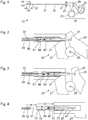
Die Handhabungseinrichtung umfasst einen ersten bzw. feststehenden Teil 21, einen zweiten bzw. bewegbaren Teil 22 und ein Rad 23. Der zweite Teil 22 ist mit dem ersten Teil 21 durch ein Gelenk derart verbunden, dass er relativ zum ersten Teil 21 um eine Schwenkachse 28 senkrecht zur Zeichenebene der
Der Schaft 30 umfasst ein proximales Ende 31, das mit der Handhabungseinrichtung 20 lösbar mechanisch gekoppelt ist, und ein distales Ende 32, das mit dem Werkzeug 40 lösbar mechanisch gekoppelt ist. Der Schaft 30 ist starr oder flexibel, gerade oder gekrümmt. Bei dem dargestellten Beispiel ist der Schaft 30 gerade und weist eine Längsachse 37 auf, zu der der Schaft 30 rotationssymmetrisch ist. Das proximale Ende 31 des Schafts 30 ist mit dem Rad 23 so mechanisch gekoppelt, dass mittels des Rads 23 der Schaft 30 und das Werkzeug 40 am distalen Ende 32 des Schafts 30 um die Längsachse 37 des Schafts 30 gedreht werden können.The
Das Werkzeug 40 weist ein proximales Ende 41, das mit dem distalen Ende 32 des Schafts 30 lösbar mechanisch gekoppelt ist, und ein distales Ende 42 auf. Am distalen Ende 42 weist das Werkzeug 40 ein feststehendes Maulteil 43 und ein schwenkbares Maulteil 44 auf. Das schwenkbare Maulteil 44 ist über eine in
In
Das proximale Ende 31 des Schafts 30 ist in einer Ausnehmung korrespondierender Gestalt im ersten Teil 21 der Handhabungseinrichtung 20 angeordnet. Der Schaft 30 bzw. dessen proximales Ende 31 kann in der Handhabungseinrichtung 20 bzw. dessen ersten Teil 21 lösbar mechanisch verriegelt sein, beispielsweise mittels einer in
Einem Rohr ähnlich weist der Schaft 30 ein Lumen auf, in dem die Übertragungseinrichtung 50 angeordnet ist. Das Lumen im Schaft 30 und die Übertragungseinrichtung 50 weisen jeweils im Wesentlichen eine kreiszylindrische Gestalt auf. Der Querschnitt des Lumens im Schaft 30 und der Querschnitt der Übertragungseinrichtung 50 sind so gewählt, dass die Übertragungseinrichtung 50 im Schaft 30 in einer Richtung parallel zur Längsachse 37 des Schafts 30 verschiebbar und um die Längsachse 37 rotierbar und dabei spiel- und reibungsarm geführt ist. Ein proximales Ende 51 der Übertragungseinrichtung 50 ist im Wesentlichen kugelförmig ausgebildet.Similar to a tube, the
Der Übertragungsadapter 60 ist überwiegend innerhalb des Schafts 30 nahe dessen proximalem Ende 31 angeordnet. Der Übertragungsadapter 60 umfasst eine erste Kupplung 61 an seinem proximalen Ende und eine zweite Kupplung 68 an seinem distalen Ende. Die erste Kupplung 61 weist im Wesentlichen die Gestalt einer Kugel auf und ist gelenkig mit dem zweiten Teil 22 der Handhabungseinrichtung 20 gekoppelt. In der in
Die zweite Kupplung 68 am distalen Ende des Übertragungsadapters 60 ist mit dem proximalen Ende 51 der Übertragungseinrichtung 50 mechanisch gekoppelt. Details sind unten mit Bezug auf die
Die Übertragungseinrichtung 50 und der Übertragungsadapter 60 sind parallel zur Längsachse 37 des Schafts 30 verschiebbar.
Zwischen dem proximalen Ende 51 der Übertragungseinrichtung 50 und der zweiten Kupplung 68 des Übertragungsadapters 60 besteht eine zwar lösbare, aber im ungelösten Zustand starre (insbesondere spielfreie oder spielarme) mechanische Verbindung. Deshalb wird jede Bewegung der ersten Kupplung 61 und jede Kraft auf die erste Kupplung 61 des Übertragungsadapters 60 in Richtung parallel zur Längsachse 37 des Schafts 30 auf die Übertragungseinrichtung 50 und von diesem zum distalen Ende des medizinischen Instruments 10 und zum Werkzeug 40 übertragen und umgekehrt.Between the
Das Ausführungsbeispiel der
In
Die
In den
Der Übertragungsadapter 60 umfasst einen Grundkörper 64 mit einem Widerlager 67, eine erste Greifbacke 81 und eine zweite Greifbacke 82. Die erste Greifbacke 81 und die zweite Greifbacke 82 bilden die zweite Kupplung 68 (vgl.
Der Schaft 30 bzw. der Schaftadapter 70 weisen zwei gegenüberliegende seitliche Öffnungen 38 auf. Die Greifbacken 81, 82 sind teilweise in den Öffnungen 38 angeordnet und liegen bei den in der
Wenn das proximale Ende 51 der Übertragungseinrichtung 50 nach proximal geschoben und dabei gegen die Greifbacken 81, 82 (insbesondere die angedeuteten schrägen Gleitflächen) gedrückt wird, werden die Greifbacken 81, 82 aus den in
Bei der in
Wenn die Übertragungseinrichtung 50 ausgehend von der in
Durch eine ausreichende Zugkraft auf die Übertragungseinrichtung 50 nach distal kann das proximale Ende 51 der Übertragungseinrichtung 50 aus der formschlüssigen Verbindung mit den Greifbacken 81, 82 gelöst werden. Dabei werden die Greifbacken 81, 82 gegen die durch die elastischen Elemente 87 ausgeübten Kräfte bzw. Momente (vorübergehend) in die in
In den Darstellungen der
Die seitlichen Öffnungen 38 im proximalen Bereich des Schafts 30 bzw. im Schaftadapter 70 sind wesentlich länger bzw. weisen eine in Richtung parallel zur Längsachse 37 des Schafts 30 (vgl.
Der in
Im Unterschied zu den oben anhand der
Bei dem Ausführungsbeispiel der
Das Ausführungsbeispiel in
Die
In
In der Darstellung in
Anders als in den
Bei den oben anhand der
Die in
Der Übertragungsadapter ist in einem Schaft 30, insbesondere in einem proximalen Bereich des Schafts 30 angeordnet. Das Lumen des Schafts 30, in dem eine Übertragungseinrichtung 50 angeordnet ist, ist zu einem Hohlraum erweitert, der auch den Übertragungsadapter aufnimmt. Das distale Ende 39 des Hohlraums ist ausgebildet, um ein Schwenken der Greifbacken 81, 82 nach außen zu ermöglichen, wenn der Übertragungsadapter mit dem Grundkörper 64 und den Greifbacken 81, 82 gegenüber der in
Nahe dem distalen Ende 39 des Hohlraums sind Kulissenführungen 83 angeordnet. Die Kulissenführungen 83 weisen jeweils einen im Wesentlichen geraden proximalen Abschnitt und einen gekrümmten distalen Abschnitt auf. An jeder Greifbacke 81, 82 ist nahe deren distalem Ende ein Stift 84 angeordnet, der in eine der Kulissenführungen 83 eingreift. Durch die Kulissenführungen 83 und die in die Kulissenführungen 83 eingreifenden Stifte 84 ist eine lineare Bewegung des Übertragungsadapters zwischen einer in
Das Kupplungsglied 90 ist um eine Rotationsachse 98 rotierbar, die im Wesentlichen parallel zur Längsachse einer mit dem Kupplungsglied 90 zu koppelnden Übertragungseinrichtung 50 ist. Das Kupplungsglied 90 weist eine Öffnung bzw. Ausnehmung 91 mit einem ersten Ende 92 und einem zweiten Ende 93 auf. Das erste Ende 92 weist einen Querschnitt (bezogen auf eine Ebene senkrecht zur Rotationsachse 98) auf, der an das proximale Ende 51 der Übertragungseinrichtung 50 angepasst ist. Das proximale Ende 51 der Übertragungseinrichtung 50 kann deshalb durch das erste Ende 92 der Ausnehmung 91 hindurchgeführt werden, wenn das erste Ende 92 der Ausnehmung 91 zum proximalen Ende 51 der Übertragungseinrichtung 50 so ausgerichtet ist, wie in
Das zweite Ende 92 der Ausnehmung 91 weist einen Querschnitt auf, der an den Querschnitt eines Halses 52 distal des proximalen Endes 51 der Übertragungseinrichtung 50 angepasst ist, Deshalb kann das rotierbare Kupplungsglied 90 um seine Rotationsachse 98 in die in
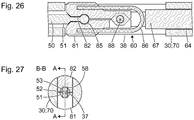
Die
Der Übertragungsadapter umfasst in einem Grundkörper 64 ein Kupplungsglied 90, das um eine Rotationsachse 98 senkrecht zur Schnittebene der
Die Ausnehmung umfasst eine im Wesentlichen kreiszylindrische Durchgangsbohrung 92, die an jedem Enden jeweils eine schlüssellochartige Erweiterung 93 in Richtung gegen den Uhrzeigersinn und parallel zur Schnittebene der
Bei der in
Das erfindungsgemäßen Ausführungsbeispiel der
In
Die
In
Das Halten der Übertragungseinrichtung 50 in der vorbestimmten rotatorischen Position bewirkt insbesondere eine Verriegelung einer Bajonettkupplung oder einer Schraubkupplung oder einer anderen lösbaren mechanischen Verbindung eines Werkzeugs 40 mit dem distalen Ende 32 eines Schafts 30 (vgl.
Beim Ausführungsbeispiel der
Das Halten der Übertragungseinrichtung 50 in der vorbestimmten rotatorischen Position bewirkt insbesondere eine Verriegelung einer Bajonettkupplung oder einer Schraubkupplung oder einer anderen lösbaren mechanischen Verbindung eines Werkzeugs 40 mit dem distalen Ende 32 eines Schafts 30 (vgl.
Der in
Anstelle eines U-förmigen elastischen Elements 86 kann ein andersartiges elastisches Element aus einem elastischen Material vorgesehen sein, das bei Auslenkung der Greifbacken 81, 82 aus ihren in
Das elastische Element 86 weist die gleiche Funktion auf wie die elastischen Elemente 87 der Ausführungsformen der
Die Ausführungsform der
Die Ausbildung der Abflachung 53 und der Ausnehmungen 58 an den Greifbacken 81, 82 gemäß
- 1010
- medizinisches Instrumentmedical instrument
- 2020
- Handhabungseinrichtunghandling device
- 2121
-
erster Teil der Handhabungseinrichtung 20first part of the handling
device 20 - 2222
-
zweiter Teil der Handhabungseinrichtung 20second part of the handling
device 20 - 2323
-
Rad an der Handhabungseinrichtung 20Wheel on the
handling device 20 - 2525
- Ausnehmungrecess
- 2626
-
Ausnehmung im zweiten Teil 22Recess in the
second part 22 - 2828
- Schwenkachse des zweiten Teils 22Pivot axis of the second part 22nd
- 3030
- Schaftshaft
- 3131
-
proximales Ende des Schafts 30proximal end of the
shaft 30 - 3232
-
distales Ende des Schafts 30distal end of the
shaft 30 - 3535
- distale Hülsedistal sleeve
- 3636
- proximale Hülseproximal sleeve
- 3737
-
Längsachse des Schafts 30Longitudinal axis of the
shaft 30 - 3838
-
seitliche Öffnung am proximalen Ende 31 des Schafts 30 oder des Schaftadapters 70lateral opening at the
proximal end 31 of theshaft 30 or theshaft adapter 70 - 3939
- distales Ende eines Hohlraumsdistal end of a cavity
- 4040
- WerkzeugTool
- 4141
-
proximales Ende des Werkzeugs 40proximal end of the
tool 40 - 4242
-
distales Ende des Werkzeugs 40distal end of the
tool 40 - 4343
-
feststehendes Maulteil des Werkzeugs 40fixed jaw part of the
tool 40 - 4444
-
schwenkbares Maulteil des Werkzeugs 40pivotable jaw part of the
tool 40 - 5050
- Übertragungseinrichtungtransmission equipment
- 5151
-
proximales Ende der Übertragungseinrichtung 50proximal end of the
transmission 50 - 5252
-
Hals distal des proximalen Endes 51 der Übertragungseinrichtung 50Neck distal to the
proximal end 51 of thetransfer device 50 - 5353
-
Abflachung distal des Halses 52Flattening distal to the
neck 52 - 5858
-
Ausnehmung an Greifbacke 81Recess on gripping
jaw 81 - 6060
- ÜbertragungsadapterCommunication adapter
- 6161
-
erste Kupplung des Übertragungsadapters 60first coupling of the
transmission adapter 60 - 6464
-
Grundkörper des Übertragungsadapters 60Basic body of the
transmission adapter 60 - 6565
- erster Holmfirst spar
- 6666
- zweiter Holmsecond spar
- 6767
-
Widerlager für elastische Abschnitte 87 der Greifbacken 81, 82Abutment for
elastic portions 87 of thejaws 81, 82nd - 6868
- zweite Kupplung des Übertragungsadapters 60second coupling of the transmission adapter 60th
- 6969
-
Nische im Grundkörper 64Niche in the
main body 64 - 7070
- SchaftadapterSocket adapter
- 7171
-
proximales Ende des Schaftadapters 70proximal end of the
shaft adapter 70 - 7272
-
distales Ende des Schaftadapters 70distal end of the
shaft adapter 70 - 7373
-
Ausnehmung am distalen Ende 72 des Schaftadapters 70Recess at the
distal end 72 of the shaft adapter 70th - 8181
- erste Greifbacke der zweiten Kupplung 68first jaw of the second clutch 68th
- 8282
- zweite Greifbacke der zweiten Kupplung 68second jaw of the second clutch 68th
- 8383
- Kulissenführunglink guide
- 8484
- Stiftpen
- 8585
-
konkaver Abschnitt an der ersten Greifbacke 81concave portion on the
first jaw 81 - 8686
- elastisches Elementelastic element
- 8787
- elastisches Elementelastic element
- 8888
-
Schwenkachse der Greifbacken 81, 82Pivot axis of the gripping
jaws - 8989
- Wellewave
- 9090
- rotierbares Kupplungsgliedrotatable coupling member
- 9191
- Ausnehmung im rotierbaren Kupplungsglied 90Recess in the rotatable coupling member 90th
- 9292
-
erstes Ende der Ausnehmung 91first end of the
recess 91 - 9393
-
zweites Ende der Ausnehmung 91second end of the
recess 91 - 9898
- Rotationsachse des rotierbaren Kupplungsglieds 90Rotation axis of the rotatable coupling member 90th
Claims (14)
- Transmission adapter (60) for a medical instrument (10) with a shank (30), a transmission device (50) movable in the shank (30), and a manipulating device (20) with a first part (21), which can be coupled mechanically rigidly to a proximal end (31) of the shank (30), and a second part (22), which is movable relative to the first part (21), wherein the transmission adapter (60) has:a first coupling element (61) for releasable mechanical coupling to the second part (22) of the manipulating device (20);a second coupling element (68) for releasable mechanical coupling to a proximal end (51) of the transmission device (50), characterized in that the second coupling element (68) is designed to transmit a torque to a transmission device (50) coupled to the second coupling element (68),wherein the second coupling element (68) has a shape that is not purely rotationally symmetrical with respect to the longitudinal axis of the transmission device (50) to be coupled to the second coupling element (68),wherein the second coupling element (68) defines a cavity of polygonal cross section (58), in order to receive a proximal end of the transmission device (50) of corresponding cross section (53).
- Transmission adapter (60) according to the preceding claim, in which the second coupling element (68) comprises a movable grip jaw (81, 82) for holding the proximal end (51) of the transmission device (50) with a form fit or force fit.
- Transmission adapter (60) according to Claim 2, also with:an elastic element (87), which is provided and designed to mechanically pretension the movable grip jaw (81, 82) to a position gripping the proximal end (51) of the transmission device (50).
- Transmission adapter (60) according to Claim 1, in which the second coupling element (68) has a rotatable coupling member (90), wherein the rotatable coupling member (90) is rotatable between a first position, in which a mechanical coupling to the proximal end (51) of the transmission device (50) can be produced and can be released, and a second position, in which a mechanical coupling to the proximal end (51) of the transmission device (50) is locked.
- Transmission adapter (60) according to one of the preceding claims, in which the second coupling element (68) is designed to be locked when the transmission adapter (60) is arranged in a manipulating device (20).
- Transmission adapter (60) according to one of the preceding claims, in which the first coupling element (61) of the transmission adapter (60) has a surface portion in the shape of a spherical surface.
- Shank (30) for a medical instrument (10), with:a proximal end (31) for coupling to a first part (21) of a manipulating device (20);a distal end (32) for coupling to a tool (40);a transmission adapter (60) according to one of the preceding claims, which is movable relative to the shank (30).
- Shank (30) according to the preceding claim, wherein the second coupling element (68) of the transmission adapter (60) is designed to transmit a torque to a transmission device (50) coupled to the second coupling element (68), in order to lock a releasable mechanical coupling of a tool (40) to the distal end (32) of the shank (30).
- Shank adapter (70) with:a proximal end (71) for coupling to a first part (21) of a manipulating device (20);a distal end (72) for coupling to a proximal end (31) of a shank (30);a transmission adapter (60) according to one of Claims 1 to 6, which is movable relative to the shank adapter (70).
- Shank (30) according to Claim 8 or shank adapter (70) according to Claim 9 with reference back to Claim 2, also with:a lateral opening (38), wherein the movable grip jaw (81, 82) is arranged at least partially in the lateral opening (38),wherein the movable grip jaw (81, 82) is designed to lie completely within the contour of the shank (30) or of the shank adapter (70) when a proximal end (51) of a transmission device (50) is held with a form fit by the movable grip jaw (81, 82), and to protrude beyond the contour of the shank (30) or of the shank adapter (70) when the transmission adapter (60) is uncoupled from a proximal end (51) of a transmission device (50).
- Medical instrument (10) with:a manipulating device (20) with a first part (21), and a second part (22) which is movable relative to the first part (21);a shank (30) with a proximal end (31), which can be coupled mechanically to the first part (21) of the manipulating device (20), and a distal end (32);a transmission device (50), movable in the shank (30), for transmitting at least either a force or a torque between the second part (21) of the manipulating device (20) and the distal end (32) of the shank (30);a transmission adapter (60) according to one of Claims 1 to 6.
- Medical instrument (10) according to the preceding claim, in which the transmission adapter (60) is a component part of a shank (30) according to Claim 7 or 8 or of a shank adapter (70) according to Claim 9 or 10.
- Medical instrument (10) according to either of Claims 11 and 12, in which
the transmission device (50), in an area provided for the mechanical coupling to the second coupling element (68) of the transmission adapter, has a cross section that is not rotationally symmetrical with respect to the longitudinal axis (37),
the second coupling element (68) of the transmission adapter (60) has a cross section that corresponds to the non-rotationally symmetrical cross section of the transmission device. - Medical instrument (10) according to one of Claims 11 to 13, with:a plurality of alternatively usable transmission devices (50) with differently designed proximal ends (51);a plurality of alternatively usable transmission adapters (60),wherein the first coupling elements (61) of all the transmission adapters (60) are identical and designed for releasable mechanical coupling to the second part (22) of the manipulating device (20),wherein the second coupling elements (68) of the plurality of transmission adapters (60) are designed differently,wherein each transmission adapter (60) has a second coupling element (68) which is designed for releasable mechanical coupling to a proximal end (51) of one of the transmission devices (50).
Applications Claiming Priority (1)
| Application Number | Priority Date | Filing Date | Title |
|---|---|---|---|
| DE102012022573.3A DE102012022573A1 (en) | 2012-11-20 | 2012-11-20 | Medical instrument |
Publications (2)
| Publication Number | Publication Date |
|---|---|
| EP2732778A1 EP2732778A1 (en) | 2014-05-21 |
| EP2732778B1 true EP2732778B1 (en) | 2018-03-14 |
Family
ID=49641492
Family Applications (1)
| Application Number | Title | Priority Date | Filing Date |
|---|---|---|---|
| EP13192615.6A Active EP2732778B1 (en) | 2012-11-20 | 2013-11-13 | Medical instrument |
Country Status (3)
| Country | Link |
|---|---|
| US (2) | US9782188B2 (en) |
| EP (1) | EP2732778B1 (en) |
| DE (1) | DE102012022573A1 (en) |
Families Citing this family (4)
| Publication number | Priority date | Publication date | Assignee | Title |
|---|---|---|---|---|
| DE102012022573A1 (en) * | 2012-11-20 | 2014-05-22 | Karl Storz Gmbh & Co. Kg | Medical instrument |
| CN103976774B (en) * | 2014-06-04 | 2016-08-17 | 李岱峰 | Medical surgical forceps |
| DE102015121481A1 (en) | 2015-12-10 | 2017-06-14 | Karl Storz Gmbh & Co. Kg | Coupling device for a dismountable medical instrument |
| DE102017109891A1 (en) * | 2017-05-09 | 2018-11-15 | Aesculap Ag | Surgical instrument with improved closure characteristics |
Family Cites Families (15)
| Publication number | Priority date | Publication date | Assignee | Title |
|---|---|---|---|---|
| WO1995002365A1 (en) * | 1993-07-17 | 1995-01-26 | Gerhard Schad | Surgical instrument |
| DE19505032A1 (en) * | 1994-02-18 | 1995-08-24 | Harold Nowosad | Surgical instrument with tubular shaft |
| US5810879A (en) * | 1997-02-27 | 1998-09-22 | Microline, Inc. | Laparoscopic instrument |
| DE19852682C2 (en) * | 1998-11-16 | 2000-11-16 | Robert Mueller | Surgical splint instrument |
| US6077290A (en) * | 1999-09-10 | 2000-06-20 | Tnco, Incorporated | Endoscopic instrument with removable front end |
| US7476237B2 (en) * | 2003-02-27 | 2009-01-13 | Olympus Corporation | Surgical instrument |
| DE102004025041A1 (en) * | 2004-05-18 | 2005-12-08 | Ewald Hensler | Laparoscopy pliers for surgical operation has slider provided with a clamping device which contacts the control rod for the cutting element |
| EP1876979B1 (en) * | 2005-04-29 | 2011-10-05 | Bovie Medical Corporation | Forceps for performing endoscopic or arthrocsopic surgery |
| US20080004656A1 (en) * | 2006-04-28 | 2008-01-03 | Bovie Medical Corporation | Surgical instrument with detachable tool assembly |
| DE102006038515A1 (en) * | 2006-08-17 | 2008-02-21 | Karl Storz Gmbh & Co. Kg | Medical tubular shaft instrument |
| DE102007021658A1 (en) * | 2007-05-04 | 2008-11-06 | Karl Storz Gmbh & Co. Kg | Dismountable medical forceps system |
| AU2007221906B1 (en) * | 2007-10-09 | 2008-10-23 | John Silady | Control System for A Grasping Instrument |
| DE102011007121A1 (en) * | 2011-04-11 | 2012-10-11 | Karl Storz Gmbh & Co. Kg | Handling device for a micro-invasive-surgical instrument |
| DE102012200073A1 (en) * | 2012-01-04 | 2013-07-04 | Karl Storz Gmbh & Co. Kg | Medical instrument |
| DE102012022573A1 (en) * | 2012-11-20 | 2014-05-22 | Karl Storz Gmbh & Co. Kg | Medical instrument |
-
2012
- 2012-11-20 DE DE102012022573.3A patent/DE102012022573A1/en not_active Withdrawn
-
2013
- 2013-11-13 EP EP13192615.6A patent/EP2732778B1/en active Active
- 2013-11-20 US US14/085,306 patent/US9782188B2/en active Active
-
2017
- 2017-09-07 US US15/698,155 patent/US10433860B2/en active Active
Non-Patent Citations (1)
| Title |
|---|
| None * |
Also Published As
| Publication number | Publication date |
|---|---|
| DE102012022573A1 (en) | 2014-05-22 |
| US20140155933A1 (en) | 2014-06-05 |
| US20170367722A1 (en) | 2017-12-28 |
| US9782188B2 (en) | 2017-10-10 |
| EP2732778A1 (en) | 2014-05-21 |
| US10433860B2 (en) | 2019-10-08 |
Similar Documents
| Publication | Publication Date | Title |
|---|---|---|
| EP2612609B1 (en) | Medical instrument | |
| EP2510888B1 (en) | Handling device for a micro-invasive surgical instrument | |
| EP2653110B1 (en) | Medical instrument with articulatable shaft | |
| EP2666420B1 (en) | Medical instrument with a shaft with a flexible section and a controlled bendable section | |
| EP2561816B1 (en) | Tool for a micro-invasive surgical instrument | |
| EP2510887B1 (en) | Tool for a micro-surgical instrument | |
| EP0860148A2 (en) | Bayonet coupling for the releasable connection of two tubular-shaft instruments or two parts of an instrument | |
| EP2510889B1 (en) | Handling device for a micro-invasive surgical instrument | |
| EP2653120B1 (en) | Handle for a medical instrument | |
| EP2732778B1 (en) | Medical instrument | |
| DE102014102606A1 (en) | Microsurgical holding and / or cutting instrument | |
| EP3351191B1 (en) | Surgical instrument, in particular for neurosurgery | |
| DE10327655A1 (en) | Medical instrument | |
| EP2613726B1 (en) | Surgical instrument | |
| EP1629785A2 (en) | Medical forceps | |
| EP3250133B1 (en) | Shaft instrument for surgical purposes | |
| DE202011000828U1 (en) | Surgical instrument shaft and surgical instrument | |
| EP2258285B1 (en) | Medical punch | |
| EP2792319B1 (en) | Actuating element and rocker pair for an actuating element | |
| DE202007000427U1 (en) | Surgical operating handle for a surgical instrument, especially an endoscopic instrument, comprises a handle part positioned on the operating handle | |
| DE102019129462A1 (en) | Medical instrument that can be dismantled | |
| EP3266394B1 (en) | Surgical instrument with a locking device | |
| DE102011001890A1 (en) | Shaft for micro-surgical instrument for fixing e.g. scissors, has shaft unit provided with proximal end, where handlebars of instrument and force transmitting and tool elements are pivotable and handlebars and pin are integrally formed | |
| EP3300675A1 (en) | Component for a medical instrument and medical instrument | |
| DE19652163C2 (en) | Surgical instrument |
Legal Events
| Date | Code | Title | Description |
|---|---|---|---|
| PUAI | Public reference made under article 153(3) epc to a published international application that has entered the european phase |
Free format text: ORIGINAL CODE: 0009012 |
|
| 17P | Request for examination filed |
Effective date: 20131113 |
|
| AK | Designated contracting states |
Kind code of ref document: A1 Designated state(s): AL AT BE BG CH CY CZ DE DK EE ES FI FR GB GR HR HU IE IS IT LI LT LU LV MC MK MT NL NO PL PT RO RS SE SI SK SM TR |
|
| R17P | Request for examination filed (corrected) |
Effective date: 20141121 |
|
| RBV | Designated contracting states (corrected) |
Designated state(s): AL AT BE BG CH CY CZ DE DK EE ES FI FR GB GR HR HU IE IS IT LI LT LU LV MC MK MT NL NO PL PT RO RS SE SI SK SM TR |
|
| GRAP | Despatch of communication of intention to grant a patent |
Free format text: ORIGINAL CODE: EPIDOSNIGR1 |
|
| RIC1 | Information provided on ipc code assigned before grant |
Ipc: A61B 17/29 20060101AFI20171129BHEP Ipc: A61B 17/00 20060101ALN20171129BHEP |
|
| INTG | Intention to grant announced |
Effective date: 20171215 |
|
| RAP1 | Party data changed (applicant data changed or rights of an application transferred) |
Owner name: KARL STORZ SE & CO. KG |
|
| RIC1 | Information provided on ipc code assigned before grant |
Ipc: A61B 17/00 20060101ALN20171206BHEP Ipc: A61B 17/29 20060101AFI20171206BHEP |
|
| GRAS | Grant fee paid |
Free format text: ORIGINAL CODE: EPIDOSNIGR3 |
|
| GRAA | (expected) grant |
Free format text: ORIGINAL CODE: 0009210 |
|
| AK | Designated contracting states |
Kind code of ref document: B1 Designated state(s): AL AT BE BG CH CY CZ DE DK EE ES FI FR GB GR HR HU IE IS IT LI LT LU LV MC MK MT NL NO PL PT RO RS SE SI SK SM TR |
|
| REG | Reference to a national code |
Ref country code: GB Ref legal event code: FG4D Free format text: NOT ENGLISH |
|
| REG | Reference to a national code |
Ref country code: CH Ref legal event code: EP Ref country code: AT Ref legal event code: REF Ref document number: 978084 Country of ref document: AT Kind code of ref document: T Effective date: 20180315 |
|
| REG | Reference to a national code |
Ref country code: IE Ref legal event code: FG4D Free format text: LANGUAGE OF EP DOCUMENT: GERMAN |
|
| REG | Reference to a national code |
Ref country code: DE Ref legal event code: R096 Ref document number: 502013009642 Country of ref document: DE |
|
| REG | Reference to a national code |
Ref country code: NL Ref legal event code: MP Effective date: 20180314 |
|
| REG | Reference to a national code |
Ref country code: LT Ref legal event code: MG4D |
|
| PG25 | Lapsed in a contracting state [announced via postgrant information from national office to epo] |
Ref country code: ES Free format text: LAPSE BECAUSE OF FAILURE TO SUBMIT A TRANSLATION OF THE DESCRIPTION OR TO PAY THE FEE WITHIN THE PRESCRIBED TIME-LIMIT Effective date: 20180314 Ref country code: CY Free format text: LAPSE BECAUSE OF FAILURE TO SUBMIT A TRANSLATION OF THE DESCRIPTION OR TO PAY THE FEE WITHIN THE PRESCRIBED TIME-LIMIT Effective date: 20180314 Ref country code: FI Free format text: LAPSE BECAUSE OF FAILURE TO SUBMIT A TRANSLATION OF THE DESCRIPTION OR TO PAY THE FEE WITHIN THE PRESCRIBED TIME-LIMIT Effective date: 20180314 Ref country code: NO Free format text: LAPSE BECAUSE OF FAILURE TO SUBMIT A TRANSLATION OF THE DESCRIPTION OR TO PAY THE FEE WITHIN THE PRESCRIBED TIME-LIMIT Effective date: 20180614 Ref country code: LT Free format text: LAPSE BECAUSE OF FAILURE TO SUBMIT A TRANSLATION OF THE DESCRIPTION OR TO PAY THE FEE WITHIN THE PRESCRIBED TIME-LIMIT Effective date: 20180314 Ref country code: HR Free format text: LAPSE BECAUSE OF FAILURE TO SUBMIT A TRANSLATION OF THE DESCRIPTION OR TO PAY THE FEE WITHIN THE PRESCRIBED TIME-LIMIT Effective date: 20180314 |
|
| PG25 | Lapsed in a contracting state [announced via postgrant information from national office to epo] |
Ref country code: BG Free format text: LAPSE BECAUSE OF FAILURE TO SUBMIT A TRANSLATION OF THE DESCRIPTION OR TO PAY THE FEE WITHIN THE PRESCRIBED TIME-LIMIT Effective date: 20180614 Ref country code: RS Free format text: LAPSE BECAUSE OF FAILURE TO SUBMIT A TRANSLATION OF THE DESCRIPTION OR TO PAY THE FEE WITHIN THE PRESCRIBED TIME-LIMIT Effective date: 20180314 Ref country code: SE Free format text: LAPSE BECAUSE OF FAILURE TO SUBMIT A TRANSLATION OF THE DESCRIPTION OR TO PAY THE FEE WITHIN THE PRESCRIBED TIME-LIMIT Effective date: 20180314 Ref country code: GR Free format text: LAPSE BECAUSE OF FAILURE TO SUBMIT A TRANSLATION OF THE DESCRIPTION OR TO PAY THE FEE WITHIN THE PRESCRIBED TIME-LIMIT Effective date: 20180615 Ref country code: LV Free format text: LAPSE BECAUSE OF FAILURE TO SUBMIT A TRANSLATION OF THE DESCRIPTION OR TO PAY THE FEE WITHIN THE PRESCRIBED TIME-LIMIT Effective date: 20180314 |
|
| PG25 | Lapsed in a contracting state [announced via postgrant information from national office to epo] |
Ref country code: MT Free format text: LAPSE BECAUSE OF FAILURE TO SUBMIT A TRANSLATION OF THE DESCRIPTION OR TO PAY THE FEE WITHIN THE PRESCRIBED TIME-LIMIT Effective date: 20180314 |
|
| REG | Reference to a national code |
Ref country code: FR Ref legal event code: PLFP Year of fee payment: 6 |
|
| PG25 | Lapsed in a contracting state [announced via postgrant information from national office to epo] |
Ref country code: RO Free format text: LAPSE BECAUSE OF FAILURE TO SUBMIT A TRANSLATION OF THE DESCRIPTION OR TO PAY THE FEE WITHIN THE PRESCRIBED TIME-LIMIT Effective date: 20180314 Ref country code: PL Free format text: LAPSE BECAUSE OF FAILURE TO SUBMIT A TRANSLATION OF THE DESCRIPTION OR TO PAY THE FEE WITHIN THE PRESCRIBED TIME-LIMIT Effective date: 20180314 Ref country code: NL Free format text: LAPSE BECAUSE OF FAILURE TO SUBMIT A TRANSLATION OF THE DESCRIPTION OR TO PAY THE FEE WITHIN THE PRESCRIBED TIME-LIMIT Effective date: 20180314 Ref country code: EE Free format text: LAPSE BECAUSE OF FAILURE TO SUBMIT A TRANSLATION OF THE DESCRIPTION OR TO PAY THE FEE WITHIN THE PRESCRIBED TIME-LIMIT Effective date: 20180314 Ref country code: AL Free format text: LAPSE BECAUSE OF FAILURE TO SUBMIT A TRANSLATION OF THE DESCRIPTION OR TO PAY THE FEE WITHIN THE PRESCRIBED TIME-LIMIT Effective date: 20180314 |
|
| PG25 | Lapsed in a contracting state [announced via postgrant information from national office to epo] |
Ref country code: SM Free format text: LAPSE BECAUSE OF FAILURE TO SUBMIT A TRANSLATION OF THE DESCRIPTION OR TO PAY THE FEE WITHIN THE PRESCRIBED TIME-LIMIT Effective date: 20180314 Ref country code: CZ Free format text: LAPSE BECAUSE OF FAILURE TO SUBMIT A TRANSLATION OF THE DESCRIPTION OR TO PAY THE FEE WITHIN THE PRESCRIBED TIME-LIMIT Effective date: 20180314 Ref country code: SK Free format text: LAPSE BECAUSE OF FAILURE TO SUBMIT A TRANSLATION OF THE DESCRIPTION OR TO PAY THE FEE WITHIN THE PRESCRIBED TIME-LIMIT Effective date: 20180314 |
|
| REG | Reference to a national code |
Ref country code: DE Ref legal event code: R097 Ref document number: 502013009642 Country of ref document: DE |
|
| PG25 | Lapsed in a contracting state [announced via postgrant information from national office to epo] |
Ref country code: PT Free format text: LAPSE BECAUSE OF FAILURE TO SUBMIT A TRANSLATION OF THE DESCRIPTION OR TO PAY THE FEE WITHIN THE PRESCRIBED TIME-LIMIT Effective date: 20180716 |
|
| PLBE | No opposition filed within time limit |
Free format text: ORIGINAL CODE: 0009261 |
|
| STAA | Information on the status of an ep patent application or granted ep patent |
Free format text: STATUS: NO OPPOSITION FILED WITHIN TIME LIMIT |
|
| PG25 | Lapsed in a contracting state [announced via postgrant information from national office to epo] |
Ref country code: DK Free format text: LAPSE BECAUSE OF FAILURE TO SUBMIT A TRANSLATION OF THE DESCRIPTION OR TO PAY THE FEE WITHIN THE PRESCRIBED TIME-LIMIT Effective date: 20180314 |
|
| 26N | No opposition filed |
Effective date: 20181217 |
|
| PG25 | Lapsed in a contracting state [announced via postgrant information from national office to epo] |
Ref country code: SI Free format text: LAPSE BECAUSE OF FAILURE TO SUBMIT A TRANSLATION OF THE DESCRIPTION OR TO PAY THE FEE WITHIN THE PRESCRIBED TIME-LIMIT Effective date: 20180314 |
|
| REG | Reference to a national code |
Ref country code: CH Ref legal event code: PL |
|
| PG25 | Lapsed in a contracting state [announced via postgrant information from national office to epo] |
Ref country code: MC Free format text: LAPSE BECAUSE OF FAILURE TO SUBMIT A TRANSLATION OF THE DESCRIPTION OR TO PAY THE FEE WITHIN THE PRESCRIBED TIME-LIMIT Effective date: 20180314 Ref country code: LU Free format text: LAPSE BECAUSE OF NON-PAYMENT OF DUE FEES Effective date: 20181113 |
|
| REG | Reference to a national code |
Ref country code: BE Ref legal event code: MM Effective date: 20181130 |
|
| REG | Reference to a national code |
Ref country code: IE Ref legal event code: MM4A |
|
| PG25 | Lapsed in a contracting state [announced via postgrant information from national office to epo] |
Ref country code: CH Free format text: LAPSE BECAUSE OF NON-PAYMENT OF DUE FEES Effective date: 20181130 Ref country code: LI Free format text: LAPSE BECAUSE OF NON-PAYMENT OF DUE FEES Effective date: 20181130 |
|
| PG25 | Lapsed in a contracting state [announced via postgrant information from national office to epo] |
Ref country code: IE Free format text: LAPSE BECAUSE OF NON-PAYMENT OF DUE FEES Effective date: 20181113 |
|
| PG25 | Lapsed in a contracting state [announced via postgrant information from national office to epo] |
Ref country code: BE Free format text: LAPSE BECAUSE OF NON-PAYMENT OF DUE FEES Effective date: 20181130 |
|
| REG | Reference to a national code |
Ref country code: AT Ref legal event code: MM01 Ref document number: 978084 Country of ref document: AT Kind code of ref document: T Effective date: 20181113 |
|
| PG25 | Lapsed in a contracting state [announced via postgrant information from national office to epo] |
Ref country code: AT Free format text: LAPSE BECAUSE OF NON-PAYMENT OF DUE FEES Effective date: 20181113 |
|
| PG25 | Lapsed in a contracting state [announced via postgrant information from national office to epo] |
Ref country code: TR Free format text: LAPSE BECAUSE OF FAILURE TO SUBMIT A TRANSLATION OF THE DESCRIPTION OR TO PAY THE FEE WITHIN THE PRESCRIBED TIME-LIMIT Effective date: 20180314 |
|
| PG25 | Lapsed in a contracting state [announced via postgrant information from national office to epo] |
Ref country code: HU Free format text: LAPSE BECAUSE OF FAILURE TO SUBMIT A TRANSLATION OF THE DESCRIPTION OR TO PAY THE FEE WITHIN THE PRESCRIBED TIME-LIMIT; INVALID AB INITIO Effective date: 20131113 Ref country code: MK Free format text: LAPSE BECAUSE OF NON-PAYMENT OF DUE FEES Effective date: 20180314 |
|
| PG25 | Lapsed in a contracting state [announced via postgrant information from national office to epo] |
Ref country code: IS Free format text: LAPSE BECAUSE OF FAILURE TO SUBMIT A TRANSLATION OF THE DESCRIPTION OR TO PAY THE FEE WITHIN THE PRESCRIBED TIME-LIMIT Effective date: 20180714 |
|
| P01 | Opt-out of the competence of the unified patent court (upc) registered |
Effective date: 20230527 |
|
| PGFP | Annual fee paid to national office [announced via postgrant information from national office to epo] |
Ref country code: GB Payment date: 20231019 Year of fee payment: 11 |
|
| PGFP | Annual fee paid to national office [announced via postgrant information from national office to epo] |
Ref country code: IT Payment date: 20231019 Year of fee payment: 11 Ref country code: FR Payment date: 20231020 Year of fee payment: 11 Ref country code: DE Payment date: 20231019 Year of fee payment: 11 |