EP3351191B1 - Surgical instrument, in particular for neurosurgery - Google Patents
Surgical instrument, in particular for neurosurgery Download PDFInfo
- Publication number
- EP3351191B1 EP3351191B1 EP18152174.1A EP18152174A EP3351191B1 EP 3351191 B1 EP3351191 B1 EP 3351191B1 EP 18152174 A EP18152174 A EP 18152174A EP 3351191 B1 EP3351191 B1 EP 3351191B1
- Authority
- EP
- European Patent Office
- Prior art keywords
- instrument
- shaft
- guideway
- pull element
- pull
- Prior art date
- Legal status (The legal status is an assumption and is not a legal conclusion. Google has not performed a legal analysis and makes no representation as to the accuracy of the status listed.)
- Active
Links
- 230000007246 mechanism Effects 0.000 claims description 70
- 239000012636 effector Substances 0.000 claims description 61
- 230000008878 coupling Effects 0.000 claims description 49
- 238000010168 coupling process Methods 0.000 claims description 49
- 238000005859 coupling reaction Methods 0.000 claims description 49
- 238000005452 bending Methods 0.000 claims description 9
- 229910001000 nickel titanium Inorganic materials 0.000 claims description 6
- HLXZNVUGXRDIFK-UHFFFAOYSA-N nickel titanium Chemical compound [Ti].[Ti].[Ti].[Ti].[Ti].[Ti].[Ti].[Ti].[Ti].[Ti].[Ti].[Ni].[Ni].[Ni].[Ni].[Ni].[Ni].[Ni].[Ni].[Ni].[Ni].[Ni].[Ni].[Ni].[Ni] HLXZNVUGXRDIFK-UHFFFAOYSA-N 0.000 claims description 6
- 229910045601 alloy Inorganic materials 0.000 claims description 5
- 239000000956 alloy Substances 0.000 claims description 5
- 229920001971 elastomer Polymers 0.000 claims description 2
- 239000000806 elastomer Substances 0.000 claims description 2
- 238000001356 surgical procedure Methods 0.000 description 13
- 210000004556 brain Anatomy 0.000 description 10
- 230000008901 benefit Effects 0.000 description 8
- 230000000694 effects Effects 0.000 description 6
- 230000002349 favourable effect Effects 0.000 description 5
- 230000036316 preload Effects 0.000 description 5
- 239000013013 elastic material Substances 0.000 description 4
- 239000000463 material Substances 0.000 description 3
- 230000009467 reduction Effects 0.000 description 3
- 230000002829 reductive effect Effects 0.000 description 3
- 210000003625 skull Anatomy 0.000 description 3
- 241000050051 Chelone glabra Species 0.000 description 2
- 102000004315 Forkhead Transcription Factors Human genes 0.000 description 2
- 108090000852 Forkhead Transcription Factors Proteins 0.000 description 2
- 238000001574 biopsy Methods 0.000 description 2
- 230000015271 coagulation Effects 0.000 description 2
- 238000005345 coagulation Methods 0.000 description 2
- 230000006870 function Effects 0.000 description 2
- 238000009434 installation Methods 0.000 description 2
- 238000005304 joining Methods 0.000 description 2
- 238000002357 laparoscopic surgery Methods 0.000 description 2
- 238000004519 manufacturing process Methods 0.000 description 2
- 230000036961 partial effect Effects 0.000 description 2
- 239000013641 positive control Substances 0.000 description 2
- 230000035945 sensitivity Effects 0.000 description 2
- 239000010935 stainless steel Substances 0.000 description 2
- 229910001220 stainless steel Inorganic materials 0.000 description 2
- 210000001519 tissue Anatomy 0.000 description 2
- 206010067482 No adverse event Diseases 0.000 description 1
- 229910000639 Spring steel Inorganic materials 0.000 description 1
- 230000009471 action Effects 0.000 description 1
- 230000002411 adverse Effects 0.000 description 1
- 230000005540 biological transmission Effects 0.000 description 1
- 238000004140 cleaning Methods 0.000 description 1
- 230000006835 compression Effects 0.000 description 1
- 238000007906 compression Methods 0.000 description 1
- 238000010276 construction Methods 0.000 description 1
- 238000005520 cutting process Methods 0.000 description 1
- 238000006073 displacement reaction Methods 0.000 description 1
- 238000005553 drilling Methods 0.000 description 1
- 230000005489 elastic deformation Effects 0.000 description 1
- 238000002674 endoscopic surgery Methods 0.000 description 1
- 239000004744 fabric Substances 0.000 description 1
- 230000005484 gravity Effects 0.000 description 1
- 208000014674 injury Diseases 0.000 description 1
- 230000003993 interaction Effects 0.000 description 1
- 238000002955 isolation Methods 0.000 description 1
- 238000012423 maintenance Methods 0.000 description 1
- 239000007769 metal material Substances 0.000 description 1
- 238000002324 minimally invasive surgery Methods 0.000 description 1
- 230000007935 neutral effect Effects 0.000 description 1
- 230000008439 repair process Effects 0.000 description 1
- 230000002441 reversible effect Effects 0.000 description 1
- 230000028327 secretion Effects 0.000 description 1
- 229910001285 shape-memory alloy Inorganic materials 0.000 description 1
- 230000008733 trauma Effects 0.000 description 1
- 230000003313 weakening effect Effects 0.000 description 1
Images


Classifications
-
- A—HUMAN NECESSITIES
- A61—MEDICAL OR VETERINARY SCIENCE; HYGIENE
- A61B—DIAGNOSIS; SURGERY; IDENTIFICATION
- A61B34/00—Computer-aided surgery; Manipulators or robots specially adapted for use in surgery
- A61B34/70—Manipulators specially adapted for use in surgery
- A61B34/71—Manipulators operated by drive cable mechanisms
-
- A—HUMAN NECESSITIES
- A61—MEDICAL OR VETERINARY SCIENCE; HYGIENE
- A61B—DIAGNOSIS; SURGERY; IDENTIFICATION
- A61B10/00—Other methods or instruments for diagnosis, e.g. instruments for taking a cell sample, for biopsy, for vaccination diagnosis; Sex determination; Ovulation-period determination; Throat striking implements
- A61B10/02—Instruments for taking cell samples or for biopsy
- A61B10/06—Biopsy forceps, e.g. with cup-shaped jaws
-
- A—HUMAN NECESSITIES
- A61—MEDICAL OR VETERINARY SCIENCE; HYGIENE
- A61B—DIAGNOSIS; SURGERY; IDENTIFICATION
- A61B17/00—Surgical instruments, devices or methods, e.g. tourniquets
- A61B17/28—Surgical forceps
- A61B17/29—Forceps for use in minimally invasive surgery
-
- A—HUMAN NECESSITIES
- A61—MEDICAL OR VETERINARY SCIENCE; HYGIENE
- A61B—DIAGNOSIS; SURGERY; IDENTIFICATION
- A61B17/00—Surgical instruments, devices or methods, e.g. tourniquets
- A61B17/28—Surgical forceps
- A61B17/29—Forceps for use in minimally invasive surgery
- A61B17/2909—Handles
-
- A—HUMAN NECESSITIES
- A61—MEDICAL OR VETERINARY SCIENCE; HYGIENE
- A61B—DIAGNOSIS; SURGERY; IDENTIFICATION
- A61B17/00—Surgical instruments, devices or methods, e.g. tourniquets
- A61B17/32—Surgical cutting instruments
- A61B17/3201—Scissors
-
- A—HUMAN NECESSITIES
- A61—MEDICAL OR VETERINARY SCIENCE; HYGIENE
- A61B—DIAGNOSIS; SURGERY; IDENTIFICATION
- A61B17/00—Surgical instruments, devices or methods, e.g. tourniquets
- A61B17/00234—Surgical instruments, devices or methods, e.g. tourniquets for minimally invasive surgery
- A61B2017/00292—Surgical instruments, devices or methods, e.g. tourniquets for minimally invasive surgery mounted on or guided by flexible, e.g. catheter-like, means
- A61B2017/003—Steerable
- A61B2017/00305—Constructional details of the flexible means
- A61B2017/00314—Separate linked members
-
- A—HUMAN NECESSITIES
- A61—MEDICAL OR VETERINARY SCIENCE; HYGIENE
- A61B—DIAGNOSIS; SURGERY; IDENTIFICATION
- A61B17/00—Surgical instruments, devices or methods, e.g. tourniquets
- A61B17/00234—Surgical instruments, devices or methods, e.g. tourniquets for minimally invasive surgery
- A61B2017/00292—Surgical instruments, devices or methods, e.g. tourniquets for minimally invasive surgery mounted on or guided by flexible, e.g. catheter-like, means
- A61B2017/003—Steerable
- A61B2017/00318—Steering mechanisms
- A61B2017/00323—Cables or rods
- A61B2017/00327—Cables or rods with actuating members moving in opposite directions
-
- A—HUMAN NECESSITIES
- A61—MEDICAL OR VETERINARY SCIENCE; HYGIENE
- A61B—DIAGNOSIS; SURGERY; IDENTIFICATION
- A61B17/00—Surgical instruments, devices or methods, e.g. tourniquets
- A61B2017/0046—Surgical instruments, devices or methods, e.g. tourniquets with a releasable handle; with handle and operating part separable
-
- A—HUMAN NECESSITIES
- A61—MEDICAL OR VETERINARY SCIENCE; HYGIENE
- A61B—DIAGNOSIS; SURGERY; IDENTIFICATION
- A61B17/00—Surgical instruments, devices or methods, e.g. tourniquets
- A61B17/28—Surgical forceps
- A61B2017/2808—Clamp, e.g. towel clamp
-
- A—HUMAN NECESSITIES
- A61—MEDICAL OR VETERINARY SCIENCE; HYGIENE
- A61B—DIAGNOSIS; SURGERY; IDENTIFICATION
- A61B17/00—Surgical instruments, devices or methods, e.g. tourniquets
- A61B17/28—Surgical forceps
- A61B17/29—Forceps for use in minimally invasive surgery
- A61B2017/2901—Details of shaft
- A61B2017/2902—Details of shaft characterized by features of the actuating rod
-
- A—HUMAN NECESSITIES
- A61—MEDICAL OR VETERINARY SCIENCE; HYGIENE
- A61B—DIAGNOSIS; SURGERY; IDENTIFICATION
- A61B17/00—Surgical instruments, devices or methods, e.g. tourniquets
- A61B17/28—Surgical forceps
- A61B17/29—Forceps for use in minimally invasive surgery
- A61B17/2909—Handles
- A61B2017/2912—Handles transmission of forces to actuating rod or piston
- A61B2017/2913—Handles transmission of forces to actuating rod or piston cams or guiding means
- A61B2017/2915—Handles transmission of forces to actuating rod or piston cams or guiding means arcuate shaped guiding means
-
- A—HUMAN NECESSITIES
- A61—MEDICAL OR VETERINARY SCIENCE; HYGIENE
- A61B—DIAGNOSIS; SURGERY; IDENTIFICATION
- A61B17/00—Surgical instruments, devices or methods, e.g. tourniquets
- A61B17/28—Surgical forceps
- A61B17/29—Forceps for use in minimally invasive surgery
- A61B17/2909—Handles
- A61B2017/2912—Handles transmission of forces to actuating rod or piston
- A61B2017/2913—Handles transmission of forces to actuating rod or piston cams or guiding means
- A61B2017/2916—Handles transmission of forces to actuating rod or piston cams or guiding means pins in guiding slots
-
- A—HUMAN NECESSITIES
- A61—MEDICAL OR VETERINARY SCIENCE; HYGIENE
- A61B—DIAGNOSIS; SURGERY; IDENTIFICATION
- A61B17/00—Surgical instruments, devices or methods, e.g. tourniquets
- A61B17/28—Surgical forceps
- A61B17/29—Forceps for use in minimally invasive surgery
- A61B17/2909—Handles
- A61B2017/2912—Handles transmission of forces to actuating rod or piston
- A61B2017/2919—Handles transmission of forces to actuating rod or piston details of linkages or pivot points
-
- A—HUMAN NECESSITIES
- A61—MEDICAL OR VETERINARY SCIENCE; HYGIENE
- A61B—DIAGNOSIS; SURGERY; IDENTIFICATION
- A61B17/00—Surgical instruments, devices or methods, e.g. tourniquets
- A61B17/28—Surgical forceps
- A61B17/29—Forceps for use in minimally invasive surgery
- A61B17/2909—Handles
- A61B2017/2925—Pistol grips
-
- A—HUMAN NECESSITIES
- A61—MEDICAL OR VETERINARY SCIENCE; HYGIENE
- A61B—DIAGNOSIS; SURGERY; IDENTIFICATION
- A61B17/00—Surgical instruments, devices or methods, e.g. tourniquets
- A61B17/28—Surgical forceps
- A61B17/29—Forceps for use in minimally invasive surgery
- A61B2017/2926—Details of heads or jaws
- A61B2017/2932—Transmission of forces to jaw members
- A61B2017/2933—Transmission of forces to jaw members camming or guiding means
- A61B2017/2934—Transmission of forces to jaw members camming or guiding means arcuate shaped guiding means
-
- A—HUMAN NECESSITIES
- A61—MEDICAL OR VETERINARY SCIENCE; HYGIENE
- A61B—DIAGNOSIS; SURGERY; IDENTIFICATION
- A61B17/00—Surgical instruments, devices or methods, e.g. tourniquets
- A61B17/28—Surgical forceps
- A61B17/29—Forceps for use in minimally invasive surgery
- A61B2017/2926—Details of heads or jaws
- A61B2017/2932—Transmission of forces to jaw members
- A61B2017/2933—Transmission of forces to jaw members camming or guiding means
- A61B2017/2936—Pins in guiding slots
-
- A—HUMAN NECESSITIES
- A61—MEDICAL OR VETERINARY SCIENCE; HYGIENE
- A61B—DIAGNOSIS; SURGERY; IDENTIFICATION
- A61B17/00—Surgical instruments, devices or methods, e.g. tourniquets
- A61B17/30—Surgical pincettes without pivotal connections
- A61B2017/305—Tweezer like handles with tubular extensions, inner slidable actuating members and distal tools, e.g. microsurgical instruments
-
- A—HUMAN NECESSITIES
- A61—MEDICAL OR VETERINARY SCIENCE; HYGIENE
- A61B—DIAGNOSIS; SURGERY; IDENTIFICATION
- A61B17/00—Surgical instruments, devices or methods, e.g. tourniquets
- A61B17/32—Surgical cutting instruments
- A61B2017/320004—Surgical cutting instruments abrasive
- A61B2017/320008—Scrapers
-
- A—HUMAN NECESSITIES
- A61—MEDICAL OR VETERINARY SCIENCE; HYGIENE
- A61B—DIAGNOSIS; SURGERY; IDENTIFICATION
- A61B18/00—Surgical instruments, devices or methods for transferring non-mechanical forms of energy to or from the body
- A61B2018/00571—Surgical instruments, devices or methods for transferring non-mechanical forms of energy to or from the body for achieving a particular surgical effect
- A61B2018/00589—Coagulation
-
- A—HUMAN NECESSITIES
- A61—MEDICAL OR VETERINARY SCIENCE; HYGIENE
- A61B—DIAGNOSIS; SURGERY; IDENTIFICATION
- A61B90/00—Instruments, implements or accessories specially adapted for surgery or diagnosis and not covered by any of the groups A61B1/00 - A61B50/00, e.g. for luxation treatment or for protecting wound edges
- A61B90/08—Accessories or related features not otherwise provided for
- A61B2090/0813—Accessories designed for easy sterilising, i.e. re-usable
-
- A—HUMAN NECESSITIES
- A61—MEDICAL OR VETERINARY SCIENCE; HYGIENE
- A61B—DIAGNOSIS; SURGERY; IDENTIFICATION
- A61B90/00—Instruments, implements or accessories specially adapted for surgery or diagnosis and not covered by any of the groups A61B1/00 - A61B50/00, e.g. for luxation treatment or for protecting wound edges
- A61B90/10—Instruments, implements or accessories specially adapted for surgery or diagnosis and not covered by any of the groups A61B1/00 - A61B50/00, e.g. for luxation treatment or for protecting wound edges for stereotaxic surgery, e.g. frame-based stereotaxis
- A61B2090/103—Cranial plugs for access to brain
Definitions
- the present disclosure relates to a surgical instrument, in particular an instrument that can be used for neurosurgery.
- Such an instrument can also be referred to as a neurosurgical instrument.
- Another area of application for such instruments is the field of brain surgery.
- the terms "brain surgery” and “neurosurgery” have an at least partially overlapping meaning.
- Surgical instruments in the sense of the present disclosure include a shaft, a proximal handling section at a proximal end of the shaft, and a distal effector at a distal end of the shaft, the effector being controlled via an actuation mechanism.
- the effector can be a pair of pliers, scissors, cutting edge, clamp, coagulation clamp and the like.
- the design of the effector is conceivable as a curette, biopsy forceps or in a similar manner.
- the present disclosure relates to instruments in the field of minimally invasive surgery.
- the field of neurosurgery and / or brain surgery there are very high requirements for the compactness of the instrument, the guidance accuracy, the usability and the precision in general.
- the requirements described above also apply in principle to general-purpose surgical instruments, such as endoscopic and / or laparoscopic instruments.
- other standards and requirements apply to neurosurgical instruments and / or brain surgical instruments. It It has been shown that construction principles that can be implemented in general for surgical instruments and invasive instruments cannot be directly applied to neurosurgical and / or brain-surgical instruments.
- Instruments according to the present disclosure can be designed as miniature instruments, particularly with regard to their shaft diameter.
- a proximal side is a side of the instrument facing away from the patient and facing an operator.
- a distal side is a side of the instrument facing the patient and facing away from the surgeon.
- the distal end of the instrument is inserted into the patient's body.
- the instrument is usually held or guided at the proximal end, and embodiments are also conceivable in which the proximal end of the instrument extends beyond the handling section.
- a surgical instrument according to the preamble of claim 1 is known. It is an endoscopic stapling device with a handle arrangement with a housing; an elongated shaft carried by and extending from the housing; and an end effector supported on a distal end of the elongate shaft, the end effector including a neck assembly configured to pivot between a substantially linear configuration and an off-center configuration.
- a swivel mechanism is also provided which is supported on the housing in order to deflect the end effector.
- the swivel mechanism comprises a swivel lever with a link in which two pins are guided next to each other, each of which is coupled to an actuating cable.
- the pivot lever is designed in such a way that the two actuating cables are alternately pulled or relieved in the proximal direction in order to effect the pivoting movement.
- a bendable instrument for endoscopic surgery with a rigid, straight hollow shaft with an actuating device arranged at the proximal end and a part arranged at the distal end and pivotable against the axis of the hollow shaft, which consists of links which can be tilted towards one another, wherein the tilting takes place via tension elements which run in the hollow shaft and through the tilting elements and are actuated from the actuating device.
- a surgical instrument comprising a handle; an elongated tubular member extending distal from the handle and including a hinge portion that is bendable with respect to the rest of the tubular member; and a hinge mechanism for bending the hinge portion, the hinge mechanism including a flexible band and a rotatable wheel mounted on the handle and engageable with the flexible band so that rotation of the wheel relative to the handle displaces the band, translational movement of the band moves the hinge section from a first, neutral position to a second, bent position.
- a general-purpose surgical instrument which comprises a shaft, on the distal end of which a deflectable arm is arranged, and on the proximal end of which a handle is provided for actuating the deflectable arm.
- the handle is connected to the deflectable arm by two wires for actuating it. One of the two wires is pulled proximally in order to alternately pivot the deflectable arm.
- the instrument is according to the US 2016/0262738 A1 not explicitly a neurosurgical instrument.
- a general type surgical instrument having a distal shaft assembly and a proximal handle housing.
- An interface is provided between the shaft assembly and the handle housing, so that the shaft assembly and the handle housing can be detached from one another.
- the instrument has at its distal end a gripping tool with two jaw parts, which can be opened by pulling cables by pulling movements.
- the instrument is according to the US 2016/0113732 A1 not explicitly a neurosurgical instrument.
- a general-purpose surgical instrument which comprises an actuating lever which has a pivot axis which is oriented transversely to the longitudinal extent of the instrument, the actuating lever at least partially encompassing a housing on the proximal end of the instrument laterally.
- the operating lever has arms which engage in grooves of a ring received on the instrument in order to move the ring proximally or distally. In this way, a distal section of a shaft of the instrument can be deflected.
- the instrument is according to the WO 2016/061291 A1 not explicitly a neurosurgical instrument.
- a surgical instrument which should also be usable for neurosurgery.
- the instrument has a jaw at its distal end with two jaw parts that can be actuated via a rod.
- the rod is a high designed suction rod.
- a pull on the rod proximally closes the two jaw parts.
- a push on the rod distally opens the two jaw parts, and furthermore a distal suction opening of the rod is pushed distally in order to aspirate secretions or the like.
- a small shaft diameter neurosurgical instrument having a tube with a proximal end and a distal end, a flexible wire extending through the tube, the wire having a proximal end and a distal end and relative to the tube is axially movable, a manual actuator connected to the proximal ends of the tube and the wire to displace the tube and wire relative to each other, a first end effector mechanically coupled to the distal end of the tube, and mechanically to the distal End of the wire coupled and rotatably coupled to the first end effector second End effector is provided, wherein a curved guide channel is provided either in a proximal portion of the first end effector or a distal portion of the tube, and wherein the axially displaceable flexible wire extends through and is guided in the guide channel to be both radially and axially to move when the manual actuator axially displaces the tube and the wire relative to each other.
- a neurosurgical or brain surgery treatment includes, for example, placing an access on the skull of a patient.
- a hole is made in the skullcap through which an instrument can be inserted into the skull.
- Known neurosurgical instruments compare the above WO 96/36289 A1 , have a straight shaft, at the distal end of which an effector, for example in the form of pliers or clamp, is formed. The shaft is not flexible and cannot be deflected.
- the goal is to minimize trauma for the patient as much as possible.
- this constellation can mean that the instrument simply cannot reach a desired destination inside the body, for example in the patient's head, since the shaft as a whole cannot be pivoted at will. Under certain circumstances, this would lead to further access having to be established.
- angled instruments are known.
- Such instruments have swivel mechanisms and / or deflection mechanisms which are formed, for example, on the shaft itself or on the distal end of the shaft.
- swivel mechanisms and / or deflection mechanisms which are formed, for example, on the shaft itself or on the distal end of the shaft.
- an additional degree of freedom of movement can be provided for the instrument.
- a pair of forceps picked up at the distal end of the instrument can be pivoted as a whole.
- a shaft diameter of a laparoscopic instrument can be 10 mm, 12 mm, or even more.
- the shaft diameter of a neurosurgical instrument, which is used in the field of brain surgery, for example, is significantly smaller.
- a shaft diameter can be a maximum of about 3.5 mm, preferably a maximum of 3.0 mm, more preferably about 2.7 mm or even less.
- An instrument that can be dismantled has at least one interface at which modules of the instrument can be detached from one another in a defined manner. This can concern, for example, a shaft assembly and a handle of the instrument. It has been shown that the design of disassembled instruments often leads to a reduction in accuracy. In other words, it can be observed that corresponding interfaces, which are necessary for the dismantling of the instruments, often cause an increase in the mechanical play and consequently a reduction in the guiding accuracy.
- the present disclosure is based on the object of specifying a surgical instrument, in particular an instrument suitable for neurosurgery and / or brain surgery, which can be operated with high accuracy and precision.
- Degrees of freedom of the instrument should be controllable precisely and with high repeatability.
- the instrument is provided with only a slight play in the movement mechanisms involved for the degrees of freedom.
- the instrument is preferably designed such that it can be dismantled, the resulting interfaces having no adverse effects on the accuracy or the play in the system. It is further preferred if the instrument has an enlarged operating radius or an enlarged operating area so that tissue areas can also be reached which are spaced from a main axis of the shaft when the instrument is set.
- the instrument is intended to enable low-play or even play-free control of both the effector and an angular position / deflection position of the effector as a whole in relation to the shaft.
- the design of the tension elements allows a low-play or even play-free deflection or deflection of the joint section. This is achieved in that both tension elements, of which only one is put under tension (tension tension) when swiveling out or in, are put under tension together and in the same direction. This means, for example, that the deflection movement continues via a pull on the first pull element.
- the second tension element is also pretensioned at least in sections during the deflection movement, if only with a significantly lower tension than the first tension element. With the return movement it is the other way round, the second tension element is put under tension accordingly. On the first element however, tensile stress is applied at least in sections, albeit with a significantly lower tension level than in the second tensile element.
- the term “in sections” refers here, for example, to a specific swivel angle range during the adjustment movement.
- the instrument is preferably provided with a joint section which can be deflected or folded down on one side.
- a central position in which, for example, the joint section is aligned with a longitudinal axis of the shaft, can be simply defined mechanically, for example by means of suitable stops.
- the deflection mechanism is designed with little play, preferably free of play. This significantly increases the positioning accuracy and the repeatability of the positioning of the instrument.
- surgical instruments that are suitable for neurosurgery and / or brain surgery have shaft diameters in the range of less than 3.5 mm, preferably less than 3.0 mm, more preferably about 2.7 mm or even less.
- shaft diameters in the range of less than 3.5 mm, preferably less than 3.0 mm, more preferably about 2.7 mm or even less.
- a positive control or an over-determined guide for the first tension element and the second tension element is provided. If this were not the case, the second tension element would be relieved during the deflection movement, for example. In the return movement, the first tension element would be relieved. The other element would be stressed. This would have the disadvantage that, for example, if the direction of the adjustment movement of the joint section is changed, there would be play in the deflection mechanism, which would lead to reduced positioning accuracy and repetition accuracy.
- both traction elements are preloaded together in accordance with the aspect mentioned above, such a reversal of movement can be low-play or even done without play.
- this can apply to extreme positions of the joint section, for example to a fully retracted position (middle position) and / or a fully extended position (fully deflected).
- a reversing movement can also be realized at an intermediate position between the extreme positions with little or no play if both tension elements are biased in the same direction at the corresponding reversal point. A bias of the same direction exists when both tension elements are tensioned.
- the deflection mechanism for controlling the state of curvature is at least partially overdefined and / or overdetermined in order to bring about the desired state of prestress in the tension elements. With a suitable design, this does not have to have an adverse effect on the actuation forces. Rather, the operation is simplified because the low-play or play-free design reacts directly and directly to control movements.
- the joint section can be deflected on one side starting from a central position. According to this embodiment, the joint section cannot be deflected in the opposite direction from a central position.
- the first pull element is provided for a deflection movement and the second pull element for a return movement.
- the first tension element and the second tension element are simultaneously under tension when the joint section is pivoted out or in. This has the advantage that little play or preferably no play can occur when the movement is reversed.
- the first tension element is designed as a first tension wire and the second tension element as a second tension wire, which are arranged on opposite sides of a center of the shaft.
- the tension elements can run at least in sections eccentrically to the longitudinal axis / central axis of the shaft.
- a force application to one of the tension elements can cause a pivoting movement of the joint section in relation to the shaft, in particular in relation to an essentially rigid tube of the shaft.
- the first pull wire can be referred to as the inner pull wire and the second pull wire can be referred to as the outer pull wire, the terms “inside” and “outside” referring to the the resulting radius of curvature when deflecting.
- the tension elements are arranged in a common plane, which also intersects the longitudinal axis of the shaft. In this plane, the tension elements are on opposite sides of the longitudinal axis.
- the tension elements are coupled, for example, to an effector receptacle for the effector at the distal end of the shaft.
- a pull proximally on one of the two pull elements correspondingly effects the deflection movement or the return movement, with at least a slight tension being applied to the respective other pull element. This can significantly reduce or even eliminate the play in the deflection mechanism.
- the traction elements each extend between a proximal coupling point and a distal coupling point in the shaft, the traction elements being coupled at their proximal end to a control unit which comprises a pivotable control lever. Accordingly, the control lever can be pivoted, for example, about a pivot axis that is perpendicular to the longitudinal axis of the shaft.
- the control unit provides forced control for the first tension element and the second tension element. This can be achieved, for example, by the design of the pivotable control lever.
- the control lever can be designed as part of a flat cam mechanism. A deliberate over-determined and / or over-defined design of the cam mechanism causes a slight preload on the tension element that is actually not required for the respective movement (swiveling / swiveling).
- the coupling points of the tension elements can also be arranged in a plane that intersects the longitudinal axis along the shaft.
- the traction elements can be arranged parallel at least in sections along the shaft.
- the control unit with the pivotable control lever is clearly spaced from the distal end of the shaft.
- the control unit is preferably provided at the proximal end of the shaft. This has the advantage that no special design is required at the distal end itself, at which the effector is accommodated, in order to generate the desired tension in the respective other tension element, which is required for the lack of play or freedom from play.
- the control unit has a first guideway for the first tension element on the control lever and a second guideway for the second traction element, a first guideway for the first traction element and a second guideway for the second traction element being provided on the handling section.
- the first guideway and the second guideway on the handling section are preferably inclined to a longitudinal axis of the shaft.
- the first traction element is preferably coupled to the first guideway on the handling section and the first guideway of the control lever, the second traction element being coupled to the second guideway on the handling section and the second guideway of the control lever.
- the control lever is pivotally received, for example, on a bearing piece which is coupled to the shaft. Accordingly, the first guideway and the second guideway of the handling section can be formed on the bearing piece.
- first pulling element and the second pulling element are each coupled to a sliding piece at their respective proximal end, for example in the form of a pin.
- the slider for the first tension element is received both in the first guideway on the control lever and in the first guideway on the bearing piece.
- the second slider is received both in the second guideway on the control lever and in the second guideway on the bearing piece.
- the respective first and second guideways on the control lever are offset (angularly and radially) from a pivot axis of the control lever in such a way that when the control lever is actuated, the slideways are driven via its guideways, i.e. the sliders are displaced in the guideways formed on the bearing piece.
- the respective first guideways and second guideways of the control unit are designed in such a way that a length offset that occurs during the adjustment movement of the joint section in the tension elements is compensated for.
- the first tension element can be referred to as an inner tension element and the second tension element as an outer tension element. If the joint section is pivoted by a certain angle, the resulting path for the inner tension element is significantly smaller than for the outer tension element.
- the guideways for the first tension element and the second tension element are designed to compensate for a longitudinal misalignment which is due to different bending radii of the first tension element and the second tension element when the deflection mechanism is deflected and returned.
- the second tension element covers a greater distance when the control lever is pivoted and when the joint section is pivoted as a result than the first tension element.
- the compensation of the length offset preferably does not include complete compensation.
- the guideways are designed such that at least a minimal length offset or displacement remains when the control lever is pivoted. In this way, the desired bias can be generated.
- the control unit can be designed with little or no play.
- the guideways are designed such that, when changing between two states of curvature, both tension elements are under tension at least in sections.
- the tension elements are preferably under tension, at least when changing between the two curvature states.
- the deflection mechanism can be designed with friction, so that there is a self-locking if no actuating forces or adjusting forces are applied. A current deflection position can thus be held securely, even if both tension elements are preloaded.
- the tension elements consist of a super-elastic alloy.
- the tensile elements can be made from Nitinol, for example from Nitinol wires.
- super-elastic materials and alloys have a so-called pseudo-elastic or super-elastic behavior.
- shape memory alloys, including Nitinol exhibit this behavior. Similar to an ideal spring steel, such materials can be deformed very well, with almost no plastic deformation occurring. In other words, such materials can retain their original shape even with frequent load changes and load cycles.
- the joint section comprises a plurality of joint members which are connected to one another in series in an articulated manner, the joint members being provided with stops for defining at least one state of curvature without play, and the stops of adjacent joint members contacting one another in a first state of the shaft and are spaced apart in a second state.
- the joint section can be swiveled out laterally from a central position in which it is aligned with the longitudinal axis of the shaft, the lateral swiveling out comprising a relative swivel between the joint members of the joint section.
- the joint members can be provided with stops which are linearly and / or angularly spaced apart from one another in the spaced-apart state.
- the first state is a straight, undeflected state, in which the shaft is in the middle position and the second state is a deflected state.
- the joint members are provided with further stops, stops of adjacent joint members contacting one another in the second state of the shaft and being spaced apart from one another in the first state of the shaft.
- the extreme positions can comprise a 0 ° position and a 90 ° position with respect to a longitudinal axis of the shaft.
- Each of the two extreme positions can be assigned a stop, which is formed by individual stops of the articulated members.
- At least one elastic clamping body is provided for increasing the friction, in particular at least one elastomer ring, which ensures the position of the current curvature of the shaft.
- conscious measures for increasing the friction are provided in the deflection mechanism.
- the friction can preferably be increased such that self-locking occurs as long as the handling force on the control lever does not exceed a certain level.
- the friction in the deflection mechanism preferably reaches a level that fixes the current state of curvature of the joint section.
- the friction in the deflection mechanism is preferably increased in such a way that these basic forces minimize or even eliminate the play in the system, but do not cause the joint section to self-adjust.
- the elastic clamping body can be provided in the control lever.
- This can include, for example, an arrangement which comprises at least one O-ring made of elastic material, which surrounds the pivot axis and is accommodated under pretension between the control lever and a housing part / bearing piece of the handling section.
- This has the advantage that the position is secured again at the proximal handling section and not at the distal end of the shaft.
- the interface thus allows the instrument to be separated or disassembled in a simple manner. This can, for example, significantly simplify the manufacture, assembly, handling, maintenance, repair and / or cleaning of the instrument.
- shaft assembly and "handle” should not be understood in a restrictive manner.
- the name closes as an example “Handle” does not mean that handle elements, actuating elements or the like are also formed in the shaft assembly.
- shaft assembly describes a distal portion of the instrument.
- handle describes a proximal part of the instrument.
- an actuating mechanism for the effector at least partially on the handle.
- the design of the interface allows low-backlash or even backlash-free coupling.
- the design of the interface preferably allows a rattle-free coupling of the shaft assembly and the handle.
- the interface comprises fitting parts that comprise a male part and a female part that can be coupled to one another. Cylinder surfaces are preferably provided for guiding purposes, which ensure a concentric alignment.
- the fitting parts can also be provided with conical surfaces, with cylindrical surfaces preferably also being provided for guiding purposes, which are also formed on the fitting parts. In this way, both a concentric alignment and an axial alignment between the shaft assembly and the grip piece can be carried out via the fitting parts.
- the cylinder surfaces can transfer executives and thus reduce stress on the cone surfaces when using the instrument.
- the cylindrical surfaces preferably adjoin the conical surfaces, so that the conical surface of the female part, for example, serves as an assembly aid for the cylindrical surface of the male part.
- the male part can also be referred to as the inner part.
- the female part can also be called an outer part.
- At least one of the two parts is directly or indirectly coupled to the shaft when the instrument is disassembled at the interface. Accordingly, the other of the two parts is directly or indirectly coupled to the handle when the instrument is disassembled.
- the interface is assigned a locking bracket which is designed to engage a holding section in order to secure an axial relative position between the shaft assembly and the handle.
- the locking bracket is articulated on the handle.
- the holding section is formed in the shaft assembly, in particular in a bearing piece of the shaft assembly.
- the locking bracket is designed to overlap the holding section.
- the holding section is designed, for example, as a paragraph.
- the locking bracket can be articulated on a support shaft which is assigned to the handle.
- the locking bracket can also be pivoted relative to a longitudinal axis of the instrument.
- a pivot axis of the closure bracket is accordingly perpendicular to the longitudinal axis of the instrument in at least exemplary embodiments.
- the locking bracket is designed to be flexible.
- the locking bracket is designed to be sufficiently elastic and accordingly made from a metal material, in particular stainless steel. It can be a locking bracket based on a stainless steel sheet. Alternatively, the locking bracket is made of plastic.
- the locking bracket can provide a backlash-free or backlash-free securing of the position for the assembled state of the instrument.
- the locking bracket locks the interface, preferably with little or no play, in particular in an axial direction along the longitudinal extent of the instrument. The locking bracket thus ensures the position definition created by the design of the fitting parts.
- a holding bracket is formed on the closing bracket, which at least partially surrounds the holding section.
- the jib comprises a position securing section and a widened release section. Accordingly, the design of the locking bracket simplifies the opening and locking of the interface. Operator ergonomics are also improved. The risk of incorrect operation can be reduced.
- the support bracket is formed on a distal end of the closure bracket.
- the locking bracket is received, for example, on the carrier shaft and extends in the direction of the holding section which is provided, for example, on the bearing piece. By pivoting the locking bracket, the holding bracket can be brought into engagement with the holding section or disengaged from the holding section.
- the locking bracket itself is the “tool” to lock or open the interface.
- the interface thus allows the tool to be joined and disconnected without tools.
- the holding boom extends essentially perpendicular to the longitudinal axis of the instrument.
- the holding section and the release section can jointly define a keyhole contour, the holding section forming the constriction and the release section forming the expanded location.
- the locking bracket is biased towards a locking position and can be released by an opposite movement. This ensures that the interface is not accidentally unlocked.
- the interface also has a rotational position lock.
- the rotation position lock can include, for example, a guide pin which engages in an axially extending groove which is open at least on one side.
- the guide pin is included on the male fitting as an example. Accordingly, the groove is formed on the female fitting.
- the guide pin can be oriented approximately radially to the longitudinal axis of the instrument.
- the interface further comprises a detachable coupling between a pressure piece at the proximal end of a thrust piece for controlling the effector and a slide for introducing force into the pressure piece.
- the interface can also extend over at least one mechanism of the instrument, preferably easily detachable joining parts also being provided there.
- the effector is controlled via a thrust piece, that is to say via an element that can be subjected to pressure. Accordingly, the slide that can be coupled to the pressure piece can be easily pushed on during assembly of the shaft assembly and of the handle piece and removed during disassembly.
- the control of the effector via a thrust piece allows the effector to be actuated, which has no or only little effect on a current swivel configuration of the shaft, in particular on a current swivel state of a joint section .
- This can help to further minimize play with the various degrees of freedom of the instrument.
- any feedback between the degree of freedom of the effector and the degree of freedom of the deflection mechanism can be minimized or even completely avoided.
- the effector has a first jaw part and a second jaw part, which can be pivoted relative to one another.
- configurations are also conceivable in which only one jaw part can be pivoted with respect to the other jaw part.
- the jaw parts can be pivoted between a first, closed position and a second open position.
- the effector can be conceivable, for example, as a gripper, pliers, scissors, clamp and the like.
- a design as a coagulation clamp is also conceivable.
- the design of the effector is conceivable as a curette, biopsy forceps or in a similar manner.
- the effector can be moved from the second, open position into the first, closed position by pressure on the thrust piece in the direction of the distal end of the shaft. Accordingly, according to a further exemplary embodiment of the instrument, the thrust piece is moved distally in order to move the first jaw part and the second jaw part towards one another, in particular to close them.
- the thrust piece is connected at its distal end to a coupling piece which has a first driver for the first jaw part and a second driver for the second jaw part, the first jaw part having a driving recess, the second jaw part having a driving recess, the first driver of the coupling piece engaging in the driving recess of the first jaw part, and wherein the second driver of the coupling piece engages in the driving recess of the second jaw part.
- the instrument furthermore has a head piece at the distal end of the shaft, the first jaw part being pivotably mounted on the head piece, the second jaw part being pivotably mounted on the head piece, and with pivot axes of the first jaw part and the second jaw part parallel to one another and are spaced from each other.
- the head piece can in particular be designed as a fork head and comprise a first side part and a second side part, between which both the coupling piece and the first jaw part and the second jaw part are accommodated.
- the coupling piece is preferably arranged centrally between the first jaw part and the second jaw part.
- the pivot axes of the first jaw part and the second jaw part are each defined, for example, by a projection and an associated bearing recess.
- the first jaw part has a guideway, the second jaw part having a guideway, and a guide pin received on the head piece being accommodated in the guideway of the first jaw part and the guideway of the second jaw part.
- the guideways can in turn be designed in such a way that the guide pin is positively guided.
- the guide pin is designed parallel to the swivel axes of the two jaw parts.
- the guide pin can be arranged in a plane between the pivot axes of the two jaw parts.
- the coupling piece extends at least in sections between the first jaw part and the second jaw part, the guide pin projecting through a recess in the coupling piece. Accordingly, an additional position assurance is guaranteed.
- the coupling piece can have approximately a flat tongue, into which a longitudinal groove for the guide pin is introduced.
- a pressure piece is provided at the proximal end of the thrust piece, which can be coupled to a slide, the slide being mounted in a longitudinally displaceable manner on the handling section, and the slide being coupled to a handle which has at least one actuating section which is pivotally received on the handling section.
- both the actuation mechanism at the proximal end of the thrust piece and the control mechanism at the distal end of the thrust piece are each designed as a coupling mechanism.
- the handle can be designed approximately like pliers, two actuating sections preferably being provided which enclose a support shaft of the handle between them. Accordingly, the handling sections can be compressed to move the slider distally to close the effector.
- a coupling mechanism is formed on the handling section, which comprises the handle, the slide and at least one coupling member, wherein a pivoting movement of the at least one actuating section is converted into a pushing movement of the slide.
- the coupling mechanism is designed in the manner of a thrust arm. If the handle has two actuating sections, the coupling mechanism can be designed in the manner of a double thrust arm. This in turn can increase the sensitivity and uniqueness of the operation of the effector.
- the coupling mechanism for actuating the pressure piece is part of the actuating mechanism for the effector.
- the handle is designed in the manner of pliers and is provided with two arms which are assigned to the actuating sections and which are open in the direction of the proximal end of the shaft, and the arms encompass the locking bracket and the control lever at least in sections laterally .
- the instrument as a whole can have a compact shape and favorable ergonomics.
- the arms of the handle laterally cover at least a substantial portion of the support shaft.
- the handle, the locking bracket and the control lever are articulated one after the other along a main direction of extension of the instrument from proximal to distal, pivot axes of the locking bracket and the control lever being parallel to one another, with a pivoting movement of the handle takes place about a pivot axis that is perpendicular to the pivot axes of the locking bracket and the control lever, and preferably the handle and the locking bracket are articulated on a support shaft of the handle.
- the pivot axes of the handle, the locking bracket and the control lever are all perpendicular to the longitudinal axis of the instrument.
- the handle can be designed such that no clearly defined pivot axis is provided.
- the handle is elastically deformable, for example, and is provided with a fabric joint, for example. In this way, there is an imaginary pivot axis for the handle.
- the thrust piece is pretensioned proximally at the proximal end by a spring, the spring extending between the pressure piece and a distal stop on the handling section.
- the thrust piece can also be permanently subjected to a certain preload. This can further reduce the play in the actuating mechanism for the effector, in particular the play when the movement is reversed.
- the aspects and configurations of the instrument described above allow an improved function and provide a plurality of degrees of freedom, all of which are designed with little or no play. Nevertheless, the instrument can still be miniaturized. The weight of the instrument can be very low. The instrument has a favorable focus for the surgeon. Furthermore, there is a favorable field of view since the instrument is very compact and integrally designed.
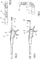
- Fig. 1 shows a perspective view of an instrument 10, the distal end facing the viewer and the proximal end facing away from the viewer.
- the instrument 10 is designed as an instrument for neurosurgery and / or brain surgery. Accordingly, the instrument 10 can also be referred to as a neurosurgical instrument.
- the instrument 10 has a shaft 12 which is formed at least in sections by a tube 14 which is rigid.
- the tube 14 defines a longitudinal axis of the shaft 12 that extends from a proximal end to a distal end.
- a joint section 16 is assigned to the shaft 12, which in FIG Fig. 1 is shown as an example in a deflected and / or angled position.
- an effector 20, which is designed approximately as a gripper, is received at the distal end of the shaft 12.
- the effector 20 comprises a first jaw part 22 and a second jaw part 24. In Fig. 1 the effector 20 is shown in an open position in which the jaw parts 22, 24 are open.
- a handling section 30 adjoins the proximal end of the shaft 12, in which the instrument 10 can be received and guided by a user, for example a surgeon or surgeon.
- the shaft 12 defines a distal portion of the instrument.
- the handling section 30 defines a proximal section of the instrument 10.
- the instrument 10 further comprises a deflection mechanism 32 for controlling the deflection and / or angular position of the joint section 16.
- the deflection mechanism 32 is provided with a control lever 34 as an example.
- the instrument 10 has an actuation mechanism 40 for the effector 20.
- the actuation mechanism 40 comprises a handle 42, which has a first arm 44 and a second arm 46. The arms 44, 46 extend from a proximal end of the handling section 30 distally in the direction of the shaft 12.
- the instrument 10 has an interface 48, to which a locking bracket 50 is assigned.
- the instrument 10 can be disassembled into a shaft assembly 52 and a handle 54.
- the shaft assembly 52 is a distal assembly.
- the handle 54 denotes a proximal assembly.
- the shaft assembly 52 is assigned to the shaft 12 at least in sections.
- the handle section 54 is assigned the handling section 30 at least in sections.
- at least the deflection mechanism 32 in particular the control lever 34, is assigned to the shaft assembly 52, that is to say arranged on the distal side of the interface 48.
- Other designs and Associations relate to the deflection mechanism 32 and / or the actuation mechanism 40 are conceivable.
- the locking bracket 50 is designed to lock the shaft assembly 52 and the handle 54 together.
- the locking bracket 50 is pivotable in order to allow the shaft assembly 52 to be released from the handle 54.
- Fig. 1 , 2 and 4 show that the handle 42 of the actuating mechanism 40 is received at a distal end of the handle 54, the arms 44, 46 being deflectable.
- the arms 44, 46 extend at least in sections laterally from the locking bracket 50 and from the control lever 34 of the deflection mechanism 32.
- the locking bracket 50 and the control lever 34 are arranged at least in sections between the arms 44, 46 of the handle 42.
- Fig. 1 configuration shown good manageability.
- the instrument 10 also has a favorable center of gravity, which simplifies holding and guiding the instrument 10.
- FIGS. 2 and 4 show broken side views of the in Fig. 1 Instrument 10 shown in perspective.
- Fig. 2 shows a first swivel state.
- Fig. 4 shows a second pivot state.
- Fig. 3 shows an enlarged view of a distal region of the shaft 12 of the instrument 10, wherein the pivoting state of the joint section 16 corresponds to that in FIG Fig. 2 shown state corresponds.
- Fig. 5 shows an enlarged view of the distal end of the shaft, wherein the in Fig. 5 shown state of the hinge portion 16 the in Fig. 4 corresponds to the swivel state shown.
- Fig. 2 shows a state in which the hinge section 16 is centered and is oriented concentrically to the longitudinal axis of the shaft 12.
- Fig. 5 shows a state in which the joint section 16 is deflected or angled to the maximum.
- the in 2 and 3 shown first swivel state is based on the Figures 6, 7 and 8 illustrated in more detail.
- the one in the Figures 4 and 5 shown second state of curvature is based on the Figures 9, 10 and 11 illustrated in more detail.
- Fig. 6 and Fig. 9 illustrate a pivotability of the control lever 34.
- Fig. 7 and Fig. 10 show corresponding sectional views.
- Fig. 8 shows a section through the joint portion 16 in the first state of curvature.
- Fig. 11 shows a section through the joint section 16 in the second state of curvature.
- the deflection mechanism 32 further comprises a control unit 58 to which the control lever 34 is assigned.
- the control lever 34 is pivotally received on a bearing piece 60.
- a pivot axis 62 for the control lever 34 is in Fig. 6 and Fig. 9 designated with 62.
- the control lever 34 is pivoted about the pivot axis 62.
- the control lever 34 is provided with adjusting screws 66, 68, which enable fine adjustment and / or adjustment of the angular positions of the control lever 34 in relation to the bearing piece 60.
- Fig. 7 shows the control unit 58 in a state in which the joint section 16 is in the first state of curvature, cf. also Fig. 8 . In this state, the adjusting screw 66 can contact the bearing piece 60 and provide an adjustable stop for the control lever 34 there.
- Fig. 10 illustrates a second state of the control lever 34 which corresponds to that in FIG Fig. 11 corresponds to the second state of curvature of the joint section 16 shown.
- the adjusting screw 68 contacts the bearing piece 60.
- an adjustable stop is also in the second state available, via which a fine adjustment and / or adjustment of the pivoting state of the control lever 34 can be carried out with respect to the bearing piece 60.
- FIGS. 7 and 10th further show that the control lever 34 and the bearing piece 60 are coupled to one another via sliding pieces 72, 74.
- a first slide 72 is assigned to a first tension element 76.
- a second slide 74 is assigned to a second tension element 78, cf. also Fig. 8 and Fig. 11 .
- the slider 72 is connected to the traction element 76 at a proximal end of the traction element 76 in order to take it along.
- the slider 74 is connected to the traction element 78 at a proximal end of the traction element 78 for movement.
- the pull element 76 is designed as a pull wire 80, for example.
- the pull element 78 is designed as a pull wire 82, for example.
- the tension elements 76, 78 are preferably made of a highly elastic material. This can be, for example, nitinol and / or a similar super-elastic alloy.
- the curved representation in Fig. 11 shows that the first tension element 76 can also be referred to as an inner tension element.
- the tension element 78 can also be referred to as an outer tension element, based on the respective radius of curvature of the tension elements 76, 78.
- the tension wire 80 can also be referred to as an inner tension wire.
- the pull wire 82 can also be referred to as an outer pull wire.
- the joint section 16 can be deflected and / or angled by pulling the pull element 76 distally, cf. Fig. 11 . By pulling on the pulling element 78, the joint section 16 can be folded in or retracted in order to assume its starting position, which corresponds approximately to a central position, cf. also Fig. 8 .
- pivoting the control lever 34 in the direction of the distal end of the instrument 10 causes the articulated section 16 to be deflected into an angled position.
- Turned upside down produces a pivoting movement of the control lever 34 in the direction of the proximal end of the instrument 10, a pull on the pulling element 78.
- the articulated section 16 is moved from the curved back into the straight, central position.
- the joint section 16 is based on the Fig. 8 and the Fig. 11 illustrated in more detail.
- the joint section 16 includes, for example, a joint member 88 and a joint member 90, which are received between a proximal connecting piece 92 and a distal connecting piece 94.
- Pivot axes 96, 98, 100 illustrate that the arrangement comprising the connecting piece 92, the articulated member 88, the articulated member 90 and the connecting piece 94 can be pivoted as a whole, each comprising a relative pivoting of adjacent links.
- the articulated members 88, 90 and preferably also the connecting pieces 92, 94 are preferably provided with stops 106, 108, 110, 112.
- Stop 106, 108 lying opposite one another are shown by way of example, the stop 106 being assigned to the joint member 88 and the stop 108 being assigned to the joint member 90. It goes without saying that there are further stops on this page.
- Fig. 11 shows that in the curved state of the joint section 16, the stops 106, 108 contact each other.
- Fig. 11 shows Fig. 11 that further stops 110, 112 are provided, which define a straight, stretched orientation of the joint section 16.
- the stop 110 is assigned to the joint member 88.
- the stop 112 is assigned to the joint member 90.
- Other members involved are similarly provided with stops.
- a comparison between Fig. 8 and Fig. 11 shows that the stops 110, 112 are used to define the straight, central orientation of the joint section 16. At least the central position of the joint section 16 is defined in a highly precise and repeatable manner by the stops 110, 112.
- the stops 106, 108 can be designed to ensure high positioning accuracy and repeatability even for the angled / deflected state of the joint section 16.
- Fig. 8 and Fig. 11 The embodiment shown also shows that the tension elements 76, 78 are used to pivot and / or return the joint section 16. However, the actual positioning in the respective end positions is carried out by the stops 106, 108 for the in Fig. 11 position shown and the stops 110, 112 for the in Fig. 8 position shown.
- 12 and 13 each show exploded perspective views, the views being based on different orientations.
- control lever 34 is made in two parts and is provided with a first side part 118 and a second side part 120.
- the side parts 118, 120 can be screwed together, for example.
- the first side part 118 is provided with a bearing recess 122.
- the second side part 120 is provided with a bearing recess 124.
- a bearing pin 126 is provided which can be received in a bearing recess 128 on the bearing piece 60.
- the side part 118 is received on the bearing pin 126 via the bearing recess 122.
- the side part 120 is received on the bearing bolt 126 via the bearing recess 124. Accordingly, the control lever 34, which includes the side parts 118, 120, can be pivoted about the bearing pin 126.
- bearing pin 126 can also be formed integrally on the bearing piece 60. According to this exemplary embodiment, no separate bearing recess 128 is provided on the bearing piece 60.
- FIGS. 12 and 13 are also indicated with 130, 132 elastic clamping bodies, which are provided for increasing friction or securing the position.
- the clamping bodies 130, 132 can, for example, be designed as so-called O-rings.
- the Figures 12 and 13 show that each side end of the bearing pin 126 has two clamping bodies 130, 132 are assigned.
- the one or more clamping bodies 130 is / are provided between the bearing pin 126 and the bearing recess 122.
- the one or more clamping bodies 132 is / are provided between the bearing pin 126 and the bearing recess 124.
- the side parts 118, 120 of the control lever 34 also have mounting openings 134, 136.
- the mounting opening 134 provided on the side part 118 includes, for example, a thread.
- the mounting opening 136 provided on the side part 120 includes, for example, a through hole for a screw.
- control lever 34 In the assembled state, the control lever 34 can be pivoted about the bearing pin 126, the clamping bodies 130, 132 causing an increase in friction, which can result in self-locking or position securing. In other words, it is preferred if the control lever 34 maintains its actual pivot position relative to the bearing piece 60 automatically and without external influence.
- the corresponding frictional forces are primarily generated by the clamping bodies 130, 132, which are received with a prestress between the bearing piece 60 and the side part 118 and between the bearing piece 60 and the side part 120.
- FIG. 12 shows a sectional view of the control unit 58 for the deflection mechanism 32.
- Fig. 15 shows an isolated side view of a control lever 34.
- a first guideway 138 and a second guideway 140 are formed on the control lever 34. Also show in particular 12 and 13 that a first guideway 144 and a second guideway 146 are formed on the bearing piece 60.
- the slider 72 for the first tension element 76 is received in the assembled state in the guideway 144 of the bearing piece 60 and the guideway 138 of the control lever 34.
- the slider 74, which is assigned to the tension element 78, is received in the guideway 146 of the bearing piece 60 and the guideway 140 of the control lever 34.
- the slides 72, 74 are driven via the guide tracks 138, 140, cf. also Fig. 15 .
- the sliders 72, 74 are coupled to the tension elements 76, 78. In this way, the joint section 16 can be stretched or angled at the distal end of the instrument.
- Fig. 15 shows that the guideways 138, 140 are received on the control lever 34 in a certain way relative to the bearing recess 122, 124. This has the effect that when the control lever 34 is pivoted about the pivot axis 62, the tension elements 76, 78 are not displaced by the same amount. This measure has the advantage that different bending radii of the tension elements 76, 78 can be compensated, cf. also about this Fig. 11 .
- control unit 58 is designed in such a way that both tension elements 76, 78 are at least slightly pretensioned in their longitudinal direction. This has the advantage that the deflection mechanism 32 is designed with little or almost no play. Excessive play can thus be avoided, in particular when the movement is reversed.
- a passage 150 extends between a distal and a proximal end.
- the passage 150 is, for example, concentric to a longitudinal axis through the shaft 12.
- Fig. 14 shows a state of the instrument 10, in which the shaft 12 and the bearing piece 60 are joined together, wherein in the shaft 12 a Thrust piece 154 is arranged, which extends through the passage 156 in the bearing pin 126.
- Fig. 12, Fig. 13 and Fig. 14 further show that in addition to the tension elements 76, 78, the thrust piece 154 is also received on the shaft 12, in particular in the tube 14.
- a passage 156 for the thrust piece 154 is provided on the bearing pin 126 so that it can be passed centrally through the bearing pin 126.
- a pressure piece 160 is provided, which is connected to the push piece 154.
- Fig. 14 is also indicated by 158 a compression spring or spring which is received between the pressure piece 160 and a stop 162 on the bearing piece 60 in order to urge the thrust piece 154 in the direction of the proximal end. This can also contribute to the design of the control unit 58 and the deflection mechanism 32 with little or no play.
- FIG. 16 17 and 18 show an effector 20 received at the distal end of the shaft, which is designed as a gripper 164 as an example. It is understood that the effector 20 can alternatively also be designed as pliers, pinchers, scissors, clamps and in a similar manner.
- FIG. 19 corresponds with Fig. 16 .
- Fig. 20 corresponds with Fig. 17 .
- Fig. 21 corresponds with Fig. 18 .
- a head piece 166 is accommodated, which is designed, for example, as a fork head 168.
- the head piece 166 comprises a first side part 170 and a second side part 172.
- a coupling piece 174 is slidably received between the side parts 170, 172, the coupling piece 174 comprising a flat piece 176 at its distal end.
- a driver 178 extends from the flat piece 176 and a further driver 180. The drivers 178, 180 are received on sides of the flat piece 176 facing away from one another.
- the coupling piece 174 is coupled to the first jaw part 22 and the second jaw part 24 via the drivers 178, 180.
- a driving recess 186 is provided on the first jaw part 22.
- a second driving recess 188 is provided on the second jaw part 24.
- the driver 178 engages in the driver recess 186 on the jaw part 22.
- the driver 180 engages in the driver recess 188 on the second jaw part 24.
- first jaw part 22 has a projection 194.
- second jaw part 24 has a projection 196.
- a bearing recess 198 on the head piece 166 is assigned to the first projection 194.
- a bearing recess 200 on the head piece 166 is assigned to the second projection 196.
- the projection 194 extends from a flat piece 202 of the first jaw part 22.
- the projection 196 extends from a flat piece 204 of the second jaw part 24.
- a guide track 206 is formed in the flat piece 202.
- a guide track 208 is formed in the flat piece 204.
- a guide pin 214 is also provided which extends through a guide recess 216 in the flat piece 176 of the head piece 166.
- the guide pin 214 is received on a seat 222 on the side part 170 and a seat 224 on the side part 172.
- the coupling piece 174 and the first jaw part 22 and the second jaw part 24 are received between the side parts 170, 172, in particular via their flat pieces 176, 202, 204.
- the flat piece 176 of the coupling piece 174 is between the flat pieces 202, 204 of the jaw parts 22, 24 added.
- the guide pin 214 extending between the seats 222, 224 also extends through the guide track 206 on the first jaw part 22, the guide track 208 on the jaw part 24 and the guide recess 216 in the flat piece 176 of the coupling piece 174.
- a comparison of 16, 17 and 18 With 19, 20 and 21 shows that the coupling piece 174 is pushed distally to close the jaw parts 22, 24. If the coupling piece 174 is pushed or pushed proximally, the jaw parts 22, 24 open.
- the push piece 154 described is connected to the coupling piece 174 in order to move the latter to close or open the effector 20.
- the push piece 154 can also consist of a highly elastic material or even a super-elastic alloy, such as nitinol.
- the actuating mechanism 40 for the effector 20 is illustrated in more detail.
- the handle 42 of the actuating mechanism 40 is received at the distal end of the instrument 10.
- the handle 42 is received on a support shaft 228 which is connected to the bearing piece 60 and to the shaft 12 in series.
- the bearing piece 60 and the support shaft 228 are hidden for the sake of illustration.
- the arms 44, 46 of the handle 42 in the Figures 22 and 23 not explicitly shown (cf. Fig. 1 ).
- the arms 44, 46 are designed as attachment parts.
- the actuating mechanism 40 comprises a coupling mechanism 230 which has a slide 232 which can be coupled to the pressure piece 160 which is provided at the proximal end of the thrust piece 154.
- the slider 232 comprises a quiver-like seat 234 and an adjoining flat piece 236.
- the slider 232 can be plugged onto the pressure piece 160 in order to press it towards the distal end of the instrument.
- a counter-force is generated by the spring 158 which in Fig. 23 is indicated.
- the installation state of the spring can be roughly as shown in Fig. 14 be removed, cf. also about this Fig. 26 .
- the handle 42 comprises actuation sections 238, 240 which extend approximately like pliers from proximal to distal. Between the operating sections 238, 240 extends the support shaft 228, at the distal end of which the handle 42 is attached.
- the actuating section 238 is coupled via a coupling member 246 to the flat piece 236 of the quiver-like slide 232.
- the actuating section 240 is connected to the flat piece 236 via a coupling member 248.
- the coupling links 246, 248 have the same pivot point on the flat piece 236 of the slide 232.
- the coupling member 246 is articulated on the actuating section 238 via a bearing pin 254.
- the coupling member 248 is articulated on the actuating section 240 via a bearing pin 256.
- the coupling links 246, 248 extend through passages 250 which are formed in the support shaft 228, cf. also the representation of the support shaft 228 with the passage 250 in Fig. 25 .
- a hinge section 262 is formed on the actuating section 238.
- a hinge section 264 is formed on the actuating section 240, cf. Fig. 22 .
- the articulated sections 262, 264 can, for example, have a material weakening in order to provide a materially integral swivel joint and / or a virtual pivot point or a virtual swivel axis for the actuating sections 238, 240.
- the actuating mechanism 40 for the effector 20 is also designed with little or no play.
- the pressure piece 160 is formed at the proximal end of the thrust piece 154 and is pushed by the spring 158 in the direction of the proximal end of the instrument. From the distal end, the coupling mechanism 230 acts on the pressure piece 160 via the slide 232 and urges it against the force of the spring 158 in the direction of the proximal end of the instrument 10 when the actuating sections 238, 240 are moved towards one another. If also the coupling mechanism 230 acts at least with a slight preload on the pressure piece 160, this can be accommodated with little or no play "floating" between the coupling mechanism 230 and the spring 158.
- the coupling mechanism 230 can be designed in such a way that the actuating sections 238, 240 push inward even in an unloaded state and thus a pretensioning force is generated on the slide 232.
- the interface 48 can be locked or unlocked via a locking bracket 50.
- the interface comprises a male fitting part 270 and a female fitting part 272.
- the male fitting part 270 can also be referred to as an inner part.
- the female fitting part 272 can also be referred to as an outer part.
- Male fitting 270 is insertable into female fitting 272 to align shaft assembly 52 and handle 54.
- a holding section 276 is formed on the female fitting part 272, for example in the form of a step or a shoulder.
- the closing bracket 50 has a holding bracket 278 at its distal end, cf. especially the representation in Fig. 25 , which shows the locking bracket 50 in isolated form.
- the locking bracket 50 can engage the holding section 276 via the holding bracket 278 in order to lock the joined state of the male fitting part 270 with the female fitting part 272.
- the holding bracket 278 includes, for example, a position securing section 280, which is followed by a release section 282, cf. in turn Fig. 25 .
- the position securing section 280 comprises a constriction.
- the release section 282 includes an expansion. Together, the position securing section 280 and the release section 282 can form a keyhole contour.
- the locking bracket 50 is over a Joint 288 pivotally received on a bearing piece 286.
- the bearing piece 286 is arranged on the support shaft 228.
- the position securing section 280 or the release section 282 is aligned with the holding section 276.
- the locking bracket 50 is pivoted in such a way that the release section 282 is aligned essentially concentrically with the support shaft 228 or with the male fitting part 270. Then the male fitting part 270 can be joined with the female fitting part 272, cf. also the state in Fig. 26 .
- the locking bracket 50 can be pivoted such that the position securing section 280 engages the holding section 276 in order to secure the joining state between the male fitting part 270 and the female fitting part 272.
- an opposite movement can be applied to the closing bracket 50 in order to lead the position securing section 280 out of the locked state on the holding section 276. It is conceivable to accommodate the locking bracket 50 on the carrier shaft 228 in such a way that there is a pretension in the direction of the locked state. This can further increase security. The risk of incorrect operation can be reduced.
- the position securing section 280 on the holding bracket 278 of the locking bracket 50 is designed such that disengagement from the holding section 276 is only possible by elastic deformation, for example by lateral expansion, of the locking bracket 50 in the area of the holding bracket 278. In this way, a certain force must be applied in order to disengage the position securing section 280 and to align the release section 282, which has a larger cross section, with the holding section 276. Furthermore, it is conceivable to form a recess 290 on a back of the locking bracket 50, which opens into the position securing section 280. In this way, a defined deformability of the holding arm 278 is provided in the area of the position securing section 280.
- a groove 292 is formed on the female fitting part 272, for example.
- the groove 292 extends axially and is open at its proximal end.
- a guide pin 294 is arranged on the male fitting part 270 and is oriented radially to a longitudinal axis of the instrument 10. When the male fitting part 270 is joined to the female fitting part 272, the guide pin 294 can engage in the groove 292 in order to secure the desired rotational position.
- the cut representations in 26 and 27 illustrate that a conical surface 300 is formed on the male fitting part 270, which is adjoined by a cylindrical surface 304.
- a conical surface 302 is formed on the female fitting part 272, which is adjoined by a cylindrical surface 306.
- the cone surface 302 and the cylinder surface 306 are inner surfaces.
- the cone surface 300 and the cylinder surface 304 are outer surfaces.
- fitting parts 270, 272 can be primarily provided with the cylinder surfaces 304, 306, which ensure a concentric design.
- the interface 48 also includes the pressure piece 160 on the shaft assembly 52 side and the slider 232 on the handle 54 side.
- a sliding movement can be transmitted to the pressure piece 160 via the slide 232 in order to displace the push piece 154 in the direction of the distal end of the instrument in order to control the effector 20.
- Pressure forces are primarily transmitted to the pressure piece 160 via the slider 232.
- a connection can be produced in a simple manner by pushing the slider 232 onto the pressure piece 160.
- a restoring movement or restoring force is generated by the spring 158, which is located between the pressure piece 160 and the bearing piece 60 is arranged, wherein the spring 158 is aligned concentrically to the longitudinal axis of the instrument 10.
- the movement transmission for the degree of freedom of movement of the effector 20 is designed with little or no play.
Description
Die vorliegende Offenbarung betrifft ein chirurgisches Instrument, insbesondere ein Instrument, das für die Neurochirurgie nutzbar ist. Ein solches Instrument kann auch als neurochirurgisches Instrument bezeichnet werden. Ein weiteres Anwendungsgebiet für derartige Instrumente ist das Gebiet der Hirnchirurgie. Die Begriffe "Hirnchirurgie" und "Neurochirurgie" haben einen sich zumindest teilweise überlappenden Bedeutungsgehalt.The present disclosure relates to a surgical instrument, in particular an instrument that can be used for neurosurgery. Such an instrument can also be referred to as a neurosurgical instrument. Another area of application for such instruments is the field of brain surgery. The terms "brain surgery" and "neurosurgery" have an at least partially overlapping meaning.
Chirurgische Instrumente im Sinne der vorliegenden Offenbarung umfassen einen Schaft, einen proximalen Handhabungsabschnitt an einem proximalen Ende des Schaftes, und einen distalen Effektor an einem distalen Ende des Schaftes, wobei der Effektor über einen Betätigungsmechanismus gesteuert wird. Bei dem Effektor kann es sich etwa um eine Zange, Schere, Schneide, Klemme, Koagulationsklemme und dergleichen handeln. Ferner ist die Gestaltung des Effektors als Kürette, Biopsiezange oder in ähnlicher Weise vorstellbar.Surgical instruments in the sense of the present disclosure include a shaft, a proximal handling section at a proximal end of the shaft, and a distal effector at a distal end of the shaft, the effector being controlled via an actuation mechanism. The effector can be a pair of pliers, scissors, cutting edge, clamp, coagulation clamp and the like. Furthermore, the design of the effector is conceivable as a curette, biopsy forceps or in a similar manner.
Allgemein betrifft die vorliegende Offenbarung Instrumente auf dem Gebiet der minimal-invasiven Chirurgie. In diesem Zusammenhang ist anzumerken, dass im Bereich der Neurochirurgie und/oder der Hirnchirurgie sehr hohe Anforderungen an die Kompaktheit des Instruments, die Führungsgenauigkeit, die Bedienbarkeit sowie die Präzision allgemein bestehen. Die vorstehend beschriebenen Anforderungen gelten grundsätzlich auch für chirurgische Instrumente allgemeiner Art, wie etwa endoskopische und/oder laparoskopische Instrumente. Jedoch gelten für neurochirurgische Instrument und/oder gehirnchirurgische Instrumente noch andere Maßstäbe und Anforderungen. Es hat sich gezeigt, dass Konstruktionsprinzipien, die bei chirurgischen Instrumenten und invasiven Instrumenten allgemeiner Art umsetzbar sind, nicht direkt auf neurochirurgische und/oder hirnchirurgische Instrumente übertragbar sind.In general, the present disclosure relates to instruments in the field of minimally invasive surgery. In this context, it should be noted that in the field of neurosurgery and / or brain surgery there are very high requirements for the compactness of the instrument, the guidance accuracy, the usability and the precision in general. The requirements described above also apply in principle to general-purpose surgical instruments, such as endoscopic and / or laparoscopic instruments. However, other standards and requirements apply to neurosurgical instruments and / or brain surgical instruments. It It has been shown that construction principles that can be implemented in general for surgical instruments and invasive instruments cannot be directly applied to neurosurgical and / or brain-surgical instruments.
Dies schließt nicht aus, dass Instrumente im Sinne der vorliegenden Offenbarung für die HNO-Chirurgie (Hals-Nasen-Ohren Chirurgie) und andere klassische Bereiche der Chirurgie nutzbar sind. Allgemein können derartige Instrumente dann genutzt werden, wenn ein geringer Platzbedarf und eine gewisse Flexibilität gefordert ist. Instrumente gemäß der vorliegenden Offenbarung können als Miniatur-Instrumente gestaltet sein, insbesondere im Hinblick auf ihren Schaftdurchmesser.This does not exclude that instruments within the meaning of the present disclosure can be used for ENT surgery (ear, nose and throat surgery) and other classic areas of surgery. In general, such instruments can be used if a small space requirement and a certain flexibility is required. Instruments according to the present disclosure can be designed as miniature instruments, particularly with regard to their shaft diameter.
Im Sinne der vorliegenden Offenbarung ist eine proximale Seite eine vom Patienten abgewandte und einem Operateur zugewandte Seite des Instruments. Demgemäß ist eine distale Seite eine dem Patienten zugewandte und vom Operateur abgewandte Seite des Instruments. Insbesondere auf dem Gebiet der invasiven Chirurgie wird das distale Ende des Instruments in das Körperinnere des Patienten eingeführt. Üblicherweise wird das Instrument am proximalen Ende gehalten bzw. geführt, wobei auch Ausführungsformen vorstellbar sind, bei denen sich das proximale Ende des Instruments über den Handhabungsabschnitt hinaus erstreckt.In the sense of the present disclosure, a proximal side is a side of the instrument facing away from the patient and facing an operator. Accordingly, a distal side is a side of the instrument facing the patient and facing away from the surgeon. Particularly in the field of invasive surgery, the distal end of the instrument is inserted into the patient's body. The instrument is usually held or guided at the proximal end, and embodiments are also conceivable in which the proximal end of the instrument extends beyond the handling section.
Aus der
Aus der
Aus der
Aus der
Aus der
Aus der
Aus der
Aus der
Aus der
Eine neurochirurgische oder hirnchirurgische Behandlung umfasst bspw. das Setzen eines Zugangs an der Schädeldecke eines Patienten. Beispielhaft wird eine Bohrung in die Schädeldecke eingebracht, durch die ein Instrument in den Schädel einführbar ist. Bekannte neurochirurgische Instrumente, vergleiche die obige
Die Zugänge in das Körperinnere des Patienten, insbesondere in den Kopf und/oder den Wirbelsäulenbereich, können nicht beliebig groß ausgeführt werden. Das Ziel ist es, Traumata für den Patienten möglichst zu minimieren. Diese Konstellation kann jedoch dazu führen, dass das Instrument einen gewünschten Zielort im Körperinneren, etwa im Kopf des Patienten, schlichtweg nicht erreichen kann, da der Schaft als Ganzes nicht beliebig verschwenkbar ist. Dies würde unter Umständen dazu führen, dass ein weiterer Zugang hergestellt werden muss.The entrances into the interior of the patient's body, in particular into the head and / or the spinal area, cannot be of any size. The goal is to minimize trauma for the patient as much as possible. However, this constellation can mean that the instrument simply cannot reach a desired destination inside the body, for example in the patient's head, since the shaft as a whole cannot be pivoted at will. Under certain circumstances, this would lead to further access having to be established.
In anderen Bereichen der Chirurgie, etwa auf dem Gebiet der laparoskopischen Chirurgie, sind abwinkelbare Instrumente bekannt. Solche Instrumente weisen Schwenkmechanismen und/oder Auslenkmechanismen auf, die etwa am Schaft selbst oder am distalen Ende des Schaftes ausgebildet sind. Auf diese Weise kann ein zusätzlicher Bewegungsfreiheitsgrad für das Instrument bereitgestellt werden. Beispielhaft kann eine am distalen Ende des Instruments aufgenommene Zange insgesamt verschwenkt werden.In other areas of surgery, for example in the field of laparoscopic surgery, angled instruments are known. Such instruments have swivel mechanisms and / or deflection mechanisms which are formed, for example, on the shaft itself or on the distal end of the shaft. In this way, an additional degree of freedom of movement can be provided for the instrument. For example, a pair of forceps picked up at the distal end of the instrument can be pivoted as a whole.
Auf diese Weise können etwa Bereiche im Körperinneren erreicht werden, die seitlich von einer gedachten Hauptachse des Schaftes beabstandet sind. Wie vorstehend bereits ausgeführt, weisen jedoch konventionelle endoskopische Instrumente und/oder laparoskopische Instrumente grundsätzlich größere Abmessungen auf, als neurochirurgische Instrumente. Beispielsweise kann ein Schaftdurchmesser eines laparoskopischen Instruments 10 mm, 12 mm, oder sogar noch mehr betragen. Der Schaftdurchmesser eines neurochirurgischen Instruments, das etwa auf dem Gebiet der Hirnchirurgie genutzt wird, ist deutlich kleiner. Hier kann ein Schaftdurchmesser etwa maximal 3,5 mm, vorzugsweise maximal 3,0, mm, weiter bevorzugt etwa 2,7 mm oder gar weniger betragen. Schon aus diesem Grund können grundsätzlich bekannte Konstruktionsprinzipien für auslenkbare und/oder abwinkelbare Instrumente nicht ohne weiteres auf das Gebiet der Neurochirurgie übertragen werden.In this way, areas inside the body can be reached that are laterally spaced from an imaginary main axis of the shaft. As already stated above, however, conventional endoscopic instruments and / or laparoscopic instruments generally have larger dimensions than neurosurgical instruments. For example, a shaft diameter of a laparoscopic instrument can be 10 mm, 12 mm, or even more. The shaft diameter of a neurosurgical instrument, which is used in the field of brain surgery, for example, is significantly smaller. Here, a shaft diameter can be a maximum of about 3.5 mm, preferably a maximum of 3.0 mm, more preferably about 2.7 mm or even less. For this reason alone, well-known design principles for deflectable and / or angled instruments cannot easily be applied to the field of neurosurgery.
Eine weitere Anforderung, die für neurochirurgische und/oder hirnchirurgische Instrumente im Besonderen gilt, ist die Genauigkeit der Bewegung und/oder die Positionierbarkeit, Positioniergenauigkeit, sowie die Positionierwiederholbarkeit.Another requirement, which applies in particular to neurosurgical and / or brain-surgical instruments, is the accuracy of the movement and / or the positionability, positioning accuracy, and the position repeatability.
Insbesondere bei Operationen, die im Gehirn des Patienten vorgenommen werden, können kleinste Abweichungen und Ungenauigkeiten zu Beschädigungen des benachbarten Gewebes führen. Auch hier gilt, dass sich Gestaltungsprinzipien bekannter abwinkelbarer Instrumente aus dem Bereich der laparoskopischen Chirurgie nicht ohne weiteres auf den Bereich der Neurochirurgie übertragen lassen.Especially in operations that are performed in the patient's brain, the smallest deviations and inaccuracies can lead to damage to the neighboring tissue. It also applies here that design principles of known angled instruments from the field of laparoscopic surgery cannot be easily applied to the field of neurosurgery.
Effektive Wege und Bewegungen, die das Instrument bspw. im Schädel des Patienten ausführt, sind sehr klein. Dies bedingt eine ausgeprägte Feinfühligkeit und Führungsgenauigkeit der Instrumente und der daran/darin verbauten Mechanismen. Bei neurochirurgischen Instrumenten hat die Ergonomie und Handhabbarkeit eine sehr hohe Bedeutung. Das Instrument soll feinfühlig und hochgenau positioniert werden können. Die Positionierung soll mit hoher Wiederholgenauigkeit erfolgen.Effective paths and movements that the instrument executes in the patient's skull, for example, are very small. This requires a pronounced sensitivity and guiding accuracy of the instruments and the mechanisms built into them. Ergonomics and manageability are very important for neurosurgical instruments. The instrument should be able to be positioned sensitively and with high precision. The positioning should be done with high repeatability.
Grundsätzlich ist es vorstellbar, neurochirurgische Instrumente mit nicht auslenkbaren/abwinkelbaren Schäften zu nutzen. Jedoch weisen derartige Instrumente nur einen sehr begrenzten Aktionsradius auf. Es gibt Extremfälle, bei denen Instrumente mit geraden Schäften das Arbeitsgebiet schlichtweg nicht erreichen können, da kein geeigneter Zugang (etwa Bohrung in die Schädeldecke) platziert werden kann.Basically, it is conceivable to use neurosurgical instruments with shafts that cannot be deflected / angled. However, such instruments only a very limited radius of action. There are extreme cases in which instruments with straight shafts simply cannot reach the working area because no suitable access (e.g. drilling into the skull cap) can be placed.
Ferner besteht der Wunsch nach zerlegbaren Instrumenten auch auf dem Gebiet der Neurochirurgie. Ein zerlegbares Instrument weist zumindest eine Schnittstelle auf, an der Baugruppen des Instruments definiert voneinander lösbar sind. Dies kann bspw. eine Schaftbaugruppe und ein Griffstück des Instruments betreffen. Es hat sich gezeigt, dass die Gestaltung zerlegbarer Instrumente häufig zu einer Verringerung der Genauigkeit führt. Mit anderen Worten ist zu beobachten, dass entsprechende Schnittstellen, die für die Zerlegbarkeit der Instrumente erforderlich sind, häufig einen Anstieg des mechanischen Spiels und folglich eine Verringerung der Führungsgenauigkeit bedingen.There is also a desire for disassemblable instruments in the field of neurosurgery. An instrument that can be dismantled has at least one interface at which modules of the instrument can be detached from one another in a defined manner. This can concern, for example, a shaft assembly and a handle of the instrument. It has been shown that the design of disassembled instruments often leads to a reduction in accuracy. In other words, it can be observed that corresponding interfaces, which are necessary for the dismantling of the instruments, often cause an increase in the mechanical play and consequently a reduction in the guiding accuracy.
Ferner besteht bei chirurgischen Instrumenten, die abwinkelbar/auslenkbar gestaltet sind, häufig eine Wechselwirkung zwischen den beteiligten Freiheitsgraden. Mit anderen Worten kann bspw. eine Betätigung eines Effektors (etwa Öffnen und Schließen einer Zange) gewisse Auswirkungen auf einen Mechanismus für die Auslenkung/Abwinkelfunktion des Instruments haben. Auch dies kann grundsätzlich zu einer Verringerung der Genauigkeit und zu einer Erhöhung des Spiels im System führen.Furthermore, there is often an interaction between the degrees of freedom involved in surgical instruments that are designed such that they can be angled / deflected. In other words, actuation of an effector (such as opening and closing a pair of pliers) can have certain effects on a mechanism for the deflection / bending function of the instrument. This can also lead to a reduction in accuracy and an increase in game play in the system.
Vor diesem Hintergrund liegt der vorliegenden Offenbarung die Aufgabe zugrunde, ein chirurgisches Instrument, insbesondere ein für die Neurochirurgie und/oder Hirnchirurgie geeignetes Instrument, anzugeben, das mit hoher Genauigkeit und Präzision bedienbar ist. Freiheitsgrade des Instruments sollen präzise und mit hoher Wiederholgenauigkeit steuerbar sein. Das Instrument ist möglichst mit nur einem geringen Spiel in den beteiligten Bewegungsmechanismen für die Freiheitsgrade versehen. Vorzugsweise ist das Instrument zerlegbar gestaltet, wobei sich ergebende Schnittstellen keine nachteiligen Auswirkungen auf die Genauigkeit bzw. das Spiel im System mit sich bringen. Es ist weiter bevorzugt, wenn das Instrument einen erweiterten Operationsradius bzw. ein erweitertes Operationsgebiet aufweist, so dass auch Gewebebereiche erreichbar sind, die bei gesetztem Instrument von einer Hauptachse des Schaftes beabstandet sind. Das Instrument soll eine spielarme oder gar spielfreie Ansteuerung sowohl des Effektors als auch einer Winkelposition/Auslenkposition des Effektors als Ganzes in Bezug auf den Schaft ermöglichen.Against this background, the present disclosure is based on the object of specifying a surgical instrument, in particular an instrument suitable for neurosurgery and / or brain surgery, which can be operated with high accuracy and precision. Degrees of freedom of the instrument should be controllable precisely and with high repeatability. As far as possible, the instrument is provided with only a slight play in the movement mechanisms involved for the degrees of freedom. The instrument is preferably designed such that it can be dismantled, the resulting interfaces having no adverse effects on the accuracy or the play in the system. It is further preferred if the instrument has an enlarged operating radius or an enlarged operating area so that tissue areas can also be reached which are spaced from a main axis of the shaft when the instrument is set. The The instrument is intended to enable low-play or even play-free control of both the effector and an angular position / deflection position of the effector as a whole in relation to the shaft.
Gemäß einem ersten Aspekt wird die Aufgabe der Erfindung durch ein chirurgisches Instrument, insbesondere ein Instrument für die Neurochirurgie, gelöst, wobei das Instrument Folgendes aufweist:
- einen Schaft, wobei am Schaft ein Gelenkabschnitt ausgebildet ist, insbesondere ein Gelenkabschnitt, der ausgehend von einer Mittelposition einseitig auslenkbar ist,
- einen proximalen Handhabungsabschnitt an einem proximalen Ende des Schaftes,
- einen distalen Effektor an einem distalen Ende des Schaftes, und
- einen Auslenkmechanismus zur Steuerung eines Krümmungszustands des Gelenkabschnitts, der ein erstes Zugelement, insbesondere für eine Auslenkbewegung, sowie ein zweites Zugelement, insbesondere für eine Rückkehrbewegung, aufweist,
wobei das erste Zugelement als erster Zugdraht und das zweite Zugelement als zweiter Zugdraht ausgebildet ist, die auf einander gegenüberliegenden Seiten eines Zentrums des Schaftes angeordnet sind,
wobei sich die Zugelemente jeweils zwischen einem proximalen Koppelpunkt und einem distalen Koppelpunkt im Schaft erstrecken, und wobei die Zugelemente an ihrem proximalen Ende mit einer Steuereinheit gekoppelt sind, die einen schwenkbaren Steuerhebel umfasst,
wobei die Steuereinheit eine Zwangssteuerung für das erste Zugelement und das zweite Zugelement bereitstellt, die die gemeinsame Vorspannung des ersten Zugelements und des zweiten Zugelements bewirkt,
wobei die Steuereinheit am Steuerhebel eine erste Führungsbahn für das erste Zugelement und eine zweite Führungsbahn für das zweite Zugelement aufweist,
wobei am Handhabungsabschnitt eine erste Führungsbahn für das erste Zugelement und eine zweite Führungsbahn für das zweite Zugelement vorgesehen ist,
wobei die erste Führungsbahn und die zweite Führungsbahn des Handhabungsabschnitts an einem Lagerstück ausgebildet sind,
dass der Steuerhebel ein erstes Seitenteil und ein zweites Seitenteil aufweist, die über einen Lagerbolzen um das Lagerstück verschwenkbar sind,
wobei die erste Führungsbahn und die zweite Führungsbahn sowohl im ersten Seitenteil als auch im zweiten Seitenteil des Steuerhebels ausgebildet sind, und wobei für das erste Zugelement ein erstes stiftförmiges Gleitstück vorgesehen ist, das in der ersten Führungsbahn des Lagerstücks und der ersten Führungsbahn des Steuerhebels aufgenommen ist, und wobei für das zweite Zugelement ein zweites stiftförmiges Gleitstück vorgesehen ist, das in der zweiten Führungsbahn des Lagerstücks und der zweiten Führungsbahn des Steuerhebels aufgenommen ist.According to a first aspect, the object of the invention is achieved by a surgical instrument, in particular an instrument for neurosurgery, the instrument having the following:
- a shaft, a joint section being formed on the shaft, in particular a joint section which can be deflected on one side starting from a central position,
- a proximal handling section at a proximal end of the shaft,
- a distal effector at a distal end of the shaft, and
- a deflection mechanism for controlling a state of curvature of the joint section, which has a first tension element, in particular for a deflection movement, and a second tension element, in particular for a return movement,
wherein the first tension element is designed as a first tension wire and the second tension element as a second tension wire, which are arranged on opposite sides of a center of the shaft,
wherein the traction elements each extend between a proximal coupling point and a distal coupling point in the shaft, and wherein the traction elements are coupled at their proximal end to a control unit which comprises a pivotable control lever,
wherein the control unit provides a positive control for the first tension element and the second tension element, which brings about the common pretensioning of the first tension element and the second tension element,
wherein the control unit on the control lever has a first guideway for the first tension element and a second guideway for the second tension element,
a first guideway for the first traction element and a second guideway for the second traction element being provided on the handling section,
wherein the first guideway and the second guideway of the handling section are formed on a bearing piece,
that the control lever has a first side part and a second side part which can be pivoted about the bearing piece via a bearing pin,
wherein the first guideway and the second guideway are formed both in the first side part and in the second side part of the control lever, and wherein a first pin-shaped slider is provided for the first tension element, which is received in the first guideway of the bearing piece and the first guideway of the control lever , and wherein a second pin-shaped slider is provided for the second tension element, which is received in the second guideway of the bearing piece and the second guideway of the control lever.
Die Aufgabe der Erfindung wird auf diese Weise vollkommen gelöst.The object of the invention is completely achieved in this way.
Erfindungsgemäß erlaubt nämlich die Gestaltung der Zugelemente eine spielarme oder sogar spielfreie Auslenkbewegung bzw. Ablenkung des Gelenkabschnitts. Dies wird dadurch erreicht, dass beide Zugelemente, von denen eigentlich beim Ausschwenken bzw. Einschwenken jeweils nur eines unter Spannung (Zugspannung) gesetzt wird, gemeinsam und richtungsgleich unter Spannung gesetzt werden. Dies bedeutet bspw., dass die Auslenkbewegung weiterhin über einen Zug am ersten Zugelement erfolgt.According to the invention, the design of the tension elements allows a low-play or even play-free deflection or deflection of the joint section. This is achieved in that both tension elements, of which only one is put under tension (tension tension) when swiveling out or in, are put under tension together and in the same direction. This means, for example, that the deflection movement continues via a pull on the first pull element.
Jedoch wird das zweite Zugelement während der Auslenkbewegung zumindest abschnittsweise auch vorgespannt, wenn auch nur mit deutlich geringerer Spannung als das erste Zugelement. Bei der Rückkehrbewegung ist es umgekehrt, das zweite Zugelement wird entsprechend unter Zugspannung gesetzt. Auf das erste Element wird jedoch zumindest abschnittsweise eine Zugspannung aufgebracht, wenn auch mit einem deutlich niedrigerem Spannungsniveau als beim zweiten Zugelement. Der Begriff "abschnittsweise" bezieht sich hierbei bspw. auf einen bestimmten Schwenkwinkelbereich während der Verstellbewegung.However, the second tension element is also pretensioned at least in sections during the deflection movement, if only with a significantly lower tension than the first tension element. With the return movement it is the other way round, the second tension element is put under tension accordingly. On the first element however, tensile stress is applied at least in sections, albeit with a significantly lower tension level than in the second tensile element. The term “in sections” refers here, for example, to a specific swivel angle range during the adjustment movement.
Vorzugsweise ist das Instrument mit einem Gelenkabschnitt versehen, der einseitig auslenkbar bzw. abklappbar ist. Dies hat den Vorteil, dass eine Mittelposition, bei der bspw. der Gelenkabschnitt zu einer Längsachse des Schaftes ausgerichtet ist, einfach mechanisch definiert werden kann, etwa über geeignete Anschläge.The instrument is preferably provided with a joint section which can be deflected or folded down on one side. This has the advantage that a central position, in which, for example, the joint section is aligned with a longitudinal axis of the shaft, can be simply defined mechanically, for example by means of suitable stops.
Insgesamt ist der Auslenkmechanismus besonders spielarm, vorzugsweise spielfrei gestaltet. Dies erhöht die Positioniergenauigkeit und die Wiederholbarkeit der Positionierung des Instruments deutlich.Overall, the deflection mechanism is designed with little play, preferably free of play. This significantly increases the positioning accuracy and the repeatability of the positioning of the instrument.
Beispielsweise weisen chirurgische Instrumente, die für die Neurochirurgie und/oder die Hirnchirurgie geeignet sind, Schaftdurchmesser im Bereich von weniger als 3,5 mm, vorzugsweise von weniger als 3,0 mm, weiter bevorzugt von etwa 2,7 mm oder gar weniger auf. Obgleich diese Bauraumrestriktion die gestalterische Freiheit stark limitiert, kann die Spielarmut oder Spielfreiheit über die richtungsgleiche Vorspannung an den Zugelementen bewirkt werden.For example, surgical instruments that are suitable for neurosurgery and / or brain surgery have shaft diameters in the range of less than 3.5 mm, preferably less than 3.0 mm, more preferably about 2.7 mm or even less. Although this restriction on installation space greatly limits the freedom of design, the lack of play or freedom from play can be brought about by the directional bias on the tension elements.
Mit anderen Worten wird eine Zwangssteuerung bzw. eine überbestimmte Führung für das erste Zugelement und das zweite Zugelement bereitgestellt. Wäre dies nicht der Fall, würde bspw. bei der Auslenkbewegung das zweite Zugelement entlastet sein. Bei der Rückkehrbewegung wäre das erste Zugelement entlastet. Das jeweils andere Element wäre auf Zug beansprucht. Dies hätte den Nachteil, dass etwa dann, wenn die Richtung der Verstellbewegung des Gelenkabschnitts geändert wird, ein Spiel im Auslenkmechanismus vorhanden wäre, der zu einer verringerten Positioniergenauigkeit und Wiederholgenauigkeit führen würde.In other words, a positive control or an over-determined guide for the first tension element and the second tension element is provided. If this were not the case, the second tension element would be relieved during the deflection movement, for example. In the return movement, the first tension element would be relieved. The other element would be stressed. This would have the disadvantage that, for example, if the direction of the adjustment movement of the joint section is changed, there would be play in the deflection mechanism, which would lead to reduced positioning accuracy and repetition accuracy.
Da jedoch gemäß dem oben genannten Aspekt beide Zugelemente gemeinsam vorgespannt sind, kann eine solche Bewegungsumkehr spielarm oder sogar spielfrei erfolgen. Dies kann einerseits für Extremlagen des Gelenkabschnitts gelten, etwa für eine vollständig eingefahrene Position (Mittelposition) und/oder eine vollständig ausgefahrene Position (vollständig ausgelenkt) gelten. Gleichwohl ist eine Umkehrbewegung auch an einer Zwischenposition zwischen den Extrempositionen spielarm oder sogar spielfrei realisierbar, wenn am entsprechenden Umkehrpunkt beide Zugelemente richtungsgleich vorgespannt sind. Eine richtungsgleiche Vorspannung liegt etwa dann vor, wenn beide Zugelemente auf Zug vorgespannt sind.However, since both traction elements are preloaded together in accordance with the aspect mentioned above, such a reversal of movement can be low-play or even done without play. On the one hand, this can apply to extreme positions of the joint section, for example to a fully retracted position (middle position) and / or a fully extended position (fully deflected). Nevertheless, a reversing movement can also be realized at an intermediate position between the extreme positions with little or no play if both tension elements are biased in the same direction at the corresponding reversal point. A bias of the same direction exists when both tension elements are tensioned.
Mit anderen Worten ist der Auslenkmechanismus für die Steuerung des Krümmungszustands zumindest teilweise überdefiniert und/oder überbestimmt gestaltet, um den gewünschten Vorspannungszustand bei den Zugelementen zu bewirken. Bei geeigneter Auslegung muss sich dies nicht nachteilig auf die Betätigungskräfte auswirken. Vielmehr vereinfacht sich die Betätigung, da die spielarme oder spielfreie Gestaltung unmittelbar und direkt auf Steuerbewegungen reagiert.In other words, the deflection mechanism for controlling the state of curvature is at least partially overdefined and / or overdetermined in order to bring about the desired state of prestress in the tension elements. With a suitable design, this does not have to have an adverse effect on the actuation forces. Rather, the operation is simplified because the low-play or play-free design reacts directly and directly to control movements.
Gemäß einer beispielhaften Ausgestaltung des Instruments ist der Gelenkabschnitt ausgehend von einer Mittelposition einseitig auslenkbar ist. Gemäß dieser Ausgestaltung ist der Gelenkabschnitt ausgehend von einer Mittelposition nicht in entgegengesetzter Richtung auslenkbar.According to an exemplary embodiment of the instrument, the joint section can be deflected on one side starting from a central position. According to this embodiment, the joint section cannot be deflected in the opposite direction from a central position.
Gemäß einer beispielhaften Ausgestaltung des Instruments, ist das erste Zugelement für eine Auslenkbewegung und das zweite Zugelement für eine Rückkehrbewegung vorgesehen.According to an exemplary embodiment of the instrument, the first pull element is provided for a deflection movement and the second pull element for a return movement.
Gemäß einer beispielhaften Ausgestaltung des Instruments stehen das erste Zugelement und das zweite Zugelement gleichzeitig unter Zugspannung, wenn der Gelenkabschnitt ausgeschwenkt oder eingeschwenkt wird. Dies hat den Vorteil, dass bei einer Bewegungsumkehr nur wenig Spiel oder vorzugsweise gar kein Spiel auftreten kann.According to an exemplary embodiment of the instrument, the first tension element and the second tension element are simultaneously under tension when the joint section is pivoted out or in. This has the advantage that little play or preferably no play can occur when the movement is reversed.
Das erste Zugelement ist als erster Zugdraht und das zweite Zugelement als zweiter Zugdraht ausgebildet, die auf einander gegenüberliegenden Seiten eines Zentrums des Schaftes angeordnet sind. Auf diese Weise können die Zugelemente zumindest abschnittsweise exzentrisch zur Längsachse/Mittelachse des Schaftes verlaufen. Somit kann ein Kraftangriff an einem der Zugelemente eine Schwenkbewegung des Gelenkabschnitts in Bezug auf den Schaft, insbesondere in Bezug auf ein im Wesentlichen starres Rohr des Schaftes, bewirken.The first tension element is designed as a first tension wire and the second tension element as a second tension wire, which are arranged on opposite sides of a center of the shaft. In this way, the tension elements can run at least in sections eccentrically to the longitudinal axis / central axis of the shaft. Thus, a force application to one of the tension elements can cause a pivoting movement of the joint section in relation to the shaft, in particular in relation to an essentially rigid tube of the shaft.
Bei dem vorstehend beschriebenen Ausführungsbeispiel, das einen einseitig aus einer Mittelposition auslenkbaren Gelenkabschnitt umfasst, kann der erste Zugdraht bspw. als innerer Zugdraht und der zweite Zugdraht bspw. als äußerer Zugdraht bezeichnet werden, wobei sich die Begriffe "innen" und "außen" auf den sich ergebenden Krümmungsradius beim Auslenken beziehen. Beispielsweise sind die Zugelemente in einer gemeinsamen Ebene angeordnet, die ferner die Längsachse des Schaftes schneidet. In dieser Ebene liegen die Zugelemente auf gegenüberliegenden Seiten der Längsachse. Die Zugelemente sind beispielhaft mit einer Effektoraufnahme für den Effektor am distalen Ende des Schaftes gekoppelt. Ein Zug nach proximal an einem der beiden Zugelemente bewirkt entsprechend die Auslenkbewegung oder die Rückkehrbewegung, wobei am jeweils anderen Zugelement zumindest eine leichte Zugspannung angelegt wird. Dies kann das Spiel im Auslenkmechanismus deutlich reduzieren oder sogar eliminieren.In the exemplary embodiment described above, which comprises a joint section that can be deflected on one side from a central position, the first pull wire can be referred to as the inner pull wire and the second pull wire can be referred to as the outer pull wire, the terms “inside” and “outside” referring to the the resulting radius of curvature when deflecting. For example, the tension elements are arranged in a common plane, which also intersects the longitudinal axis of the shaft. In this plane, the tension elements are on opposite sides of the longitudinal axis. The tension elements are coupled, for example, to an effector receptacle for the effector at the distal end of the shaft. A pull proximally on one of the two pull elements correspondingly effects the deflection movement or the return movement, with at least a slight tension being applied to the respective other pull element. This can significantly reduce or even eliminate the play in the deflection mechanism.
Die Zugelemente erstrecken sich jeweils zwischen einem proximalen Koppelpunkt und einem distalen Koppelpunkt im Schaft, wobei die Zugelemente an ihrem proximalen Ende mit einer Steuereinheit gekoppelt sind, die einen schwenkbaren Steuerhebel umfasst. Demgemäß ist der Steuerhebel bspw. um eine Schwenkachse verschwenkbar, die senkrecht zur Längsachse des Schaftes verläuft.The traction elements each extend between a proximal coupling point and a distal coupling point in the shaft, the traction elements being coupled at their proximal end to a control unit which comprises a pivotable control lever. Accordingly, the control lever can be pivoted, for example, about a pivot axis that is perpendicular to the longitudinal axis of the shaft.
Die Steuereinheit stellt eine Zwangssteuerung für das erste Zugelement und das zweite Zugelement bereit. Dies kann bspw. durch die Gestaltung des schwenkbaren Steuerhebels bewirkt werden. Der Steuerhebel kann als Bestandteil eines ebenen Kurvengetriebes gestaltet sein. Eine bewusste überbestimmte und/oder überdefinierte Auslegung des Kurvengetriebes bewirkt eine leichte Vorspannung auf das für die jeweilige Bewegung (Einschwenken/Ausschwenken) eigentlich nicht erforderliche Zugelement.The control unit provides forced control for the first tension element and the second tension element. This can be achieved, for example, by the design of the pivotable control lever. The control lever can be designed as part of a flat cam mechanism. A deliberate over-determined and / or over-defined design of the cam mechanism causes a slight preload on the tension element that is actually not required for the respective movement (swiveling / swiveling).
Die Koppelpunkte der Zugelemente können ebenso in einer Ebene angeordnet sein, die die Längsachse entlang des Schaftes schneidet. Entlang des Schaftes können die Zugelemente zumindest abschnittsweise parallel angeordnet sein.The coupling points of the tension elements can also be arranged in a plane that intersects the longitudinal axis along the shaft. The traction elements can be arranged parallel at least in sections along the shaft.
Die Steuereinheit mit dem schwenkbaren Steuerhebel ist vom distalen Ende des Schaftes deutlich beabstandet. Vorzugsweise ist die Steuereinheit beim proximalen Ende des Schaftes vorgesehen. Dies hat den Vorteil, dass am distalen Ende selbst, an dem der Effektor aufgenommen ist, keine besondere Gestaltung erforderlich ist, um die gewünschte Zugspannung im jeweils anderen Zugelement zu erzeugen, die für die Spielarmut oder Spielfreiheit erforderlich ist.The control unit with the pivotable control lever is clearly spaced from the distal end of the shaft. The control unit is preferably provided at the proximal end of the shaft. This has the advantage that no special design is required at the distal end itself, at which the effector is accommodated, in order to generate the desired tension in the respective other tension element, which is required for the lack of play or freedom from play.
Die Steuereinheit weist am Steuerhebel eine erste Führungsbahn für das erste Zugelement und eine zweite Führungsbahn für das zweite Zugelement auf, wobei am Handhabungsabschnitt eine erste Führungsbahn für das erste Zugelement und eine zweite Führungsbahn für das zweite Zugelement vorgesehen ist. Vorzugsweise sind die erste Führungsbahn und die zweite Führungsbahn am Handhabungsabschnitt zu einer Längsachse des Schaftes geneigt. Vorzugsweise ist das erste Zugelement mit der ersten Führungsbahn am Handhabungsabschnitt und der ersten Führungsbahn des Steuerhebels gekoppelt, wobei das zweite Zugelement mit der zweiten Führungsbahn am Handhabungsabschnitt und der zweiten Führungsbahn des Steuerhebels gekoppelt ist.The control unit has a first guideway for the first tension element on the control lever and a second guideway for the second traction element, a first guideway for the first traction element and a second guideway for the second traction element being provided on the handling section. The first guideway and the second guideway on the handling section are preferably inclined to a longitudinal axis of the shaft. The first traction element is preferably coupled to the first guideway on the handling section and the first guideway of the control lever, the second traction element being coupled to the second guideway on the handling section and the second guideway of the control lever.
Der Steuerhebel ist bspw. schwenkbar an einem Lagerstück aufgenommen, das mit dem Schaft gekoppelt ist. Demgemäß können am Lagerstück die erste Führungsbahn und die zweite Führungsbahn des Handhabungsabschnitts ausgebildet sein.The control lever is pivotally received, for example, on a bearing piece which is coupled to the shaft. Accordingly, the first guideway and the second guideway of the handling section can be formed on the bearing piece.
Beispielsweise sind das erste Zugelement und das zweite Zugelement an ihrem jeweiligen proximalen Ende jeweils mit einem Gleitstück gekoppelt, etwa in Form eines Stiftes. Das Gleitstück für das erste Zugelement ist sowohl in der ersten Führungsbahn am Steuerhebel als auch in der ersten Führungsbahn am Lagerstück aufgenommen. Das zweite Gleitstück ist sowohl in der zweiten Führungsbahn am Steuerhebel als auch in der zweiten Führungsbahn am Lagerstück aufgenommen. Die jeweils erste und zweite Führungsbahn am Steuerhebel sind derart (winklig und radial) zu einer Schwenkachse des Steuerhebels versetzt, das bei der Betätigung des Steuerhebels über dessen Führungsbahnen ein Antrieb der Gleitstücke, also ein Verschieben der Gleitstücke in den am Lagerstück ausgebildeten Führungsbahnen bewirkt wird. Die jeweils ersten Führungsbahnen und zweiten Führungsbahnen der Steuereinheit sind so gestaltet, dass ein Längenversatz, der sich bei der Verstellbewegung des Gelenkabschnitts bei den Zugelementen ergibt, kompensiert wird.For example, the first pulling element and the second pulling element are each coupled to a sliding piece at their respective proximal end, for example in the form of a pin. The slider for the first tension element is received both in the first guideway on the control lever and in the first guideway on the bearing piece. The second slider is received both in the second guideway on the control lever and in the second guideway on the bearing piece. The respective first and second guideways on the control lever are offset (angularly and radially) from a pivot axis of the control lever in such a way that when the control lever is actuated, the slideways are driven via its guideways, i.e. the sliders are displaced in the guideways formed on the bearing piece. The respective first guideways and second guideways of the control unit are designed in such a way that a length offset that occurs during the adjustment movement of the joint section in the tension elements is compensated for.
Wie vorstehend bereits ausgeführt, kann das erste Zugelement als inneres Zugelement und das zweite Zugelement als äußeres Zugelement bezeichnet werden. Wenn nun der Gelenkabschnitt um einen bestimmten Winkelbetrag verschwenkt wird, ist der resultierende Weg für das innere Zugelement deutlich kleiner als für das äußere Zugelement.As already stated above, the first tension element can be referred to as an inner tension element and the second tension element as an outer tension element. If the joint section is pivoted by a certain angle, the resulting path for the inner tension element is significantly smaller than for the outer tension element.
Gemäß einer weiteren beispielhaften Ausgestaltung des Instruments sind die Führungsbahnen für das erste Zugelement und das zweite Zugelement zur Kompensation eines Längsversatzes ausgebildet, der auf unterschiedliche Biegeradien des ersten Zugelements und des zweiten Zugelements beim Auslenken und Rückkehren des Auslenkmechanismus zurückgeht.According to a further exemplary embodiment of the instrument, the guideways for the first tension element and the second tension element are designed to compensate for a longitudinal misalignment which is due to different bending radii of the first tension element and the second tension element when the deflection mechanism is deflected and returned.
Auf diese Weise wird dem Umstand Rechnung getragen, dass etwa das zweite Zugelement beim Schwenken des Steuerhebels und beim hieraus resultierenden Schwenken des Gelenkabschnitts einen größeren Weg zurücklegt als das erste Zugelement.In this way, the fact is taken into account that, for example, the second tension element covers a greater distance when the control lever is pivoted and when the joint section is pivoted as a result than the first tension element.
Vorzugsweise umfasst die Kompensation des Längenversatzes jedoch keine vollständige Kompensation. Beispielsweise sind die Führungsbahnen derart gestaltet, dass zumindest ein minimaler Längenversatz bzw. Wegversatz beim Schwenken des Steuerhebels verbleibt. Auf diese Weise kann die gewünschte Vorspannung erzeugt werden. Die Steuereinheit kann spielarm oder spielfrei gestaltet sein.However, the compensation of the length offset preferably does not include complete compensation. For example, the guideways are designed such that at least a minimal length offset or displacement remains when the control lever is pivoted. In this way, the desired bias can be generated. The control unit can be designed with little or no play.
Gemäß einer weiteren beispielhaften Ausgestaltung des Instruments sind die Führungsbahnen derart gestaltet, dass beim Wechsel zwischen zwei Krümmungszuständen beide Zugelemente zumindest abschnittsweise unter Spannung stehen. Vorzugsweise stehen die Zugelemente zumindest beim Wechsel zwischen den beiden Krümmungszuständen unter Zugspannung.According to a further exemplary embodiment of the instrument, the guideways are designed such that, when changing between two states of curvature, both tension elements are under tension at least in sections. The tension elements are preferably under tension, at least when changing between the two curvature states.
Es ist vorstellbar, beide Zugelemente dauerhaft leicht vorzuspannen, also entlang ihrer Längserstreckung auf Zug zu beanspruchen. Diese Vorspannung kann in jeder Stellung des Gelenkabschnitts gegeben sein. Es versteht sich, dass eine leichte Vorspannung ausreicht, um das Spiel zu minimieren oder gar zur eliminieren. Der Auslenkmechanismus kann reibungsbehaftet ausgelegt sein, so dass sich eine Selbsthemmung ergibt, wenn keine Betätigungskräfte oder Verstellkräfte aufgebracht werden. Somit kann eine aktuelle Auslenkposition sicher gehalten werden, auch wenn beide Zugelemente vorgespannt sind.It is conceivable to slightly preload both tension elements permanently, that is, to stress them along their length. This prestress can be given in any position of the joint section. It goes without saying that a slight preload is sufficient to minimize or even eliminate the game. The deflection mechanism can be designed with friction, so that there is a self-locking if no actuating forces or adjusting forces are applied. A current deflection position can thus be held securely, even if both tension elements are preloaded.
Gemäß einer weiteren beispielhaften Ausgestaltung des Instruments bestehen die Zugelemente aus einer superelastischen Legierung. Beispielhaft können die Zugelemente aus Nitinol, etwa aus Nitinol-Drähten gestaltet sein. Superelastische Werkstoffe und Legierungen weisen ein sog. pseudoelastisches bzw. superelastisches Verhalten auf. Allgemein weisen Formgedächtnislegierungen, zu denen auch Nitinol gehört, ein solches Verhalten auf. Ähnlich wie ein idealer Federstahl sind derartige Werkstoffe sehr gut verformbar, wobei nahezu keine plastische Verformung auftritt. Mit anderen Worten können derartige Werkstoffe ihre Ursprungsgestalt auch bei häufigen Lastwechseln und Lastspielen bewahren.According to a further exemplary embodiment of the instrument, the tension elements consist of a super-elastic alloy. For example, the tensile elements can be made from Nitinol, for example from Nitinol wires. Super-elastic materials and alloys have a so-called pseudo-elastic or super-elastic behavior. In general, shape memory alloys, including Nitinol, exhibit this behavior. Similar to an ideal spring steel, such materials can be deformed very well, with almost no plastic deformation occurring. In other words, such materials can retain their original shape even with frequent load changes and load cycles.
Gemäß einer weiteren beispielhaften Ausgestaltung des Instruments umfasst der Gelenkabschnitt mehrere Gelenkglieder, die gelenkig in Reihe miteinander verbunden sind, wobei die Gelenkglieder mit Anschlägen zur spielfreien Definition zumindest eines Krümmungszustands versehen sind, und wobei die Anschläge benachbarter Gelenkglieder in einem ersten Zustand des Schaftes einander kontaktieren und in einem zweiten Zustand voneinander beabstandet sind.According to a further exemplary embodiment of the instrument, the joint section comprises a plurality of joint members which are connected to one another in series in an articulated manner, the joint members being provided with stops for defining at least one state of curvature without play, and the stops of adjacent joint members contacting one another in a first state of the shaft and are spaced apart in a second state.
Dies heißt mit anderen Worten, dass für zumindest eine der beiden Extremlagen, die der Effektor in Bezug auf den Schaft einnehmen kann, eine hochgenaue und wiederholgenaue Positionierung ermöglicht ist. Dies wird durch die Anschläge gewährleistet, die in der jeweiligen Lage einander kontaktieren und eine weitere Bewegung unterbinden.In other words, this means that for at least one of the two extreme positions that the effector can assume in relation to the shaft, highly precise and repeatable positioning is possible. This is guaranteed by the stops, which contact each other in the respective position and prevent further movement.
Beispielhaft ist der Gelenkabschnitt insgesamt aus einer Mittelposition, in der er zur Längsachse des Schaftes ausgerichtet ist, seitlich ausschwenkbar, wobei das seitliche Ausschwenken eine Relativschwenkung zwischen den Gelenkgliedern des Gelenkabschnitts umfasst. Demgemäß können die Gelenkglieder mit Anschlägen versehen sein, die im voneinander beabstandeten Zustand linear und/oder winklig voneinander beabstandet sind.By way of example, the joint section can be swiveled out laterally from a central position in which it is aligned with the longitudinal axis of the shaft, the lateral swiveling out comprising a relative swivel between the joint members of the joint section. Accordingly, the joint members can be provided with stops which are linearly and / or angularly spaced apart from one another in the spaced-apart state.
Gemäß einer weiteren Ausgestaltung des Instruments ist der erste Zustand ein gerader, nicht ausgelenkter Zustand, bei dem sich der Schaft in der Mittelposition befindet, und wobei der zweite Zustand ein ausgelenkter Zustand ist. Gemäß einer beispielhaften Ausgestaltung sind die Gelenkglieder mit weiteren Anschlägen versehen, wobei Anschläge benachbarter Gelenkglieder im zweiten Zustand des Schaftes einander kontaktieren und im ersten Zustand des Schaftes voneinander beabstandet sind.According to a further embodiment of the instrument, the first state is a straight, undeflected state, in which the shaft is in the middle position and the second state is a deflected state. According to an exemplary embodiment, the joint members are provided with further stops, stops of adjacent joint members contacting one another in the second state of the shaft and being spaced apart from one another in the first state of the shaft.
Die Extremlagen (erster Zustand und zweiter Zustand) können, bezogen auf eine Längsachse des Schafts, eine 0° Stellung und eine 90° Stellung umfassen. Jeder der beiden Extremlagen kann ein Anschlag zugeordnet sein, der durch Einzelanschläge der Gelenkglieder gebildet ist.The extreme positions (first state and second state) can comprise a 0 ° position and a 90 ° position with respect to a longitudinal axis of the shaft. Each of the two extreme positions can be assigned a stop, which is formed by individual stops of the articulated members.
Gemäß einer weiteren beispielhaften Ausgestaltung des Instruments ist zur Reibungserhöhung zumindest ein elastischer Klemmkörper vorgesehen ist, insbesondere zumindest ein Elastomerring, der eine Lagesicherung des aktuellen Krümmungszustands des Schaftes bewirkt. Gemäß dieser Ausgestaltung sind beim Auslenkmechanismus bewusste Maßnahmen zur Reibungserhöhung vorgesehen. Vorzugsweise kann die Reibung derart erhöht werden, dass Selbsthemmung auftritt, solange die Handhabungskraft am Steuerhebel ein bestimmtes Maß nicht überschreitet. Insbesondere dann, wenn keine Handhabungskraft auf den Steuerhebel einwirkt, erreicht die Reibung im Auslenkmechanismus vorzugsweise ein Niveau, das den aktuellen Krümmungszustand des Gelenkabschnitts fixiert. In diesem Zusammenhang wird angemerkt, dass zumindest gemäß einigen beispielhaften Ausführungsformen eine inhärente Vorspannung in den Zugelementen gegeben ist. Vorzugsweise ist die Reibung im Auslenkmechanismus derart erhöht, dass diese Basiskräfte zwar das Spiel im System minimieren oder gar eliminieren, jedoch keine Selbstverstellung des Gelenkabschnitts bewirken.According to a further exemplary embodiment of the instrument, at least one elastic clamping body is provided for increasing the friction, in particular at least one elastomer ring, which ensures the position of the current curvature of the shaft. According to this embodiment, conscious measures for increasing the friction are provided in the deflection mechanism. The friction can preferably be increased such that self-locking occurs as long as the handling force on the control lever does not exceed a certain level. In particular, when no manipulating force acts on the control lever, the friction in the deflection mechanism preferably reaches a level that fixes the current state of curvature of the joint section. In this context it is noted that at least according to some exemplary embodiments there is an inherent prestress in the tension elements. The friction in the deflection mechanism is preferably increased in such a way that these basic forces minimize or even eliminate the play in the system, but do not cause the joint section to self-adjust.
Beispielhaft kann der elastische Klemmkörper beim Steuerhebel vorgesehen sein. Dies kann etwa eine Anordnung umfassen, die zumindest einen O-Ring aus elastischem Material umfasst, der die Schwenkachse umgibt und zwischen dem Steuerhebel und einem Gehäuseteil/Lagerstück des Handhabungsabschnitts unter Vorspannung aufgenommen ist. Dies hat den Vorteil, dass die Lagesicherung wiederum am proximalen Handhabungsabschnitt und nicht am distalen Ende des Schaftes erfolgt. Grundsätzlich ist es auch vorstellbar, derartige Klemmkörper etwa beim Gelenkabschnitt vorzusehen. Dies würde jedoch wiederum den Herstellungsaufwand und Montageaufwand im Bereich des sehr kleinen distalen Endes des Schaftes erhöhen.For example, the elastic clamping body can be provided in the control lever. This can include, for example, an arrangement which comprises at least one O-ring made of elastic material, which surrounds the pivot axis and is accommodated under pretension between the control lever and a housing part / bearing piece of the handling section. This has the advantage that the position is secured again at the proximal handling section and not at the distal end of the shaft. In principle, it is also conceivable to provide such clamping bodies, for example in the joint section. This would, however, again increase the manufacturing and assembly effort in the area of the very small distal end of the shaft.
Gemäß einem weiteren Aspekt der vorliegenden Offenbarung wird die Aufgabe durch ein chirurgisches Instrument, insbesondere ein Instrument für die Neurochirurgie, gelöst, das Folgendes aufweist:
- einen Schaft,
- einen proximalen Handhabungsabschnitt an einem proximalen Ende des Schaftes,
- einen distalen Effektor an einem distalen Ende des Schaftes, und
- eine Schnittstelle, an der das Instrument in einen distalen und einen proximalen Teil zerlegbar ist, insbesondere in eine distale Schaftbaugruppe und ein proximales Griffstück.
- a shaft,
- a proximal handling section at a proximal end of the shaft,
- a distal effector at a distal end of the shaft, and
- an interface at which the instrument can be dismantled into a distal and a proximal part, in particular into a distal shaft assembly and a proximal handle.
Auch auf diese Weise wird die Aufgabe vollständig gelöst.The task is also completely solved in this way.
So erlaubt nämlich die Schnittstelle in einfacher Weise eine Trennung bzw. ein Zerlegen des Instruments. Dies kann bspw. die Herstellung, die Montage, die Handhabung, die Wartung, die Reparatur und/oder die Reinigung des Instruments deutlich vereinfachen.The interface thus allows the instrument to be separated or disassembled in a simple manner. This can, for example, significantly simplify the manufacture, assembly, handling, maintenance, repair and / or cleaning of the instrument.
Die Gestaltung gemäß dem vorstehend beschriebenen Aspekt kann grundsätzlich mit Gestaltungen gemäß anderen der hierin beschriebenen Aspekte kombiniert werden.The design according to the aspect described above can in principle be combined with designs according to other aspects described herein.
Die Bezeichnungen "Schaftbaugruppe" und "Griffstück" sollen nicht in einschränkender Weise verstanden werden. Beispielhaft schließt die Bezeichnung "Griffstück" nicht aus, dass auch bei der Schaftbaugruppe Griffelemente, Betätigungselemente oder dergleichen ausgebildet sind. Allgemein beschriebt der Begriff "Schaftbaugruppe" einen distalen Teil des Instruments. Allgemein beschreibt der Begriff "Griffstück" einen proximalen Teil des Instruments. Beispielsweise ist es vorstellbar, den Auslenkmechanismus für den Gelenkabschnitt der Schaftbaugruppe zuzuordnen. Ferner ist es vorstellbar, einen Betätigungsmechanismus für den Effektor zumindest teilweise beim Griffstück anzuordnen.The terms "shaft assembly" and "handle" should not be understood in a restrictive manner. The name closes as an example "Handle" does not mean that handle elements, actuating elements or the like are also formed in the shaft assembly. Generally, the term "shaft assembly" describes a distal portion of the instrument. Generally, the term "handle" describes a proximal part of the instrument. For example, it is conceivable to assign the deflection mechanism for the joint section to the shaft assembly. Furthermore, it is conceivable to arrange an actuating mechanism for the effector at least partially on the handle.
Vorzugsweise erlaubt die Gestaltung der Schnittstelle eine spielarme oder sogar spielfreie Kopplung. Insbesondere erlaubt die Gestaltung der Schnittstelle vorzugsweise eine klapperfreie Kopplung der Schaftbaugruppe und des Griffstücks.Preferably, the design of the interface allows low-backlash or even backlash-free coupling. In particular, the design of the interface preferably allows a rattle-free coupling of the shaft assembly and the handle.
Gemäß einer weiteren beispielhaften Ausgestaltung des Instruments umfasst die Schnittstelle Passteile, die ein männliches Teil und ein weibliches Teil umfassen, die miteinander koppelbar sind. Vorzugsweise sind zu Führungszwecken Zylinderflächen vorgesehen, die eine konzentrische Ausrichtung sicherstellen.According to a further exemplary embodiment of the instrument, the interface comprises fitting parts that comprise a male part and a female part that can be coupled to one another. Cylinder surfaces are preferably provided for guiding purposes, which ensure a concentric alignment.
Die Passteile können ferner mit Konusflächen versehen sein, wobei zu Führungszwecken vorzugsweise ferner Zylinderflächen vorgesehen sind, die ebenso an den Passteilen ausgebildet sind. Auf diese Weise kann über die Passteile sowohl eine konzentrische Ausrichtung als auch eine axiale Ausrichtung zwischen der Schaftbaugruppe und dem Griffstück erfolgen. Die Zylinderflächen können Führungskräfte übertragen und somit eine Belastung der Konusflächen beim Gebrauch des Instruments reduzieren. Vorzugsweise schließen sich die Zylinderflächen an die Konusflächen an, so dass etwa die Konusfläche des weiblichen Teils als Montagehilfe für die Zylinderfläche des männlichen Teils dient.The fitting parts can also be provided with conical surfaces, with cylindrical surfaces preferably also being provided for guiding purposes, which are also formed on the fitting parts. In this way, both a concentric alignment and an axial alignment between the shaft assembly and the grip piece can be carried out via the fitting parts. The cylinder surfaces can transfer executives and thus reduce stress on the cone surfaces when using the instrument. The cylindrical surfaces preferably adjoin the conical surfaces, so that the conical surface of the female part, for example, serves as an assembly aid for the cylindrical surface of the male part.
Das männliche Teil kann auch als Innenteil bezeichnet werden. Das weibliche Teil kann auch als Außenteil bezeichnet werden. Zumindest eines der beiden Teile ist direkt oder mittelbar mit dem Schaft gekoppelt, wenn das Instrument an der Schnittstelle zerlegt ist. Demgemäß ist das andere der beiden Teile mittelbar oder unmittelbar mit dem Griffstück gekoppelt, wenn das Instrument zerlegt ist.The male part can also be referred to as the inner part. The female part can also be called an outer part. At least one of the two parts is directly or indirectly coupled to the shaft when the instrument is disassembled at the interface. Accordingly, the other of the two parts is directly or indirectly coupled to the handle when the instrument is disassembled.
Gemäß einer weiteren beispielhaften Ausgestaltung des Instruments ist der Schnittstelle ein Verschlussbügel zugeordnet, der dazu ausgebildet ist, an einen Halteabschnitt anzugreifen, um eine axiale Relativlage zwischen der Schaftbaugruppe und dem Griffstück zu sichern. Beispielsweise ist der Verschlussbügel gelenkig am Griffstück aufgenommen. Beispielsweise ist der Halteabschnitt bei der Schaftbaugruppe ausgebildet, insbesondere bei einem Lagerstück der Schaftbaugruppe.According to a further exemplary embodiment of the instrument, the interface is assigned a locking bracket which is designed to engage a holding section in order to secure an axial relative position between the shaft assembly and the handle. For example, the locking bracket is articulated on the handle. For example, the holding section is formed in the shaft assembly, in particular in a bearing piece of the shaft assembly.
Der Verschlussbügel ist dazu ausgestaltet, den Halteabschnitt zu übergreifen. Der Halteabschnitt ist bspw. als Absatz gestaltet. Beispielsweise kann der Verschlussbügel gelenkig an einem Trägerschaft aufgenommen sein, der dem Griffstück zugeordnet ist. Somit kann auch der Verschlussbügel relativ zu einer Längsachse des Instruments verschwenkt werden. Eine Schwenkachse des Verschlussbügels ist demgemäß in zumindest beispielhaften Ausgestaltungen senkrecht zur Längsachse des Instruments.The locking bracket is designed to overlap the holding section. The holding section is designed, for example, as a paragraph. For example, the locking bracket can be articulated on a support shaft which is assigned to the handle. Thus, the locking bracket can also be pivoted relative to a longitudinal axis of the instrument. A pivot axis of the closure bracket is accordingly perpendicular to the longitudinal axis of the instrument in at least exemplary embodiments.
Gemäß einer weiteren beispielhaften Ausgestaltung des Instruments ist der Verschlussbügel biegsam gestaltet. Der Verschlussbügel ist hinreichend elastisch gestaltet und demgemäß etwa aus einem Metallwerkstoff, insbesondere aus Edelstahl, gefertigt. Es kann sich um einen Verschlussbügel auf Basis eines Edelstahlblechs handeln. Alternativ ist der Verschlussbügel aus Kunststoff hergestellt. Der Verschlussbügel kann eine spielarme oder spielfreie Lagesicherung für den gefügten Zustand des Instruments bewirken. Der Verschlussbügel verriegelt die Schnittstelle, vorzugsweise spielarm oder spielfrei, insbesondere in einer axialen Richtung entlang der Längserstreckung des Instruments. Somit sichert der Verschlussbügel die durch die Gestaltung der Passteile bewirkte Lagedefinition.According to a further exemplary embodiment of the instrument, the locking bracket is designed to be flexible. The locking bracket is designed to be sufficiently elastic and accordingly made from a metal material, in particular stainless steel. It can be a locking bracket based on a stainless steel sheet. Alternatively, the locking bracket is made of plastic. The locking bracket can provide a backlash-free or backlash-free securing of the position for the assembled state of the instrument. The locking bracket locks the interface, preferably with little or no play, in particular in an axial direction along the longitudinal extent of the instrument. The locking bracket thus ensures the position definition created by the design of the fitting parts.
Gemäß einer weiteren beispielhaften Ausgestaltung des Instruments ist am Verschlussbügel ein Halteausleger ausgebildet, der den Halteabschnitt zumindest abschnittsweise umgibt. Beispielsweise umfasst der Halteausleger einen Lagesicherungsabschnitt und einen aufgeweiteten Freigabeabschnitt. Demgemäß vereinfacht die Gestaltung des Verschlussbügels das Öffnen und Verriegeln der Schnittstelle. Ferner verbessert sich die Bedienergonomie. Die Gefahr von Fehlbedienungen kann sich verringern.According to a further exemplary embodiment of the instrument, a holding bracket is formed on the closing bracket, which at least partially surrounds the holding section. For example, the jib comprises a position securing section and a widened release section. Accordingly, the design of the locking bracket simplifies the opening and locking of the interface. Operator ergonomics are also improved. The risk of incorrect operation can be reduced.
Beispielhaft ist der Halteausleger an einem distalen Ende des Verschlussbügels ausgebildet. Der Verschlussbügel ist bspw. am Trägerschaft aufgenommen und erstreckt sich in Richtung auf den Halteabschnitt, der etwa am Lagerstück vorgesehen ist. Durch Verschwenken des Verschlussbügels kann der Halteausleger in einen Eingriff mit dem Halteabschnitt gebracht oder vom Halteabschnitt ausgerückt werden.As an example, the support bracket is formed on a distal end of the closure bracket. The locking bracket is received, for example, on the carrier shaft and extends in the direction of the holding section which is provided, for example, on the bearing piece. By pivoting the locking bracket, the holding bracket can be brought into engagement with the holding section or disengaged from the holding section.
Mit anderen Worten ist der Verschlussbügel selbst das "Werkzeug", um die Schnittstelle zu verriegeln oder zu öffnen. Somit erlaubt die Schnittstelle ein werkzeugloses Fügen und Trennen des Instruments.In other words, the locking bracket itself is the "tool" to lock or open the interface. The interface thus allows the tool to be joined and disconnected without tools.
Der Halteausleger erstreckt sich gemäß einer beispielhaften Ausführungsform im Wesentlichen senkrecht zur Längsachse des Instruments. Der Halteabschnitt und der Freigabeabschnitt können gemeinsam eine Schlüssellochkontur definieren, wobei der Halteabschnitt die Engstelle und der Freigabeabschnitt die aufgeweitete Stelle bildet.According to an exemplary embodiment, the holding boom extends essentially perpendicular to the longitudinal axis of the instrument. The holding section and the release section can jointly define a keyhole contour, the holding section forming the constriction and the release section forming the expanded location.
Gemäß einer weiteren beispielhaften Ausgestaltung des Instruments ist der Verschlussbügel in Richtung auf eine Verschlusstellung vorgespannt und durch eine entgegengerichtete Bewegung lösbar. Auf diese Weise wird sichergestellt, dass die Schnittstelle nicht unabsichtlich entriegelt wird.According to a further exemplary embodiment of the instrument, the locking bracket is biased towards a locking position and can be released by an opposite movement. This ensures that the interface is not accidentally unlocked.
Gemäß einer weiteren beispielhaften Ausgestaltung des Instruments weist die Schnittstelle ferner eine Drehlagensicherung auf. Die Drehlagensicherung kann beispielhaft einen Führungsstift umfassen, der in eine sich axial erstreckende, zumindest einseitig offene Nut eingreift. Beispielhaft ist der Führungsstift am männlichen Passteil aufgenommen. Demgemäß ist die Nut am weiblichen Passteil ausgebildet. Der Führungsstift kann etwa radial zur Längsachse des Instruments orientiert sein.According to a further exemplary embodiment of the instrument, the interface also has a rotational position lock. The rotation position lock can include, for example, a guide pin which engages in an axially extending groove which is open at least on one side. The guide pin is included on the male fitting as an example. Accordingly, the groove is formed on the female fitting. The guide pin can be oriented approximately radially to the longitudinal axis of the instrument.
Gemäß einer weiteren beispielhaften Ausgestaltung des Instruments umfasst die Schnittstelle ferner eine lösbare Kopplung zwischen einem Druckstück am proximalen Ende eines Schubstücks zur Steuerung des Effektors und einem Schieber zur Krafteinleitung in das Druckstück. Auf diese Weise kann sich die Schnittstelle eben auch über zumindest einen Mechanismus des Instruments erstrecken, wobei vorzugsweise dort auch einfach lösbare Fügeteile vorgesehen sind. In diesem Zusammenhang ist es von Vorteil, wenn der Effektor über ein Schubstück, also über ein auf Druck beanspruchbares Element, gesteuert wird. Demgemäß kann nämlich in einfacher Weise der mit dem Druckstück koppelbare Schieber bei der Montage der Schaftbaugruppe und des Griffstücks aufgeschoben und bei der Demontage abgezogen werden.According to a further exemplary embodiment of the instrument, the interface further comprises a detachable coupling between a pressure piece at the proximal end of a thrust piece for controlling the effector and a slide for introducing force into the pressure piece. In this way, the interface can also extend over at least one mechanism of the instrument, preferably easily detachable joining parts also being provided there. In this context, it is advantageous if the effector is controlled via a thrust piece, that is to say via an element that can be subjected to pressure. Accordingly, the slide that can be coupled to the pressure piece can be easily pushed on during assembly of the shaft assembly and of the handle piece and removed during disassembly.
Gemäß einem weiteren Aspekt der Offenbarung wird die Aufgabe durch ein chirurgisches Instrument, insbesondere für Instrument für die Neurochirurgie, gelöst, wobei das Instrument Folgendes aufweist:
- einen Schaft,
- einen proximalen Handhabungsabschnitt an einem proximalen Ende des Schaftes, und
- einen distalen Effektor an einem distalen Ende des Schaftes,
- a shaft,
- a proximal handle portion at a proximal end of the shaft, and
- a distal effector at a distal end of the shaft,
Auch auf diese Weise wird die Aufgabe vollständig gelöst.The task is also completely solved in this way.
So erlaubt die Ansteuerung des Effektors über ein Schubstück (und nicht über ein Zugstück in Form einer Zugstange oder eines Zugdrahts) eine Betätigung des Effektors, die keine oder nur wenige Auswirkungen auf eine aktuelle Schwenkkonfiguration des Schaftes, insbesondere auf einen aktuellen Schwenkzustand eines Gelenkabschnitts, hat. Dies kann dazu beitragen, das Spiel bei den verschiedenen Freiheitsgraden des Instruments weiter zu minimieren. Ferner können etwaige Rückkopplungen zwischen dem Freiheitsgrad des Effektors und dem Freiheitsgrad des Auslenkmechanismus minimiert oder gar vollends vermieden werden.For example, the control of the effector via a thrust piece (and not via a pull piece in the form of a pull rod or a pull wire) allows the effector to be actuated, which has no or only little effect on a current swivel configuration of the shaft, in particular on a current swivel state of a joint section . This can help to further minimize play with the various degrees of freedom of the instrument. Furthermore, any feedback between the degree of freedom of the effector and the degree of freedom of the deflection mechanism can be minimized or even completely avoided.
Die Gestaltung gemäß dem vorstehend beschriebenen Aspekt kann grundsätzlich mit Gestaltungen gemäß anderen der hierin beschriebenen Aspekte kombiniert werden.The design according to the aspect described above can in principle be combined with designs according to other aspects described herein.
Gemäß einer beispielhaften Ausgestaltung des Instruments weist der Effektor ein erstes Maulteil und ein zweites Maulteil auf, die relativ zueinander verschwenkbar sind. Dies umfasst Ausgestaltungen, bei denen beide Maulteile aufeinander zu und voneinander weg verschwenkbar sind. Ferner sind jedoch auch Ausgestaltungen vorstellbar, bei denen lediglich ein Maulteil in Bezug auf das andere Maulteil verschwenkbar ist. Beispielhaft können die Maulteile zwischen einer ersten, geschlossenen Stellung und einer zweiten geöffneten Stellung verschwenkt werden.According to an exemplary embodiment of the instrument, the effector has a first jaw part and a second jaw part, which can be pivoted relative to one another. This includes configurations in which both jaw parts can be pivoted towards and away from one another. However, configurations are also conceivable in which only one jaw part can be pivoted with respect to the other jaw part. For example, the jaw parts can be pivoted between a first, closed position and a second open position.
Der Begriff "Verschwenken" bzw. "Schwenkbewegung" soll nicht einschränkend verstanden werden. Allgemein ist hierunter ein Aufeinanderzubewegen und ein Voneinanderwegbewegen der Maulteile zu verstehen, um diese zwischen der ersten und der zweiten Stellung zu bewegen.The term “pivoting” or “pivoting movement” should not be understood as restrictive. In general, this is to be understood as moving one towards the other and moving the jaw parts away from one another in order to move them between the first and the second position.
Der Effektor kann bspw. als Greifer, Zange, Schere, Klemme und dergleichen vorstellbar sein. Auch eine Gestaltung als Koagulationsklemme ist vorstellbar. Ferner ist die Gestaltung des Effektors als Kürette, Biopsiezange oder in ähnlicher Weise vorstellbar.The effector can be conceivable, for example, as a gripper, pliers, scissors, clamp and the like. A design as a coagulation clamp is also conceivable. Furthermore, the design of the effector is conceivable as a curette, biopsy forceps or in a similar manner.
Gemäß einer beispielhaften Ausgestaltung kann der Effektor durch einen Druck auf das Schubstück in Richtung auf das distale Ende des Schaftes aus der zweiten, geöffneten Stellung in die erste, geschlossene Stellung bewegt werden. Demgemäß wird das Schubstück gemäß einer weiteren beispielhaften Ausgestaltung des Instruments nach distal verfahren, um das erste Maulteil und das zweite Maulteil aufeinander zu zu bewegen, insbesondere zu schließen.According to an exemplary embodiment, the effector can be moved from the second, open position into the first, closed position by pressure on the thrust piece in the direction of the distal end of the shaft. Accordingly, according to a further exemplary embodiment of the instrument, the thrust piece is moved distally in order to move the first jaw part and the second jaw part towards one another, in particular to close them.
Gemäß einer weiteren beispielhaften Ausgestaltung des Instruments ist das Schubstück an seinem distalseitigen Ende mit einen Koppelstück verbunden, das einen ersten Mitnehmer für das erste Maulteil und einen zweiten Mitnehmer für das zweite Maulteil aufweist, wobei das erste Maulteil eine Mitnahmeausnehmung aufweist, wobei das zweite Maulteil eine Mitnahmeausnehmung aufweist, wobei der erste Mitnehmer des Koppelstücks in die Mitnahmeausnehmung des ersten Maulteils eingreift, und wobei der zweite Mitnehmer des Koppelstücks in die Mitnahmeausnehmung des zweiten Maulteils eingreift.According to a further exemplary embodiment of the instrument, the thrust piece is connected at its distal end to a coupling piece which has a first driver for the first jaw part and a second driver for the second jaw part, the first jaw part having a driving recess, the second jaw part having a driving recess, the first driver of the coupling piece engaging in the driving recess of the first jaw part, and wherein the second driver of the coupling piece engages in the driving recess of the second jaw part.
Dies kann Ausgestaltungen umfassen, bei denen die Mitnehmer des Koppelstücks an voneinander abgewandten Seiten des Koppelstücks ausgebildet sind, wobei die Mitnehmer auch in einer Richtung senkrecht zu einer Schwenkrichtung des Effektors sowie senkrecht zu einer Betätigungsrichtung des Schubstücks voneinander beabstandet sind.This can include configurations in which the catches of the coupling piece are formed on sides of the coupling piece facing away from one another, the catches also being spaced apart from one another in a direction perpendicular to a pivoting direction of the effector and perpendicular to an actuating direction of the thrust piece.
Gemäß einer weiteren beispielhaften Ausgestaltung weist das Instrument ferner am distalen Ende des Schaftes ein Kopfstück auf, wobei das erste Maulteil schwenkbar am Kopfstück gelagert ist, wobei das zweite Maulteil schwenkbar am Kopfstück gelagert ist, und wobei Schenkachsen des ersten Maulteils und des zweiten Maulteils parallel zueinander und voneinander beabstandet sind.According to a further exemplary embodiment, the instrument furthermore has a head piece at the distal end of the shaft, the first jaw part being pivotably mounted on the head piece, the second jaw part being pivotably mounted on the head piece, and with pivot axes of the first jaw part and the second jaw part parallel to one another and are spaced from each other.
Dies kann Ausgestaltungen umfassen, bei denen das Kopfstück am distalen Ende des Gelenkabschnitts angeordnet ist. Das Kopfstück kann insbesondere als Gabelkopf gestaltet sein und ein erstes Seitenteil und ein zweites Seitenteil umfassen, zwischen denen sowohl das Koppelstück als auch das erste Maulteil und das zweite Maulteil aufgenommen sind. Vorzugsweise ist das Koppelstück mittig zwischen dem ersten Maulteil und dem zweiten Maulteil angeordnet. Die Schwenkachsen des ersten Maulteils und des zweiten Maulteils sind beispielhaft jeweils durch einen Vorsprung und eine zugehörige Lagerausnehmung definiert.This can include configurations in which the head piece is arranged at the distal end of the joint section. The head piece can in particular be designed as a fork head and comprise a first side part and a second side part, between which both the coupling piece and the first jaw part and the second jaw part are accommodated. The coupling piece is preferably arranged centrally between the first jaw part and the second jaw part. The pivot axes of the first jaw part and the second jaw part are each defined, for example, by a projection and an associated bearing recess.
Gemäß einer weiteren beispielhaften Ausgestaltung des Instruments weist erste Maulteil eine Führungsbahn auf, wobei das zweite Maulteil eine Führungsbahn aufweist, und wobei ein am Kopfstück aufgenommener Führungsstift in der Führungsbahn des ersten Maulteils und der Führungsbahn des zweiten Maulteils aufgenommen ist. Auf diese Weise kann auch beim Effektor eine Zwangsführung erzeugt werden, die das Spiel im Mechanismus reduziert oder sogar eliminiert. Die Führungsbahnen können wiederum derart gestaltet sein, dass sich eine Zwangsführung für den Führungsstift ergibt.According to a further exemplary embodiment of the instrument, the first jaw part has a guideway, the second jaw part having a guideway, and a guide pin received on the head piece being accommodated in the guideway of the first jaw part and the guideway of the second jaw part. On in this way, a forced control can also be generated in the effector, which reduces or even eliminates the play in the mechanism. The guideways can in turn be designed in such a way that the guide pin is positively guided.
Beispielhaft ist der Führungsstift parallel zu den Schwenkachsen der beiden Maulteile gestaltet. Der Führungsstift kann in einer Ebene zwischen den Schwenkachsen der beiden Maulteile angeordnet sein.As an example, the guide pin is designed parallel to the swivel axes of the two jaw parts. The guide pin can be arranged in a plane between the pivot axes of the two jaw parts.
Gemäß einer weiteren beispielhaften Ausgestaltung des Instruments erstreckt sich das Koppelstück zumindest abschnittsweise zwischen dem ersten Maulteil und dem zweiten Maulteil, wobei der Führungsstift eine Ausnehmung des Koppelstücks durchragt. Demgemäß ist eine zusätzliche Lagesicherung gewährleistet.According to a further exemplary embodiment of the instrument, the coupling piece extends at least in sections between the first jaw part and the second jaw part, the guide pin projecting through a recess in the coupling piece. Accordingly, an additional position assurance is guaranteed.
Das Koppelstück kann in dem Bereich, in dem es sich zwischen dem ersten Maulteil und dem zweiten Maulteil erstreckt, etwa eine flache Zunge aufweisen, in die eine Längsnut für den Führungsstift eingebracht ist.In the region in which it extends between the first jaw part and the second jaw part, the coupling piece can have approximately a flat tongue, into which a longitudinal groove for the guide pin is introduced.
Gemäß einer weiteren beispielhaften Ausgestaltung des Instruments ist am proximalen Ende des Schubstücks ein Druckstück vorgesehen, das mit einem Schieber koppelbar ist, wobei der Schieber längsverschieblich am Handhabungsabschnitt gelagert ist, und wobei der Schieber mit einer Handhabe gekoppelt ist, die zumindest einen Betätigungsabschnitt aufweist, der schwenkbar am Handhabungsabschnitt aufgenommen ist. Auf diese Weise ist sowohl der Betätigungsmechanismus am proximalen Ende des Schubstücks als auch der Steuermechanismus am distalen Ende des Schubstücks jeweils als Koppelmechanismus gestaltet. Auf diese Weise kann die Führungsgenauigkeit erhöht werden. Die Handhabe kann etwa zangenartig gestaltet sein, wobei vorzugsweise zwei Betätigungsabschnitte vorgesehen sind, die einen Trägerschaft des Griffstücks zwischen sich einschließen. Demgemäß können die Handhabungsabschnitte zusammengedrückt werden, um den Schieber nach distal zu bewegen, um den Effektor zu schließen.According to a further exemplary embodiment of the instrument, a pressure piece is provided at the proximal end of the thrust piece, which can be coupled to a slide, the slide being mounted in a longitudinally displaceable manner on the handling section, and the slide being coupled to a handle which has at least one actuating section which is pivotally received on the handling section. In this way, both the actuation mechanism at the proximal end of the thrust piece and the control mechanism at the distal end of the thrust piece are each designed as a coupling mechanism. In this way, the guidance accuracy can be increased. The handle can be designed approximately like pliers, two actuating sections preferably being provided which enclose a support shaft of the handle between them. Accordingly, the handling sections can be compressed to move the slider distally to close the effector.
Gemäß einer weiteren beispielhaften Ausgestaltung des Instruments ist am Handhabungsabschnitt ein Koppelmechanismus ausgebildet, der die Handhabe, den Schieber und zumindest ein Koppelglied umfasst, wobei eine Schwenkbewegung des zumindest einen Betätigungsabschnitts in eine Schubbewegung des Schiebers überführt wird.According to a further exemplary embodiment of the instrument, a coupling mechanism is formed on the handling section, which comprises the handle, the slide and at least one coupling member, wherein a pivoting movement of the at least one actuating section is converted into a pushing movement of the slide.
Beispielhaft ist der Koppelmechanismus nach Art einer Schubschwinge gestaltet. Sofern die Handhabe zwei Betätigungsabschnitte aufweist, kann der Koppelmechanismus nach Art einer doppelten Schubschwinge gestaltet sein. Dies kann wiederum die Feinfühligkeit und Eindeutigkeit der Bedienung des Effektors erhöhen. Der Koppelmechanismus zur Betätigung des Druckstücks ist Teil des Betätigungsmechanismus für den Effektor.As an example, the coupling mechanism is designed in the manner of a thrust arm. If the handle has two actuating sections, the coupling mechanism can be designed in the manner of a double thrust arm. This in turn can increase the sensitivity and uniqueness of the operation of the effector. The coupling mechanism for actuating the pressure piece is part of the actuating mechanism for the effector.
Gemäß einer weiteren beispielhaften Ausgestaltung des Instruments ist die Handhabe zangenartig gestaltet und mit zwei Armen versehen, die den Betätigungsabschnitten zugeordnet sind, und die in Richtung auf das proximale Ende des Schaftes geöffnet sind, und wobei die Arme den Verschlussbügel und den Steuerhebel zumindest abschnittsweise seitlich umgreifen.According to a further exemplary embodiment of the instrument, the handle is designed in the manner of pliers and is provided with two arms which are assigned to the actuating sections and which are open in the direction of the proximal end of the shaft, and the arms encompass the locking bracket and the control lever at least in sections laterally .
Auf diese Weise kann das Instrument insgesamt eine kompakte Form und eine günstige Ergonomie aufweisen. Die Arme der Handhabe bedecken seitlich zumindest einen wesentlichen Abschnitt des Trägerschafts. Ein weiterer Vorteil der obigen Gestaltung ist das sich für den Operateur des Instruments ergebende günstige Sichtfeld. Dies kann die Steuerung und Betätigung weiter vereinfachen.In this way, the instrument as a whole can have a compact shape and favorable ergonomics. The arms of the handle laterally cover at least a substantial portion of the support shaft. Another advantage of the above design is the favorable field of view that results for the operator of the instrument. This can further simplify control and actuation.
Gemäß einer weiteren beispielhaften Ausgestaltung des Instruments sind, entlang einer Haupterstreckungsrichtung des Instruments, von proximal nach distal gesehen, die Handhabe, der Verschlussbügel und der Steuerhebel nacheinander gelenkig aufgenommen sind, wobei Schwenkachsen des Verschlussbügels und des Steuerhebels parallel zueinander sind, wobei eine Schwenkbewegung der Handhabe um eine Schwenkachse erfolgt, die senkrecht zu den Schwenkachsen des Verschlussbügels und des Steuerhebels ist, und wobei vorzugsweise die Handhabe und der Verschlussbügel gelenkig an einem Trägerschaft des Griffstücks aufgenommen sind. Die Schwenkachsen der Handhabe, des Verschlussbügels und des Steuerhebels sind gemäß beispielhaften Ausführungsformen allesamt senkrecht zur Längsachse des Instruments.According to a further exemplary embodiment of the instrument, the handle, the locking bracket and the control lever are articulated one after the other along a main direction of extension of the instrument from proximal to distal, pivot axes of the locking bracket and the control lever being parallel to one another, with a pivoting movement of the handle takes place about a pivot axis that is perpendicular to the pivot axes of the locking bracket and the control lever, and preferably the handle and the locking bracket are articulated on a support shaft of the handle. According to exemplary embodiments, the pivot axes of the handle, the locking bracket and the control lever are all perpendicular to the longitudinal axis of the instrument.
Beispielhaft kann zumindest die Handhabe derart gestaltet sein, dass keine eindeutig definierte Schwenkachse vorgesehen ist. Stattdessen ist die Handhabe beispielhaft elastisch verformbar und etwa mit einem Stoffgelenk versehen. Auf diese Weise ergibt sich eine gedachte Schwenkachse für die Handhabe.For example, at least the handle can be designed such that no clearly defined pivot axis is provided. Instead, the handle is elastically deformable, for example, and is provided with a fabric joint, for example. In this way, there is an imaginary pivot axis for the handle.
Gemäß einer weiteren beispielhaften Ausgestaltung des Instruments ist das Schubstück am proximalen Ende durch eine Feder nach proximal vorgespannt, wobei sich die Feder zwischen dem Druckstück und einem distalen Anschlag am Handhabungsabschnitt erstreckt. Auf diese Weise kann auch das Schubstück permanent einer gewissen Vorspannung unterliegen. Dies kann das Spiel im Betätigungsmechanismus für den Effektor weiter verringern, insbesondere das Spiel bei einer Bewegungsumkehr.According to a further exemplary embodiment of the instrument, the thrust piece is pretensioned proximally at the proximal end by a spring, the spring extending between the pressure piece and a distal stop on the handling section. In this way, the thrust piece can also be permanently subjected to a certain preload. This can further reduce the play in the actuating mechanism for the effector, in particular the play when the movement is reversed.
Die vorstehend beschriebenen Aspekte und Ausgestaltungen des Instruments erlauben eine verbesserte Funktion und stellen eine Mehrzahl an Freiheitsgraden bereit, die allesamt spielarm oder spielfrei gestaltet sind. Gleichwohl ist das Instrument trotzdem miniaturisierbar. Das Gewicht des Instruments kann sehr niedrig ausfallen. Es ergibt sich beim Instrument ein günstiger Schwerpunkt für den Operateur. Ferner ergibt sich ein günstiges Sichtfeld, da das Instrument sehr kompakt und integral gestaltet ist.The aspects and configurations of the instrument described above allow an improved function and provide a plurality of degrees of freedom, all of which are designed with little or no play. Nevertheless, the instrument can still be miniaturized. The weight of the instrument can be very low. The instrument has a favorable focus for the surgeon. Furthermore, there is a favorable field of view since the instrument is very compact and integrally designed.
Es versteht sich, dass die vorstehend genannten und die nachstehend noch zu erläuternden Merkmale nicht nur in der jeweils angegebenen Kombination, sondern auch in anderen Kombinationen oder in Alleinstellung verwendbar sind, ohne den Rahmen der vorliegenden Erfindung zu verlassen.It goes without saying that the features mentioned above and those yet to be explained below can be used not only in the combination indicated in each case, but also in other combinations or on their own without departing from the scope of the present invention.
Weitere Merkmale und Vorteile der Erfindung ergeben sich aus der nachfolgenden Beschreibung bevorzugter Ausführungsbeispiele unter Bezugnahme auf die Zeichnungen. Es zeigen:
- Fig. 1
- eine perspektivische Ansicht eines neurochirurgischen Instruments, vom distalen Ende her;
- Fig. 2
- eine gebrochene Seitenansicht des Instruments gemäß
Fig. 1 in einem ersten Schwenkzustand; - Fig. 3
- eine vergrößerte Ansicht des distalen Endes des Instruments gemäß
Fig. 2 ; - Fig. 4
- eine gebrochene Seitenansicht des Instruments gemäß
Fig. 1 in einem zweiten Schwenkzustand, der vom Zustand gemäßFig. 2 abweicht; - Fig. 5
- eine vergrößerte Ansicht des distalen Endes des Instruments gemäß
Fig. 4 ; - Fig. 6
- eine seitliche Teilansicht eines Auslenkmechanismus eines neurochirurgischen Instruments;
- Fig. 7
- eine geschnittene Ansicht der Anordnung gemäß
Fig. 6 ; - Fig. 8
- eine geschnittene vergrößerte Ansicht eines Gelenkabschnitts am Schaft eines Instruments, wobei der Auslenkzustand des Gelenkabschnitts mit dem in den
Figuren 6 und 7 gezeigten Zustand des Auslenkmechanismus übereinstimmt; - Fig. 9
- eine Anordnung gemäß
Fig. 6 in einem zweiten Schwenkzustand; - Fig. 10
- eine Anordnung gemäß
Fig. 7 in einem zweiten Schwenkzustand; - Fig. 11
- eine Anordnung gemäß
Fig. 8 in einem zweiten Schwenkzustand; - Fig. 12
- eine perspektivische explodierte Teilansicht der erfindungsgemäßen Steuereinheit für einen Auslenkmechanismus eines Instruments;
- Fig. 13
- eine weitere perspektivische explodierte Darstellung der erfindungsgemäßen Steuereinheit gemäß
Fig. 12 in einer vonFig. 12 abweichenden Orientierung; - Fig. 14
- eine vergrößerte Schnittansicht einer Steuereinheit eines Auslenkmechanismus für ein Instrument in einem Zustand, der dem in
den Figuren 9, 10 und 11 gezeigten Zustand ähnelt; - Fig. 15
- eine isolierte Darstellung eines Steuerhebels für die in
Fig. 14 gezeigte Steuereinheit; - Fig. 16
- eine Seitenansicht eines distalen Endes eines neurochirurgischen Instruments, das mit einem geschlossenen Effektor versehen ist;
- Fig. 17
- eine perspektivische Ansicht der Anordnung gemäß
Fig. 16 ; - Fig. 18
- eine explodierte Darstellung der Anordnung gemäß
den Figuren 16 und 17 in einer Orientierung gemäßFig. 17 ; - Fig. 19
- eine Darstellung der Anordnung gemäß
Fig. 16 in einem geöffneten Zustand des Effektors; - Fig. 20
- eine weitere Darstellung der Anordnung gemäß
Fig. 17 in einem geöffneten Zustand des Effektors; - Fig. 21
- eine weitere Darstellung der Anordnung gemäß
Fig. 18 in einem geöffneten Zustand des Effektors; - Fig. 22
- eine rückwärtige perspektivische Ansicht eines Koppelmechanismus für ein neurochirurgisches Instrument, zur Steuerung eines Effektors;
- Fig. 23
- eine vergrößerte Anordnung des Koppelmechanismus gemäß
Fig. 22 , wobei aus Veranschaulichungszwecken weitere Komponenten ausgeblendet sind; - Fig. 24
- eine perspektivische rückwärtige Ansicht einer Schnittstelle für ein neurochirurgisches Instrument;
- Fig. 25
- eine weitere rückwärtige perspektivische Ansicht einer Schnittstelle für ein neurochirurgisches Instrument, in einer von
Fig. 24 abweichenden Orientierung, wobei inFig. 25 aus Veranschaulichungsgründen ein Verschlussbügel isoliert dargestellt ist; - Fig. 26
- eine vergrößerte geschnittene Darstellung eines an einer Schnittstelle gefügten neurochirurgischen Instruments; und
- Fig. 27
- eine weitere seitliche geschnittene Darstellung eines Instruments, etwa gemäß
Fig. 26 , wobei inFig. 27 eine Schaftbaugruppe und ein Griffstück des Instruments voneinander gelöst sind.
- Fig. 1
- a perspective view of a neurosurgical instrument, from the distal end;
- Fig. 2
- a broken side view of the instrument according
Fig. 1 in a first swivel state; - Fig. 3
- an enlarged view of the distal end of the instrument according to
Fig. 2 ; - Fig. 4
- a broken side view of the instrument according
Fig. 1 in a second swivel state, which according to the stateFig. 2 deviates; - Fig. 5
- an enlarged view of the distal end of the instrument according to
Fig. 4 ; - Fig. 6
- a partial side view of a deflection mechanism of a neurosurgical instrument;
- Fig. 7
- a sectional view of the arrangement according
Fig. 6 ; - Fig. 8
- a sectional enlarged view of a joint section on the shaft of an instrument, the deflection state of the joint section with that in the
Figures 6 and 7 shown state of the deflection mechanism matches; - Fig. 9
- an arrangement according to
Fig. 6 in a second swivel state; - Fig. 10
- an arrangement according to
Fig. 7 in a second swivel state; - Fig. 11
- an arrangement according to
Fig. 8 in a second swivel state; - Fig. 12
- a perspective exploded partial view of the control unit according to the invention for a deflection mechanism of an instrument;
- Fig. 13
- another exploded perspective view of the control unit according to the invention
Fig. 12 in one ofFig. 12 different orientation; - Fig. 14
- an enlarged sectional view of a control unit of a deflection mechanism for an instrument in a state that the in the
Figures 9, 10 and 11 shown state resembles; - Fig. 15
- an isolated representation of a control lever for the in
Fig. 14 control unit shown; - Fig. 16
- a side view of a distal end of a neurosurgical instrument which is provided with a closed effector;
- Fig. 17
- a perspective view of the arrangement according
Fig. 16 ; - Fig. 18
- an exploded view of the arrangement according to the
Figures 16 and 17 in an orientation according toFig. 17 ; - Fig. 19
- a representation of the arrangement according
Fig. 16 in an open state of the effector; - Fig. 20
- a further representation of the arrangement according
Fig. 17 in an open state of the effector; - Fig. 21
- a further representation of the arrangement according
Fig. 18 in an open state of the effector; - Fig. 22
- a rear perspective view of a coupling mechanism for a neurosurgical instrument, for controlling an effector;
- Fig. 23
- an enlarged arrangement of the coupling mechanism according to
Fig. 22 , with additional components hidden for purposes of illustration; - Fig. 24
- a rear perspective view of an interface for a neurosurgical instrument;
- Fig. 25
- another rear perspective view of an interface for a neurosurgical instrument, in one of
Fig. 24 deviating orientation, whereby inFig. 25 for reasons of illustration, a locking bracket is shown in isolation; - Fig. 26
- an enlarged sectional view of a neurosurgical instrument joined at an interface; and
- Fig. 27
- another lateral sectional representation of an instrument, approximately according to
Fig. 26 , where inFig. 27 a shaft assembly and a handle of the instrument are detached from each other.
Das Instrument 10 weist einen Schaft 12 auf, der zumindest abschnittsweise durch ein Rohr 14 gebildet ist, das starr gestaltet ist. Das Rohr 14 definiert eine Längsachse des Schaftes 12, die sich von einem proximalen Ende hin zu einem distalen Ende erstreckt. Im Bereich des distalen Endes ist dem Schaft 12 ein Gelenkabschnitt 16 zugeordnet, der in
An das proximale Ende des Schaftes 12 schließt sich ein Handhabungsabschnitt 30 an, in dem das Instrument 10 durch einen Benutzer, etwa einen Chirurgen oder Operateur, aufgenommen und geführt werden kann. Der Schaft 12 definiert einen distalen Abschnitt des Instruments. Der Handhabungsabschnitt 30 definiert einen proximalen Abschnitt des Instruments 10.A
Das Instrument 10 umfasst ferner einen Auslenkmechanismus 32 zum Steuern der Auslenkung und/oder Winkelposition des Gelenkabschnitts 16. Der Auslenkmechanismus 32 ist beispielhaft mit einem Steuerhebel 34 versehen. Ferner weist das Instrument 10 einen Betätigungsmechanismus 40 für den Effektor 20 auf. Der Betätigungsmechanismus 40 umfasst eine Handhabe 42, die einen ersten Arm 44 und einen zweiten Arm 46 aufweist. Die Arme 44, 46 erstrecken sich ausgehend von einem proximalen Ende des Handhabungsabschnitts 30 nach distal in Richtung auf den Schaft 12.The
Ferner weist das Instrument 10 eine Schnittstelle 48 auf, der ein Verschlussbügel 50 zugeordnet ist. An der Schnittstelle 48 kann das Instrument 10 in eine Schaftbaugruppe 52 und ein Griffstück 54 zerlegt werden. Die Schaftbaugruppe 52 ist eine distale Baugruppe. Das Griffstück 54 bezeichnet eine proximale Baugruppe. Der Schaftbaugruppe 52 ist zumindest abschnittsweise der Schaft 12 zugeordnet. Dem Griffstück 54 ist zumindest abschnittsweise der Handhabungsabschnitt 30 zugeordnet. Gemäß dem anhand der
Der Verschlussbügel 50 ist dazu ausgestaltet, die Schaftbaugruppe 52 und das Griffstück 54 miteinander zu verriegeln. Der Verschlussbügel 50 ist verschwenkbar, um ein Lösen der Schaftbaugruppe 52 vom Griffstück 54 zu erlauben.The locking
Ergänzend wird auf die
Die
Aus den
Der in
Die
Das Gleitstück 72 ist an einem proximalen Ende des Zugelements 76 zur Bewegungsmitnahme mit dem Zugelement 76 verbunden. Das Gleitstück 74 ist an einem proximalen Ende des Zugelements 78 zur Bewegungsmitnahme mit dem Zugelement 78 verbunden.The
Das Zugelement 76 ist beispielhaft als Zugdraht 80 ausgeführt. Das Zugelement 78 ist beispielhaft als Zugdraht 82 ausgeführt. Die Zugelemente 76, 78 sind vorzugsweise aus einem hochelastischen Werkstoff gefertigt. Hierbei kann es sich bspw. um Nitinol und/oder eine ähnliche superelastische Legierung handeln.The
Insbesondere die gekrümmte Darstellung in
Somit bewirkt ein Verschwenken des Steuerhebels 34 in Richtung auf das distale Ende des Instruments 10 ein Auslenken des Gelenkabschnitts 16 in eine abgewinkelte Stellung. Umgedreht erzeugt eine Schwenkbewegung des Steuerhebels 34 in Richtung auf das proximale Ende des Instruments 10 einen Zug am Zugelement 78. Auf diese Weise wird der Gelenkabschnitt 16 aus der gekrümmten wieder in die geradlinige, mittige Position bewegt.Thus, pivoting the
Der Gelenkabschnitt 16 wird anhand der
Die Gelenkglieder 88, 90 und vorzugsweise auch die Verbindungsstücke 92, 94 sind vorzugsweise mit Anschlägen 106, 108, 110, 112 versehen. In
In ähnlicher Weise zeigt
In ähnlicher Weise können die Anschläge 106, 108 dazu ausgestaltet sein, auch für den abgewinkelten/ausgelenkten Zustand des Gelenkabschnitts 16 eine hohe Positioniergenauigkeit und Wiederholbarkeit zu gewährleisten.In a similar way, the
Die in
Mit Bezugnahme auf
Beispielhaft ist der Steuerhebel 34 zweiteilig ausgeführt und mit einem ersten Seitenteil 118 und einem zweiten Seitenteil 120 versehen. Die Seitenteile 118, 120 können etwa miteinander verschraubt werden. Das erste Seitenteil 118 ist mit einer Lagerausnehmung 122 versehen. Das zweite Seitenteil 120 ist mit einer Lagerausnehmung 124 versehen.For example, the
Zur schwenkbaren Aufnahme des Steuerhebels 34 ist ein Lagerbolzen 126 vorgesehen, der in einer Lagerausnehmung 128 am Lagerstück 60 aufnehmbar ist. Das Seitenteil 118 ist über die Lagerausnehmung 122 am Lagerbolzen 126 aufgenommen. Das Seitenteil 120 ist über die Lagerausnehmung 124 am Lagerbolzen 126 aufgenommen. Demgemäß kann der Steuerhebel 34, der die Seitenteile 118, 120 umfasst, um den Lagerbolzen 126 verschwenkt werden.For pivotally receiving the
Es versteht sich, dass der Lagerbolzen 126 auch integral am Lagerstück 60 ausgebildet sein kann. Gemäß dieser beispielhaften Ausgestaltung ist keine separate Lagerausnehmung 128 am Lagerstück 60 vorgesehen.It goes without saying that the
In den
Im gefügten Zustand ist der Steuerhebel 34 um den Lagerbolzen 126 verschwenkbar, wobei die Klemmkörper 130, 132 eine Reibungserhöhung bewirken, die sich in einer Selbsthemmung oder Positionssicherung niederschlagen kann. Mit anderen Worten ist es bevorzugt, wenn der Steuerhebel 34 selbsttätig und ohne äußere Einwirkung seine Ist-Schwenkposition relativ zum Lagerstück 60 beibehält. Die entsprechenden Reibkräfte werden vorrangig durch die Klemmkörper 130, 132 erzeugt, die mit Vorspannung zwischen dem Lagerstück 60 und dem Seitenteil 118 sowie zwischen dem Lagerstück 60 und dem Seitenteil 120 aufgenommen sind.In the assembled state, the
Ergänzend wird zu den
Am Steuerhebel 34 ist eine erste Führungsbahn 138 und eine zweite Führungsbahn 140 ausgebildet. Ferner zeigen insbesondere
Das Gleitstück 72 für das erste Zugelement 76 ist im gefügten Zustand in der Führungsbahn 144 des Lagerstücks 60 und der Führungsbahn 138 des Steuerhebels 34 aufgenommen. Das Gleitstück 74, das dem Zugelement 78 zugeordnet ist, ist in der Führungsbahn 146 des Lagerstücks 60 und der Führungsbahn 140 des Steuerhebels 34 aufgenommen.The
Bei der Schwenkbewegung des Steuerhebels 34 um die Schwenkachse 62 (vgl. auch
Ein weiteres Ziel der anhand der
Gemäß beispielhaften Aspekten der vorliegenden Ausgestaltung ist die Steuereinheit 58 derart gestaltet, dass jeweils beide Zugelemente 76, 78 in ihrer Längsrichtung zumindest leicht unter Vorspannung stehen. Dies hat den Vorteil, dass der Auslenkmechanismus 32 spielarm oder nahezu spielfrei gestaltet ist. Insbesondere bei einer Bewegungsumkehr kann somit ein übermäßiges Spiel vermieden werden.According to exemplary aspects of the present embodiment, the
Im Lagerstück 60 erstreckt sich ein Durchgang 150 zwischen einem distalen und einem proximalen Ende. Der Durchgang 150 ist beispielhaft konzentrisch zu einer Längsachse durch den Schaft 12.
Am proximalen Ende des Schubstücks 154 ist ein Druckstück 160 vorgesehen, das mit dem Schubstück 154 verbunden ist. In
Ergänzend wird auf die
Am Verbindungsstück 94, das mit zumindest einem Gelenkglied 88, 90 (vgl.
Über die Mitnehmer 178, 180 ist das Koppelstück 174 mit dem ersten Maulteil 22 und dem zweiten Maulteil 24 gekoppelt. Zu diesem Zweck ist am ersten Maulteil 22 eine Mitnahmeausnehmung 186 vorgesehen. Ferner ist am zweiten Maulteil 24 eine zweite Mitnahmeausnehmung 188 vorgesehen. Im montierten Zustand des Instruments 10 greift der Mitnehmer 178 in die Mitnahmeausnehmung 186 am Maulteil 22 ein. Demgemäß greift der Mitnehmer 180 in die Mitnahmeausnehmung 188 am zweiten Maulteil 24 ein.The
Ferner weist das erste Maulteil 22 einen Vorsprung 194 auf. Daneben weist das zweite Maulteil 24 einen Vorsprung 196 auf. Dem ersten Vorsprung 194 ist eine Lagerausnehmung 198 am Kopfstück 166 zugeordnet. Dem zweiten Vorsprung 196 ist eine Lagerausnehmung 200 am Kopfstück 166 zugeordnet. Der Vorsprung 194 erstreckt sich von einem Flachstück 202 des ersten Maulteil 22. Der Vorsprung 196 erstreckt sich von einem Flachstück 204 des zweiten Maulteils 24.Furthermore, the
Im Flachstück 202 ist eine Führungsbahn 206 ausgebildet. Im Flachstück 204 ist eine Führungsbahn 208 ausgebildet. Im gefügten Zustand des Effektors 20 und eines Betätigungsmechanismus 40 für den Effektor 20 ist ferner ein Führungsstift 214 vorgesehen, der eine Führungsausnehmung 216 im Flachstück 176 des Kopfstücks 166 durchragt. Der Führungsstift 214 ist an einem Sitz 222 am Seitenteil 170 und einem Sitz 224 am Seitenteil 172 aufgenommen. Zwischen den Seitenteilen 170, 172 sind das Koppelstück 174 sowie das erste Maulteil 22 und das zweite Maulteil 24 aufgenommen, insbesondere über ihre Flachstücke 176, 202, 204. Das Flachstück 176 des Koppelstücks 174 ist zwischen den Flachstücken 202, 204 der Maulteile 22, 24 aufgenommen. Der sich zwischen den Sitzen 222, 224 erstreckende Führungsstift 214 durchragt ferner die Führungsbahn 206 am ersten Maulteil 22, die Führungsbahn 208 am Maulteil 24 sowie die Führungsausnehmung 216 im Flachstück 176 des Koppelstücks 174.A
Ein Vergleich von
Das bereits in Zusammenhang mit den
Mit ergänzender Bezugnahme auf
Der Betätigungsmechanismus 40 umfasst einen Koppelmechanismus 230, der einen Schieber 232 aufweist, der mit dem Druckstück 160 koppelbar ist, das am proximalen Ende des Schubstücks 154 vorgesehen ist. Der Schieber 232 umfasst einen köcherartig gestalteten Sitz 234 und ein sich daran anschließendes Flachstück 236. Der Schieber 232 kann auf das Druckstück 160 aufgesteckt werden, um dieses in Richtung auf das distale Ende des Instruments zu drücken. Eine gegengerichtete Kraft wird durch die Feder 158 erzeugt, die in
Die Handhabe 42 umfasst Betätigungsabschnitte 238, 240, die sich etwa zangenartig von proximal nach distal erstrecken. Zwischen den Betätigungsabschnitten 238, 240 erstreckt sich der Trägerschaft 228, an dessen distalem Ende die Handhabe 42 befestigt ist.The
Der Betätigungsabschnitt 238 ist über ein Koppelglied 246 mit dem Flachstück 236 des köcherartigen Schiebers 232 gekoppelt. Der Betätigungsabschnitt 240 ist über ein Koppelglied 248 mit dem Flachstück 236 verbunden. Die Koppelglieder 246, 248 weisen am Flachstück 236 des Schiebers 232 den gleichen Drehpunkt auf. Wenn die beiden Betätigungsabschnitte 238, 240 der Handhabe 42 aufeinander zu bewegt werden, also zusammengedrückt werden, drängen die Koppelglieder 246, 248 den Schieber 232 gegen das Druckstück 160, um das Schubstück 154 in Richtung auf das distale Ende des Instruments 10 zu bewegen. Dies bewirkt ein Schließen der Maulteile 22, 24 des Effektors 20.The
Das Koppelglied 246 ist über einen Lagerbolzen 254 gelenkig am Betätigungsabschnitt 238 aufgenommen. Das Koppelglied 248 ist über einen Lagerbolzen 256 gelenkig am Betätigungsabschnitt 240 aufgenommen. Die Koppelglieder 246, 248 erstrecken sich durch Durchtritte 250, die im Trägerschaft 228 ausgebildet sind, vgl. auch die Darstellung des Trägerschafts 228 mit dem Durchtritt 250 in
Am Betätigungsabschnitt 238 ist ein Gelenkabschnitt 262 ausgebildet. Am Betätigungsabschnitt 240 ist ein Gelenkabschnitt 264 ausgebildet, vgl.
Auch der Betätigungsmechanismus 40 für den Effektor 20 ist spielarm oder sogar spielfrei gestaltet. Am proximalen Ende des Schubstücks 154 ist das Druckstück 160 ausgebildet, das durch die Feder 158 in Richtung auf das proximale Ende des Instruments gedrängt wird. Vom distalen Ende her wirkt der Koppelmechanismus 230 über den Schieber 232 auf das Druckstück 160 und drängt dieses gegen die Kraft der Feder 158 in Richtung auf das proximale Ende des Instruments 10, wenn die Betätigungsabschnitte 238, 240 aufeinander zubewegt werden. Sofern auch der Koppelmechanismus 230 zumindest mit einer leichten Vorspannung auf das Druckstück 160 einwirkt, kann dieses spielarm oder spielfrei "schwimmend" zwischen dem Koppelmechanismus 230 und der Feder 158 aufgenommen sein. Zu diesem Zweck ist es vorstellbar, die Betätigungsabschnitte 238, 240 der Handhabe 42 mit einer gewissen Vorspannung zu gestalten. Mit anderen Worten kann der Koppelmechanismus 230 derart ausgelegt werden, dass auch in einem von außen unbelasteten Zustand die Betätigungsabschnitte 238, 240 nach innen drängen und somit eine Vorspannkraft auf den Schieber 232 erzeugt wird.The
Mit Bezugnahme auf
Die Schnittstelle umfasst ein männliches Passteil 270 und ein weibliches Passteil 272. Das männliche Passteil 270 kann auch als Innenteil bezeichnet werden. Das weibliche Passteil 272 kann auch als Außenteil bezeichnet werden. Das männliche Passteil 270 ist in das weibliche Passteil 272 einführbar, um die Schaftbaugruppe 52 und das Griffstück 54 miteinander auszurichten. Am weiblichen Passteil 272 ist ein Halteabschnitt 276 ausgebildet, etwa in Form einer Stufe oder eines Absatzes. Der Verschlussbügel 50 weist an seinem distalen Ende einen Halteausleger 278 auf, vgl. insbesondere die Darstellung in
Über den Halteausleger 278 kann der Verschlussbügel 50 an den Halteabschnitt 276 angreifen, um den gefügten Zustand des männlichen Passteils 270 mit dem weiblichen Passteil 272 zu verriegeln.The locking
Der Halteausleger 278 umfasst beispielhaft einen Lagesicherungsabschnitt 280, an den sich ein Freigabeabschnitt 282 anschließt, vgl. wiederum
Je nach aktuellem Schwenkzustand des Verschlussbügels ist der Lagesicherungsabschnitt 280 oder der Freigabeabschnitt 282 mit dem Halteabschnitt 276 ausgerichtet. Für eine Fügebewegung (bzw. eine Lösebewegung) wird der Verschlussbügel 50 derart verschwenkt, dass der Freigabeabschnitt 282 im Wesentlichen konzentrisch zum Trägerschaft 228 bzw. zum männlichen Passteil 270 ausgerichtet ist. Sodann kann das männliche Passteil 270 mit dem weiblichen Passteil 272 gefügt werden, vgl. auch den Zustand in
Hiernach kann der Verschlussbügel 50 derart verschwenkt werden, dass der Lagesicherungsabschnitt 280 an den Halteabschnitt 276 angreift, um den Fügezustand zwischen dem männlichen Passteil 270 und dem weiblichen Passteil 272 zu sichern. Zum Entriegeln der Schnittstelle 48 kann eine gegensinnige Bewegung auf den Verschlussbügel 50 aufgebracht werden, um den Lagesicherungsabschnitt 280 aus dem verrasteten Zustand am Halteabschnitt 276 herauszuführen. Es ist vorstellbar, den Verschlussbügel 50 derart am Trägerschaft 228 aufzunehmen, dass sich eine Vorspannung in Richtung auf den verriegelten Zustand ergibt. Dies kann die Sicherheit zusätzlich erhöhen. Die Gefahr von Fehlbedienung kann verringert werden.Thereafter, the locking
Beispielhaft ist der Lagesicherungsabschnitt 280 am Halteausleger 278 des Verschlussbügels 50 derart gestaltet, dass ein Ausrücken vom Halteabschnitt 276 nur durch eine elastische Verformung, etwa durch ein seitliches Aufweiten, des Verschlussbügels 50 im Bereich des Halteauslegers 278 möglich ist. Auf diese Weise muss eine bestimmte Kraft aufgebracht werden, um den Lagesicherungsabschnitt 280 auszurasten und den Freigabeabschnitt 282, der einen größeren Querschnitt aufweist, mit dem Halteabschnitt 276 in Überdeckung zu bringen. Ferner ist es vorstellbar, an einem Rücken des Verschlussbügels 50 eine Ausnehmung 290 auszubilden, die in den Lagesicherungsabschnitt 280 mündet. Auf diese Weise ist eine definierte Verformbarkeit des Halteauslegers 278 im Bereich des Lagesicherungsabschnitts 280 gegeben.By way of example, the
Zur Sicherung einer relativen Drehlage zwischen der Schaftbaugruppe 52 und dem Griffstück 54 ist beispielhaft eine Nut 292 am weiblichen Passteil 272 ausgebildet. Die Nut 292 erstreckt sich axial und ist an ihrem proximalen Ende offen. Am männlichen Passteil 270 ist ein Führungsstift 294 angeordnet, der radial zu einer Längsachse des Instruments 10 orientiert ist. Beim Fügen des männlichen Passteils 270 mit dem weiblichen Passteil 272 kann der Führungsstift 294 in die Nut 292 eingreifen, um die gewünschte Drehlage zu sichern.To secure a relative rotational position between the
Die geschnittenen Darstellungen in
Er ist jedoch auch vorstellbar, auf die Konusflächen 300, 302 zu verzichten. Demgemäß können die Passteile 270, 272 primär mit den Zylinderflächen 304, 306 versehen sein, die eine konzentrische Auslegung sicherstellen.However, it is also conceivable to dispense with the
Demgemäß kann in einfacher Weise durch Aufstecken des Schiebers 232 auf das Druckstück 160 eine Verbindung erzeugt werden. Eine Rückstellbewegung bzw. Rückstellkraft wird durch die Feder 158 erzeugt, die zwischen dem Druckstück 160 und dem Lagerstück 60 angeordnet ist, wobei die Feder 158 konzentrisch zur Längsachse des Instruments 10 ausgerichtet ist. Somit ist auch die Bewegungsübertragung für den Bewegungsfreiheitsgrad des Effektors 20 spielarm oder sogar spielfrei gestaltet.Accordingly, a connection can be produced in a simple manner by pushing the
Claims (13)
- A surgical instrument, in particular an instrument for neurosurgery, comprising:- a shaft (12), wherein a deflectable articulation section (16) is formed at the shaft (12),- a proximal handling portion (30) at a proximal end of the shaft (12),- a distal effector (20) at a distal end of the shaft (12), and- a deflection mechanism (32) for controlling a bending state of the articulation section (16), comprising a first pull element (76) and a second pull element (78),wherein the first pull element (76) and the second pull element (78) are at least sectionally jointly pretensioned during the movement of the articulation section (16),
wherein the first pull element (76) is formed as a first pull wire and the second pull element (78) is formed as a second pull wire, which are arranged on opposite sides of a center of the shaft (12),
wherein the pull elements (76, 78) each extend between a proximal coupling point and a distal coupling point in the shaft (12), and wherein the pull elements (76, 78) are coupled at their proximal end to a control unit (58) comprising a pivotable control lever (34),
wherein the control unit (58) provides a forced control for the first pull element (76) and the second pull element (78) that causes the first pull element (76) and the second pull element (78) to be jointly pretensioned, and
wherein the control unit (58) comprises on the control lever (34) a first guideway (138) for the first pull element (76) and a second guideway (140) for the second pull element (78), and wherein a first guideway (144) for the first pull element (76) and a second guideway (146) for the second pull element (78) are provided on the handling section (30),
characterized in that
the first guideway (144) and the second guideway (146) of the handling portion (30) are formed on a support piece (60),
the control lever (34) comprises a first side part (118) and a second side part (120), which can be pivoted about the support piece (60) via a bearing bolt (126),
the first guide track (138) and the second guide track (140) are formed both in the first side part (118) and in the second side part (120) of the control lever (34), and
for the first pull element (76) there is provided a first pin-shaped sliding piece (72), which is accommodated in the first guideway (144) of the support piece (60) and the first guideway (138) of the control lever (34), and for the second pull element (78) there is provided a second pin-shaped sliding piece (74), which is accommodated in the second guideway (146) of the support piece (60) and the second guideway (140) of the control lever (34). - The instrument according to claim 1, wherein the first pull element (76) and the second pull element (78) are simultaneously pretensioned when the articulation section (16) is pivoted out or pivoted in.
- The instrument according to claim 1 or 2, wherein the articulation section (16) is deflectable to one side, starting from a central position, wherein the first pull element (76) is provided for a deflecting movement and the second pull element (78) is provided for a return movement.
- The instrument according to any one of the preceding claims, wherein the first guideway (144) and the second guideway (146) at the handling portion (30) are inclined with respect to a longitudinal axis of the shaft (12).
- The instrument according to any one of the preceding claims, wherein the first pull element (76) is coupled to the first guideway (144) at the handling portion (30) and the first guideway (138) of the control lever (34), and wherein the second pull element (78) is coupled to the second guideway (146) at the handling portion (30) and the second guideway (140) of the control lever (34).
- The instrument according to any one of the preceding claims, wherein the guideways (138, 140, 144, 146) for the first pull element (76) and the second pull element (78) are arranged for compensating a length offset that is caused by different bending radii of the first pull element (76) and the second pull element (78) upon deflection and return of the deflection mechanism (32).
- The instrument according to claim 5 or 6, wherein the guideways (138, 140, 144, 146) are arranged in such a way that when changing between two bending states, both pull elements (76, 78) are at least sectionally pretensioned.
- The instrument according to any one of the preceding claims, wherein the pull elements (76, 78) are made of a superelastic alloy, in particular nitinol.
- The instrument according to any one of the preceding claims, wherein the articulation section (16) comprises a plurality of articulated links (88, 90) hingedly connected in series with each other, wherein the articulated links (88, 90) are provided with stops (106, 108; 110, 112) for defining at least one bending state without play, and wherein the stops (106, 108; 110, 112) of adjacent articulated links (88, 90) contact each other in a first state of the shaft (12) and are spaced apart from each other in a second state.
- The instrument according to claim 9, wherein the first state is a straight, undeflected state, in which the shaft (12) is in the central position, and wherein the second state is a deflected state.
- The instrument according to any one of the preceding claims, wherein at least one elastic clamping body (130, 132) is provided for increasing friction, which causes a position securing of the actual bending state of the shaft (12).
- The instrument according to claim 11, wherein the at least one elastic clamping body (130, 132) is an elastomer ring.
- The instrument according to any one of the preceding claims, wherein the instrument is arranged as a neurosurgical instrument.
Applications Claiming Priority (1)
| Application Number | Priority Date | Filing Date | Title |
|---|---|---|---|
| DE102017101093.9A DE102017101093A1 (en) | 2017-01-20 | 2017-01-20 | Surgical instrument, in particular for neurosurgery |
Publications (2)
| Publication Number | Publication Date |
|---|---|
| EP3351191A1 EP3351191A1 (en) | 2018-07-25 |
| EP3351191B1 true EP3351191B1 (en) | 2020-04-29 |
Family
ID=61002922
Family Applications (2)
| Application Number | Title | Priority Date | Filing Date |
|---|---|---|---|
| EP18152176.6A Pending EP3351192A3 (en) | 2017-01-20 | 2018-01-17 | Surgical instrument, in particular for neurosurgery |
| EP18152174.1A Active EP3351191B1 (en) | 2017-01-20 | 2018-01-17 | Surgical instrument, in particular for neurosurgery |
Family Applications Before (1)
| Application Number | Title | Priority Date | Filing Date |
|---|---|---|---|
| EP18152176.6A Pending EP3351192A3 (en) | 2017-01-20 | 2018-01-17 | Surgical instrument, in particular for neurosurgery |
Country Status (3)
| Country | Link |
|---|---|
| US (1) | US10792117B2 (en) |
| EP (2) | EP3351192A3 (en) |
| DE (1) | DE102017101093A1 (en) |
Cited By (1)
| Publication number | Priority date | Publication date | Assignee | Title |
|---|---|---|---|---|
| WO2024068904A1 (en) | 2022-09-29 | 2024-04-04 | Karl Storz Se & Co. Kg | Surgical instrument having a coupling device |
Families Citing this family (3)
| Publication number | Priority date | Publication date | Assignee | Title |
|---|---|---|---|---|
| DE102019121036A1 (en) * | 2019-08-05 | 2021-02-11 | Karl Storz Se & Co. Kg | Endoscopic device |
| CN115005931B (en) * | 2022-08-09 | 2022-11-01 | 生一科技(北京)有限公司 | Minimally invasive surgery instrument assembly and minimally invasive surgery instrument |
| CN116421260B (en) * | 2023-06-14 | 2023-10-03 | 北京医院 | Bone cement cleaner |
Family Cites Families (25)
| Publication number | Priority date | Publication date | Assignee | Title |
|---|---|---|---|---|
| US5501698A (en) * | 1994-02-14 | 1996-03-26 | Heartport, Inc. | Endoscopic microsurgical instruments and methods |
| DE69534011T8 (en) * | 1994-07-29 | 2006-07-06 | Olympus Optical Co., Ltd. | Medical instrument for use in combination with endoscopes |
| US5697949A (en) | 1995-05-18 | 1997-12-16 | Symbiosis Corporation | Small diameter endoscopic instruments |
| DE19608809C2 (en) * | 1996-03-07 | 1998-04-09 | Karlsruhe Forschzent | Instrument for minimally invasive surgery |
| US6083150A (en) * | 1999-03-12 | 2000-07-04 | C. R. Bard, Inc. | Endoscopic multiple sample biopsy forceps |
| US20060079933A1 (en) * | 2004-10-08 | 2006-04-13 | Dylan Hushka | Latching mechanism for forceps |
| US7845537B2 (en) * | 2006-01-31 | 2010-12-07 | Ethicon Endo-Surgery, Inc. | Surgical instrument having recording capabilities |
| DE102006040529A1 (en) * | 2006-08-30 | 2008-03-13 | Paul Peschke Gmbh | Surgical grasping forceps |
| US9707003B2 (en) * | 2007-10-02 | 2017-07-18 | Covidien Lp | Articulating surgical instrument |
| US20090171147A1 (en) * | 2007-12-31 | 2009-07-02 | Woojin Lee | Surgical instrument |
| US8870867B2 (en) * | 2008-02-06 | 2014-10-28 | Aesculap Ag | Articulable electrosurgical instrument with a stabilizable articulation actuator |
| US8628545B2 (en) * | 2008-06-13 | 2014-01-14 | Covidien Lp | Endoscopic stitching devices |
| WO2010002904A1 (en) * | 2008-07-03 | 2010-01-07 | Edwards Lifesciences Corporation | Shafted surgical instruments for remote access surgical procedures |
| DE102008048615B4 (en) * | 2008-09-23 | 2016-09-29 | Olympus Winter & Ibe Gmbh | Surgical instrument with an elongated shaft tube, at the distal end of a jaw is releasably attached |
| US8398633B2 (en) * | 2009-10-30 | 2013-03-19 | Covidien Lp | Jaw roll joint |
| GB0920111D0 (en) * | 2009-11-18 | 2009-12-30 | Bae Systems Plc | Image processing |
| EP3964146B1 (en) * | 2011-01-31 | 2023-10-18 | Boston Scientific Scimed Inc. | Medical devices having releasable coupling |
| BR102013004896A2 (en) * | 2012-03-06 | 2015-06-23 | Joseph W Blake Iii | Operation handle and surgical clip applicator |
| US9808244B2 (en) * | 2013-03-14 | 2017-11-07 | Ethicon Llc | Sensor arrangements for absolute positioning system for surgical instruments |
| US20160113732A1 (en) * | 2013-06-10 | 2016-04-28 | Agile Endosurgery, Inc. | Surgical tool |
| JP2015198881A (en) * | 2014-04-03 | 2015-11-12 | 学校法人自治医科大学 | Gripper with suction port |
| CN107072706B (en) * | 2014-07-30 | 2019-08-06 | 柯惠有限合伙公司 | It can selectively dismantle in order to replace the surgical instruments of disposable unit and/or the reusable component of disinfection |
| US9844389B2 (en) * | 2014-10-10 | 2017-12-19 | Scholten Surgical Instruments, Inc. | Push-to-close actuated dual action spaced pivot assembly for surgical instrument jaws, blades, and forceps |
| WO2016061291A1 (en) * | 2014-10-18 | 2016-04-21 | Stryker European Holdings I, Llc | Surgical tool with a selectively bendable shaft and cables that selectively bend the shaft and that, when the shaft is bent, are in tension |
| US20160262738A1 (en) * | 2015-03-12 | 2016-09-15 | Nir Altman | Superelastic articulating mechanism |
-
2017
- 2017-01-20 DE DE102017101093.9A patent/DE102017101093A1/en active Pending
-
2018
- 2018-01-17 EP EP18152176.6A patent/EP3351192A3/en active Pending
- 2018-01-17 EP EP18152174.1A patent/EP3351191B1/en active Active
- 2018-01-18 US US15/874,280 patent/US10792117B2/en active Active
Non-Patent Citations (1)
| Title |
|---|
| None * |
Cited By (2)
| Publication number | Priority date | Publication date | Assignee | Title |
|---|---|---|---|---|
| WO2024068904A1 (en) | 2022-09-29 | 2024-04-04 | Karl Storz Se & Co. Kg | Surgical instrument having a coupling device |
| DE102022125154A1 (en) | 2022-09-29 | 2024-04-04 | Karl Storz Se & Co. Kg | Surgical instrument with coupling device |
Also Published As
| Publication number | Publication date |
|---|---|
| US20180206928A1 (en) | 2018-07-26 |
| DE102017101093A1 (en) | 2018-07-26 |
| US10792117B2 (en) | 2020-10-06 |
| EP3351192A3 (en) | 2018-09-12 |
| EP3351191A1 (en) | 2018-07-25 |
| EP3351192A2 (en) | 2018-07-25 |
Similar Documents
| Publication | Publication Date | Title |
|---|---|---|
| EP2510888B1 (en) | Handling device for a micro-invasive surgical instrument | |
| EP3351191B1 (en) | Surgical instrument, in particular for neurosurgery | |
| EP1464289B1 (en) | Surgical instrument, in which movements of the head and of the effector are decoupled | |
| EP2495462B1 (en) | Adjustable holding device for an endoscope | |
| EP2612609B1 (en) | Medical instrument | |
| EP2510887B1 (en) | Tool for a micro-surgical instrument | |
| EP2510889B1 (en) | Handling device for a micro-invasive surgical instrument | |
| EP2869749A1 (en) | Medical instrument, and method for pivoting such a medical instrument | |
| EP0860148A2 (en) | Bayonet coupling for the releasable connection of two tubular-shaft instruments or two parts of an instrument | |
| DE102009056982A1 (en) | Surgical manipulation instrument | |
| EP1701661B1 (en) | Medical cutting and/or holding instrument | |
| EP2246006A2 (en) | Operations assistance system | |
| EP2904978B1 (en) | Retractor and operating method | |
| DE102014117393A1 (en) | Turnable and bendable medical instrument | |
| WO2005079680A2 (en) | Medical cutting and/or holding instrument | |
| DE102018112682B4 (en) | Holding device and method of locking the holding device | |
| EP2539007B1 (en) | Device for monitoring and/or manipulating objects arranged in a cavity that can be accessed through a narrow opening | |
| WO2014173409A1 (en) | Instrument, in particular a medical endoscopic instrument or technoscope | |
| EP1365691B1 (en) | Medical instrument | |
| DE102012110260B4 (en) | Operating handle for a microsurgical instrument | |
| DE202007000427U1 (en) | Surgical operating handle for a surgical instrument, especially an endoscopic instrument, comprises a handle part positioned on the operating handle | |
| DE202009003255U1 (en) | Trocar guide sleeve and trocar system | |
| EP3943024B1 (en) | Medical instrument | |
| DE19719090A1 (en) | Minimal invasive surgical instrument | |
| DE102007001752B4 (en) | Surgical handle and surgical instrument |
Legal Events
| Date | Code | Title | Description |
|---|---|---|---|
| PUAI | Public reference made under article 153(3) epc to a published international application that has entered the european phase |
Free format text: ORIGINAL CODE: 0009012 |
|
| STAA | Information on the status of an ep patent application or granted ep patent |
Free format text: STATUS: THE APPLICATION HAS BEEN PUBLISHED |
|
| AK | Designated contracting states |
Kind code of ref document: A1 Designated state(s): AL AT BE BG CH CY CZ DE DK EE ES FI FR GB GR HR HU IE IS IT LI LT LU LV MC MK MT NL NO PL PT RO RS SE SI SK SM TR |
|
| AX | Request for extension of the european patent |
Extension state: BA ME |
|
| STAA | Information on the status of an ep patent application or granted ep patent |
Free format text: STATUS: REQUEST FOR EXAMINATION WAS MADE |
|
| 17P | Request for examination filed |
Effective date: 20190125 |
|
| RBV | Designated contracting states (corrected) |
Designated state(s): AL AT BE BG CH CY CZ DE DK EE ES FI FR GB GR HR HU IE IS IT LI LT LU LV MC MK MT NL NO PL PT RO RS SE SI SK SM TR |
|
| STAA | Information on the status of an ep patent application or granted ep patent |
Free format text: STATUS: EXAMINATION IS IN PROGRESS |
|
| 17Q | First examination report despatched |
Effective date: 20190517 |
|
| GRAP | Despatch of communication of intention to grant a patent |
Free format text: ORIGINAL CODE: EPIDOSNIGR1 |
|
| STAA | Information on the status of an ep patent application or granted ep patent |
Free format text: STATUS: GRANT OF PATENT IS INTENDED |
|
| INTG | Intention to grant announced |
Effective date: 20191118 |
|
| GRAS | Grant fee paid |
Free format text: ORIGINAL CODE: EPIDOSNIGR3 |
|
| GRAA | (expected) grant |
Free format text: ORIGINAL CODE: 0009210 |
|
| STAA | Information on the status of an ep patent application or granted ep patent |
Free format text: STATUS: THE PATENT HAS BEEN GRANTED |
|
| AK | Designated contracting states |
Kind code of ref document: B1 Designated state(s): AL AT BE BG CH CY CZ DE DK EE ES FI FR GB GR HR HU IE IS IT LI LT LU LV MC MK MT NL NO PL PT RO RS SE SI SK SM TR |
|
| REG | Reference to a national code |
Ref country code: GB Ref legal event code: FG4D Free format text: NOT ENGLISH |
|
| REG | Reference to a national code |
Ref country code: CH Ref legal event code: EP |
|
| REG | Reference to a national code |
Ref country code: DE Ref legal event code: R096 Ref document number: 502018001285 Country of ref document: DE |
|
| REG | Reference to a national code |
Ref country code: AT Ref legal event code: REF Ref document number: 1262164 Country of ref document: AT Kind code of ref document: T Effective date: 20200515 |
|
| REG | Reference to a national code |
Ref country code: IE Ref legal event code: FG4D Free format text: LANGUAGE OF EP DOCUMENT: GERMAN |
|
| REG | Reference to a national code |
Ref country code: NL Ref legal event code: MP Effective date: 20200429 |
|
| REG | Reference to a national code |
Ref country code: LT Ref legal event code: MG4D |
|
| PG25 | Lapsed in a contracting state [announced via postgrant information from national office to epo] |
Ref country code: LT Free format text: LAPSE BECAUSE OF FAILURE TO SUBMIT A TRANSLATION OF THE DESCRIPTION OR TO PAY THE FEE WITHIN THE PRESCRIBED TIME-LIMIT Effective date: 20200429 Ref country code: SE Free format text: LAPSE BECAUSE OF FAILURE TO SUBMIT A TRANSLATION OF THE DESCRIPTION OR TO PAY THE FEE WITHIN THE PRESCRIBED TIME-LIMIT Effective date: 20200429 Ref country code: GR Free format text: LAPSE BECAUSE OF FAILURE TO SUBMIT A TRANSLATION OF THE DESCRIPTION OR TO PAY THE FEE WITHIN THE PRESCRIBED TIME-LIMIT Effective date: 20200730 Ref country code: PT Free format text: LAPSE BECAUSE OF FAILURE TO SUBMIT A TRANSLATION OF THE DESCRIPTION OR TO PAY THE FEE WITHIN THE PRESCRIBED TIME-LIMIT Effective date: 20200831 Ref country code: NO Free format text: LAPSE BECAUSE OF FAILURE TO SUBMIT A TRANSLATION OF THE DESCRIPTION OR TO PAY THE FEE WITHIN THE PRESCRIBED TIME-LIMIT Effective date: 20200729 Ref country code: IS Free format text: LAPSE BECAUSE OF FAILURE TO SUBMIT A TRANSLATION OF THE DESCRIPTION OR TO PAY THE FEE WITHIN THE PRESCRIBED TIME-LIMIT Effective date: 20200829 Ref country code: FI Free format text: LAPSE BECAUSE OF FAILURE TO SUBMIT A TRANSLATION OF THE DESCRIPTION OR TO PAY THE FEE WITHIN THE PRESCRIBED TIME-LIMIT Effective date: 20200429 |
|
| PG25 | Lapsed in a contracting state [announced via postgrant information from national office to epo] |
Ref country code: HR Free format text: LAPSE BECAUSE OF FAILURE TO SUBMIT A TRANSLATION OF THE DESCRIPTION OR TO PAY THE FEE WITHIN THE PRESCRIBED TIME-LIMIT Effective date: 20200429 Ref country code: LV Free format text: LAPSE BECAUSE OF FAILURE TO SUBMIT A TRANSLATION OF THE DESCRIPTION OR TO PAY THE FEE WITHIN THE PRESCRIBED TIME-LIMIT Effective date: 20200429 Ref country code: RS Free format text: LAPSE BECAUSE OF FAILURE TO SUBMIT A TRANSLATION OF THE DESCRIPTION OR TO PAY THE FEE WITHIN THE PRESCRIBED TIME-LIMIT Effective date: 20200429 Ref country code: BG Free format text: LAPSE BECAUSE OF FAILURE TO SUBMIT A TRANSLATION OF THE DESCRIPTION OR TO PAY THE FEE WITHIN THE PRESCRIBED TIME-LIMIT Effective date: 20200729 |
|
| PG25 | Lapsed in a contracting state [announced via postgrant information from national office to epo] |
Ref country code: AL Free format text: LAPSE BECAUSE OF FAILURE TO SUBMIT A TRANSLATION OF THE DESCRIPTION OR TO PAY THE FEE WITHIN THE PRESCRIBED TIME-LIMIT Effective date: 20200429 Ref country code: NL Free format text: LAPSE BECAUSE OF FAILURE TO SUBMIT A TRANSLATION OF THE DESCRIPTION OR TO PAY THE FEE WITHIN THE PRESCRIBED TIME-LIMIT Effective date: 20200429 |
|
| PG25 | Lapsed in a contracting state [announced via postgrant information from national office to epo] |
Ref country code: DK Free format text: LAPSE BECAUSE OF FAILURE TO SUBMIT A TRANSLATION OF THE DESCRIPTION OR TO PAY THE FEE WITHIN THE PRESCRIBED TIME-LIMIT Effective date: 20200429 Ref country code: SM Free format text: LAPSE BECAUSE OF FAILURE TO SUBMIT A TRANSLATION OF THE DESCRIPTION OR TO PAY THE FEE WITHIN THE PRESCRIBED TIME-LIMIT Effective date: 20200429 Ref country code: EE Free format text: LAPSE BECAUSE OF FAILURE TO SUBMIT A TRANSLATION OF THE DESCRIPTION OR TO PAY THE FEE WITHIN THE PRESCRIBED TIME-LIMIT Effective date: 20200429 Ref country code: ES Free format text: LAPSE BECAUSE OF FAILURE TO SUBMIT A TRANSLATION OF THE DESCRIPTION OR TO PAY THE FEE WITHIN THE PRESCRIBED TIME-LIMIT Effective date: 20200429 Ref country code: RO Free format text: LAPSE BECAUSE OF FAILURE TO SUBMIT A TRANSLATION OF THE DESCRIPTION OR TO PAY THE FEE WITHIN THE PRESCRIBED TIME-LIMIT Effective date: 20200429 Ref country code: CZ Free format text: LAPSE BECAUSE OF FAILURE TO SUBMIT A TRANSLATION OF THE DESCRIPTION OR TO PAY THE FEE WITHIN THE PRESCRIBED TIME-LIMIT Effective date: 20200429 |
|
| REG | Reference to a national code |
Ref country code: DE Ref legal event code: R097 Ref document number: 502018001285 Country of ref document: DE |
|
| PG25 | Lapsed in a contracting state [announced via postgrant information from national office to epo] |
Ref country code: PL Free format text: LAPSE BECAUSE OF FAILURE TO SUBMIT A TRANSLATION OF THE DESCRIPTION OR TO PAY THE FEE WITHIN THE PRESCRIBED TIME-LIMIT Effective date: 20200429 Ref country code: SK Free format text: LAPSE BECAUSE OF FAILURE TO SUBMIT A TRANSLATION OF THE DESCRIPTION OR TO PAY THE FEE WITHIN THE PRESCRIBED TIME-LIMIT Effective date: 20200429 |
|
| PLBE | No opposition filed within time limit |
Free format text: ORIGINAL CODE: 0009261 |
|
| STAA | Information on the status of an ep patent application or granted ep patent |
Free format text: STATUS: NO OPPOSITION FILED WITHIN TIME LIMIT |
|
| 26N | No opposition filed |
Effective date: 20210201 |
|
| PG25 | Lapsed in a contracting state [announced via postgrant information from national office to epo] |
Ref country code: SI Free format text: LAPSE BECAUSE OF FAILURE TO SUBMIT A TRANSLATION OF THE DESCRIPTION OR TO PAY THE FEE WITHIN THE PRESCRIBED TIME-LIMIT Effective date: 20200429 |
|
| PG25 | Lapsed in a contracting state [announced via postgrant information from national office to epo] |
Ref country code: MC Free format text: LAPSE BECAUSE OF FAILURE TO SUBMIT A TRANSLATION OF THE DESCRIPTION OR TO PAY THE FEE WITHIN THE PRESCRIBED TIME-LIMIT Effective date: 20200429 |
|
| REG | Reference to a national code |
Ref country code: CH Ref legal event code: PL |
|
| PG25 | Lapsed in a contracting state [announced via postgrant information from national office to epo] |
Ref country code: LU Free format text: LAPSE BECAUSE OF NON-PAYMENT OF DUE FEES Effective date: 20210117 |
|
| REG | Reference to a national code |
Ref country code: BE Ref legal event code: MM Effective date: 20210131 |
|
| PG25 | Lapsed in a contracting state [announced via postgrant information from national office to epo] |
Ref country code: CH Free format text: LAPSE BECAUSE OF NON-PAYMENT OF DUE FEES Effective date: 20210131 Ref country code: LI Free format text: LAPSE BECAUSE OF NON-PAYMENT OF DUE FEES Effective date: 20210131 |
|
| PG25 | Lapsed in a contracting state [announced via postgrant information from national office to epo] |
Ref country code: IE Free format text: LAPSE BECAUSE OF NON-PAYMENT OF DUE FEES Effective date: 20210117 |
|
| PG25 | Lapsed in a contracting state [announced via postgrant information from national office to epo] |
Ref country code: BE Free format text: LAPSE BECAUSE OF NON-PAYMENT OF DUE FEES Effective date: 20210131 |
|
| PGFP | Annual fee paid to national office [announced via postgrant information from national office to epo] |
Ref country code: IT Payment date: 20230103 Year of fee payment: 6 Ref country code: DE Payment date: 20221220 Year of fee payment: 6 |
|
| PG25 | Lapsed in a contracting state [announced via postgrant information from national office to epo] |
Ref country code: CY Free format text: LAPSE BECAUSE OF FAILURE TO SUBMIT A TRANSLATION OF THE DESCRIPTION OR TO PAY THE FEE WITHIN THE PRESCRIBED TIME-LIMIT Effective date: 20200429 |
|
| P01 | Opt-out of the competence of the unified patent court (upc) registered |
Effective date: 20230527 |
|
| PG25 | Lapsed in a contracting state [announced via postgrant information from national office to epo] |
Ref country code: HU Free format text: LAPSE BECAUSE OF FAILURE TO SUBMIT A TRANSLATION OF THE DESCRIPTION OR TO PAY THE FEE WITHIN THE PRESCRIBED TIME-LIMIT; INVALID AB INITIO Effective date: 20180117 |
|
| PGFP | Annual fee paid to national office [announced via postgrant information from national office to epo] |
Ref country code: GB Payment date: 20231219 Year of fee payment: 7 |
|
| PGFP | Annual fee paid to national office [announced via postgrant information from national office to epo] |
Ref country code: FR Payment date: 20231219 Year of fee payment: 7 |
|
| REG | Reference to a national code |
Ref country code: AT Ref legal event code: MM01 Ref document number: 1262164 Country of ref document: AT Kind code of ref document: T Effective date: 20230117 |
|
| PG25 | Lapsed in a contracting state [announced via postgrant information from national office to epo] |
Ref country code: AT Free format text: LAPSE BECAUSE OF NON-PAYMENT OF DUE FEES Effective date: 20230117 |