EP1559454B1 - Schuh- oder Fusshaltevorrichtung an einem Sportgerät - Google Patents
Schuh- oder Fusshaltevorrichtung an einem Sportgerät Download PDFInfo
- Publication number
- EP1559454B1 EP1559454B1 EP05000005A EP05000005A EP1559454B1 EP 1559454 B1 EP1559454 B1 EP 1559454B1 EP 05000005 A EP05000005 A EP 05000005A EP 05000005 A EP05000005 A EP 05000005A EP 1559454 B1 EP1559454 B1 EP 1559454B1
- Authority
- EP
- European Patent Office
- Prior art keywords
- rear support
- support element
- carriage
- receiving device
- flange
- Prior art date
- Legal status (The legal status is an assumption and is not a legal conclusion. Google has not performed a legal analysis and makes no representation as to the accuracy of the status listed.)
- Revoked
Links
- 238000006073 displacement reaction Methods 0.000 claims description 3
- 230000001953 sensory effect Effects 0.000 description 6
- 230000005540 biological transmission Effects 0.000 description 4
- 230000000694 effects Effects 0.000 description 3
- 239000000463 material Substances 0.000 description 3
- 238000003780 insertion Methods 0.000 description 2
- 230000037431 insertion Effects 0.000 description 2
- 230000000717 retained effect Effects 0.000 description 2
- 230000002441 reversible effect Effects 0.000 description 2
- 229920002994 synthetic fiber Polymers 0.000 description 2
- 229910000838 Al alloy Inorganic materials 0.000 description 1
- 238000004026 adhesive bonding Methods 0.000 description 1
- 230000000295 complement effect Effects 0.000 description 1
- 230000009365 direct transmission Effects 0.000 description 1
- 229910052751 metal Inorganic materials 0.000 description 1
- 239000002184 metal Substances 0.000 description 1
- 210000000878 metatarsophalangeal joint Anatomy 0.000 description 1
- 238000000034 method Methods 0.000 description 1
- XLYOFNOQVPJJNP-UHFFFAOYSA-N water Substances O XLYOFNOQVPJJNP-UHFFFAOYSA-N 0.000 description 1
- 238000003466 welding Methods 0.000 description 1
Images


Classifications
-
- A—HUMAN NECESSITIES
- A63—SPORTS; GAMES; AMUSEMENTS
- A63C—SKATES; SKIS; ROLLER SKATES; DESIGN OR LAYOUT OF COURTS, RINKS OR THE LIKE
- A63C10/00—Snowboard bindings
- A63C10/24—Calf or heel supports, e.g. adjustable high back or heel loops
Definitions
- the invention relates to a device for receiving a foot or a shoe on a sports vehicle.
- Such devices are used for snowboarding or snowboarding, skiing on snow or water, snowshoeing, rollerblading, or other.
- Some devices according to the prior art include a seat, designed to support the sole of the foot or the sole of the shoe, and a rear support member provided to support the lower leg of a user.
- the seat is associated with the rear support element as follows. First, the seat extends in length from a rear end to a front end.
- the rear support member has an attachment end opposite to a free end, a substantially transverse axis articulation connecting the attachment end to the seat. The joint reduces the size of the device for storage, tilting the rear support element forward.
- a link is connected on the one hand to the seat, by a low link located in front of the articulation, and on the other hand to the rear support element, by a high link located between the end of the seat. fastener and the free end.
- the link restricts the rotation towards the rear of the rear support element.
- the lower leg can give or receive pulses when driving the machine.
- the invention aims in particular to improve such a device and, for example, to make the device capable of transmitting sensory information with better efficiency.
- the invention proposes a device for receiving a foot or a boot on a snowboard, the device comprising a seat associated with a rear support element, the seat extending in length from a rear end at a front end, and in width from a first edge to a second edge, the rear support member being rotatably mounted relative to the seat, a link being disposed on the seat and in connection therewith the rear support element for limiting the rearward rotation of the rear support element, the connection comprising at least one guide on the rear support element.
- the device according to the invention is characterized in that the position of the rear support element relative to the seat is longitudinally adjustable.
- Adjusting the position of the rear support member changes the position of the contact surface between the back of the boot and the rear support member.
- the user can choose the longitudinal position of the foot or the shoe, relative to the seat, which suits him.
- the position relative to the seat directly conditions the position relative to the machine.
- the resulting benefits include the adaptability of the host device to different users, the adaptability of the device to a given user who wishes to drive the machine differently.
- the form described below relates to the field of snowboarding.
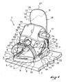
- a reception device 1 allows temporary reception on a board 2 of a shoe not shown.
- the reception device 1 comprises a seat 3 which extends in length between a rear end 4 and a front end 5, and in width from a first edge 6 to a second edge 7.
- the seat 3 has an upper face 8 provided to be facing the sole of the shoe, and a lower face 9 provided to be above the board 2.
- the seat 3 preferably comprises a base 10 covered with a cushion 11.
- the base 10 is a rigid part which delimits at least part of the lower face 9.
- the cushion 11 meanwhile delimits at least part of the face 8.
- the cushion 11 extends from the rear end 4 to the front end 5 of the seat 3. This allows a cushioned contact with the entire surface of the sole of the shoe .
- a rear portion 12 and a front portion 13 of the cushion 11 define a housing space 14 for the base 10.
- the seat 3 can be provided other structures for the seat 3, such as a base associated with two cushions, one at the back, the other at the front.
- the seat 3 is retained in the board 2 by a means represented in the form of a disc 15, itself retained in the board 2 by screws 16.
- the seat 3 is bordered laterally by a first flange 20 and a second flange 21.
- first flange 20 is lateral and the second 21 is medial, but it could have been the opposite.
- Each of the flanges 20, 21 respectively form a lateral or medial part of the device 1 to define a reception zone 22 of the shoe.
- the flanges 20, 21 along the sole laterally.
- stops might be suitable.
- the base 10 and the flanges 20, 21 form a one-piece piece made for example of synthetic material.
- the flanges 20, 21 are parts secured to the base by any means such as gluing, welding, screwing, interlocking, or other.
- the device 1 also comprises a rear support element 23, so that the user can take back supports with the lower leg.
- the rear support member 23 includes a curved plate 24 which extends longitudinally between first and second attachment ends 26 and one end. free 27, transversely between a first edge or side edge 28 and a second edge or medial edge 29, and in thickness between a bearing face 30 and a free face 31.
- bearing face 30 is provided to receive the rear of the lower leg of the user, the rear support member 23 and the base 10 being associated accordingly.
- the rear support element 23 is rotatably mounted relative to the seat 3.
- the rear support element is connected to the flanges 20, 21 by means of a first hinge 32, located at the first attachment end 25, and by means of a second hinge 33, located at the second attachment end 26.
- Each hinge 32, 33 is respectively oriented substantially along a first 34 and a second transverse axis of the device 1.
- Each hinge 32, 33 may comprise any component such as a screw, a rivet, a washer, a nut, a trunnion, or the like.
- Each joint 32, 33 allows a rotational movement of the rear support member 23 to the seat 3.
- a benefit that arises is to facilitate storage.
- a stop 40 limits the rearward rotation of the eponymous support element 23.
- the stop 40 comprises a link 41 which bypasses the rear support element 23.
- the link 41 is disposed on the seat 3 and cooperates with the rear support element 23 to limit the rotation towards the rear of the rear support element 23.
- the path of the link 41 can be observed on the Figures 1 to 5 .
- the link 41 comprises a first portion or side portion 42 and a second portion or medial portion 43, one extending the other.
- Each portion 42, 43 of the link 41 is connected to the base 10 respectively by a first 44 and a second 45 low link, which 44, 45 are each located in front of the first 32 or second 33 articulation.
- the link 41 is preferably made from a cable, the latter having a first end or lateral end 46, and a second end or medial end 47. Each end 46, 47 is connected to the lateral flange 20 or medial 21 by any means known to those skilled in the art, to form the first 44 and second 45 low links. The use of a crimped tip may be suitable. Between the low links 44, 45, the cable 41 follows each flange 20, 21 away from it, to bypass the rear support member 23 in a position further away from the flanges.
- first portion 42 and the second portion 43 are each connected to the rear support member 23 by a first 48 and a second 49 high link, which are located respectively between the first 25 or second 26 attachment end and the free end 27.
- the upper links 48, 49 each comprise a first 50 and a second guide 51.
- the means is formed for example in the form of a shim 52, secured to the element d rear support 23 on the side of the free face 31.
- the wedge 52 located between the guides 50, 51, holds the cable 41. It is sufficient to move the wedge 52 closer to or away from the free end 27.
- any immobilization means known to those skilled in the art is suitable.
- the means may comprise a screw 53 for tightening or loosening the shim 52 relative to the rear support element 23. Additional teeth of the shim 52 and the rear support element 23 allow a positioning of the one on the other. These teeth are well known to those skilled in the art.
- a first link 60 is forward, at the metatarsophalangeal joint when the foot is maintained.
- a second link 61 is located aft, at the instep when the foot is held.
- Each of the links 60, 61 extends transversely between the flanges 20, 21.
- the first link 60 comprises a lateral portion 62 releasably connected to a medial portion 63, by means of a reversible locking device 64.
- the second link 61 comprises a front division 65 and a rear division 66.
- the front division 65 of the link 61 is located on the side of the bearing face 30 of the rear support member 23, and the rear division 66 is located on the side of the free face 31 of the rear support element. This allows the second link 61 to grip the rear support member 23 at the same time it holds the foot or the shoe. It follows that the rear of the lower leg is still pressed against the bearing face 30 of the rear support member 23. A benefit that arises is a direct transmission of the driving pulses during rear support. .
- the rear division 66 of the link 61 comprises a first lateral foot or foot 67 and a second medial foot or foot 68 connected to each other by an arch 69.
- Each of the lateral 67 and medial 68 feet is respectively associated with the flange lateral 20 and medial 21, for example by means of a first articulation or lateral articulation 70 of transverse axis 71, and of a second articulation or medial articulation 72 with transverse axis 73.
- a benefit that derives therefrom is to give the rear division 66 a degree of freedom in rotation along the transverse axes 71, 73. This facilitates the establishment of the rear division 66.
- the arch 69 is more easily plate on the free face 31 of the element d rear support 23.
- the front division 65 is associated with the rear division 66. It is represented as a succession of three portions, which are a first fastening portion 74, a covering portion 75 of the boot, and a second portion of the boot.
- the front division 65 may be reversibly or oppositely squeezed by a reversible locking device 77. The latter is well known to those skilled in the art.
- the position of the rear support member 23 relative to the seat, and therefore relative to the base 10, is longitudinally adjustable.
- the user can therefore choose the longitudinal position of the foot or the shoe , compared to the seat, which suits him. In this way he selects a shoe position that is best for the transmission of sensory information.
- a first 90 and a second 91 carriage for adjusting the longitudinal position of the support member 23.
- the structures and operating modes of the carriages 90, 91 are similar. Also only the first 90 is described in more detail below.
- the first carriage 90 is in the form of an elongate piece. It extends in length from a rear end 92 to a front end 93, in width from an outer face 94 to an inner face 95, and in height from a lower limit 96 to an upper limit 97.
- the first trolley 90 has a U-shaped section, observable in particular on the Figures 6 and 7 . Its exterior 94 and inner 95 faces are perforated by outer windows 98 and inner 99. This structure gives the carriage 90 both a lightness and good mechanical strength.
- the materials used to make it may include metal or synthetic materials, whether or not they are armed. For example, an aluminum alloy is very suitable.
- the first carriage 90 is mounted displaceable longitudinally relative to the first flange 20.
- the carriage 90 is housed in a first longitudinal cavity 110, formed in the first flange 20.
- the first carriage 90 is guided longitudinally in the cavity 110, because this This allows a longitudinal displacement of the carriage 90.
- the cavity 110 has a length substantially greater than that of the carriage 90, but a barely greater width and height.
- Other means of guiding the carriage could be provided, for example the carriage could be guided longitudinally on the flange.
- the establishment of the carriage 90 in the cavity 110 is by insertion on the side of the lower face 9.
- a bottom 111 of the cavity 110 partly perforated by a slot 112, limits the insertion depth of the carriage 90.
- the lug 113 is an outgrowth of material from the first flange 20. The lug 113 moves elastically to the setting place of the carriage 90, to lodge in the outer window 98.
- a means for indexing the position of the carriage 90 along the longitudinal cavity 110.
- This means comprises, for example, ridges 114 arranged vertically on the outer face 94, as well as an internal boss 115 arranged in the cavity 110.
- the boss 115 and the striations 114 act so conjugate, to create one or more hard points during the sliding of the carriage 90 in the cavity 110.
- the indexing means makes it possible to position the carriage 90 more easily.
- an adjusting means comprises, for example, three orifices 120, 121, 122 formed in the outer face 94, as well as a screw 123.
- the screw 123 is screwed into the longitudinal cavity 110 to fit into one of the three orifices 120, 121, 122.
- the adjustment operation consists of unscrewing the screw 123, manually moving the carriage, and then screwing the screw 123 to partially fill at least one of the orifices 120, 121, 122.
- the indexing and adjusting means coordinate their effects. This means that when an orifice 120, 121, 122 of the adjustment means is occupied by the screw 123, the boss 115 of the cavity 110 is embedded in a groove 114 of the carriage 90.
- the first attachment end 25 of the rear support element 23 is connected to the first carriage 90 by the first articulation 32 of transverse axis 34.
- the hinge 32 has a circular orifice 124 formed in the inner face 95, near the rear end 92.
- the first hinge 32 also comprises a pin 125.
- the rear support element 23 is connected to the first flange 20 via the first carriage 90.
- the connection of the rear support element 23 to the flange 20, and therefore to the seat 3, is therefore an indirect connection, the carriage 90 carrying the first attachment end 25 of the rear support element 23.
- the second carriage 91 is guided longitudinally in a cavity 130 of the second flange 21.
- the second attachment end 26 of the rear support element 23 is connected to the second carriage 91 by the second articulation 33 with transverse axis 35.
- the rear support element 23 is connected to the second flange 21 via the second carriage 91.
- the connection of the rear support element 23 to the flange 21, and therefore to the seat 3, is an indirect connection, the carriage 91 carrying the second attachment end 26 of the rear support element 23.
- the figures 4 , 5 and 9 correspond to situations for which the trolleys 90, 91 are substantially vis-à-vis. Their longitudinal positions are the same. As a result, the first 25 and second 26 attachment ends face each other in a transverse direction of the device. It follows that the rear support element 23 is substantially centered on the rear of the lower leg, when it is in the device 1. This allows the user to take precise support in a longitudinal direction back. In a case where the device 1 is oriented transversely relative to the board 2, the edge grip is easier because the forces are oriented perpendicularly to the board 2.
- the user can bring the rear support element 23 forwardly according to the figure 4 , or backwards according to the figure 5 , in an intermediate position according to the figure 9 .
- the Device 1 is adjustable in length. This allows the user to consider its size, weight, shoe size, driving style, or snow quality.
- FIG. 10 corresponds to a situation for which the trolleys 90, 91 are offset longitudinally. As a result the first 25 and second 26 attachment ends are shifted. It follows that the rear support element 23 is off-center on the rear of the lower leg, when it is in the device 1. This allows the user to take precise support in a direction offset by relative to the rear longitudinal direction. The user can shift the rear support element 23 to compensate for an offset of the device 1 relative to the board 2. As a result, it can again orient its rear support forces perpendicularly to the board 2.
- the link 41 is connected to the seat 3 indirectly by the low links 44, 45.
- the first end 46 of the first portion 42 of the link 41 is connected to the first carriage 90, preferably at its front end 93.
- the second end 47 of the second portion 43 of the link 41 is connected to the second carriage 91, preferably at its front end . It follows that each of the carriages 90, 91 is bonded to both a fastening end 25, 26 of the rear support member and a link portion 42, 43 41.
- reception device 1 comprises means for moving the rear support element 23 simultaneously with the link 41.
- the invention is made from materials and according to implementation techniques known to those skilled in the art.
- the means for adjusting the longitudinal position of the rear support element are independent of the means for adjusting the longitudinal position of the link 41 of the abutment 40.
- the longitudinal displacement of the rear support element 23 is independent of the link 41.
- the joints 32, 33 which connect the rear support member 23 to the carriages 90, 91 are different from the joints 70, 72 which connect the second link 61 to the flanges 20, 21.
- the link 61 can not move forward or backward.
Landscapes
- Footwear And Its Accessory, Manufacturing Method And Apparatuses (AREA)
Claims (13)
- Vorrichtung zur Aufnahme (1) eines Fußes oder eines Schuhs auf einem Schneegleiter (2), wobei die Vorrichtung (1) eine Auflagefläche (3) umfasst, welche mit einem hinteren Auflagebauteil (23) verbunden ist, wobei sich die Auflagefläche (3) in der Länge von einem hinteren Ende (4) zu einem vorderen Ende (5) erstreckt, und in der Breite von einem ersten Rand (6) zu einem zweiten Rand (7) erstreckt, wobei das hintere Auflagebauteil (23) drehbar in Bezug auf die Auflagefläche (3) montiert ist, eine Verbindung (41) auf der Auflagefläche (3) angeordnet ist, und in Verbindung mit dem hinteren Auflagebauteil (23) ist, um die Drehung nach hinten des hinteren Auflagebauteils (23) zu begrenzen, wobei die Verbindung zumindest eine Führung (50, 51) auf dem hinteren Auflagebauteil (23) umfasst, dadurch gekennzeichnet, dass die Stellung des hinteren Auflagebauteils (23) in Bezug auf die Auflagefläche (3) längs regelbar ist.
- Aufnahmevorrichtung (1) nach Anspruch 1, dadurch gekennzeichnet, dass die LängsVerschiebung des hinteren Auflagebauteils (23) unabhängig von der Verbindung (41) ist.
- Aufnahmevorrichtung (1) nach Anspruch 1, dadurch gekennzeichnet, dass sie Mittel zum Verschieben des hinteren Auflagebauteils (23) simultan mit der Verbindung (41) umfasst.
- Aufnahmevorrichtung (1) nach einem der Ansprüche 1 bis 3, dadurch gekennzeichnet, dass das hintere Auflagebauteil (23) längs auf Höhe zumindest einem (28, 29) seiner Ränder verschoben werden kann.
- Aufnahmevorrichtung (1) nach einem der Ansprüche 1, 3 und 4, dadurch gekennzeichnet, dass die Auflagefläche (3) seitlich von einem ersten Flansch (20) umrandet wird, wobei ein erster Schieber (90) längs verschiebbar in Bezug auf den ersten Flansch (20) befestigt ist, wobei der Schieber (90) ein erstes Befestigungsende (25) des hinteren Auflagebauteils (23) trägt, wobei ein Reglungsmittel dazu vorgesehen ist, die Längsstellung des ersten Schiebers (90) zu regeln.
- Aufnahmevorrichtung (1) nach Anspruch 5, dadurch gekennzeichnet, dass ein erstes Ende (46) eines ersten Abschnitts (42) der Verbindung (41) mit dem ersten Schieber (90) verbunden ist.
- Aufnahmevorrichtung (1) nach einem der Ansprüche 1 und 3 bis 6, dadurch gekennzeichnet, dass die Auflagefläche (3) seitlich von einem zweiten Flansch (21) umrandet wird, wobei ein zweiter Schieber (91) längs verschiebbar in Bezug auf den zweiten Flansch (21) befestigt ist, und wobei der Schieber (91) ein zweites Befestigungsende (26) des hinteren Auflagebauteils (23) trägt, wobei ein Reglungsmittel dazu vorgesehen ist, die Längsstellung des zweiten Schiebers (91) zu regeln.
- Aufnahmevorrichtung (1) nach Anspruch 7, dadurch gekennzeichnet, dass ein zweites Ende (47) eines zweiten Abschnitts (43) der Verbindung (41) mit dem zweiten Schieber (91) verbunden ist.
- Aufnahmevorrichtung (1) nach Anspruch 8, dadurch gekennzeichnet, dass die Verbindung (41) den ersten (42) und den zweiten Abschnitt (43) umfasst, wobei der eine den anderen verlängert, die Verbindung (41) das hintere Auflagebauteil (23) in einer entfernten Stellung der Flansche (20, 21) umrundet.
- Aufnahmevorrichtung (1) nach einem der Ansprüche 5 bis 9, dadurch gekennzeichnet, dass das Reglungsmittel Öffnungen (120, 121, 122) aufweist, welche in der äußeren Fläche (94) von jedem Schieber (90, 91) eingebracht sind, genauso wie eine Schraube (123), welche in den Längshohlraum (110, 130) des Flansches (20, 21) geschraubt ist, um sich in eine der Öffnungen (120,121,122) einzubringen.
- Aufnahmevorrichtung (1) nach einem der Ansprüche 5 bis 10, dadurch gekennzeichnet, dass sie ein Anzeigemittel jedes Schiebers (90, 91) umfasst.
- Aufnahmevorrichtung (1) nach einem der Ansprüche 5 bis 11, dadurch gekennzeichnet, dass sie einen Schlüssel (113) umfasst, welcher einen unangebrachten Ausschlupf des Schiebers (90, 91) aus dem Hohlraum (110, 130) verhindert.
- Aufnahmevorrichtung (1) nach einem der Ansprüche 1 bis 12, dadurch gekennzeichnet, dass er eine zweite Verbindung (61) umfasst, um einen Schuh auf der Auflagefläche (3) zwischen den Flanschen (20, 21), zu halten, wobei die zweite Verbindung (61) einen ersten Fuß (67) aufweist, welcher mit dem ersten Flansch (20) mit Hilfe eines ersten Gelenks (70) einer Querachse (71) verbunden ist, genauso wie einen zweiten Fuß (68), welcher zu dem zweiten Flansch (21) mit Hilfe eines zweiten Gelenks (72) einer Querachse (73) verbunden ist.
Applications Claiming Priority (2)
| Application Number | Priority Date | Filing Date | Title |
|---|---|---|---|
| FR0400903 | 2004-01-30 | ||
| FR0400903A FR2865658B1 (fr) | 2004-01-30 | 2004-01-30 | Dispositif d'accueil d'un pied ou d'une chaussure sur un engin de sport |
Publications (2)
| Publication Number | Publication Date |
|---|---|
| EP1559454A1 EP1559454A1 (de) | 2005-08-03 |
| EP1559454B1 true EP1559454B1 (de) | 2008-06-11 |
Family
ID=34639813
Family Applications (1)
| Application Number | Title | Priority Date | Filing Date |
|---|---|---|---|
| EP05000005A Revoked EP1559454B1 (de) | 2004-01-30 | 2005-01-03 | Schuh- oder Fusshaltevorrichtung an einem Sportgerät |
Country Status (6)
| Country | Link |
|---|---|
| US (1) | US7503579B2 (de) |
| EP (1) | EP1559454B1 (de) |
| CN (1) | CN1647836A (de) |
| AT (1) | ATE397962T1 (de) |
| DE (1) | DE602005007393D1 (de) |
| FR (1) | FR2865658B1 (de) |
Families Citing this family (23)
| Publication number | Priority date | Publication date | Assignee | Title |
|---|---|---|---|---|
| DE10305764B4 (de) * | 2003-02-11 | 2007-04-12 | Goodwell International Ltd., Tortola | Snowboardbindung |
| US8016315B2 (en) * | 2005-09-30 | 2011-09-13 | Flow Sports, Inc. | Modular binding for sports board |
| FR2896425B1 (fr) * | 2006-01-26 | 2008-04-18 | Salomon Sa | Dispositif d'accueil d'un pied ou d'une chaussure sur un engin de sport |
| ATE452690T1 (de) * | 2006-07-07 | 2010-01-15 | Burton Corp | In fussbett integrierter einstellungsindikator für gleitbrettbindung |
| US7686321B2 (en) * | 2006-12-01 | 2010-03-30 | The Burton Corporation | Highback with textile-like material for support |
| US20080258434A1 (en) * | 2007-04-13 | 2008-10-23 | Krenn Thomas | Snowboard binding with rear step-in and securing of boot by toe element |
| US8469372B2 (en) | 2008-10-23 | 2013-06-25 | Bryce M. Kloster | Splitboard binding apparatus |
| WO2010124382A1 (en) | 2009-04-30 | 2010-11-04 | Pelchat Jean-Francois | Binding system for recreational board |
| US9016714B2 (en) | 2009-04-30 | 2015-04-28 | Jf Pelchat Inc. | Binding system for recreational board |
| FR2958556B1 (fr) | 2010-04-12 | 2012-12-21 | Salomon Sas | Dispositif d'accueil d'un pied ou d'une chaussure sur un engin de glisse. |
| ES1074122Y (es) * | 2010-10-22 | 2011-06-24 | Huerta Almansa Asier De | Fijacion giratoria para snowboard |
| US8540271B2 (en) * | 2011-09-15 | 2013-09-24 | Windsor Chou | Snowshoe binding |
| US9238168B2 (en) | 2012-02-10 | 2016-01-19 | Bryce M. Kloster | Splitboard joining device |
| USD689971S1 (en) | 2012-03-15 | 2013-09-17 | NOW Snowboarding Inc. | Snowboard binding |
| US9266010B2 (en) * | 2012-06-12 | 2016-02-23 | Tyler G. Kloster | Splitboard binding with adjustable leverage devices |
| US9114309B1 (en) * | 2014-06-23 | 2015-08-25 | Tzy Shenq Enterprise Co., Ltd. | Fixation seat for ski shoe |
| US9254434B2 (en) | 2014-06-23 | 2016-02-09 | Tzy Shenq Enterprise Co., Ltd. | Fixation seat for ski shoe |
| US9604122B2 (en) | 2015-04-27 | 2017-03-28 | Bryce M. Kloster | Splitboard joining device |
| US10029165B2 (en) | 2015-04-27 | 2018-07-24 | Bryce M. Kloster | Splitboard joining device |
| US10105588B1 (en) * | 2017-09-26 | 2018-10-23 | Chasen Massey | Snowboard binding with adjustment memory |
| US11117042B2 (en) | 2019-05-03 | 2021-09-14 | Bryce M. Kloster | Splitboard binding |
| DE102021100829B3 (de) | 2021-01-15 | 2022-05-19 | ReActive Robotics GmbH | Fußstützensystem für ein Fußmodul eines Rehabilitationsmechanismus |
| US11938394B2 (en) | 2021-02-22 | 2024-03-26 | Bryce M. Kloster | Splitboard joining device |
Family Cites Families (13)
| Publication number | Priority date | Publication date | Assignee | Title |
|---|---|---|---|---|
| DE2553885C3 (de) * | 1975-11-29 | 1978-07-06 | Heinrich Wunder Kg, 8060 Dachau | Trittgestell für Tourenbindungen |
| US4473235A (en) * | 1982-01-19 | 1984-09-25 | Burt Lionel J | Apparatus for improved control of skis |
| US5261689A (en) * | 1992-01-28 | 1993-11-16 | Burton Corporation Usa | Snowboard boot binding system |
| US5692765A (en) * | 1995-06-07 | 1997-12-02 | Laughlin; James | Soft boot step-in snowboard binding |
| DE29700632U1 (de) * | 1997-01-17 | 1997-06-05 | Marker Deutschland Gmbh | Snowboard-Bindung |
| FR2745692B1 (fr) * | 1996-03-06 | 1998-05-29 | Salomon Sa | Insert pour chaussure destinee a la pratique du surf sur neige |
| FR2758468A1 (fr) * | 1997-01-17 | 1998-07-24 | Fin S International | Dispositif de fixation de chaussure pour article de sport de glisse |
| US6283482B1 (en) * | 1998-12-07 | 2001-09-04 | The Burton Corporation | Binding with a tool-free selectively adjustable leg support member |
| FR2801514B1 (fr) * | 1999-11-25 | 2001-12-21 | Rossignol Sa | Fixation de surf |
| FR2817163B1 (fr) * | 2000-11-24 | 2003-02-21 | Salomon Sa | Ensemble de retenue d'une chaussure sur une planche |
| JP4013487B2 (ja) * | 2001-02-28 | 2007-11-28 | 株式会社日立製作所 | 回転電機及びそれを搭載した車両 |
| US6722688B2 (en) * | 2001-11-21 | 2004-04-20 | The Burton Corporation | Snowboard binding system |
| DE10305764B4 (de) * | 2003-02-11 | 2007-04-12 | Goodwell International Ltd., Tortola | Snowboardbindung |
-
2004
- 2004-01-30 FR FR0400903A patent/FR2865658B1/fr not_active Expired - Fee Related
-
2005
- 2005-01-03 EP EP05000005A patent/EP1559454B1/de not_active Revoked
- 2005-01-03 AT AT05000005T patent/ATE397962T1/de not_active IP Right Cessation
- 2005-01-03 DE DE602005007393T patent/DE602005007393D1/de not_active Expired - Lifetime
- 2005-01-21 US US11/038,080 patent/US7503579B2/en not_active Expired - Fee Related
- 2005-01-27 CN CNA2005100058145A patent/CN1647836A/zh active Pending
Also Published As
| Publication number | Publication date |
|---|---|
| ATE397962T1 (de) | 2008-07-15 |
| US7503579B2 (en) | 2009-03-17 |
| FR2865658A1 (fr) | 2005-08-05 |
| DE602005007393D1 (de) | 2008-07-24 |
| EP1559454A1 (de) | 2005-08-03 |
| FR2865658B1 (fr) | 2006-06-09 |
| CN1647836A (zh) | 2005-08-03 |
| US20050167933A1 (en) | 2005-08-04 |
Similar Documents
| Publication | Publication Date | Title |
|---|---|---|
| EP1559454B1 (de) | Schuh- oder Fusshaltevorrichtung an einem Sportgerät | |
| EP1512440B1 (de) | Schuh- oder Fusshaltevorrichtung an einem Sportgerät | |
| EP1120139A1 (de) | Trägerplatte für Sportgerät | |
| CA2817349A1 (fr) | Crampon pour chaussure | |
| EP1254684B1 (de) | Verbesserte Kupplung eines Stiefels an ein Snowboard | |
| EP1108450B1 (de) | Vorrichtung zur Halterung eines Schuhs auf einem Gleitbrett | |
| EP0637981B1 (de) | Snowboard | |
| EP0933100B1 (de) | Bindung für einen Schuh an einem Snowboard | |
| FR2835439A1 (fr) | Fixation pour appareils de sport, notamment pour une planche de surf des neiges | |
| FR2896425A1 (fr) | Dispositif d'accueil d'un pied ou d'une chaussure sur un engin de sport | |
| FR2858940A1 (fr) | Fixation de surf des neiges | |
| FR2958556A1 (fr) | Dispositif d'accueil d'un pied ou d'une chaussure sur un engin de glisse. | |
| EP1104251A1 (de) | Langlaufskischuh | |
| EP1439890A1 (de) | Rückhaltevorrichtung für einen schuh auf einem gleitbrett | |
| EP2052764A2 (de) | Anordnung zum Praktizieren eines Gleit- oder Rollsports | |
| EP3708230B1 (de) | Haltevorrichtung für gleitbrette | |
| EP1433504A1 (de) | Vorrichtung zum Befestigen eines Schuhs auf einem Sportgerät | |
| FR2666201A1 (fr) | Chaussure de sport, notamment pour la pratique du ski de fond. | |
| EP1512441B1 (de) | Schuh- oder Fusshaltevorrichtung an einem Sportgerät | |
| EP0753330B1 (de) | Übungsmittel zum Erlernen des Skilanglaufs nach der Schlittschuhlaufschritttechnik | |
| FR2810253A1 (fr) | Raquette a neige | |
| EP1923105B1 (de) | Vorrichtung zur Aufnahme eines Fußes oder eines Schuhs auf einem Sportgerät | |
| WO1998015326A1 (fr) | Patin a roulettes en ligne | |
| EP1468711A1 (de) | Vorrichtung zum Befestigen eines Schuhs auf einem Sportgerät | |
| FR2721526A1 (fr) | Planche de glisse pourvue d'une plaque de surélévation des fixations de la chaussure. |
Legal Events
| Date | Code | Title | Description |
|---|---|---|---|
| PUAI | Public reference made under article 153(3) epc to a published international application that has entered the european phase |
Free format text: ORIGINAL CODE: 0009012 |
|
| AK | Designated contracting states |
Kind code of ref document: A1 Designated state(s): AT BE BG CH CY CZ DE DK EE ES FI FR GB GR HU IE IS IT LI LT LU MC NL PL PT RO SE SI SK TR |
|
| AX | Request for extension of the european patent |
Extension state: AL BA HR LV MK YU |
|
| 17P | Request for examination filed |
Effective date: 20051212 |
|
| AKX | Designation fees paid |
Designated state(s): AT BE BG CH CY CZ DE DK EE ES FI FR GB GR HU IE IS IT LI LT LU MC NL PL PT RO SE SI SK TR |
|
| GRAP | Despatch of communication of intention to grant a patent |
Free format text: ORIGINAL CODE: EPIDOSNIGR1 |
|
| GRAS | Grant fee paid |
Free format text: ORIGINAL CODE: EPIDOSNIGR3 |
|
| GRAA | (expected) grant |
Free format text: ORIGINAL CODE: 0009210 |
|
| AK | Designated contracting states |
Kind code of ref document: B1 Designated state(s): AT BE BG CH CY CZ DE DK EE ES FI FR GB GR HU IE IS IT LI LT LU MC NL PL PT RO SE SI SK TR |
|
| REG | Reference to a national code |
Ref country code: GB Ref legal event code: FG4D Free format text: NOT ENGLISH |
|
| REG | Reference to a national code |
Ref country code: CH Ref legal event code: EP |
|
| REF | Corresponds to: |
Ref document number: 602005007393 Country of ref document: DE Date of ref document: 20080724 Kind code of ref document: P |
|
| REG | Reference to a national code |
Ref country code: IE Ref legal event code: FG4D Free format text: LANGUAGE OF EP DOCUMENT: FRENCH |
|
| PG25 | Lapsed in a contracting state [announced via postgrant information from national office to epo] |
Ref country code: SI Free format text: LAPSE BECAUSE OF FAILURE TO SUBMIT A TRANSLATION OF THE DESCRIPTION OR TO PAY THE FEE WITHIN THE PRESCRIBED TIME-LIMIT Effective date: 20080611 Ref country code: FI Free format text: LAPSE BECAUSE OF FAILURE TO SUBMIT A TRANSLATION OF THE DESCRIPTION OR TO PAY THE FEE WITHIN THE PRESCRIBED TIME-LIMIT Effective date: 20080611 |
|
| PG25 | Lapsed in a contracting state [announced via postgrant information from national office to epo] |
Ref country code: NL Free format text: LAPSE BECAUSE OF FAILURE TO SUBMIT A TRANSLATION OF THE DESCRIPTION OR TO PAY THE FEE WITHIN THE PRESCRIBED TIME-LIMIT Effective date: 20080611 Ref country code: AT Free format text: LAPSE BECAUSE OF FAILURE TO SUBMIT A TRANSLATION OF THE DESCRIPTION OR TO PAY THE FEE WITHIN THE PRESCRIBED TIME-LIMIT Effective date: 20080611 Ref country code: PL Free format text: LAPSE BECAUSE OF FAILURE TO SUBMIT A TRANSLATION OF THE DESCRIPTION OR TO PAY THE FEE WITHIN THE PRESCRIBED TIME-LIMIT Effective date: 20080611 |
|
| NLV1 | Nl: lapsed or annulled due to failure to fulfill the requirements of art. 29p and 29m of the patents act | ||
| PG25 | Lapsed in a contracting state [announced via postgrant information from national office to epo] |
Ref country code: LT Free format text: LAPSE BECAUSE OF FAILURE TO SUBMIT A TRANSLATION OF THE DESCRIPTION OR TO PAY THE FEE WITHIN THE PRESCRIBED TIME-LIMIT Effective date: 20080611 Ref country code: PT Free format text: LAPSE BECAUSE OF FAILURE TO SUBMIT A TRANSLATION OF THE DESCRIPTION OR TO PAY THE FEE WITHIN THE PRESCRIBED TIME-LIMIT Effective date: 20081111 Ref country code: ES Free format text: LAPSE BECAUSE OF FAILURE TO SUBMIT A TRANSLATION OF THE DESCRIPTION OR TO PAY THE FEE WITHIN THE PRESCRIBED TIME-LIMIT Effective date: 20080922 Ref country code: SE Free format text: LAPSE BECAUSE OF FAILURE TO SUBMIT A TRANSLATION OF THE DESCRIPTION OR TO PAY THE FEE WITHIN THE PRESCRIBED TIME-LIMIT Effective date: 20080911 Ref country code: IS Free format text: LAPSE BECAUSE OF FAILURE TO SUBMIT A TRANSLATION OF THE DESCRIPTION OR TO PAY THE FEE WITHIN THE PRESCRIBED TIME-LIMIT Effective date: 20081011 Ref country code: CZ Free format text: LAPSE BECAUSE OF FAILURE TO SUBMIT A TRANSLATION OF THE DESCRIPTION OR TO PAY THE FEE WITHIN THE PRESCRIBED TIME-LIMIT Effective date: 20080611 |
|
| REG | Reference to a national code |
Ref country code: IE Ref legal event code: FD4D |
|
| PG25 | Lapsed in a contracting state [announced via postgrant information from national office to epo] |
Ref country code: SK Free format text: LAPSE BECAUSE OF FAILURE TO SUBMIT A TRANSLATION OF THE DESCRIPTION OR TO PAY THE FEE WITHIN THE PRESCRIBED TIME-LIMIT Effective date: 20080611 Ref country code: RO Free format text: LAPSE BECAUSE OF FAILURE TO SUBMIT A TRANSLATION OF THE DESCRIPTION OR TO PAY THE FEE WITHIN THE PRESCRIBED TIME-LIMIT Effective date: 20080611 |
|
| PLBI | Opposition filed |
Free format text: ORIGINAL CODE: 0009260 |
|
| PLAX | Notice of opposition and request to file observation + time limit sent |
Free format text: ORIGINAL CODE: EPIDOSNOBS2 |
|
| 26 | Opposition filed |
Opponent name: FLOW SPORTS, INC. Effective date: 20090311 |
|
| PG25 | Lapsed in a contracting state [announced via postgrant information from national office to epo] |
Ref country code: BG Free format text: LAPSE BECAUSE OF FAILURE TO SUBMIT A TRANSLATION OF THE DESCRIPTION OR TO PAY THE FEE WITHIN THE PRESCRIBED TIME-LIMIT Effective date: 20080911 Ref country code: IE Free format text: LAPSE BECAUSE OF FAILURE TO SUBMIT A TRANSLATION OF THE DESCRIPTION OR TO PAY THE FEE WITHIN THE PRESCRIBED TIME-LIMIT Effective date: 20080611 Ref country code: EE Free format text: LAPSE BECAUSE OF FAILURE TO SUBMIT A TRANSLATION OF THE DESCRIPTION OR TO PAY THE FEE WITHIN THE PRESCRIBED TIME-LIMIT Effective date: 20080611 Ref country code: DK Free format text: LAPSE BECAUSE OF FAILURE TO SUBMIT A TRANSLATION OF THE DESCRIPTION OR TO PAY THE FEE WITHIN THE PRESCRIBED TIME-LIMIT Effective date: 20080611 |
|
| PLAB | Opposition data, opponent's data or that of the opponent's representative modified |
Free format text: ORIGINAL CODE: 0009299OPPO |
|
| PG25 | Lapsed in a contracting state [announced via postgrant information from national office to epo] |
Ref country code: IT Free format text: LAPSE BECAUSE OF FAILURE TO SUBMIT A TRANSLATION OF THE DESCRIPTION OR TO PAY THE FEE WITHIN THE PRESCRIBED TIME-LIMIT Effective date: 20080611 Ref country code: MC Free format text: LAPSE BECAUSE OF NON-PAYMENT OF DUE FEES Effective date: 20090131 |
|
| PLBB | Reply of patent proprietor to notice(s) of opposition received |
Free format text: ORIGINAL CODE: EPIDOSNOBS3 |
|
| GBPC | Gb: european patent ceased through non-payment of renewal fee |
Effective date: 20090103 |
|
| PG25 | Lapsed in a contracting state [announced via postgrant information from national office to epo] |
Ref country code: GB Free format text: LAPSE BECAUSE OF NON-PAYMENT OF DUE FEES Effective date: 20090103 |
|
| REG | Reference to a national code |
Ref country code: CH Ref legal event code: PFA Owner name: SALOMON S.A.S. Free format text: SALOMON S.A.#LIEUDIT "LA RAVOIRE"#74370 METZ-TESSY (FR) -TRANSFER TO- SALOMON S.A.S.#LES CROISELETS#74370 METZ-TESSY (FR) |
|
| PG25 | Lapsed in a contracting state [announced via postgrant information from national office to epo] |
Ref country code: BE Free format text: LAPSE BECAUSE OF NON-PAYMENT OF DUE FEES Effective date: 20090131 |
|
| REG | Reference to a national code |
Ref country code: FR Ref legal event code: CJ Ref country code: FR Ref legal event code: CA |
|
| PG25 | Lapsed in a contracting state [announced via postgrant information from national office to epo] |
Ref country code: GR Free format text: LAPSE BECAUSE OF FAILURE TO SUBMIT A TRANSLATION OF THE DESCRIPTION OR TO PAY THE FEE WITHIN THE PRESCRIBED TIME-LIMIT Effective date: 20080912 |
|
| PG25 | Lapsed in a contracting state [announced via postgrant information from national office to epo] |
Ref country code: LU Free format text: LAPSE BECAUSE OF NON-PAYMENT OF DUE FEES Effective date: 20090103 |
|
| PGFP | Annual fee paid to national office [announced via postgrant information from national office to epo] |
Ref country code: CH Payment date: 20110112 Year of fee payment: 7 Ref country code: DE Payment date: 20101230 Year of fee payment: 7 Ref country code: FR Payment date: 20110128 Year of fee payment: 7 |
|
| PG25 | Lapsed in a contracting state [announced via postgrant information from national office to epo] |
Ref country code: HU Free format text: LAPSE BECAUSE OF FAILURE TO SUBMIT A TRANSLATION OF THE DESCRIPTION OR TO PAY THE FEE WITHIN THE PRESCRIBED TIME-LIMIT Effective date: 20081212 |
|
| PG25 | Lapsed in a contracting state [announced via postgrant information from national office to epo] |
Ref country code: TR Free format text: LAPSE BECAUSE OF FAILURE TO SUBMIT A TRANSLATION OF THE DESCRIPTION OR TO PAY THE FEE WITHIN THE PRESCRIBED TIME-LIMIT Effective date: 20080611 |
|
| PG25 | Lapsed in a contracting state [announced via postgrant information from national office to epo] |
Ref country code: CY Free format text: LAPSE BECAUSE OF FAILURE TO SUBMIT A TRANSLATION OF THE DESCRIPTION OR TO PAY THE FEE WITHIN THE PRESCRIBED TIME-LIMIT Effective date: 20080611 |
|
| REG | Reference to a national code |
Ref country code: DE Ref legal event code: R103 Ref document number: 602005007393 Country of ref document: DE Ref country code: DE Ref legal event code: R064 Ref document number: 602005007393 Country of ref document: DE |
|
| PLBP | Opposition withdrawn |
Free format text: ORIGINAL CODE: 0009264 |
|
| RDAF | Communication despatched that patent is revoked |
Free format text: ORIGINAL CODE: EPIDOSNREV1 |
|
| RDAG | Patent revoked |
Free format text: ORIGINAL CODE: 0009271 |
|
| STAA | Information on the status of an ep patent application or granted ep patent |
Free format text: STATUS: PATENT REVOKED |
|
| REG | Reference to a national code |
Ref country code: CH Ref legal event code: PL |
|
| 27W | Patent revoked |
Effective date: 20111123 |
|
| REG | Reference to a national code |
Ref country code: DE Ref legal event code: R107 Ref document number: 602005007393 Country of ref document: DE Effective date: 20120712 |
|
| PG25 | Lapsed in a contracting state [announced via postgrant information from national office to epo] |
Ref country code: CH Free format text: LAPSE BECAUSE OF THE APPLICANT RENOUNCES Effective date: 20080611 Ref country code: LI Free format text: LAPSE BECAUSE OF THE APPLICANT RENOUNCES Effective date: 20080611 |