EP1558865B2 - Vanne a gaz - Google Patents
Vanne a gaz Download PDFInfo
- Publication number
- EP1558865B2 EP1558865B2 EP03776795A EP03776795A EP1558865B2 EP 1558865 B2 EP1558865 B2 EP 1558865B2 EP 03776795 A EP03776795 A EP 03776795A EP 03776795 A EP03776795 A EP 03776795A EP 1558865 B2 EP1558865 B2 EP 1558865B2
- Authority
- EP
- European Patent Office
- Prior art keywords
- valve
- gas
- closing member
- gas valve
- valve closing
- Prior art date
- Legal status (The legal status is an assumption and is not a legal conclusion. Google has not performed a legal analysis and makes no representation as to the accuracy of the status listed.)
- Expired - Lifetime
Links
- 238000011144 upstream manufacturing Methods 0.000 claims abstract description 7
- 238000007789 sealing Methods 0.000 claims description 53
- 229920001971 elastomer Polymers 0.000 claims 3
- 239000000806 elastomer Substances 0.000 claims 3
- 239000007789 gas Substances 0.000 description 69
- 210000003734 kidney Anatomy 0.000 description 15
- VNWKTOKETHGBQD-UHFFFAOYSA-N methane Chemical compound C VNWKTOKETHGBQD-UHFFFAOYSA-N 0.000 description 8
- 239000000446 fuel Substances 0.000 description 5
- UFHFLCQGNIYNRP-UHFFFAOYSA-N Hydrogen Chemical compound [H][H] UFHFLCQGNIYNRP-UHFFFAOYSA-N 0.000 description 3
- 229910052739 hydrogen Inorganic materials 0.000 description 3
- 239000001257 hydrogen Substances 0.000 description 3
- 239000003345 natural gas Substances 0.000 description 3
- 230000015572 biosynthetic process Effects 0.000 description 2
- 238000013016 damping Methods 0.000 description 2
- 239000013536 elastomeric material Substances 0.000 description 2
- NJPPVKZQTLUDBO-UHFFFAOYSA-N novaluron Chemical compound C1=C(Cl)C(OC(F)(F)C(OC(F)(F)F)F)=CC=C1NC(=O)NC(=O)C1=C(F)C=CC=C1F NJPPVKZQTLUDBO-UHFFFAOYSA-N 0.000 description 2
- 229920000049 Carbon (fiber) Polymers 0.000 description 1
- 239000004696 Poly ether ether ketone Substances 0.000 description 1
- 229910000831 Steel Inorganic materials 0.000 description 1
- 230000001154 acute effect Effects 0.000 description 1
- JUPQTSLXMOCDHR-UHFFFAOYSA-N benzene-1,4-diol;bis(4-fluorophenyl)methanone Chemical compound OC1=CC=C(O)C=C1.C1=CC(F)=CC=C1C(=O)C1=CC=C(F)C=C1 JUPQTSLXMOCDHR-UHFFFAOYSA-N 0.000 description 1
- 239000004917 carbon fiber Substances 0.000 description 1
- 239000000919 ceramic Substances 0.000 description 1
- 230000006835 compression Effects 0.000 description 1
- 238000007906 compression Methods 0.000 description 1
- 230000003628 erosive effect Effects 0.000 description 1
- 238000005530 etching Methods 0.000 description 1
- 239000012530 fluid Substances 0.000 description 1
- 238000009434 installation Methods 0.000 description 1
- 239000007788 liquid Substances 0.000 description 1
- 230000001050 lubricating effect Effects 0.000 description 1
- 239000000463 material Substances 0.000 description 1
- 238000000034 method Methods 0.000 description 1
- 239000004033 plastic Substances 0.000 description 1
- 229920002530 polyetherether ketone Polymers 0.000 description 1
- 230000001681 protective effect Effects 0.000 description 1
- 230000035939 shock Effects 0.000 description 1
- 239000010959 steel Substances 0.000 description 1
- 239000002966 varnish Substances 0.000 description 1
Images

Classifications
-
- F—MECHANICAL ENGINEERING; LIGHTING; HEATING; WEAPONS; BLASTING
- F16—ENGINEERING ELEMENTS AND UNITS; GENERAL MEASURES FOR PRODUCING AND MAINTAINING EFFECTIVE FUNCTIONING OF MACHINES OR INSTALLATIONS; THERMAL INSULATION IN GENERAL
- F16K—VALVES; TAPS; COCKS; ACTUATING-FLOATS; DEVICES FOR VENTING OR AERATING
- F16K1/00—Lift valves or globe valves, i.e. cut-off apparatus with closure members having at least a component of their opening and closing motion perpendicular to the closing faces
- F16K1/30—Lift valves or globe valves, i.e. cut-off apparatus with closure members having at least a component of their opening and closing motion perpendicular to the closing faces specially adapted for pressure containers
- F16K1/301—Lift valves or globe valves, i.e. cut-off apparatus with closure members having at least a component of their opening and closing motion perpendicular to the closing faces specially adapted for pressure containers only shut-off valves, i.e. valves without additional means
- F16K1/302—Lift valves or globe valves, i.e. cut-off apparatus with closure members having at least a component of their opening and closing motion perpendicular to the closing faces specially adapted for pressure containers only shut-off valves, i.e. valves without additional means with valve member and actuator on the same side of the seat
-
- F—MECHANICAL ENGINEERING; LIGHTING; HEATING; WEAPONS; BLASTING
- F16—ENGINEERING ELEMENTS AND UNITS; GENERAL MEASURES FOR PRODUCING AND MAINTAINING EFFECTIVE FUNCTIONING OF MACHINES OR INSTALLATIONS; THERMAL INSULATION IN GENERAL
- F16K—VALVES; TAPS; COCKS; ACTUATING-FLOATS; DEVICES FOR VENTING OR AERATING
- F16K39/00—Devices for relieving the pressure on the sealing faces
- F16K39/02—Devices for relieving the pressure on the sealing faces for lift valves
- F16K39/022—Devices for relieving the pressure on the sealing faces for lift valves using balancing surfaces
Definitions
- the invention is based on a gas valve, in particular of a gas valve with electromagnetic actuation, according to the closer defined in the preamble of claim 1.
- Such a gas valve is known from practice and can be used for example as a gas control valve in a fuel cell.
- the known gas valve comprises a valve housing in which a valve closing member is guided axially displaceable, which is connected to an electromagnetic actuator unit.
- the valve closing member serves to control a gas flow from an inlet side to an outlet side and cooperates for this purpose with a valve seat which is formed on a valve plate.
- the inflow side is connected to a pressure region surrounding the valve closure member.
- a sealing collar On the front side of the valve closure member, a sealing collar is usually formed, which rests on a sealing plate with a closed valve closing member and surrounds a cylindrical bore of the sealing plate.
- gases such as hydrogen or methane have lower density compared to liquid fuels. Therefore, in gases often a much larger volume flow is required, so that in a gas valve, a large flow area is desirable at the valve seat.
- the valve lift is limited because of the high dynamics of the valve, with the result that the sealing seat is variable in terms of its diameter substantially. An enlargement of the sealing seat but leads to an increase in the applied opening force or magnetic force, which in turn has an increased power consumption.
- the diameter of the sealing seat can not be chosen arbitrarily large due to a frequently limited installation space. For these reasons, the volume flows or mass flows of the flowing gas are often not sufficiently large for the requirements prevailing in gas engines and fuel cell drives.
- the gas valve according to the invention having the features according to the preamble of claim 1, wherein the upstream side is connected to an inner and an outer pressure region, which pressure regions are arranged upstream of the valve seat, wherein the inner pressure region comprises an axial pressure channel of the valve closure member, the axially exits at the free end face of the valve closure member, and the outer pressure region surrounds the valve closure member, has the advantage that the valve closure member is actuated with little effort, as in its opening in the inner and in the outer pressure region substantially the same pressure prevails and off gas flows in the direction of the throughflow opening at both pressure ranges. This has the advantage over a gas valve according to the prior art that a particular electromagnetic actuator unit for the valve closure member with lower power is interpretable.
- a valve according to the prior art is from the document US 2002/0074532 known.
- This valve has an axial pressure channel with a lateral outlet and an outer pressure region which partially surrounds the valve closure member.
- This Merkmake causes a power imbalance.
- the gas valve according to the invention is a valve which operates according to the pressure compensation principle, allows high mass flows and requires only small forces to actuate the valve closure member.
- the gas valve according to the invention is particularly suitable for mass flow control of gases such as hydrogen and natural gas and can be used for example in a fuel cell.
- the gas valve according to the invention is expediently designed such that the valve closure member has an end face designed as an annular surface sealing surface. When the valve closing member is closed, the sealing surface covers the at least one throughflow opening.
- the inner pressure region is connected to the outer pressure region via at least one outflow channel formed in the valve closure member.
- the outflow channel is formed as a radially aligned bore of the valve closure member, but may also be inclined with a certain angle of attack in the flow direction relative to an axis of the valve closure member and lead from serving as a supply channel axial bore to the outside of the valve closure member.
- the supply channel then also opens into an axial bore of possibly reduced diameter, which represents the inner pressure region or is a part thereof.
- the valve plate has at least two flow openings, which can be covered by means of the sealing surface are.
- the valve plate may also have four flow holes.
- the flow openings are arranged along a circular line whose radius corresponds approximately to the mean radius of the sealing surface.
- the flow-through openings can be designed as kidney-shaped or lenticular openings or as nozzles arranged along the circumference.
- a throttle bore or nozzle formed, for example, on the sealing plate downstream of the apertures or channels and upstream of the downstream side, whose dimensions determine the gas quantity flowing to the downstream side. If, for example, a pressure of about 8 bar prevails in the inner and the outer pressure region, this pressure acts on opening of the valve closing member through the lenticular apertures up to the throttle bore. By means of the throttle bore, the pressure is reduced to, for example, 1 bar.
- a central bore of the gas valve which represents a dead volume space is usually arranged downstream from where the gas in question flows via the throttle bore at sonic or supersonic velocity to the downstream side.
- the latter can form a damping chamber or lead to the atmosphere.
- the transverse surface of the throttle bore arranged downstream of the dead volume space is preferably smaller by a factor of 2.0 to 2.5 than the area of the flow-through openings designed as kidney-shaped or lenticular breaches in order to avoid an influence of pressure surges on the sealing seat.
- the time required for filling the dead volume space can be reduced by arranging on the sealing plate a preferably conically shaped shoulder or pedestal which protrudes into the dead volume space.
- the paragraph further reduces the formation of flow vortices, which can occur when opening the valve closure member, especially in small valve strokes, by detachment of the gas flow.
- the sealing plate may be made of different materials, such as steel, PEEK with carbon fibers, a hard plastic or a ceramic, for example after an etching, an erosion or a laser process.
- the gas valve according to the invention may comprise an elastomeric seal for increasing the seal on the valve seat. This is expediently arranged on the sealing surface lying on the end face of the valve closing member and may have one or more sealing lips.
- the elastomeric seal is annular and embedded in the valve closure member at the end face in a corresponding annular groove. It can be provided with two sealing lips, one of which is arranged on the inner edge of the sealing ring and thus associated with the inner pressure region and the other arranged on the outer edge of the sealing ring and thus associated with the outer pressure range.
- the gas valve according to the invention may have a base serving as a stop for the valve closure member. This is formed for example on the valve plate.
- the stopper is a baffle trap and limits the deformation of the elastomeric sealing ring and thus its wear and defines the air gap on a serving for actuation of the valve closure member armature clearly.
- the valve closure member itself forms a protective ring or baffle catcher to protect the sealing ring.
- aprons for supporting the elastomeric seal may be formed on the sealing plate. These skirts, for example, form the edges of the nozzles.
- FIG. 1 a gas valve 10 is shown for use in a fuel cell or a gas engine, which serves to control a hydrogen flow or a NG (natural gas) gas flow.
- NG natural gas
- the gas valve 10 comprises a housing 12 in which a valve closure member 14 is axially displaceably guided in a long, formed by the housing 12 guide, which is in operative connection with an electromagnetic actuator not shown here and coated with a lubricating varnish.
- the valve closing member 14 comprises a first axial bore 16 serving as a supply channel, which is connected to an inflow side of the gas valve 10, not shown here. From the first axial bore 16 branch off four distributed over the circumference of the valve closing member 14 radial bores 18, each forming a radial outlet bore and of which in FIG. 1 three are shown and lead to a so-called outer pressure region 20 which borders on the outside of the valve closure member 14.
- the first axial bore 16 opens into a second, a pressure channel representing axial bore 19, whose diameter is smaller than the diameter of the first axial bore 16 and exits at the free end face 24 of the valve closure member 14.
- the second axial bore 19 of smaller diameter which is an axial outflow bore, forms a so-called inner pressure region 22 or is part of the same.
- gas flows from the first axial bore 16 via the radial outflow bores 18 into the outer pressure region 20 representing a gas chamber and via the axial outflow bore 19 to the free end side 24 of the valve closure member 14.
- Both the inner pressure region 22 and the outer pressure region 20 are arranged upstream of a valve seat 26, which cooperates with the free end face 24 of the valve closing member 14 and is formed on a nozzle plate 28 serving as a sealing plate or sealing seat disc, which cooperates with the valve closing member 14.
- FIG. 2 In the nozzle plate 28 are as FIG. 2 can be taken along a circular line fourteen axially aligned, serving as flow-through nozzles 30 which lead via an annular groove 32 to a downstream side 34 of the gas valve 10 and have a rounded inflow edge with a radius of curvature of 0.05 mm.
- the nozzles 30 are each designed so that the ratio of their length to their diameter is about 0.7. This causes optimum flow behavior of the gas flowing through the nozzles 30.
- the end face 24 of the valve closing member 14 is formed as an annular surface on which an annular seal 36 made of an elastomeric material is embedded.
- the ring seal 36 closes in the closed position of the valve closing member 14, the nozzle 32, so that a gas flow is blocked from the pressure regions 20 and 22 to the downstream side.
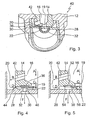
- FIG. 3 a gas valve 40 is shown, which is essentially after that FIG. 1 equivalent.
- the gas valve 40 differs from the gas valve FIG. 1 However, by the formation of the valve closing member 14, in that it is not provided with radially aligned Abströmbohrept, but adjacent to the axial outflow bore 19 at an angle relative to the longitudinal axis of the valve closure member 14 aligned Abströmbohrept 42 which lead to the outer pressure region 20, what a Optimized flow behavior of the gas in question causes.
- the sealing area of the gas valve 40 is in FIG. 4 shown in detail. It is characterized in that the nozzle plate 28 has an optionally annular base 44 which serves as a stop for the valve closing member 14 and is arranged in the edge region of the latter.
- the nozzle plate 28 serving on the nozzle 30 each serving as a sealing lip skirts 46 which engage in the closed valve closure member 14 in the annular elastomeric seal 36 which is embedded in an annular groove of the valve closure member.
- the edges of the elastomeric seal 36 are chamfered and the inflow edges of the nozzles 30 rounded with a radius of curvature of about 0.05 mm.
- the flow of the gas in question in the gas valve 40 is also FIG. 4 refer to.
- the gas flows from the inflow side according to an arrow A through the first axial bore 16 of the valve closing member 14 and from there through the outflow channels 42 according to an arrow B in the outer pressure region 20 and on the other according to an arrow C through the second axial bore 19, the Part of the inner pressure region 22 is.
- opening the valve closing member 14 gas flows from the outer pressure region 20 according to an arrow D and from the inner pressure region 22 according to an arrow E to the nozzle 30 and via this according to an arrow F to the downstream side of the gas valve 40th
- FIG. 5 is an alternative embodiment of a sealing region in a gas valve of the FIG. 3 shown type shown.
- the sealing area after FIG. 5 differs from the one after FIG. 4 in that it comprises a sealing ring 52 which is provided with two sealing lips 54 and 56 which are arranged on the inner or on the outer edge of the sealing ring 52.
- the sealing lips 54 and 56 engage with the valve closing member 14 is closed to the sealing plate 28, which is formed here without stop base and without aprons.
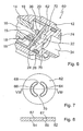
- FIGS. 6 to 8 a further embodiment of a gas valve 60 is shown, which largely according to the gas valve FIG. 1 corresponds to this but differs in that it is not with a nozzle plate but with a trained as a so-called kidney plate sealing plate or sealing seat disc 62 equipped in the FIGS. 7 and 8 is shown in detail.
- the kidney plate 62 serves as a sealing seat for the valve closing member 14 and for the sealing ring embedded therein and in the present case has two kidney-shaped or lenticular apertures or channels 64 and 66, which are arranged along a circular line, the diameter of which substantially mean diameter of the annular end surface 24 of the valve closing member 14 corresponds.
- the openings 64 and 66 are separated from one another by two webs 68 and 70 and open into a central bore 72 which represents a dead volume space and which is formed on a component 74 of the gas valve 60 having the outflow side 34 and which leads to a downstream throttle bore or nozzle 76. by means of which the pressure prevailing at the outflow side 34 is defined. It is also conceivable to provide more than two, for example three or four kidney-shaped openings or channels in the kidney disk 62.
- FIG. 8 it can be seen, have the apertures 64 and 66 rounded inflow edges 67, which are arranged on the facing in the direction of the valve closing member 14 side of the kidney plate 62 and have a radius of curvature of about 0.05 mm.
- valve closing member gas flows from the inner pressure region 22 and the outer pressure region 20 uniformly over the flow area at the sealing seat and the pressure surface provided by the openings 64 and 66 in the dead volume space 62 a. From there, the gas flows via the throttle bore 76 at sonic or supersonic speed to the downstream side 34.
- any compression shocks occurring in the gas valve 60 are displaced to the outflow side 34 forming a damping space and therefore do not occur on the kidney plate 62.
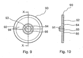
- FIG. 13 is an alternate embodiment of a kidney plate 90 for use with a gas valve of FIG FIG. 6 shown type shown.
- the kidney plate 90 differs from the one in the FIGS. 7 and 8 kidney plate shown in that it has a paragraph or base 91 which projects into the Totvolumenraum 72 and is conical, so that the time required to fill the Totvolumenraums 72 can be shortened.
- the paragraph 91 is used to avoid flow vortices, which can occur when opening the valve closure member, in particular for small valve strokes, by detachment of the gas flow.
- the in FIG. 6 Gas valve may also be provided with a valve closing member, which corresponds to that of the in FIG. 3 Corresponds to the gas valve shown and is therefore provided with outflow holes whose axes are not aligned radially with respect to the longitudinal axis of the valve closure member but include an acute angle with the latter.
- a valve closing member which corresponds to that of the in FIG. 3 Corresponds to the gas valve shown and is therefore provided with outflow holes whose axes are not aligned radially with respect to the longitudinal axis of the valve closure member but include an acute angle with the latter.
- FIG. 6 illustrated gas valve with a sealing area of in FIG. 4 or 5 be provided type shown. It may therefore have a serving as a stop base, which is formed on the sealing seat plate or kidney plate or on the valve closure member and / or is provided with a sealing ring of an elastomeric material, which may be provided with sealing lips or may be formed plan.
- the edges 67 are preferably bevelled or rounded to
Landscapes
- Engineering & Computer Science (AREA)
- General Engineering & Computer Science (AREA)
- Mechanical Engineering (AREA)
- Lift Valve (AREA)
- Magnetically Actuated Valves (AREA)
- Check Valves (AREA)
Abstract
Claims (13)
- Vanne à gaz, en particulier à actionnement électromagnétique, comprenant un obturateur de vanne (14) qui commande un flux de gaz depuis un côté d'amenée jusqu'à un côté de sortie (34) et qui coopère avec un siège de vanne (26) formé sur une plaque de vanne (28, 62, 90) pourvue d'au moins une ouverture de passage d'écoulement (30 ; 64, 66) qui conduit vers le côté de sortie (34), le côté d'amenée étant relié en aval avec une région de pression interne (22) et avec une région de pression externe (20), ces deux régions de pression (20, 22) étant disposées en amont du siège de vanne (26), la région de pression interne (22) comportant un canal de pression axial (19) de l'obturateur de vanne (14) qui débouche axialement au niveau de la face avant libre (24) de l'obturateur de vanne (14), et la région de pression externe (20) entourant l'obturateur de vanne (14),
caractérisée en ce que
l'obturateur de vanne (14) comprend un premier alésage axial (16) servant de canal d'amenée, depuis lequel au moins un alésage radial (18) part perpendiculairement ou au moins suivant un certain angle par rapport à l'axe longitudinal de l'obturateur de vanne (14) sous forme d'alésage d'écoulement (42) vers la région de pression externe (20), et le premier alésage axial (16) débouche dans la direction axiale dans un deuxième alésage axial (19) qui constitue le canal de pression axial (19) allant vers la région de pression interne (22). - Vanne à gaz selon la revendication 1, caractérisée en ce que l'obturateur de vanne (14) présente, sur la face frontale, une surface d'étanchéité réalisée sous forme de surface annulaire.
- Vanne à gaz selon la revendication 1 ou 2, caractérisée en ce que la région de pression interne (22) est raccordée par le biais d'au moins un canal d'écoulement (18) réalisé dans l'obturateur de vanne (14) à la région de pression externe (20).
- Vanne à gaz selon l'une quelconque des revendications 1 à 3, caractérisée en ce que la plaque de vanne (28, 62, 90) présente au moins deux ouvertures de passage d'écoulement (30 ; 64, 66) qui peuvent être recouvertes au moyen de la surface d'étanchéité.
- Vanne à gaz selon la revendication 4, caractérisée en ce que les ouvertures de passage d'écoulement (64, 66) sont réalisées en forme de haricot ou de lentille et conduisent à un espace de volume mort (72).
- Vanne à gaz selon la revendication 4 ou 5, caractérisée en ce qu'en aval des ouvertures de passage d'écoulement (64, 66) et en amont du côté de sortie (34) est disposé un alésage d'étranglement (76).
- Vanne à gaz selon la revendication 5 ou 6, caractérisée en ce qu'un épaulement de préférence conique (91) est réalisé sur la plaque de vanne (90), lequel épaulement pénètre dans l'espace de volume mort (72).
- Vanne à gaz selon la revendication 4, caractérisée en ce que les ouvertures de passage d'écoulement (30) sont réalisées le long d'un cercle sous la forme de buses.
- Vanne à gaz selon l'une quelconque des revendications 1 à 8, caractérisée en ce qu'un joint d'étanchéité élastomère (36, 52) est disposé sur la surface d'étanchéité de l'obturateur de vanne (14).
- Vanne à gaz selon la revendication 9, caractérisée en ce que le joint d'étanchéité élastomère (52) présente au moins une lèvre d'étanchéité (54, 56).
- Vanne à gaz selon l'une quelconque des revendications 1 à 10, caractérisée par un socle (44) servant de butée pour l'obturateur de vanne (14).
- Vanne à gaz selon l'une quelconque des revendications 1 à 11, caractérisée en ce que des jupes (46) sont réalisées sur la plaque de vanne (28) pour venir en prise dans le joint d'étanchéité élastomère (36).
- Vanne à gaz selon l'une quelconque des revendications 1 à 12, caractérisée en ce que le deuxième alésage axial (19) présente dans l'obturateur de vanne (14) un plus petit diamètre que le diamètre du premier alésage axial (16).
Applications Claiming Priority (3)
| Application Number | Priority Date | Filing Date | Title |
|---|---|---|---|
| DE10249964 | 2002-10-26 | ||
| DE2002149964 DE10249964A1 (de) | 2002-10-26 | 2002-10-26 | Gasventil |
| PCT/DE2003/003386 WO2004040176A2 (fr) | 2002-10-26 | 2003-10-13 | Vanne a gaz |
Publications (3)
| Publication Number | Publication Date |
|---|---|
| EP1558865A2 EP1558865A2 (fr) | 2005-08-03 |
| EP1558865B1 EP1558865B1 (fr) | 2008-05-07 |
| EP1558865B2 true EP1558865B2 (fr) | 2011-12-28 |
Family
ID=32087218
Family Applications (1)
| Application Number | Title | Priority Date | Filing Date |
|---|---|---|---|
| EP03776795A Expired - Lifetime EP1558865B2 (fr) | 2002-10-26 | 2003-10-13 | Vanne a gaz |
Country Status (3)
| Country | Link |
|---|---|
| EP (1) | EP1558865B2 (fr) |
| DE (2) | DE10249964A1 (fr) |
| WO (1) | WO2004040176A2 (fr) |
Families Citing this family (2)
| Publication number | Priority date | Publication date | Assignee | Title |
|---|---|---|---|---|
| DE102005059159B4 (de) * | 2005-12-12 | 2008-05-29 | Daimler Ag | Dämpfervorrichtung eines Eduktversorgungssystems in einem Brennstoffzellensystem sowie Zuführsystem |
| US10364758B2 (en) | 2016-12-20 | 2019-07-30 | Continental Powertrain, USA, LLC | High pressure gas phase injector |
Citations (11)
| Publication number | Priority date | Publication date | Assignee | Title |
|---|---|---|---|---|
| US2325878A (en) † | 1939-10-28 | 1943-08-03 | William A Ray | Fluid control valve |
| DE1111454B (de) † | 1957-05-10 | 1961-07-20 | Bendix Corp | Brennstoffeinspritzventil |
| US4515347A (en) † | 1982-12-27 | 1985-05-07 | Joy Manufacturing Company | Valve seat structure |
| GB2188982A (en) † | 1986-04-14 | 1987-10-14 | Colt Ind Inc | Multi-point i.c. engine fuel injection apparatus |
| DE3716402A1 (de) † | 1986-05-16 | 1987-11-19 | Lucas Ind Plc | Kraftstoffeinspritzduese |
| US4883252A (en) † | 1989-01-23 | 1989-11-28 | Colt Industries Inc. | Electromagnet and valve assembly |
| US5348233A (en) † | 1993-03-01 | 1994-09-20 | General Motors Corporation | High volume gaseous fuel injector |
| DE4444782A1 (de) † | 1994-12-15 | 1996-06-20 | Herion Werke Kg | Membranventil |
| DE19731557A1 (de) † | 1997-07-23 | 1999-01-28 | Mann & Hummel Filter | Ventil |
| DE19905722A1 (de) † | 1998-02-24 | 1999-08-26 | Hoerbiger Ventilwerke Gmbh | Gasventil |
| EP1244116A2 (fr) † | 2001-03-20 | 2002-09-25 | WABCO GmbH & CO. OHG | Procédé de fabrication d'une armature |
Family Cites Families (4)
| Publication number | Priority date | Publication date | Assignee | Title |
|---|---|---|---|---|
| FR990166A (fr) * | 1946-11-08 | 1951-09-18 | Clapet automatique | |
| DE8403943U1 (de) * | 1984-02-10 | 1984-05-03 | Roser, Erich, 7777 Salem | Scheibenrueckschlagventil |
| DE10063710A1 (de) * | 2000-12-20 | 2002-07-04 | Wabco Gmbh & Co Ohg | Ventileinrichtung |
| DE10108492A1 (de) * | 2001-02-22 | 2002-09-05 | Mueller Co Ax Gmbh | Koaxialventil |
-
2002
- 2002-10-26 DE DE2002149964 patent/DE10249964A1/de not_active Withdrawn
-
2003
- 2003-10-13 EP EP03776795A patent/EP1558865B2/fr not_active Expired - Lifetime
- 2003-10-13 DE DE50309808T patent/DE50309808D1/de not_active Expired - Lifetime
- 2003-10-13 WO PCT/DE2003/003386 patent/WO2004040176A2/fr not_active Ceased
Patent Citations (11)
| Publication number | Priority date | Publication date | Assignee | Title |
|---|---|---|---|---|
| US2325878A (en) † | 1939-10-28 | 1943-08-03 | William A Ray | Fluid control valve |
| DE1111454B (de) † | 1957-05-10 | 1961-07-20 | Bendix Corp | Brennstoffeinspritzventil |
| US4515347A (en) † | 1982-12-27 | 1985-05-07 | Joy Manufacturing Company | Valve seat structure |
| GB2188982A (en) † | 1986-04-14 | 1987-10-14 | Colt Ind Inc | Multi-point i.c. engine fuel injection apparatus |
| DE3716402A1 (de) † | 1986-05-16 | 1987-11-19 | Lucas Ind Plc | Kraftstoffeinspritzduese |
| US4883252A (en) † | 1989-01-23 | 1989-11-28 | Colt Industries Inc. | Electromagnet and valve assembly |
| US5348233A (en) † | 1993-03-01 | 1994-09-20 | General Motors Corporation | High volume gaseous fuel injector |
| DE4444782A1 (de) † | 1994-12-15 | 1996-06-20 | Herion Werke Kg | Membranventil |
| DE19731557A1 (de) † | 1997-07-23 | 1999-01-28 | Mann & Hummel Filter | Ventil |
| DE19905722A1 (de) † | 1998-02-24 | 1999-08-26 | Hoerbiger Ventilwerke Gmbh | Gasventil |
| EP1244116A2 (fr) † | 2001-03-20 | 2002-09-25 | WABCO GmbH & CO. OHG | Procédé de fabrication d'une armature |
Also Published As
| Publication number | Publication date |
|---|---|
| EP1558865A2 (fr) | 2005-08-03 |
| DE10249964A1 (de) | 2004-05-06 |
| WO2004040176A3 (fr) | 2004-09-10 |
| WO2004040176A2 (fr) | 2004-05-13 |
| EP1558865B1 (fr) | 2008-05-07 |
| DE50309808D1 (de) | 2008-06-19 |
Similar Documents
| Publication | Publication Date | Title |
|---|---|---|
| EP1801410B1 (fr) | Soupape de commande d'un fluide | |
| DE602005000662T2 (de) | Einspritzventil einer Brennkraftmaschine | |
| EP1579137B1 (fr) | Soupape pour la regulation d'un fluide | |
| DE19547423B4 (de) | Kraftstoffeinspritzventil für Brennkraftmaschinen | |
| EP0656474A1 (fr) | Injecteur de carburant pour moteurs à combustion interne | |
| EP4288654A1 (fr) | Injecteur pour insuffler un gaz dans une chambre de combustion ou dans une tubulure d'admission d'un véhicule automobile | |
| EP1561027B1 (fr) | Soupape de commande d'un fluide | |
| EP1627148A1 (fr) | Soupape d'injection de carburant pour moteur a combustion interne | |
| EP1558865B2 (fr) | Vanne a gaz | |
| DE19729827A1 (de) | Kraftstoffeinspritzventil | |
| EP1062423B1 (fr) | Soupape d'injection de carburant | |
| EP1690026B1 (fr) | Soupape de commande d'un fluide | |
| WO2001057394A1 (fr) | Soupape d'injection de carburant pour moteurs a combustion interne | |
| EP1952012B1 (fr) | Injecteur | |
| EP1893866B1 (fr) | Soupape pour commander une soupape d'injection d'un moteur a combustion interne | |
| DE3617015A1 (de) | Kraftstoffeinspritzventil mit weichsitz | |
| EP1685321B1 (fr) | Soupape de commande d'un fluide | |
| DE10355024A1 (de) | Einspritzdüse für einen Verbrennungsmotor | |
| DE102006006885A1 (de) | Ventilmodul zum Zuführen insbesondere gasförmiger Medien | |
| EP2084390A1 (fr) | Injecteur avec une soupape de commande à compensation de pression axiale | |
| DE102016204437A1 (de) | Düsenbaugruppe für ein Brennstoffeinspritzventil, Brennstoffeinspritzventil | |
| DE102006050033A1 (de) | Injektor, insbesondere Common-Rail-Injektor | |
| DE102012213535A1 (de) | Kraftstoffinjektor | |
| EP1895188A2 (fr) | Clapet d'armortisseur réglable | |
| DE102007026122A1 (de) | Kraftstoffeinspritzdüse für eine Brennkraftmaschine |
Legal Events
| Date | Code | Title | Description |
|---|---|---|---|
| PUAI | Public reference made under article 153(3) epc to a published international application that has entered the european phase |
Free format text: ORIGINAL CODE: 0009012 |
|
| 17P | Request for examination filed |
Effective date: 20050527 |
|
| AK | Designated contracting states |
Kind code of ref document: A2 Designated state(s): AT BE BG CH CY CZ DE DK EE ES FI FR GB GR HU IE IT LI LU MC NL PT RO SE SI SK TR |
|
| RBV | Designated contracting states (corrected) |
Designated state(s): DE FR GB |
|
| GRAP | Despatch of communication of intention to grant a patent |
Free format text: ORIGINAL CODE: EPIDOSNIGR1 |
|
| GRAS | Grant fee paid |
Free format text: ORIGINAL CODE: EPIDOSNIGR3 |
|
| GRAA | (expected) grant |
Free format text: ORIGINAL CODE: 0009210 |
|
| AK | Designated contracting states |
Kind code of ref document: B1 Designated state(s): DE FR GB |
|
| REG | Reference to a national code |
Ref country code: GB Ref legal event code: FG4D Free format text: NOT ENGLISH |
|
| REF | Corresponds to: |
Ref document number: 50309808 Country of ref document: DE Date of ref document: 20080619 Kind code of ref document: P |
|
| PLBI | Opposition filed |
Free format text: ORIGINAL CODE: 0009260 |
|
| PLAX | Notice of opposition and request to file observation + time limit sent |
Free format text: ORIGINAL CODE: EPIDOSNOBS2 |
|
| 26 | Opposition filed |
Opponent name: HOERBIGER KOMPRESSORTECHNIK HOLDING GMBH Effective date: 20090206 |
|
| PLAF | Information modified related to communication of a notice of opposition and request to file observations + time limit |
Free format text: ORIGINAL CODE: EPIDOSCOBS2 |
|
| PLBB | Reply of patent proprietor to notice(s) of opposition received |
Free format text: ORIGINAL CODE: EPIDOSNOBS3 |
|
| PUAH | Patent maintained in amended form |
Free format text: ORIGINAL CODE: 0009272 |
|
| STAA | Information on the status of an ep patent application or granted ep patent |
Free format text: STATUS: PATENT MAINTAINED AS AMENDED |
|
| 27A | Patent maintained in amended form |
Effective date: 20111228 |
|
| AK | Designated contracting states |
Kind code of ref document: B2 Designated state(s): DE FR GB |
|
| REG | Reference to a national code |
Ref country code: DE Ref legal event code: R102 Ref document number: 50309808 Country of ref document: DE |
|
| REG | Reference to a national code |
Ref country code: DE Ref legal event code: R102 Ref document number: 50309808 Country of ref document: DE Effective date: 20111228 |
|
| PGFP | Annual fee paid to national office [announced via postgrant information from national office to epo] |
Ref country code: FR Payment date: 20141021 Year of fee payment: 12 Ref country code: GB Payment date: 20141024 Year of fee payment: 12 |
|
| GBPC | Gb: european patent ceased through non-payment of renewal fee |
Effective date: 20151013 |
|
| PG25 | Lapsed in a contracting state [announced via postgrant information from national office to epo] |
Ref country code: GB Free format text: LAPSE BECAUSE OF NON-PAYMENT OF DUE FEES Effective date: 20151013 |
|
| REG | Reference to a national code |
Ref country code: FR Ref legal event code: ST Effective date: 20160630 |
|
| PG25 | Lapsed in a contracting state [announced via postgrant information from national office to epo] |
Ref country code: FR Free format text: LAPSE BECAUSE OF NON-PAYMENT OF DUE FEES Effective date: 20151102 |
|
| PGFP | Annual fee paid to national office [announced via postgrant information from national office to epo] |
Ref country code: DE Payment date: 20221215 Year of fee payment: 20 |
|
| REG | Reference to a national code |
Ref country code: DE Ref legal event code: R071 Ref document number: 50309808 Country of ref document: DE |