EP1558865B2 - Gas valve - Google Patents
Gas valve Download PDFInfo
- Publication number
- EP1558865B2 EP1558865B2 EP03776795A EP03776795A EP1558865B2 EP 1558865 B2 EP1558865 B2 EP 1558865B2 EP 03776795 A EP03776795 A EP 03776795A EP 03776795 A EP03776795 A EP 03776795A EP 1558865 B2 EP1558865 B2 EP 1558865B2
- Authority
- EP
- European Patent Office
- Prior art keywords
- valve
- gas
- closing member
- gas valve
- valve closing
- Prior art date
- Legal status (The legal status is an assumption and is not a legal conclusion. Google has not performed a legal analysis and makes no representation as to the accuracy of the status listed.)
- Expired - Lifetime
Links
- 238000011144 upstream manufacturing Methods 0.000 claims abstract description 7
- 238000007789 sealing Methods 0.000 claims description 53
- 229920001971 elastomer Polymers 0.000 claims 3
- 239000000806 elastomer Substances 0.000 claims 3
- 239000007789 gas Substances 0.000 description 69
- 210000003734 kidney Anatomy 0.000 description 15
- VNWKTOKETHGBQD-UHFFFAOYSA-N methane Chemical compound C VNWKTOKETHGBQD-UHFFFAOYSA-N 0.000 description 8
- 239000000446 fuel Substances 0.000 description 5
- UFHFLCQGNIYNRP-UHFFFAOYSA-N Hydrogen Chemical compound [H][H] UFHFLCQGNIYNRP-UHFFFAOYSA-N 0.000 description 3
- 229910052739 hydrogen Inorganic materials 0.000 description 3
- 239000001257 hydrogen Substances 0.000 description 3
- 239000003345 natural gas Substances 0.000 description 3
- 230000015572 biosynthetic process Effects 0.000 description 2
- 238000013016 damping Methods 0.000 description 2
- 239000013536 elastomeric material Substances 0.000 description 2
- NJPPVKZQTLUDBO-UHFFFAOYSA-N novaluron Chemical compound C1=C(Cl)C(OC(F)(F)C(OC(F)(F)F)F)=CC=C1NC(=O)NC(=O)C1=C(F)C=CC=C1F NJPPVKZQTLUDBO-UHFFFAOYSA-N 0.000 description 2
- 229920000049 Carbon (fiber) Polymers 0.000 description 1
- 239000004696 Poly ether ether ketone Substances 0.000 description 1
- 229910000831 Steel Inorganic materials 0.000 description 1
- 230000001154 acute effect Effects 0.000 description 1
- JUPQTSLXMOCDHR-UHFFFAOYSA-N benzene-1,4-diol;bis(4-fluorophenyl)methanone Chemical compound OC1=CC=C(O)C=C1.C1=CC(F)=CC=C1C(=O)C1=CC=C(F)C=C1 JUPQTSLXMOCDHR-UHFFFAOYSA-N 0.000 description 1
- 239000004917 carbon fiber Substances 0.000 description 1
- 239000000919 ceramic Substances 0.000 description 1
- 230000006835 compression Effects 0.000 description 1
- 238000007906 compression Methods 0.000 description 1
- 230000003628 erosive effect Effects 0.000 description 1
- 238000005530 etching Methods 0.000 description 1
- 239000012530 fluid Substances 0.000 description 1
- 238000009434 installation Methods 0.000 description 1
- 239000007788 liquid Substances 0.000 description 1
- 230000001050 lubricating effect Effects 0.000 description 1
- 239000000463 material Substances 0.000 description 1
- 238000000034 method Methods 0.000 description 1
- 239000004033 plastic Substances 0.000 description 1
- 229920002530 polyetherether ketone Polymers 0.000 description 1
- 230000001681 protective effect Effects 0.000 description 1
- 230000035939 shock Effects 0.000 description 1
- 239000010959 steel Substances 0.000 description 1
- 239000002966 varnish Substances 0.000 description 1
Images

Classifications
-
- F—MECHANICAL ENGINEERING; LIGHTING; HEATING; WEAPONS; BLASTING
- F16—ENGINEERING ELEMENTS AND UNITS; GENERAL MEASURES FOR PRODUCING AND MAINTAINING EFFECTIVE FUNCTIONING OF MACHINES OR INSTALLATIONS; THERMAL INSULATION IN GENERAL
- F16K—VALVES; TAPS; COCKS; ACTUATING-FLOATS; DEVICES FOR VENTING OR AERATING
- F16K1/00—Lift valves or globe valves, i.e. cut-off apparatus with closure members having at least a component of their opening and closing motion perpendicular to the closing faces
- F16K1/30—Lift valves or globe valves, i.e. cut-off apparatus with closure members having at least a component of their opening and closing motion perpendicular to the closing faces specially adapted for pressure containers
- F16K1/301—Lift valves or globe valves, i.e. cut-off apparatus with closure members having at least a component of their opening and closing motion perpendicular to the closing faces specially adapted for pressure containers only shut-off valves, i.e. valves without additional means
- F16K1/302—Lift valves or globe valves, i.e. cut-off apparatus with closure members having at least a component of their opening and closing motion perpendicular to the closing faces specially adapted for pressure containers only shut-off valves, i.e. valves without additional means with valve member and actuator on the same side of the seat
-
- F—MECHANICAL ENGINEERING; LIGHTING; HEATING; WEAPONS; BLASTING
- F16—ENGINEERING ELEMENTS AND UNITS; GENERAL MEASURES FOR PRODUCING AND MAINTAINING EFFECTIVE FUNCTIONING OF MACHINES OR INSTALLATIONS; THERMAL INSULATION IN GENERAL
- F16K—VALVES; TAPS; COCKS; ACTUATING-FLOATS; DEVICES FOR VENTING OR AERATING
- F16K39/00—Devices for relieving the pressure on the sealing faces
- F16K39/02—Devices for relieving the pressure on the sealing faces for lift valves
- F16K39/022—Devices for relieving the pressure on the sealing faces for lift valves using balancing surfaces
Definitions
- the invention is based on a gas valve, in particular of a gas valve with electromagnetic actuation, according to the closer defined in the preamble of claim 1.
- Such a gas valve is known from practice and can be used for example as a gas control valve in a fuel cell.
- the known gas valve comprises a valve housing in which a valve closing member is guided axially displaceable, which is connected to an electromagnetic actuator unit.
- the valve closing member serves to control a gas flow from an inlet side to an outlet side and cooperates for this purpose with a valve seat which is formed on a valve plate.
- the inflow side is connected to a pressure region surrounding the valve closure member.
- a sealing collar On the front side of the valve closure member, a sealing collar is usually formed, which rests on a sealing plate with a closed valve closing member and surrounds a cylindrical bore of the sealing plate.
- gases such as hydrogen or methane have lower density compared to liquid fuels. Therefore, in gases often a much larger volume flow is required, so that in a gas valve, a large flow area is desirable at the valve seat.
- the valve lift is limited because of the high dynamics of the valve, with the result that the sealing seat is variable in terms of its diameter substantially. An enlargement of the sealing seat but leads to an increase in the applied opening force or magnetic force, which in turn has an increased power consumption.
- the diameter of the sealing seat can not be chosen arbitrarily large due to a frequently limited installation space. For these reasons, the volume flows or mass flows of the flowing gas are often not sufficiently large for the requirements prevailing in gas engines and fuel cell drives.
- the gas valve according to the invention having the features according to the preamble of claim 1, wherein the upstream side is connected to an inner and an outer pressure region, which pressure regions are arranged upstream of the valve seat, wherein the inner pressure region comprises an axial pressure channel of the valve closure member, the axially exits at the free end face of the valve closure member, and the outer pressure region surrounds the valve closure member, has the advantage that the valve closure member is actuated with little effort, as in its opening in the inner and in the outer pressure region substantially the same pressure prevails and off gas flows in the direction of the throughflow opening at both pressure ranges. This has the advantage over a gas valve according to the prior art that a particular electromagnetic actuator unit for the valve closure member with lower power is interpretable.
- a valve according to the prior art is from the document US 2002/0074532 known.
- This valve has an axial pressure channel with a lateral outlet and an outer pressure region which partially surrounds the valve closure member.
- This Merkmake causes a power imbalance.
- the gas valve according to the invention is a valve which operates according to the pressure compensation principle, allows high mass flows and requires only small forces to actuate the valve closure member.
- the gas valve according to the invention is particularly suitable for mass flow control of gases such as hydrogen and natural gas and can be used for example in a fuel cell.
- the gas valve according to the invention is expediently designed such that the valve closure member has an end face designed as an annular surface sealing surface. When the valve closing member is closed, the sealing surface covers the at least one throughflow opening.
- the inner pressure region is connected to the outer pressure region via at least one outflow channel formed in the valve closure member.
- the outflow channel is formed as a radially aligned bore of the valve closure member, but may also be inclined with a certain angle of attack in the flow direction relative to an axis of the valve closure member and lead from serving as a supply channel axial bore to the outside of the valve closure member.
- the supply channel then also opens into an axial bore of possibly reduced diameter, which represents the inner pressure region or is a part thereof.
- the valve plate has at least two flow openings, which can be covered by means of the sealing surface are.
- the valve plate may also have four flow holes.
- the flow openings are arranged along a circular line whose radius corresponds approximately to the mean radius of the sealing surface.
- the flow-through openings can be designed as kidney-shaped or lenticular openings or as nozzles arranged along the circumference.
- a throttle bore or nozzle formed, for example, on the sealing plate downstream of the apertures or channels and upstream of the downstream side, whose dimensions determine the gas quantity flowing to the downstream side. If, for example, a pressure of about 8 bar prevails in the inner and the outer pressure region, this pressure acts on opening of the valve closing member through the lenticular apertures up to the throttle bore. By means of the throttle bore, the pressure is reduced to, for example, 1 bar.
- a central bore of the gas valve which represents a dead volume space is usually arranged downstream from where the gas in question flows via the throttle bore at sonic or supersonic velocity to the downstream side.
- the latter can form a damping chamber or lead to the atmosphere.
- the transverse surface of the throttle bore arranged downstream of the dead volume space is preferably smaller by a factor of 2.0 to 2.5 than the area of the flow-through openings designed as kidney-shaped or lenticular breaches in order to avoid an influence of pressure surges on the sealing seat.
- the time required for filling the dead volume space can be reduced by arranging on the sealing plate a preferably conically shaped shoulder or pedestal which protrudes into the dead volume space.
- the paragraph further reduces the formation of flow vortices, which can occur when opening the valve closure member, especially in small valve strokes, by detachment of the gas flow.
- the sealing plate may be made of different materials, such as steel, PEEK with carbon fibers, a hard plastic or a ceramic, for example after an etching, an erosion or a laser process.
- the gas valve according to the invention may comprise an elastomeric seal for increasing the seal on the valve seat. This is expediently arranged on the sealing surface lying on the end face of the valve closing member and may have one or more sealing lips.
- the elastomeric seal is annular and embedded in the valve closure member at the end face in a corresponding annular groove. It can be provided with two sealing lips, one of which is arranged on the inner edge of the sealing ring and thus associated with the inner pressure region and the other arranged on the outer edge of the sealing ring and thus associated with the outer pressure range.
- the gas valve according to the invention may have a base serving as a stop for the valve closure member. This is formed for example on the valve plate.
- the stopper is a baffle trap and limits the deformation of the elastomeric sealing ring and thus its wear and defines the air gap on a serving for actuation of the valve closure member armature clearly.
- the valve closure member itself forms a protective ring or baffle catcher to protect the sealing ring.
- aprons for supporting the elastomeric seal may be formed on the sealing plate. These skirts, for example, form the edges of the nozzles.
- FIG. 1 a gas valve 10 is shown for use in a fuel cell or a gas engine, which serves to control a hydrogen flow or a NG (natural gas) gas flow.
- NG natural gas
- the gas valve 10 comprises a housing 12 in which a valve closure member 14 is axially displaceably guided in a long, formed by the housing 12 guide, which is in operative connection with an electromagnetic actuator not shown here and coated with a lubricating varnish.
- the valve closing member 14 comprises a first axial bore 16 serving as a supply channel, which is connected to an inflow side of the gas valve 10, not shown here. From the first axial bore 16 branch off four distributed over the circumference of the valve closing member 14 radial bores 18, each forming a radial outlet bore and of which in FIG. 1 three are shown and lead to a so-called outer pressure region 20 which borders on the outside of the valve closure member 14.
- the first axial bore 16 opens into a second, a pressure channel representing axial bore 19, whose diameter is smaller than the diameter of the first axial bore 16 and exits at the free end face 24 of the valve closure member 14.
- the second axial bore 19 of smaller diameter which is an axial outflow bore, forms a so-called inner pressure region 22 or is part of the same.
- gas flows from the first axial bore 16 via the radial outflow bores 18 into the outer pressure region 20 representing a gas chamber and via the axial outflow bore 19 to the free end side 24 of the valve closure member 14.
- Both the inner pressure region 22 and the outer pressure region 20 are arranged upstream of a valve seat 26, which cooperates with the free end face 24 of the valve closing member 14 and is formed on a nozzle plate 28 serving as a sealing plate or sealing seat disc, which cooperates with the valve closing member 14.
- FIG. 2 In the nozzle plate 28 are as FIG. 2 can be taken along a circular line fourteen axially aligned, serving as flow-through nozzles 30 which lead via an annular groove 32 to a downstream side 34 of the gas valve 10 and have a rounded inflow edge with a radius of curvature of 0.05 mm.
- the nozzles 30 are each designed so that the ratio of their length to their diameter is about 0.7. This causes optimum flow behavior of the gas flowing through the nozzles 30.
- the end face 24 of the valve closing member 14 is formed as an annular surface on which an annular seal 36 made of an elastomeric material is embedded.
- the ring seal 36 closes in the closed position of the valve closing member 14, the nozzle 32, so that a gas flow is blocked from the pressure regions 20 and 22 to the downstream side.
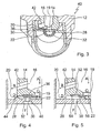
- FIG. 3 a gas valve 40 is shown, which is essentially after that FIG. 1 equivalent.
- the gas valve 40 differs from the gas valve FIG. 1 However, by the formation of the valve closing member 14, in that it is not provided with radially aligned Abströmbohrept, but adjacent to the axial outflow bore 19 at an angle relative to the longitudinal axis of the valve closure member 14 aligned Abströmbohrept 42 which lead to the outer pressure region 20, what a Optimized flow behavior of the gas in question causes.
- the sealing area of the gas valve 40 is in FIG. 4 shown in detail. It is characterized in that the nozzle plate 28 has an optionally annular base 44 which serves as a stop for the valve closing member 14 and is arranged in the edge region of the latter.
- the nozzle plate 28 serving on the nozzle 30 each serving as a sealing lip skirts 46 which engage in the closed valve closure member 14 in the annular elastomeric seal 36 which is embedded in an annular groove of the valve closure member.
- the edges of the elastomeric seal 36 are chamfered and the inflow edges of the nozzles 30 rounded with a radius of curvature of about 0.05 mm.
- the flow of the gas in question in the gas valve 40 is also FIG. 4 refer to.
- the gas flows from the inflow side according to an arrow A through the first axial bore 16 of the valve closing member 14 and from there through the outflow channels 42 according to an arrow B in the outer pressure region 20 and on the other according to an arrow C through the second axial bore 19, the Part of the inner pressure region 22 is.
- opening the valve closing member 14 gas flows from the outer pressure region 20 according to an arrow D and from the inner pressure region 22 according to an arrow E to the nozzle 30 and via this according to an arrow F to the downstream side of the gas valve 40th
- FIG. 5 is an alternative embodiment of a sealing region in a gas valve of the FIG. 3 shown type shown.
- the sealing area after FIG. 5 differs from the one after FIG. 4 in that it comprises a sealing ring 52 which is provided with two sealing lips 54 and 56 which are arranged on the inner or on the outer edge of the sealing ring 52.
- the sealing lips 54 and 56 engage with the valve closing member 14 is closed to the sealing plate 28, which is formed here without stop base and without aprons.
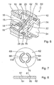
- FIGS. 6 to 8 a further embodiment of a gas valve 60 is shown, which largely according to the gas valve FIG. 1 corresponds to this but differs in that it is not with a nozzle plate but with a trained as a so-called kidney plate sealing plate or sealing seat disc 62 equipped in the FIGS. 7 and 8 is shown in detail.
- the kidney plate 62 serves as a sealing seat for the valve closing member 14 and for the sealing ring embedded therein and in the present case has two kidney-shaped or lenticular apertures or channels 64 and 66, which are arranged along a circular line, the diameter of which substantially mean diameter of the annular end surface 24 of the valve closing member 14 corresponds.
- the openings 64 and 66 are separated from one another by two webs 68 and 70 and open into a central bore 72 which represents a dead volume space and which is formed on a component 74 of the gas valve 60 having the outflow side 34 and which leads to a downstream throttle bore or nozzle 76. by means of which the pressure prevailing at the outflow side 34 is defined. It is also conceivable to provide more than two, for example three or four kidney-shaped openings or channels in the kidney disk 62.
- FIG. 8 it can be seen, have the apertures 64 and 66 rounded inflow edges 67, which are arranged on the facing in the direction of the valve closing member 14 side of the kidney plate 62 and have a radius of curvature of about 0.05 mm.
- valve closing member gas flows from the inner pressure region 22 and the outer pressure region 20 uniformly over the flow area at the sealing seat and the pressure surface provided by the openings 64 and 66 in the dead volume space 62 a. From there, the gas flows via the throttle bore 76 at sonic or supersonic speed to the downstream side 34.
- any compression shocks occurring in the gas valve 60 are displaced to the outflow side 34 forming a damping space and therefore do not occur on the kidney plate 62.
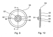
- FIG. 13 is an alternate embodiment of a kidney plate 90 for use with a gas valve of FIG FIG. 6 shown type shown.
- the kidney plate 90 differs from the one in the FIGS. 7 and 8 kidney plate shown in that it has a paragraph or base 91 which projects into the Totvolumenraum 72 and is conical, so that the time required to fill the Totvolumenraums 72 can be shortened.
- the paragraph 91 is used to avoid flow vortices, which can occur when opening the valve closure member, in particular for small valve strokes, by detachment of the gas flow.
- the in FIG. 6 Gas valve may also be provided with a valve closing member, which corresponds to that of the in FIG. 3 Corresponds to the gas valve shown and is therefore provided with outflow holes whose axes are not aligned radially with respect to the longitudinal axis of the valve closure member but include an acute angle with the latter.
- a valve closing member which corresponds to that of the in FIG. 3 Corresponds to the gas valve shown and is therefore provided with outflow holes whose axes are not aligned radially with respect to the longitudinal axis of the valve closure member but include an acute angle with the latter.
- FIG. 6 illustrated gas valve with a sealing area of in FIG. 4 or 5 be provided type shown. It may therefore have a serving as a stop base, which is formed on the sealing seat plate or kidney plate or on the valve closure member and / or is provided with a sealing ring of an elastomeric material, which may be provided with sealing lips or may be formed plan.
- the edges 67 are preferably bevelled or rounded to
Landscapes
- Engineering & Computer Science (AREA)
- General Engineering & Computer Science (AREA)
- Mechanical Engineering (AREA)
- Lift Valve (AREA)
- Magnetically Actuated Valves (AREA)
- Check Valves (AREA)
Abstract
Description
Die Erfindung geht von einem Gasventil, insbesondere von einem Gasventil mit elektromagnetischer Betätigung, gemäß der im Oberbegriff des Patentanspruches 1 näher definierten Art aus.The invention is based on a gas valve, in particular of a gas valve with electromagnetic actuation, according to the closer defined in the preamble of claim 1. Art.
Ein derartiges Gasventil ist aus der Praxis bekannt und beispielsweise als Gassteuerventil bei einer Brennstoffzelle einsetzbar.Such a gas valve is known from practice and can be used for example as a gas control valve in a fuel cell.
Das bekannte Gasventil umfaßt ein Ventilgehäuse, in dem ein Ventilschließglied axial verschieblich geführt ist, das mit einer elektromagnetischen Betätigungseinheit verbunden ist. Das Ventilschließglied dient zur Steuerung eines Gasstroms von einer Zuströmseite zu einer Abströmseite und wirkt hierzu mit einem Ventilsitz zusammen, der an einer Ventilplatte ausgebildet ist. Die Zuströmseite ist mit einem das Ventilschließglied umgebenden Druckbereich verbunden. Beim Öffnen des Ventilschließglieds erfolgt ein Gasstrom von dem Druckbereich zu einer Bohrung der Ventilplatte, welche in eine Düse mündet, die zu der Abströmseite führt.The known gas valve comprises a valve housing in which a valve closing member is guided axially displaceable, which is connected to an electromagnetic actuator unit. The valve closing member serves to control a gas flow from an inlet side to an outlet side and cooperates for this purpose with a valve seat which is formed on a valve plate. The inflow side is connected to a pressure region surrounding the valve closure member. When opening the valve closing member, a gas flow from the pressure area to a bore of the valve plate, which opens into a nozzle which leads to the downstream side.
An der Stirnseite des Ventilschließglieds ist üblicherweise ein Dichtbund ausgebildet, der bei geschlossenem Ventilschließglied auf eine Dichtplatte aufsetzt und eine zylindrische Bohrung der Dichtplatte umgibt. Bei geschlossenem Ventilschließglied herrscht zwischen dem das Ventilschließglied umgebenden Druckbereich und dem an die Stirnseite des Ventilschließglieds grenzenden Ventilraum eine große Druckdifferenz, so daß die zum Öffnen des Ventilschließglieds erforderliche Magnetkraft groß ausgelegt sein muß.On the front side of the valve closure member, a sealing collar is usually formed, which rests on a sealing plate with a closed valve closing member and surrounds a cylindrical bore of the sealing plate. When the valve closing member is closed, there is a large pressure difference between the pressure region surrounding the valve closure member and the valve space adjoining the end face of the valve closure member, so that the magnetic force required to open the valve closure member must be large.
Des weiteren haben Gase, wie Wasserstoff oder Methan, im Vergleich zu flüssigen Kraftstoffen eine geringere Dichte. Daher ist bei Gasen häufig ein wesentlich gößerer Volumenstrom erforderlich, so daß bei einem Gaseventil eine große Durchstromfläche am Ventildichtsitz wünschenswert ist. Hierbei ist zu beachten, daß der Ventilhub wegen der hohen Dynamik des Ventils begrenzt ist, was zur Folge hat, daß der Dichtsitz im wesentlichen hinsichtlich seines Durchmessers veränderbar ist. Eine Vergrößerung des Dichtsitzes führt aber zu einer Erhöhung der aufzubringenden Öffnungskraft bzw. Magnetkraft, was wiederum einen erhöhten Stromverbrauch zur Folge hat. Ferner kann der Durchmesser des Dichtsitzes aufgrund eines häufig beschränkten Bauraums nicht beliebig groß gewählt werden. Die Volumenströme bzw. Massenströme des strömenden Gases sind aus diesen Gründen häufig nicht hinreichend groß für die bei Gasmotoren und Brennstoffzellenantrieben herrschenden Anforderungen.Furthermore, gases such as hydrogen or methane have lower density compared to liquid fuels. Therefore, in gases often a much larger volume flow is required, so that in a gas valve, a large flow area is desirable at the valve seat. It should be noted that the valve lift is limited because of the high dynamics of the valve, with the result that the sealing seat is variable in terms of its diameter substantially. An enlargement of the sealing seat but leads to an increase in the applied opening force or magnetic force, which in turn has an increased power consumption. Furthermore, the diameter of the sealing seat can not be chosen arbitrarily large due to a frequently limited installation space. For these reasons, the volume flows or mass flows of the flowing gas are often not sufficiently large for the requirements prevailing in gas engines and fuel cell drives.
Das Gasventil nach der Erfindung mit den Merkmalen nach dem Oberbegriff des Patentanspruches 1, bei dem die Zuströmseite stromab mit einem inneren und einem äußeren Druckbereich verbunden ist, welche Druckbereiche stromauf des Ventilsitzes angeordnet sind, wobei der innere Druckbereich einen axialen Druckkanal des Ventilschließglieds umfaßt, der an der freien Stirnseite des Ventilschließglieds axial austritt, und der äußere Druckbereich das Ventilschließglied umgibt, hat den Vorteil, daß das Ventilschließglied mit geringem Kraftaufwand betätigbar ist, da bei dessen Öffnen in dem inneren und in dem äußeren Druckbereich im wesentlichen der gleiche Druck herrscht und aus beiden Druckbereichen Gas in Richtung der Durchströmöffnung strömt. Dies hat gegenüber einem Gasventil nach dem Stand der Technik den Vorteil, daß eine insbesondere elektromagnetische Betätigungseinheit für das Ventilschließglied mit geringerer Leistung auslegbar ist.The gas valve according to the invention having the features according to the preamble of claim 1, wherein the upstream side is connected to an inner and an outer pressure region, which pressure regions are arranged upstream of the valve seat, wherein the inner pressure region comprises an axial pressure channel of the valve closure member, the axially exits at the free end face of the valve closure member, and the outer pressure region surrounds the valve closure member, has the advantage that the valve closure member is actuated with little effort, as in its opening in the inner and in the outer pressure region substantially the same pressure prevails and off gas flows in the direction of the throughflow opening at both pressure ranges. This has the advantage over a gas valve according to the prior art that a particular electromagnetic actuator unit for the valve closure member with lower power is interpretable.
Ein Ventil gemäß dem Stand der Technik ist aus dem Dokument
Bei dem Gasventil nach der Erfindung handelt es sich um ein Ventil, das nach dem Druckausgleichsprinzip arbeitet, hohe Massenströme zuläßt sowie nur geringe Kräfte zur Betätigung des Ventilschließglieds erfordert.The gas valve according to the invention is a valve which operates according to the pressure compensation principle, allows high mass flows and requires only small forces to actuate the valve closure member.
Das Gasventil nach der Erfindung ist insbesondere zur Massenstromregelung von Gasen wie Wasserstoff und Erdgas geeignet und kann beispielsweise bei einer Brennstoffzelle eingesetzt werden.The gas valve according to the invention is particularly suitable for mass flow control of gases such as hydrogen and natural gas and can be used for example in a fuel cell.
Das Gasventil nach der Erfindung ist zweckmäßig derart ausgelegt, daß das Ventilschließglied stirnseitig eine als Ringfläche ausgebildete Dichtfläche aufweist. Die Dichtfläche überdeckt bei geschlossenem Ventilschließglied die mindestens eine Durchströmöffnung.The gas valve according to the invention is expediently designed such that the valve closure member has an end face designed as an annular surface sealing surface. When the valve closing member is closed, the sealing surface covers the at least one throughflow opening.
Bei einem Gasventil gemäß der Erfindung ist der innere Druckbereich über mindestens einen in dem Ventilschließglied ausgebildeten Abströmkanal mit dem äußeren Druckbereich verbunden. Der Abströmkanal ist als radial ausgerichtete Bohrung des Ventilschließglieds ausgebildet, kann aber auch mit einem bestimmten Anstellwinkel in Strömungsrichtung gegenüber einer Achse des Ventilschließglieds geneigt sein und von einer als Zufuhrkanal dienenden axialen Bohrung an die Außenseite des Ventilschließglieds führen. Der Zufuhrkanal mündet dann auch in eine axiale Bohrung gegebenenfalls verminderten Durchmessers, die den inneren Druckbereich darstellt bzw. ein Teil dessen ist. Insbesondere bei dieser Ausführungsform ist zuverlässig gewährleistet, daß ein Druckausgleich zwischen dem inneren Druckbereich und dem äußeren Druckbereich erfolgt und somit die auf das Ventilschließglied wirkenden Fluidkräfte ausgeglichen sind.In a gas valve according to the invention, the inner pressure region is connected to the outer pressure region via at least one outflow channel formed in the valve closure member. The outflow channel is formed as a radially aligned bore of the valve closure member, but may also be inclined with a certain angle of attack in the flow direction relative to an axis of the valve closure member and lead from serving as a supply channel axial bore to the outside of the valve closure member. The supply channel then also opens into an axial bore of possibly reduced diameter, which represents the inner pressure region or is a part thereof. In particular, in this embodiment, it is reliably ensured that a pressure equalization takes place between the inner pressure region and the outer pressure region and thus the fluid forces acting on the valve closure member are compensated.
Um einen möglichst homogenen Gasfluß zwischen den beiden Druckbereichen und der Abströmseite zu gewährleisten, hat die Ventilplatte mindestens zwei Durchströmöffnungen, die mittels der Dichtfläche abdeckbar sind. Beispielsweise kann die Ventilplatte auch vier Durchströmbohrungen aufweisen. Bei einer ringfömig ausgebildeten Dichtfläche sind die Durchströmöffnungen entlang einer Kreislinie angeordnet, deren Radius etwa dem mittleren Radius der Dichtfläche entspricht.In order to ensure the most homogeneous possible gas flow between the two pressure areas and the downstream side, the valve plate has at least two flow openings, which can be covered by means of the sealing surface are. For example, the valve plate may also have four flow holes. In a ringfömig formed sealing surface, the flow openings are arranged along a circular line whose radius corresponds approximately to the mean radius of the sealing surface.
Die Durchströmöffnungen können als nierenförmige bzw. linsenförmige Durchbrüche oder auch als entlang der Kreislinie angeordnete Düsen ausgebildet sein. Im ersteren Fall ist es in der Regel üblich, stromab der Durchbrüche bzw. Kanäle und stromauf der Abströmseite eine beispielsweise an der Dichtplatte ausgebildete Drosselbohrung bzw. Düse anzuordnen, deren Dimensionen die zu der Abströmseite strömende Gasmenge festlegen. Wenn in dem inneren und dem äußeren Druckbereich beispielsweise ein Druck von etwa 8 bar herrscht, wirkt dieser Druck beim Öffnen des Ventilschließglieds durch die linsenförmigen Durchbrüche bis zu der Drosselbohrung. Mittels der Drosselbohrung wird der Druck auf beispielsweise 1 bar reduziert.The flow-through openings can be designed as kidney-shaped or lenticular openings or as nozzles arranged along the circumference. In the former case, it is usually customary to arrange a throttle bore or nozzle formed, for example, on the sealing plate downstream of the apertures or channels and upstream of the downstream side, whose dimensions determine the gas quantity flowing to the downstream side. If, for example, a pressure of about 8 bar prevails in the inner and the outer pressure region, this pressure acts on opening of the valve closing member through the lenticular apertures up to the throttle bore. By means of the throttle bore, the pressure is reduced to, for example, 1 bar.
Bei Ausbildung der Durchströmöffnungen als nierenförmige bzw. linsenförmige Durchbrüche ist stromab derselben üblicherweise eine einen Totvolumenraum darstellende Zentralbohrung des Gasventils angeordnet, von wo aus das betreffende Gas über die Drosselbohrung mit Schall- bzw. Überschallgeschwindigkeit zu der Abströmseite strömt. Letztere kann einen Dämpfungsraum bilden oder auch an die Atmosphäre führen.When forming the through-flow openings as kidney-shaped or lenticular apertures, a central bore of the gas valve which represents a dead volume space is usually arranged downstream from where the gas in question flows via the throttle bore at sonic or supersonic velocity to the downstream side. The latter can form a damping chamber or lead to the atmosphere.
Die Querfläche der stromab des Totvolumenraums angeordneten Drosselbohrung ist zur Vermeidung eines Einflusses von Druckstößen auf den Dichtsitz bevorzugt um den Faktor 2,0 bis 2,5 kleiner als die Fläche der als nierenförmige bzw. linsenförmige Durchbrüche ausgebildeten Durchströmöffnungen.The transverse surface of the throttle bore arranged downstream of the dead volume space is preferably smaller by a factor of 2.0 to 2.5 than the area of the flow-through openings designed as kidney-shaped or lenticular breaches in order to avoid an influence of pressure surges on the sealing seat.
Zur Verbesserung der Dynamik des Gasventils nach der Erfindung kann die zur Befüllung des Totvolumenraums erforderliche Zeit dadurch verringert werden, daß an der Dichtplatte ein vorzugsweise konisch ausgebildeter Absatz bzw. Sockel angeordnet ist, der in den Totvolumenraum ragt. Der Absatz mindert des weiteren die Ausbildung von Strömungswirbeln, die beim Öffnen des Ventilschließglieds, insbesondere bei kleinen Ventilhüben, durch Ablösung der Gasströmung entstehen können.To improve the dynamics of the gas valve according to the invention, the time required for filling the dead volume space can be reduced by arranging on the sealing plate a preferably conically shaped shoulder or pedestal which protrudes into the dead volume space. The paragraph further reduces the formation of flow vortices, which can occur when opening the valve closure member, especially in small valve strokes, by detachment of the gas flow.
Bei Ausbildung der Durchströmöffnungen als Düsen kann auf die Nachschaltung einer Drosselbohrung verzichtet werden, da durch entsprechende Auslegung der Düsen der an der Abströmseite wirkende Gasdruck einstellbar ist.When forming the flow openings as nozzles can be dispensed with the downstream of a throttle bore, since by appropriate design of the nozzle acting on the downstream gas pressure is adjustable.
Die Dichtplatte kann aus unterschiedlichen Materialien, wie beispielsweise Stahl, PEEK mit Kohlefasern, einem Hartkunststoff oder einer Keramik, hergestellt sein, und zwar beispielsweise nach einem Ätz-, einem Erodier- oder einem Laserverfahren.The sealing plate may be made of different materials, such as steel, PEEK with carbon fibers, a hard plastic or a ceramic, for example after an etching, an erosion or a laser process.
Das Gasventil nach der Erfindung kann zur Dichtigkeitserhöhung am Ventilsitz eine Elastomerdichtung umfassen. Diese ist zweckmäßig an der an der Stirnseite des Ventilschließglieds liegenden Dichtfläche angeordnet und kann eine oder auch mehrere Dichtlippen aufweisen.The gas valve according to the invention may comprise an elastomeric seal for increasing the seal on the valve seat. This is expediently arranged on the sealing surface lying on the end face of the valve closing member and may have one or more sealing lips.
Zweckmäßig ist die Elastomerdichtung ringförmig ausgebildet und an dem Ventilschließglied an dessen Stirnseite in eine korrespondierende Ringnut eingebettet. Sie kann mit zwei Dichtlippen versehen sein, von denen eine am inneren Rand des Dichtrings angeordnet und damit dem inneren Druckbereich zugeordnet und die andere am äußeren Rand des Dichtrings angeordnet und damit dem äußeren Druckbereich zugeordnet ist.Suitably, the elastomeric seal is annular and embedded in the valve closure member at the end face in a corresponding annular groove. It can be provided with two sealing lips, one of which is arranged on the inner edge of the sealing ring and thus associated with the inner pressure region and the other arranged on the outer edge of the sealing ring and thus associated with the outer pressure range.
Des weiteren kann das Gasventil nach der Erfindung einen als Anschlag für das Ventilschließglied dienenden Sockel aufweisen. Dieser ist beispielsweise an der Ventilplatte ausgebildet. Der Anschlag stellt einen Prallabfänger dar und begrenzt die Verformung des elastomeren Dichtrings und damit dessen Verschleiß und definiert den Luftspalt an einem zur Betätigung des Ventilschließglieds dienenden Magnetanker eindeutig. Bei einem in einer Nut eingebetteten Dichtring mit Dichtlippen ist es denkbar, daß das Ventilschließglied selbst einen Schutzring bzw. Prallabfänger zur Schonung des Dichtrings bildet.Furthermore, the gas valve according to the invention may have a base serving as a stop for the valve closure member. This is formed for example on the valve plate. The stopper is a baffle trap and limits the deformation of the elastomeric sealing ring and thus its wear and defines the air gap on a serving for actuation of the valve closure member armature clearly. When embedded in a groove sealing ring with sealing lips, it is conceivable that the valve closure member itself forms a protective ring or baffle catcher to protect the sealing ring.
Um in der Schließstellung des Ventilschließglieds eine hohe Dichtigkeit zu gewährleisten, können an der Dichtplatte auch Schürzen zur Auflage der Elastomerdichtung ausgebildet sein. Diese Schürzen bilden beispielsweise die Ränder der Düsen.In order to ensure a high density in the closed position of the valve closure member, aprons for supporting the elastomeric seal may be formed on the sealing plate. These skirts, for example, form the edges of the nozzles.
Weitere Vorteile und vorteilhafte Ausgestaltungen des Gegenstandes nach der Erfindung sind der Beschreibung, der Zeichnung und den Patentansprüchen entnehmbar.Further advantages and advantageous embodiments of the article according to the invention are the description, the drawings and the claims removed.
Zeichnungdrawing
Fünf Ausführungsbeispiele eines Gasventils nach der Erfindung sind in der Zeichnung schematisch vereinfacht dargestellt und werden in der nachfolgenden Beschreibung näher erläutert. Es zeigen
-
Figur 1 einen Längsschnitt durch ein Gasventil nach der Erfindung mit einer Düsenplatte; -
Figur 2 eine Aufsicht auf die Düsenplatte des Gasventils nachFigur 1 ; -
Figur 3 eine zweite Ausführungsform eines Gasventils nach der Erfindung mit einer Düsenplatte; -
Figur 4 einen Schnitt durch einen Dichtbereich des Gasventils nachFigur 3 in vergrößerter Darstellung; -
Figur 5 eineFigur 4 entsprechende Ansicht, jedoch mit einem veränderten Dichtbereich; -
Figur 6 einen Schnitt durch ein Gasventil nach der Erfindung mit einer sogenannten Nierenplatte; -
Figur 7 eine Aufsicht auf die Nierenplatte des Gasventils nachFigur 6 ; -
Figur 8 einen Schnitt durch die Nierenplatte nachFigur 7 entlang der Linie VIII-VIII inFigur 7 ; -
Figur 9 eine Aufsicht auf eine alternative Ausführungsform einer Nierenplatte; und -
Figur 10Figur 9 entlang der Linie X-X inFigur 9 .
-
FIG. 1 a longitudinal section through a gas valve according to the invention with a nozzle plate; -
FIG. 2 a top view of the nozzle plate of the gas valve afterFIG. 1 ; -
FIG. 3 a second embodiment of a gas valve according to the invention with a nozzle plate; -
FIG. 4 a section through a sealing region of the gas valve afterFIG. 3 in an enlarged view; -
FIG. 5 aFIG. 4 corresponding view, but with a changed sealing area; -
FIG. 6 a section through a gas valve according to the invention with a so-called kidney plate; -
FIG. 7 a top view of the kidney plate of the gas valveFIG. 6 ; -
FIG. 8 a section through the kidney plate afterFIG. 7 along the line VIII-VIII inFIG. 7 ; -
FIG. 9 a plan view of an alternative embodiment of a kidney plate; and -
FIG. 10 a section through the kidney plate afterFIG. 9 along the line XX inFIG. 9 ,
In
Das Gasventil 10 umfaßt ein Gehäuse 12, in welchem ein Ventilschließglied 14 in einer langen, von dem Gehäuse 12 gebildeten Führung axial verschieblich geführt ist, das mit einer hier nicht näher dargestellten elektromagnetischen Betätigungseinheit in Wirkverbindung steht und mit einem Gleitlack beschichet ist.The
Das Ventilschließglied 14 umfaßt eine als Zufuhrkanal dienende, erste Axialbohrung 16, die mit einer hier nicht dargestellten Zuströmseite des Gasventils 10 verbunden ist. Von der ersten Axialbohrung 16 zweigen vier über den Umfang des Ventilschließglieds 14 verteilte Radialbohrungen 18 ab, die jeweils eine radiale Abströmbohrung bilden und von denen in
Beim Betrieb des Gasventils 10 strömt Gas aus der ersten Axialbohrung 16 über die radialen Abströmbohrungen 18 in den einen Gasraum darstellenden, äußeren Druckbereich 20 und über die axiale Abströmbohrung 19 an die freie Stirnseite 24 des Ventilschließglieds 14.During operation of the
Sowohl der innere Druckbereich 22 als auch der äußere Druckbereich 20 sind stromauf eines Ventilsitzes 26 angeordnet, der mit der freien Stirnseite 24 des Ventilschließglieds 14 zusammenwirkt und an einer als Dichtplatte bzw. Dichtsitzscheibe dienenden Düsenplatte 28 ausgebildet ist, die mit dem Ventilschließglied 14 zusammenwirkt.Both the
In der Düsenplatte 28 sind, wie
Die Stirnseite 24 des Ventilschließglieds 14 ist als Ringfläche ausgebildet, an der eine aus einem elastomeren Werkstoff gefertigte Ringdichtung 36 eingebettet ist. Die Ringdichtung 36 schließt in Schließstellung des Ventilschließglieds 14 die Düsen 32 ab, so daß ein Gasstrom von den Druckbereichen 20 und 22 zu der Abströmseite gesperrt ist.The end face 24 of the
In
Der Dichtbereich des Gasventils 40 ist in
Des weiteren weist die Düsenplatte 28 an den Düsen 30 jeweils als Dichtlippe dienende Schürzen 46 auf, die bei geschlossenem Ventilschließglied 14 in die ringförmige Elastomerdichtung 36 eingreifen, die in eine Ringnut des Ventilschließglieds eingebettet ist. Zur Optimierung der Strömungsbedingungen sind die Kanten der Elastomerdichtung 36 angeschrägt und die Einströmkanten der Düsen 30 mit einem Krümmungsradius von etwa 0,05 mm abgerundet.Furthermore, the
Die Strömung des betreffenden Gases in dem Gasventil 40 ist ebenfalls
In
In den
Die Nierenplatte 62 dient als Dichtsitz für das Ventilschließglied 14 bzw. für den in dieses eingebetteten Dichtring und weist im vorliegenden Fall zwei nieren- bzw. linsenförmige Durchbrüche bzw. Kanäle 64 und 66 auf, die entlang einer Kreislinie angeordnet sind, deren Durchmesser im wesentlichen dem mittleren Durchmesser der ringförmigen Stirnfläche 24 des Ventilschließglieds 14 entspricht. Die Durchbrüche 64 und 66 sind durch zwei Stege 68 und 70 voneinander getrennt und münden in eine einen Totvolumenraum darstellende Zentralbohrung 72, die an einem die Abströmseite 34 aufweisenden Bauteil 74 des Gasventils 60 ausgebildet ist und die zu einer nachgeschalteten Drosselbohrung bzw. Düse 76 führt, mittels der der an der Abströmseite 34 herrschende Druck definiert ist. Denkbar ist es auch, mehr als zwei, beispielsweise drei oder vier nierenförmige Durchbrüche bzw. Kanäle in der Nierenscheibe 62 vorzusehen.The
Wie
Bei Betätigung des Ventilschließglieds strömt Gas aus dem inneren Druckbereich 22 und dem äußeren Druckbereich 20 gleichmäßig über die Durchströmfläche am Dichtsitz und die mittels der Durchbrüche 64 und 66 bereitgestellte Druckfläche in den Totvolumenraum 62 ein. Von dort strömt das Gas über die Drosselbohrung 76 mit Schall- bzw. Überschallgeschwindigkeit an die Abströmseite 34 ab.Upon actuation of the valve closing member gas flows from the
Etwaig in dem Gasventil 60 auftretende Verdichtungsstöße sind an die einen Dämpfungsraum bildende Abströmseite 34 verlagert und treten mithin nicht an der Nierenplatte 62 auf. Dies kann dadurch erreicht werden, daß die Durchströmfläche am Dichtsitz bzw. die Fläche der nierenförmigen Durchbrüche 64 und 66 so gewählt ist, daß sie bei einem maximalen Hub des Ventilschließglieds 14 um mindestens den Faktor 2 bis 2,5 größer ist als die Drosselfläche der Düse 76.Any compression shocks occurring in the
In den
Des weiteren weist die Nierenplatte 90 an der dem Ventilschließglied 14 zugewandten Seite eine ringförmige Vertiefung 92 sowie eine zentral angeordnete, kreisförmige Vertiefung 93 auf, wobei die ringförmige Vertiefung 92 dem äußeren Druckbereich 20 und die kreisförmige Vertiefung 93 dem inneren Druckbereich 22 zugeordnet ist. Zwischen der ringförmigen Vertiefung 92 und der kreisförmigen Vertiefung 93 ist mithin ein Podest 94 ausgebildet, das die Durchbrüche bzw. Kanäle 64 und 66 umgibt.Furthermore, the
Die Erfindung ist nicht auf die oben beschriebenen Ausführungsbeispiele beschränkt. Vielmehr kann beispielsweise das in
Claims (13)
- Gas valve, in particular with electromagnetic actuation, comprising a valve closing member (14) which controls a gas stream from an inflow side to an outflow side (34) and interacts with a valve seat (26) which is formed on a valve plate (28, 62, 90) with at least one throughflow opening (30; 64, 66) which leads to the outflow side (34), the inflow side being connected downstream to an inner (22) and an outer (20) pressure region, which pressure regions (20, 22) are arranged upstream of the valve seat (26), the inner pressure region (22) comprising an axial pressure channel (19) of the valve closing member (14) which axial pressure channel (19) exits axially on the free end side (24) of the valve closing member (14), and the outer pressure region (20) surrounding the valve closing member (14), characterized in that the valve closing member (14) comprises a first axial hole (16) which serves as inlet channel and from which at least one radial hole (18) branches off perpendicularly or at least at an angle with respect to the longitudinal axis of the valve closing member (14) as outflow hole (42) to the outer pressure region (20), and the first axial hole (16) opens in the axial direction into a second axial hole (19) which represents the axial pressure channel (19) to the inner pressure region (22).
- Gas valve according to Claim 1, characterized in that, on the end side, the valve closing member (14) has a sealing face which is configured as an annular face.
- Gas valve according to Claim 1 or 2, characterized in that the inner pressure region (22) is connected to the outer pressure region (20) via at least one outflow channel (18) which is formed in the valve closing member (14).
- Gas valve according to one of Claims 1 to 3, characterized in that the valve plate (28, 62, 90) has at least two throughflow openings (30; 64, 66) which can be covered by means of the sealing face.
- Gas valve according to Claim 4, characterized in that the throughflow openings (64, 66) are of kidney-shaped or lenticular configuration and lead to a dead volume space (72).
- Gas valve according to Claim 4 or 5, characterized in that a restrictor bore (76) is arranged downstream of the throughflow openings (64, 66) and upstream of the outflow side (34).
- Gas valve according to Claim 5 or 6, characterized in that a preferably conical shoulder (91) which protrudes into the dead volume space (72) is formed on the valve plate (90).
- Gas valve according to Claim 4, characterized in that the throughflow openings (30) are formed as nozzles along a circular line.
- Gas valve according to one of Claims 1 to 8, characterized in that an elastomer seal (36, 52) is arranged on the sealing face of the valve closing member (14).
- Gas valve according to Claim 9, characterized in that the elastomer seal (52) has at least one sealing lip (54, 56).
- Gas valve according to one of Claims 1 to 10, characterized by a base (44) which serves as stop for the valve closing body (14).
- Gas valve according to one of Claims 1 to 11, characterized in that aprons (46) for engagement into the elastomer seal (36) are formed on the sealing plate (28).
- Gas valve according to one of Claims 1 to 12, characterized in that the second axial hole (19) in the valve closing member (14) has a smaller diameter than the diameter of the first axial hole (16).
Applications Claiming Priority (3)
| Application Number | Priority Date | Filing Date | Title |
|---|---|---|---|
| DE10249964 | 2002-10-26 | ||
| DE2002149964 DE10249964A1 (en) | 2002-10-26 | 2002-10-26 | gas valve |
| PCT/DE2003/003386 WO2004040176A2 (en) | 2002-10-26 | 2003-10-13 | Gas valve |
Publications (3)
| Publication Number | Publication Date |
|---|---|
| EP1558865A2 EP1558865A2 (en) | 2005-08-03 |
| EP1558865B1 EP1558865B1 (en) | 2008-05-07 |
| EP1558865B2 true EP1558865B2 (en) | 2011-12-28 |
Family
ID=32087218
Family Applications (1)
| Application Number | Title | Priority Date | Filing Date |
|---|---|---|---|
| EP03776795A Expired - Lifetime EP1558865B2 (en) | 2002-10-26 | 2003-10-13 | Gas valve |
Country Status (3)
| Country | Link |
|---|---|
| EP (1) | EP1558865B2 (en) |
| DE (2) | DE10249964A1 (en) |
| WO (1) | WO2004040176A2 (en) |
Families Citing this family (2)
| Publication number | Priority date | Publication date | Assignee | Title |
|---|---|---|---|---|
| DE102005059159B4 (en) * | 2005-12-12 | 2008-05-29 | Daimler Ag | Damper device of a Eduktversorgungssystems in a fuel cell system and delivery system |
| US10364758B2 (en) | 2016-12-20 | 2019-07-30 | Continental Powertrain, USA, LLC | High pressure gas phase injector |
Citations (11)
| Publication number | Priority date | Publication date | Assignee | Title |
|---|---|---|---|---|
| US2325878A (en) † | 1939-10-28 | 1943-08-03 | William A Ray | Fluid control valve |
| DE1111454B (en) † | 1957-05-10 | 1961-07-20 | Bendix Corp | Fuel injector |
| US4515347A (en) † | 1982-12-27 | 1985-05-07 | Joy Manufacturing Company | Valve seat structure |
| GB2188982A (en) † | 1986-04-14 | 1987-10-14 | Colt Ind Inc | Multi-point i.c. engine fuel injection apparatus |
| DE3716402A1 (en) † | 1986-05-16 | 1987-11-19 | Lucas Ind Plc | FUEL INJECTION NOZZLE |
| US4883252A (en) † | 1989-01-23 | 1989-11-28 | Colt Industries Inc. | Electromagnet and valve assembly |
| US5348233A (en) † | 1993-03-01 | 1994-09-20 | General Motors Corporation | High volume gaseous fuel injector |
| DE4444782A1 (en) † | 1994-12-15 | 1996-06-20 | Herion Werke Kg | Diaphragm valve for aggressive media |
| DE19731557A1 (en) † | 1997-07-23 | 1999-01-28 | Mann & Hummel Filter | Valve |
| DE19905722A1 (en) † | 1998-02-24 | 1999-08-26 | Hoerbiger Ventilwerke Gmbh | Adjustable electromagnetic gas valve for gas fueled internal combustion engine |
| EP1244116A2 (en) † | 2001-03-20 | 2002-09-25 | WABCO GmbH & CO. OHG | Method of manufacturing an armature |
Family Cites Families (4)
| Publication number | Priority date | Publication date | Assignee | Title |
|---|---|---|---|---|
| FR990166A (en) * | 1946-11-08 | 1951-09-18 | Automatic valve | |
| DE8403943U1 (en) * | 1984-02-10 | 1984-05-03 | Roser, Erich, 7777 Salem | DISC CHECK VALVE |
| DE10063710A1 (en) * | 2000-12-20 | 2002-07-04 | Wabco Gmbh & Co Ohg | valve means |
| DE10108492A1 (en) * | 2001-02-22 | 2002-09-05 | Mueller Co Ax Gmbh | coaxial valve |
-
2002
- 2002-10-26 DE DE2002149964 patent/DE10249964A1/en not_active Withdrawn
-
2003
- 2003-10-13 DE DE50309808T patent/DE50309808D1/en not_active Expired - Lifetime
- 2003-10-13 EP EP03776795A patent/EP1558865B2/en not_active Expired - Lifetime
- 2003-10-13 WO PCT/DE2003/003386 patent/WO2004040176A2/en not_active Ceased
Patent Citations (11)
| Publication number | Priority date | Publication date | Assignee | Title |
|---|---|---|---|---|
| US2325878A (en) † | 1939-10-28 | 1943-08-03 | William A Ray | Fluid control valve |
| DE1111454B (en) † | 1957-05-10 | 1961-07-20 | Bendix Corp | Fuel injector |
| US4515347A (en) † | 1982-12-27 | 1985-05-07 | Joy Manufacturing Company | Valve seat structure |
| GB2188982A (en) † | 1986-04-14 | 1987-10-14 | Colt Ind Inc | Multi-point i.c. engine fuel injection apparatus |
| DE3716402A1 (en) † | 1986-05-16 | 1987-11-19 | Lucas Ind Plc | FUEL INJECTION NOZZLE |
| US4883252A (en) † | 1989-01-23 | 1989-11-28 | Colt Industries Inc. | Electromagnet and valve assembly |
| US5348233A (en) † | 1993-03-01 | 1994-09-20 | General Motors Corporation | High volume gaseous fuel injector |
| DE4444782A1 (en) † | 1994-12-15 | 1996-06-20 | Herion Werke Kg | Diaphragm valve for aggressive media |
| DE19731557A1 (en) † | 1997-07-23 | 1999-01-28 | Mann & Hummel Filter | Valve |
| DE19905722A1 (en) † | 1998-02-24 | 1999-08-26 | Hoerbiger Ventilwerke Gmbh | Adjustable electromagnetic gas valve for gas fueled internal combustion engine |
| EP1244116A2 (en) † | 2001-03-20 | 2002-09-25 | WABCO GmbH & CO. OHG | Method of manufacturing an armature |
Also Published As
| Publication number | Publication date |
|---|---|
| EP1558865A2 (en) | 2005-08-03 |
| DE50309808D1 (en) | 2008-06-19 |
| EP1558865B1 (en) | 2008-05-07 |
| DE10249964A1 (en) | 2004-05-06 |
| WO2004040176A3 (en) | 2004-09-10 |
| WO2004040176A2 (en) | 2004-05-13 |
Similar Documents
| Publication | Publication Date | Title |
|---|---|---|
| EP1801410B1 (en) | Valve for control of a fluid | |
| DE602005000662T2 (en) | Injection valve of an internal combustion engine | |
| EP1579137B1 (en) | Valve for controlling a fluid | |
| DE19547423B4 (en) | Fuel injection valve for internal combustion engines | |
| EP0656474A1 (en) | Fuel injector for internal combustion engines | |
| EP4288654A1 (en) | Injector for blowing a gas into a combustion chamber or into an intake manifold of a motor vehicle | |
| EP1561027B1 (en) | Valve for control of a fluid | |
| EP1627148A1 (en) | Fuel injection valve for internal combustion engines | |
| EP1558865B2 (en) | Gas valve | |
| DE19729827A1 (en) | Fuel injector | |
| EP1062423B1 (en) | Fuel injection valve | |
| EP1690026B1 (en) | Valve for controlling a fluid | |
| WO2001057394A1 (en) | Fuel injection valve for internal combustion engines | |
| EP1952012B1 (en) | Injector | |
| EP1893866B1 (en) | Valve for controlling an injection valve of an internal combustion engine | |
| DE3617015A1 (en) | Fuel injection valve with soft seat | |
| EP1685321B1 (en) | Valve used to control a fluid | |
| DE10355024A1 (en) | Fuel injector for IC engine has two sets of outlet holes for a two stage injection to cover a wide range of torque requirements | |
| DE102006006885A1 (en) | Injection valve module, for e.g. gas combustion engine of motor vehicle, has bar that is arranged in flow direction offset to valve seat surface of valve seat body where valve seat surface faces valve closing unit | |
| EP2084390A1 (en) | Injector with an axial pressure-compensating control valve | |
| DE102024207626A1 (en) | Safety solenoid valve device and method for operating a safety solenoid valve device | |
| DE102016204437A1 (en) | Nozzle assembly for a fuel injector, fuel injector | |
| DE102006050033A1 (en) | Injector, in particular common rail injector | |
| DE102012213535A1 (en) | Fuel injector has outer contour whose diameter on case inner surface is smaller than diameter of outer contour on case outer surface | |
| EP1895188A2 (en) | Adjustable damping valve |
Legal Events
| Date | Code | Title | Description |
|---|---|---|---|
| PUAI | Public reference made under article 153(3) epc to a published international application that has entered the european phase |
Free format text: ORIGINAL CODE: 0009012 |
|
| 17P | Request for examination filed |
Effective date: 20050527 |
|
| AK | Designated contracting states |
Kind code of ref document: A2 Designated state(s): AT BE BG CH CY CZ DE DK EE ES FI FR GB GR HU IE IT LI LU MC NL PT RO SE SI SK TR |
|
| RBV | Designated contracting states (corrected) |
Designated state(s): DE FR GB |
|
| GRAP | Despatch of communication of intention to grant a patent |
Free format text: ORIGINAL CODE: EPIDOSNIGR1 |
|
| GRAS | Grant fee paid |
Free format text: ORIGINAL CODE: EPIDOSNIGR3 |
|
| GRAA | (expected) grant |
Free format text: ORIGINAL CODE: 0009210 |
|
| AK | Designated contracting states |
Kind code of ref document: B1 Designated state(s): DE FR GB |
|
| REG | Reference to a national code |
Ref country code: GB Ref legal event code: FG4D Free format text: NOT ENGLISH |
|
| REF | Corresponds to: |
Ref document number: 50309808 Country of ref document: DE Date of ref document: 20080619 Kind code of ref document: P |
|
| PLBI | Opposition filed |
Free format text: ORIGINAL CODE: 0009260 |
|
| PLAX | Notice of opposition and request to file observation + time limit sent |
Free format text: ORIGINAL CODE: EPIDOSNOBS2 |
|
| 26 | Opposition filed |
Opponent name: HOERBIGER KOMPRESSORTECHNIK HOLDING GMBH Effective date: 20090206 |
|
| PLAF | Information modified related to communication of a notice of opposition and request to file observations + time limit |
Free format text: ORIGINAL CODE: EPIDOSCOBS2 |
|
| PLBB | Reply of patent proprietor to notice(s) of opposition received |
Free format text: ORIGINAL CODE: EPIDOSNOBS3 |
|
| PUAH | Patent maintained in amended form |
Free format text: ORIGINAL CODE: 0009272 |
|
| STAA | Information on the status of an ep patent application or granted ep patent |
Free format text: STATUS: PATENT MAINTAINED AS AMENDED |
|
| 27A | Patent maintained in amended form |
Effective date: 20111228 |
|
| AK | Designated contracting states |
Kind code of ref document: B2 Designated state(s): DE FR GB |
|
| REG | Reference to a national code |
Ref country code: DE Ref legal event code: R102 Ref document number: 50309808 Country of ref document: DE |
|
| REG | Reference to a national code |
Ref country code: DE Ref legal event code: R102 Ref document number: 50309808 Country of ref document: DE Effective date: 20111228 |
|
| PGFP | Annual fee paid to national office [announced via postgrant information from national office to epo] |
Ref country code: FR Payment date: 20141021 Year of fee payment: 12 Ref country code: GB Payment date: 20141024 Year of fee payment: 12 |
|
| GBPC | Gb: european patent ceased through non-payment of renewal fee |
Effective date: 20151013 |
|
| PG25 | Lapsed in a contracting state [announced via postgrant information from national office to epo] |
Ref country code: GB Free format text: LAPSE BECAUSE OF NON-PAYMENT OF DUE FEES Effective date: 20151013 |
|
| REG | Reference to a national code |
Ref country code: FR Ref legal event code: ST Effective date: 20160630 |
|
| PG25 | Lapsed in a contracting state [announced via postgrant information from national office to epo] |
Ref country code: FR Free format text: LAPSE BECAUSE OF NON-PAYMENT OF DUE FEES Effective date: 20151102 |
|
| PGFP | Annual fee paid to national office [announced via postgrant information from national office to epo] |
Ref country code: DE Payment date: 20221215 Year of fee payment: 20 |
|
| REG | Reference to a national code |
Ref country code: DE Ref legal event code: R071 Ref document number: 50309808 Country of ref document: DE |