EP1558352B1 - Regulation de la granulometrie de milieux dans les separations de milieux denses sous forme de boues - Google Patents
Regulation de la granulometrie de milieux dans les separations de milieux denses sous forme de boues Download PDFInfo
- Publication number
- EP1558352B1 EP1558352B1 EP20030765926 EP03765926A EP1558352B1 EP 1558352 B1 EP1558352 B1 EP 1558352B1 EP 20030765926 EP20030765926 EP 20030765926 EP 03765926 A EP03765926 A EP 03765926A EP 1558352 B1 EP1558352 B1 EP 1558352B1
- Authority
- EP
- European Patent Office
- Prior art keywords
- media
- density
- separation
- separations
- slurry
- Prior art date
- Legal status (The legal status is an assumption and is not a legal conclusion. Google has not performed a legal analysis and makes no representation as to the accuracy of the status listed.)
- Expired - Lifetime
Links
- 238000000926 separation method Methods 0.000 title claims abstract description 231
- 239000002245 particle Substances 0.000 title claims abstract description 200
- 239000000203 mixture Substances 0.000 claims abstract description 86
- 239000002002 slurry Substances 0.000 claims abstract description 75
- 239000000463 material Substances 0.000 claims abstract description 59
- 238000000034 method Methods 0.000 claims abstract description 48
- 239000007788 liquid Substances 0.000 claims abstract description 19
- 239000004033 plastic Substances 0.000 claims description 30
- 229920003023 plastic Polymers 0.000 claims description 30
- SZVJSHCCFOBDDC-UHFFFAOYSA-N iron(II,III) oxide Inorganic materials O=[Fe]O[Fe]O[Fe]=O SZVJSHCCFOBDDC-UHFFFAOYSA-N 0.000 claims description 24
- 239000011362 coarse particle Substances 0.000 claims description 17
- 239000010419 fine particle Substances 0.000 claims description 13
- GWEVSGVZZGPLCZ-UHFFFAOYSA-N Titan oxide Chemical compound O=[Ti]=O GWEVSGVZZGPLCZ-UHFFFAOYSA-N 0.000 claims description 12
- 229910052751 metal Inorganic materials 0.000 claims description 7
- 239000002184 metal Substances 0.000 claims description 7
- 239000004576 sand Substances 0.000 claims description 6
- 239000004408 titanium dioxide Substances 0.000 claims description 6
- 150000002739 metals Chemical class 0.000 claims description 5
- 239000011236 particulate material Substances 0.000 claims description 3
- 230000001172 regenerating effect Effects 0.000 claims 2
- 239000012530 fluid Substances 0.000 description 77
- XLYOFNOQVPJJNP-UHFFFAOYSA-N water Substances O XLYOFNOQVPJJNP-UHFFFAOYSA-N 0.000 description 30
- 239000000047 product Substances 0.000 description 21
- 239000007787 solid Substances 0.000 description 15
- 230000008569 process Effects 0.000 description 12
- 230000008901 benefit Effects 0.000 description 8
- 239000012141 concentrate Substances 0.000 description 8
- 229910052500 inorganic mineral Inorganic materials 0.000 description 8
- 239000011707 mineral Substances 0.000 description 8
- VYPSYNLAJGMNEJ-UHFFFAOYSA-N Silicium dioxide Chemical compound O=[Si]=O VYPSYNLAJGMNEJ-UHFFFAOYSA-N 0.000 description 7
- 239000008188 pellet Substances 0.000 description 7
- 238000005299 abrasion Methods 0.000 description 6
- 230000000694 effects Effects 0.000 description 6
- 229920000642 polymer Polymers 0.000 description 6
- 230000000717 retained effect Effects 0.000 description 6
- 238000004140 cleaning Methods 0.000 description 5
- 239000002244 precipitate Substances 0.000 description 5
- 238000011109 contamination Methods 0.000 description 4
- 230000007423 decrease Effects 0.000 description 4
- 230000003247 decreasing effect Effects 0.000 description 4
- 238000011084 recovery Methods 0.000 description 4
- 229920000122 acrylonitrile butadiene styrene Polymers 0.000 description 3
- 238000000089 atomic force micrograph Methods 0.000 description 3
- -1 coatings Substances 0.000 description 3
- 239000000356 contaminant Substances 0.000 description 3
- 238000010586 diagram Methods 0.000 description 3
- 238000005187 foaming Methods 0.000 description 3
- JTJMJGYZQZDUJJ-UHFFFAOYSA-N phencyclidine Chemical class C1CCCCN1C1(C=2C=CC=CC=2)CCCCC1 JTJMJGYZQZDUJJ-UHFFFAOYSA-N 0.000 description 3
- 238000004064 recycling Methods 0.000 description 3
- 239000007921 spray Substances 0.000 description 3
- 239000004743 Polypropylene Substances 0.000 description 2
- 239000004676 acrylonitrile butadiene styrene Substances 0.000 description 2
- 238000013459 approach Methods 0.000 description 2
- 230000015572 biosynthetic process Effects 0.000 description 2
- 230000008859 change Effects 0.000 description 2
- 230000003749 cleanliness Effects 0.000 description 2
- 239000003245 coal Substances 0.000 description 2
- 230000005294 ferromagnetic effect Effects 0.000 description 2
- 239000012535 impurity Substances 0.000 description 2
- 230000005291 magnetic effect Effects 0.000 description 2
- 230000001404 mediated effect Effects 0.000 description 2
- 230000003287 optical effect Effects 0.000 description 2
- 230000000704 physical effect Effects 0.000 description 2
- 229920001155 polypropylene Polymers 0.000 description 2
- 239000002994 raw material Substances 0.000 description 2
- 150000003839 salts Chemical class 0.000 description 2
- 239000006228 supernatant Substances 0.000 description 2
- 229920000426 Microplastic Polymers 0.000 description 1
- 239000003082 abrasive agent Substances 0.000 description 1
- XECAHXYUAAWDEL-UHFFFAOYSA-N acrylonitrile butadiene styrene Chemical compound C=CC=C.C=CC#N.C=CC1=CC=CC=C1 XECAHXYUAAWDEL-UHFFFAOYSA-N 0.000 description 1
- 230000009471 action Effects 0.000 description 1
- 230000002411 adverse Effects 0.000 description 1
- 230000003466 anti-cipated effect Effects 0.000 description 1
- 238000004630 atomic force microscopy Methods 0.000 description 1
- 230000009286 beneficial effect Effects 0.000 description 1
- 238000000576 coating method Methods 0.000 description 1
- 238000012937 correction Methods 0.000 description 1
- 230000003292 diminished effect Effects 0.000 description 1
- 230000003467 diminishing effect Effects 0.000 description 1
- 230000009977 dual effect Effects 0.000 description 1
- 239000000945 filler Substances 0.000 description 1
- 239000006260 foam Substances 0.000 description 1
- 238000009291 froth flotation Methods 0.000 description 1
- 230000003179 granulation Effects 0.000 description 1
- 238000005469 granulation Methods 0.000 description 1
- 238000002347 injection Methods 0.000 description 1
- 239000007924 injection Substances 0.000 description 1
- 238000009434 installation Methods 0.000 description 1
- 238000012806 monitoring device Methods 0.000 description 1
- 239000003973 paint Substances 0.000 description 1
- 239000000049 pigment Substances 0.000 description 1
- 239000004417 polycarbonate Substances 0.000 description 1
- 229920000515 polycarbonate Polymers 0.000 description 1
- 238000012545 processing Methods 0.000 description 1
- 230000009467 reduction Effects 0.000 description 1
- 230000008929 regeneration Effects 0.000 description 1
- 238000011069 regeneration method Methods 0.000 description 1
- 238000010079 rubber tapping Methods 0.000 description 1
- 239000012266 salt solution Substances 0.000 description 1
- 235000012239 silicon dioxide Nutrition 0.000 description 1
- 239000000377 silicon dioxide Substances 0.000 description 1
- 239000011343 solid material Substances 0.000 description 1
- 238000006467 substitution reaction Methods 0.000 description 1
- 239000013589 supplement Substances 0.000 description 1
- 238000012546 transfer Methods 0.000 description 1
- 239000011800 void material Substances 0.000 description 1
- 238000005406 washing Methods 0.000 description 1
- 239000002699 waste material Substances 0.000 description 1
- 238000004876 x-ray fluorescence Methods 0.000 description 1
Images

Classifications
-
- B—PERFORMING OPERATIONS; TRANSPORTING
- B03—SEPARATION OF SOLID MATERIALS USING LIQUIDS OR USING PNEUMATIC TABLES OR JIGS; MAGNETIC OR ELECTROSTATIC SEPARATION OF SOLID MATERIALS FROM SOLID MATERIALS OR FLUIDS; SEPARATION BY HIGH-VOLTAGE ELECTRIC FIELDS
- B03B—SEPARATING SOLID MATERIALS USING LIQUIDS OR USING PNEUMATIC TABLES OR JIGS
- B03B5/00—Washing granular, powdered or lumpy materials; Wet separating
- B03B5/28—Washing granular, powdered or lumpy materials; Wet separating by sink-float separation
- B03B5/30—Washing granular, powdered or lumpy materials; Wet separating by sink-float separation using heavy liquids or suspensions
- B03B5/44—Application of particular media therefor
- B03B5/447—Application of particular media therefor recovery of heavy media
-
- B—PERFORMING OPERATIONS; TRANSPORTING
- B03—SEPARATION OF SOLID MATERIALS USING LIQUIDS OR USING PNEUMATIC TABLES OR JIGS; MAGNETIC OR ELECTROSTATIC SEPARATION OF SOLID MATERIALS FROM SOLID MATERIALS OR FLUIDS; SEPARATION BY HIGH-VOLTAGE ELECTRIC FIELDS
- B03B—SEPARATING SOLID MATERIALS USING LIQUIDS OR USING PNEUMATIC TABLES OR JIGS
- B03B5/00—Washing granular, powdered or lumpy materials; Wet separating
- B03B5/28—Washing granular, powdered or lumpy materials; Wet separating by sink-float separation
- B03B5/30—Washing granular, powdered or lumpy materials; Wet separating by sink-float separation using heavy liquids or suspensions
- B03B5/32—Washing granular, powdered or lumpy materials; Wet separating by sink-float separation using heavy liquids or suspensions using centrifugal force
- B03B5/34—Applications of hydrocyclones
-
- B—PERFORMING OPERATIONS; TRANSPORTING
- B03—SEPARATION OF SOLID MATERIALS USING LIQUIDS OR USING PNEUMATIC TABLES OR JIGS; MAGNETIC OR ELECTROSTATIC SEPARATION OF SOLID MATERIALS FROM SOLID MATERIALS OR FLUIDS; SEPARATION BY HIGH-VOLTAGE ELECTRIC FIELDS
- B03C—MAGNETIC OR ELECTROSTATIC SEPARATION OF SOLID MATERIALS FROM SOLID MATERIALS OR FLUIDS; SEPARATION BY HIGH-VOLTAGE ELECTRIC FIELDS
- B03C7/00—Separating solids from solids by electrostatic effect
-
- B—PERFORMING OPERATIONS; TRANSPORTING
- B29—WORKING OF PLASTICS; WORKING OF SUBSTANCES IN A PLASTIC STATE IN GENERAL
- B29B—PREPARATION OR PRETREATMENT OF THE MATERIAL TO BE SHAPED; MAKING GRANULES OR PREFORMS; RECOVERY OF PLASTICS OR OTHER CONSTITUENTS OF WASTE MATERIAL CONTAINING PLASTICS
- B29B17/00—Recovery of plastics or other constituents of waste material containing plastics
- B29B17/02—Separating plastics from other materials
-
- B—PERFORMING OPERATIONS; TRANSPORTING
- B29—WORKING OF PLASTICS; WORKING OF SUBSTANCES IN A PLASTIC STATE IN GENERAL
- B29C—SHAPING OR JOINING OF PLASTICS; SHAPING OF MATERIAL IN A PLASTIC STATE, NOT OTHERWISE PROVIDED FOR; AFTER-TREATMENT OF THE SHAPED PRODUCTS, e.g. REPAIRING
- B29C48/00—Extrusion moulding, i.e. expressing the moulding material through a die or nozzle which imparts the desired form; Apparatus therefor
- B29C48/022—Extrusion moulding, i.e. expressing the moulding material through a die or nozzle which imparts the desired form; Apparatus therefor characterised by the choice of material
-
- B—PERFORMING OPERATIONS; TRANSPORTING
- B29—WORKING OF PLASTICS; WORKING OF SUBSTANCES IN A PLASTIC STATE IN GENERAL
- B29B—PREPARATION OR PRETREATMENT OF THE MATERIAL TO BE SHAPED; MAKING GRANULES OR PREFORMS; RECOVERY OF PLASTICS OR OTHER CONSTITUENTS OF WASTE MATERIAL CONTAINING PLASTICS
- B29B17/00—Recovery of plastics or other constituents of waste material containing plastics
- B29B17/02—Separating plastics from other materials
- B29B2017/0203—Separating plastics from plastics
-
- B—PERFORMING OPERATIONS; TRANSPORTING
- B29—WORKING OF PLASTICS; WORKING OF SUBSTANCES IN A PLASTIC STATE IN GENERAL
- B29B—PREPARATION OR PRETREATMENT OF THE MATERIAL TO BE SHAPED; MAKING GRANULES OR PREFORMS; RECOVERY OF PLASTICS OR OTHER CONSTITUENTS OF WASTE MATERIAL CONTAINING PLASTICS
- B29B17/00—Recovery of plastics or other constituents of waste material containing plastics
- B29B17/02—Separating plastics from other materials
- B29B2017/0213—Specific separating techniques
- B29B2017/0217—Mechanical separating techniques; devices therefor
- B29B2017/0224—Screens, sieves
-
- B—PERFORMING OPERATIONS; TRANSPORTING
- B29—WORKING OF PLASTICS; WORKING OF SUBSTANCES IN A PLASTIC STATE IN GENERAL
- B29B—PREPARATION OR PRETREATMENT OF THE MATERIAL TO BE SHAPED; MAKING GRANULES OR PREFORMS; RECOVERY OF PLASTICS OR OTHER CONSTITUENTS OF WASTE MATERIAL CONTAINING PLASTICS
- B29B17/00—Recovery of plastics or other constituents of waste material containing plastics
- B29B17/02—Separating plastics from other materials
- B29B2017/0213—Specific separating techniques
- B29B2017/0217—Mechanical separating techniques; devices therefor
- B29B2017/0237—Mechanical separating techniques; devices therefor using density difference
- B29B2017/0241—Mechanical separating techniques; devices therefor using density difference in gas, e.g. air flow
-
- B—PERFORMING OPERATIONS; TRANSPORTING
- B29—WORKING OF PLASTICS; WORKING OF SUBSTANCES IN A PLASTIC STATE IN GENERAL
- B29B—PREPARATION OR PRETREATMENT OF THE MATERIAL TO BE SHAPED; MAKING GRANULES OR PREFORMS; RECOVERY OF PLASTICS OR OTHER CONSTITUENTS OF WASTE MATERIAL CONTAINING PLASTICS
- B29B17/00—Recovery of plastics or other constituents of waste material containing plastics
- B29B17/02—Separating plastics from other materials
- B29B2017/0213—Specific separating techniques
- B29B2017/0217—Mechanical separating techniques; devices therefor
- B29B2017/0237—Mechanical separating techniques; devices therefor using density difference
- B29B2017/0244—Mechanical separating techniques; devices therefor using density difference in liquids
-
- B—PERFORMING OPERATIONS; TRANSPORTING
- B29—WORKING OF PLASTICS; WORKING OF SUBSTANCES IN A PLASTIC STATE IN GENERAL
- B29B—PREPARATION OR PRETREATMENT OF THE MATERIAL TO BE SHAPED; MAKING GRANULES OR PREFORMS; RECOVERY OF PLASTICS OR OTHER CONSTITUENTS OF WASTE MATERIAL CONTAINING PLASTICS
- B29B17/00—Recovery of plastics or other constituents of waste material containing plastics
- B29B17/02—Separating plastics from other materials
- B29B2017/0213—Specific separating techniques
- B29B2017/0262—Specific separating techniques using electrical caracteristics
- B29B2017/0265—Electrostatic separation
-
- B—PERFORMING OPERATIONS; TRANSPORTING
- B29—WORKING OF PLASTICS; WORKING OF SUBSTANCES IN A PLASTIC STATE IN GENERAL
- B29B—PREPARATION OR PRETREATMENT OF THE MATERIAL TO BE SHAPED; MAKING GRANULES OR PREFORMS; RECOVERY OF PLASTICS OR OTHER CONSTITUENTS OF WASTE MATERIAL CONTAINING PLASTICS
- B29B17/00—Recovery of plastics or other constituents of waste material containing plastics
- B29B17/02—Separating plastics from other materials
- B29B2017/0213—Specific separating techniques
- B29B2017/0279—Optical identification, e.g. cameras or spectroscopy
-
- B—PERFORMING OPERATIONS; TRANSPORTING
- B29—WORKING OF PLASTICS; WORKING OF SUBSTANCES IN A PLASTIC STATE IN GENERAL
- B29C—SHAPING OR JOINING OF PLASTICS; SHAPING OF MATERIAL IN A PLASTIC STATE, NOT OTHERWISE PROVIDED FOR; AFTER-TREATMENT OF THE SHAPED PRODUCTS, e.g. REPAIRING
- B29C48/00—Extrusion moulding, i.e. expressing the moulding material through a die or nozzle which imparts the desired form; Apparatus therefor
- B29C48/03—Extrusion moulding, i.e. expressing the moulding material through a die or nozzle which imparts the desired form; Apparatus therefor characterised by the shape of the extruded material at extrusion
-
- B—PERFORMING OPERATIONS; TRANSPORTING
- B29—WORKING OF PLASTICS; WORKING OF SUBSTANCES IN A PLASTIC STATE IN GENERAL
- B29C—SHAPING OR JOINING OF PLASTICS; SHAPING OF MATERIAL IN A PLASTIC STATE, NOT OTHERWISE PROVIDED FOR; AFTER-TREATMENT OF THE SHAPED PRODUCTS, e.g. REPAIRING
- B29C48/00—Extrusion moulding, i.e. expressing the moulding material through a die or nozzle which imparts the desired form; Apparatus therefor
- B29C48/25—Component parts, details or accessories; Auxiliary operations
- B29C48/285—Feeding the extrusion material to the extruder
- B29C48/288—Feeding the extrusion material to the extruder in solid form, e.g. powder or granules
- B29C48/2886—Feeding the extrusion material to the extruder in solid form, e.g. powder or granules of fibrous, filamentary or filling materials, e.g. thin fibrous reinforcements or fillers
-
- B—PERFORMING OPERATIONS; TRANSPORTING
- B29—WORKING OF PLASTICS; WORKING OF SUBSTANCES IN A PLASTIC STATE IN GENERAL
- B29C—SHAPING OR JOINING OF PLASTICS; SHAPING OF MATERIAL IN A PLASTIC STATE, NOT OTHERWISE PROVIDED FOR; AFTER-TREATMENT OF THE SHAPED PRODUCTS, e.g. REPAIRING
- B29C48/00—Extrusion moulding, i.e. expressing the moulding material through a die or nozzle which imparts the desired form; Apparatus therefor
- B29C48/25—Component parts, details or accessories; Auxiliary operations
- B29C48/285—Feeding the extrusion material to the extruder
- B29C48/29—Feeding the extrusion material to the extruder in liquid form
-
- B—PERFORMING OPERATIONS; TRANSPORTING
- B29—WORKING OF PLASTICS; WORKING OF SUBSTANCES IN A PLASTIC STATE IN GENERAL
- B29K—INDEXING SCHEME ASSOCIATED WITH SUBCLASSES B29B, B29C OR B29D, RELATING TO MOULDING MATERIALS OR TO MATERIALS FOR MOULDS, REINFORCEMENTS, FILLERS OR PREFORMED PARTS, e.g. INSERTS
- B29K2021/00—Use of unspecified rubbers as moulding material
-
- B—PERFORMING OPERATIONS; TRANSPORTING
- B29—WORKING OF PLASTICS; WORKING OF SUBSTANCES IN A PLASTIC STATE IN GENERAL
- B29K—INDEXING SCHEME ASSOCIATED WITH SUBCLASSES B29B, B29C OR B29D, RELATING TO MOULDING MATERIALS OR TO MATERIALS FOR MOULDS, REINFORCEMENTS, FILLERS OR PREFORMED PARTS, e.g. INSERTS
- B29K2023/00—Use of polyalkenes or derivatives thereof as moulding material
- B29K2023/10—Polymers of propylene
- B29K2023/12—PP, i.e. polypropylene
-
- B—PERFORMING OPERATIONS; TRANSPORTING
- B29—WORKING OF PLASTICS; WORKING OF SUBSTANCES IN A PLASTIC STATE IN GENERAL
- B29K—INDEXING SCHEME ASSOCIATED WITH SUBCLASSES B29B, B29C OR B29D, RELATING TO MOULDING MATERIALS OR TO MATERIALS FOR MOULDS, REINFORCEMENTS, FILLERS OR PREFORMED PARTS, e.g. INSERTS
- B29K2027/00—Use of polyvinylhalogenides or derivatives thereof as moulding material
- B29K2027/06—PVC, i.e. polyvinylchloride
-
- B—PERFORMING OPERATIONS; TRANSPORTING
- B29—WORKING OF PLASTICS; WORKING OF SUBSTANCES IN A PLASTIC STATE IN GENERAL
- B29K—INDEXING SCHEME ASSOCIATED WITH SUBCLASSES B29B, B29C OR B29D, RELATING TO MOULDING MATERIALS OR TO MATERIALS FOR MOULDS, REINFORCEMENTS, FILLERS OR PREFORMED PARTS, e.g. INSERTS
- B29K2055/00—Use of specific polymers obtained by polymerisation reactions only involving carbon-to-carbon unsaturated bonds, not provided for in a single one of main groups B29K2023/00 - B29K2049/00, e.g. having a vinyl group, as moulding material
- B29K2055/02—ABS polymers, i.e. acrylonitrile-butadiene-styrene polymers
-
- B—PERFORMING OPERATIONS; TRANSPORTING
- B29—WORKING OF PLASTICS; WORKING OF SUBSTANCES IN A PLASTIC STATE IN GENERAL
- B29K—INDEXING SCHEME ASSOCIATED WITH SUBCLASSES B29B, B29C OR B29D, RELATING TO MOULDING MATERIALS OR TO MATERIALS FOR MOULDS, REINFORCEMENTS, FILLERS OR PREFORMED PARTS, e.g. INSERTS
- B29K2069/00—Use of PC, i.e. polycarbonates or derivatives thereof, as moulding material
-
- B—PERFORMING OPERATIONS; TRANSPORTING
- B29—WORKING OF PLASTICS; WORKING OF SUBSTANCES IN A PLASTIC STATE IN GENERAL
- B29K—INDEXING SCHEME ASSOCIATED WITH SUBCLASSES B29B, B29C OR B29D, RELATING TO MOULDING MATERIALS OR TO MATERIALS FOR MOULDS, REINFORCEMENTS, FILLERS OR PREFORMED PARTS, e.g. INSERTS
- B29K2077/00—Use of PA, i.e. polyamides, e.g. polyesteramides or derivatives thereof, as moulding material
-
- B—PERFORMING OPERATIONS; TRANSPORTING
- B29—WORKING OF PLASTICS; WORKING OF SUBSTANCES IN A PLASTIC STATE IN GENERAL
- B29K—INDEXING SCHEME ASSOCIATED WITH SUBCLASSES B29B, B29C OR B29D, RELATING TO MOULDING MATERIALS OR TO MATERIALS FOR MOULDS, REINFORCEMENTS, FILLERS OR PREFORMED PARTS, e.g. INSERTS
- B29K2105/00—Condition, form or state of moulded material or of the material to be shaped
- B29K2105/0005—Condition, form or state of moulded material or of the material to be shaped containing compounding ingredients
- B29K2105/0032—Pigments, colouring agents or opacifiyng agents
-
- B—PERFORMING OPERATIONS; TRANSPORTING
- B29—WORKING OF PLASTICS; WORKING OF SUBSTANCES IN A PLASTIC STATE IN GENERAL
- B29K—INDEXING SCHEME ASSOCIATED WITH SUBCLASSES B29B, B29C OR B29D, RELATING TO MOULDING MATERIALS OR TO MATERIALS FOR MOULDS, REINFORCEMENTS, FILLERS OR PREFORMED PARTS, e.g. INSERTS
- B29K2105/00—Condition, form or state of moulded material or of the material to be shaped
- B29K2105/0005—Condition, form or state of moulded material or of the material to be shaped containing compounding ingredients
- B29K2105/0044—Stabilisers, e.g. against oxydation, light or heat
-
- B—PERFORMING OPERATIONS; TRANSPORTING
- B29—WORKING OF PLASTICS; WORKING OF SUBSTANCES IN A PLASTIC STATE IN GENERAL
- B29K—INDEXING SCHEME ASSOCIATED WITH SUBCLASSES B29B, B29C OR B29D, RELATING TO MOULDING MATERIALS OR TO MATERIALS FOR MOULDS, REINFORCEMENTS, FILLERS OR PREFORMED PARTS, e.g. INSERTS
- B29K2105/00—Condition, form or state of moulded material or of the material to be shaped
- B29K2105/06—Condition, form or state of moulded material or of the material to be shaped containing reinforcements, fillers or inserts
- B29K2105/065—Condition, form or state of moulded material or of the material to be shaped containing reinforcements, fillers or inserts containing impurities
-
- B—PERFORMING OPERATIONS; TRANSPORTING
- B29—WORKING OF PLASTICS; WORKING OF SUBSTANCES IN A PLASTIC STATE IN GENERAL
- B29K—INDEXING SCHEME ASSOCIATED WITH SUBCLASSES B29B, B29C OR B29D, RELATING TO MOULDING MATERIALS OR TO MATERIALS FOR MOULDS, REINFORCEMENTS, FILLERS OR PREFORMED PARTS, e.g. INSERTS
- B29K2105/00—Condition, form or state of moulded material or of the material to be shaped
- B29K2105/06—Condition, form or state of moulded material or of the material to be shaped containing reinforcements, fillers or inserts
- B29K2105/16—Fillers
-
- B—PERFORMING OPERATIONS; TRANSPORTING
- B29—WORKING OF PLASTICS; WORKING OF SUBSTANCES IN A PLASTIC STATE IN GENERAL
- B29L—INDEXING SCHEME ASSOCIATED WITH SUBCLASS B29C, RELATING TO PARTICULAR ARTICLES
- B29L2030/00—Pneumatic or solid tyres or parts thereof
-
- Y—GENERAL TAGGING OF NEW TECHNOLOGICAL DEVELOPMENTS; GENERAL TAGGING OF CROSS-SECTIONAL TECHNOLOGIES SPANNING OVER SEVERAL SECTIONS OF THE IPC; TECHNICAL SUBJECTS COVERED BY FORMER USPC CROSS-REFERENCE ART COLLECTIONS [XRACs] AND DIGESTS
- Y02—TECHNOLOGIES OR APPLICATIONS FOR MITIGATION OR ADAPTATION AGAINST CLIMATE CHANGE
- Y02W—CLIMATE CHANGE MITIGATION TECHNOLOGIES RELATED TO WASTEWATER TREATMENT OR WASTE MANAGEMENT
- Y02W30/00—Technologies for solid waste management
- Y02W30/50—Reuse, recycling or recovery technologies
- Y02W30/52—Mechanical processing of waste for the recovery of materials, e.g. crushing, shredding, separation or disassembly
-
- Y—GENERAL TAGGING OF NEW TECHNOLOGICAL DEVELOPMENTS; GENERAL TAGGING OF CROSS-SECTIONAL TECHNOLOGIES SPANNING OVER SEVERAL SECTIONS OF THE IPC; TECHNICAL SUBJECTS COVERED BY FORMER USPC CROSS-REFERENCE ART COLLECTIONS [XRACs] AND DIGESTS
- Y02—TECHNOLOGIES OR APPLICATIONS FOR MITIGATION OR ADAPTATION AGAINST CLIMATE CHANGE
- Y02W—CLIMATE CHANGE MITIGATION TECHNOLOGIES RELATED TO WASTEWATER TREATMENT OR WASTE MANAGEMENT
- Y02W30/00—Technologies for solid waste management
- Y02W30/50—Reuse, recycling or recovery technologies
- Y02W30/62—Plastics recycling; Rubber recycling
Definitions
- This invention relates to material separations and recycling plastics.
- Density sorting is used to upgrade a variety of raw materials including mixed plastics, coal and mixed metals. It is frequently necessary to perform these separations in a fluid with a density greater than that of water.
- the density of a fluid can be increased by adding a solid material (which will be referred to as "media",) to the fluid to create a slurry.
- Media a solid material
- Magnetite, titanium dioxide, sand, ferrosilicate or other materials are frequently added to water to adjust the density upwards so that material with a density as high as 2.6 g/cc or higher can be made to float. Separations making use of such slurried media will be referred to as "slurried dense media separations".
- a hydrocyclone or other density separation device can be used to separate materials by density.
- Some density separation devices introduce liquid and particles that are to be separated (mixture particles) into a conical or cylindrical device. -A vortex is created within the device causing the particles that are denser than the liquid to report to the bottom of the device (the underflow) and particles that are less dense than the liquid to report to the top of the device (the overflow).
- the separation fluid that is a slurry of dense mineral materials in water
- the slurry can be unstable and subject to settling.
- the media particles used to increase the density of the fluid should be small enough that they will not settle as rapidly as the particles of the mixture to be separated.
- the particle size must typically be smaller than 200 microns to ensure that the magnetite does not settle so rapidly that the fluid does not behave as a dense fluid.
- a number of density separation devices are described in commonly-assigned U.S. Patent No. 6,238,579 .
- FIG. 1 illustrates the configuration of a typical hydrocyclone 100.
- the particle size of solid that a hydrocyclone is capable of recovering from a slurry is determined by a combination of variables, including the cyclone diameter 110, the inlet area 120, the diameter of the vortex finder 130, the height of the classification section 140, the flow rate of feed into the cyclone, the density of the solid particles in the slurry and the density of the separation fluid.
- the invention provides techniques for improving density separation performance by using slurried dense media having a controlled particle size distribution.
- the particle size distribution is controlled by classifying the slurried media to remove fines that are generally under a specified size, and to remove coarse particles that are over a specified size - that is, the portion of the slurry that is concentrated in the underflow of the separation device.
- the size of the media particles that are concentrated in the underflow changes with different separation circuits. Either of these classifications can be repeated to increase the overall removal of the fine or coarse particles.
- the invention features a method for separating a mixture according to claim 1.
- a slurry is provided, including a separation liquid and one or more particulate media materials.
- a classification separation is performed on the slurry to produce a classified media having a controlled particle size distribution of the particulate media materials.
- the classified media is combined with a mixture to be separated to generate a separation mixture.
- a density separation is performed on the separation mixture.
- the classified media can be regenerated after performing one or more density separations.
- the classification separation can include separating a coarse fraction and a fine fraction from the slurry.
- the coarse fraction and/or the fine fraction can be determined by the parameters of the separation system.
- a coarse fraction can be added into the slurry before a first density separation.
- Multiple density separations can be performed on the slurry or the separation mixture using one or more hydrocyclone separators, one or more cylindrical vortex separators, or a combination of hydrocyclone and cylindrical vortex separators.
- the media can include magnetite, titanium dioxide, sand or ferrosilicate.
- the mixture to be separated can include plastic materials.
- the media can be magnetite, and the particle size distribution of a classified slurry can be from about 5 to 30 microns or 5 to 25 microns.
- the system for the separation can include a first density separator, a second density separator, a third density separator and a dewatering screener.
- the dewatering screener can be coupled to the second density separator to extract a liquid.
- the second density separator can be fed by the first density separator.
- the third density separator can be fed by the first density separator as well as with the extracted liquid.
- the slurried media can include one or more material that have a size distribution between two particles size thresholds. The thresholds can be determined by the characteristics of the components of the density separation system.
- the invention provides a method for separating a mixture.
- a mixture is separated in a first density separator to generate a first fraction and a second fraction.
- the first fraction is separated in a second density separator to generate a third fraction.
- Liquid is recovered from the third fraction, and the recovered liquid and the second fraction are combined.
- the second fraction is then separated in a third density separator.
- a system for separating a mixture of particles includes a first density separator having a first exit port and a second exit port, a second density separator fed by the first exit port of the first density separator, a third density separator fed by the second exit port of the first density separator, and a dewatering screener coupled to an exit port of the second density separator.
- the dewatering screener is configured to remove liquid from a product exiting the exit port of the second density separator, such that at least a portion of the removed liquid is fed into the third density separator.
- Separating the first fraction in a second density separator can include generating the third fraction and a fourth fraction, where the third fraction includes a larger amount of liquid than the fourth fraction.
- the first density separator can be a hydrocyclone and the second and third density separators can be cylindrical vortex separators.
- the first density separator can be a cylindrical vortex separator and the second and third density separators can be hydrocyclone separators.
- the system can include a single pump operably coupled to the first, second and third density separators.
- a density-adjusting media for use in slurried media density separations of a mixture of materials using a density separation system.
- the media includes a particulate composition of one or more materials.
- the particulate composition consists of particles having a particle size distribution between a first particle size threshold and a second particle size threshold.
- the first and second particle size thresholds are selected based at least in part on characteristics of components of the density separation.
- the media can include magnetite, titanium dioxide, sand or ferrosilicate.
- the media can be magnetite, and the particle size distribution of a classified slurry can be from about 5 to 30 microns or 5 to 25 microns.
- multistage separation systems that use two or more density separators to separate materials in a mixture are provided.
- the multistage systems can include multiple hydrocyclone separators, cylindrical vortex separators or other density separators, including combinations of these.
- the first density separator in the system can be a hydrocyclone, and the overflow and/or underflow of the hydrocyclone can be fed into a second hydrocyclone or a cylindrical vortex separator.
- the multistage systems can be used with water alone as a separation fluid or with salt solutions or a slurried particulate solid media.
- the slurried media can be classified to provide a controlled particle size distribution.
- the controlled particle size distribution can exclude media particles having a particle size greater less than a first particle size threshold and/or less than a second particle size threshold.
- the classified media can be used to control a two stage separation at approximately the same separation density in two or more density separators arranged in series.
- a very coarse fraction of particulate media can be selectively introduced that will be substantially removed from the fluid in the first density separator.
- the classified media with a very coarse material added can be used to control a three-way separation.
- a system including two hydrocyclones in series followed by a cylindrical vortex separator can be used to produce a dense, medium dense and light product. The process can be controlled based on the feed density of the second hydrocyclone and the apex diameter of the first hydrocyclone.
- the cylindrical vortex separator can be fed by a headbox.
- a subsequent two-stage separation can be performed on both the heavy and the light products using a hydrocyclone as the first stage and either hydrocyclones or cylindrical vortex separators as the second stage overflow and underflow separators.
- the cylindrical vortex can be used to dewater the light portion of the mixture particles and slurry combination to a greater extent than a hydrocyclone, which tends to dewater the heavy products. Dewatering the larger exiting fluid stream from the second stage overflow-fed separator and sending that fluid to the second stage underflow-fed head box enables separation at the same density to be performed in each separator.
- a multistage system that feeds the less dense fluid from a secondary density separator along with the
- the multistage system can be provided with fewer than a single pump for each separator.
- the multistage system can be provided with only a single pump for the entire multistage system.
- a rinse water system can be used to remove the finer particles by automatically diverting a portion of the overflow of a separate rinse water cleaning hydrocyclone.
- the rinse water system precipitates an acceptable media from the slurry and creates an overflow fluid fraction which contains only very fine media particles and an underflow fraction which concentrates the mediated fluid for return to the main separation feed tank, returning the media to the process.
- the rinse water can be used to spray the mixture particles in order to liberate more of the media from the wet solids.
- the separation circuit itself can be used to remove coarse particles if diversion valves are placed on the underflow of the separation cyclone or cyclones.
- the system can be used to initially classify the media particles and to remove fine or coarse particles that accumulate in the liquid once the media has been used. This allows for reuse of the media. Removing unwanted particles, such as fines, using the techniques described below does not require the media to be ferromagnetic and the method does not restrict a user to a narrow range of types of media.
- the invention can be implemented to provide one or more of the following advantages.
- Removing fine media particles (generally less than 5 microns) improves separation performance by decreasing the viscosity of the fluid, and decreasing foaming. Foaming traps air in the slurry causing pressure fluctuations that destabilize the separator.
- Removing fine media particles also results in cleaner particles in the separated material, because fine media particles contaminate the surface of the mixture particles and reduce abrasive cleaning of the mixture particle surface that otherwise occurs during separation.
- Removing fine particles of media also contributes to cleanliness and hygiene in the mixture treatment facility, by reducing the amount of media that can become airborne within the facility.
- Removing coarse media particles improves separation performance because the media particles do not concentrate in the underflow of the separation cyclone, which concentration makes density sorting less precise. Removing coarse particles from the media stabilizes the media, so that the media separates the particle mixture at a density closer to that of the feed density.
- the separation device or devices can be used to separate the mixture of particles, and to refine the quality of the media slurry before or during the separation by selecting the media particles to fall within a target range. Because the separation devices can serve two purposes, less equipment is needed to optimize this separation process.
- Classifying the media using the same conditions and equipment configuration that will be used to perform the subsequent separations can yield a classified media that will operate satisfactorily in a subsequent separation without regard to the particular materials present in the media and without requiring that the particle size thresholds be known.
- the media classification can be determined entirely by the separation conditions and the equipment configuration used in the classification.
- a multistage system in which the overflow of a first hydrocyclone is fed to a cylindrical vortex separator requires only slightly more vertical clearance than a single stage system, and only a slightly greater pump pressure.
- Such a system can improve the precision of separation and reduce the need to dewater the separation products, since a portion of the water is removed from either the overflow or the underflow of the separation. This can assist in producing high purity light products from raw materials, which contain a variable or low quantity of light material in the feed.
- a cylindrical vortex separator in a multistage system can improve the precision of the medium density removal from the light product.
- a cylindrical vortex also dewaters the light portion of the mixture particles and slurry combination to a greater extent than a hydrocyclone, which tends to dewater the heavy products. Dewatering the larger exiting fluid stream from the second stage overflow-fed separator and sending that fluid to the second stage underflow-fed head box enables separation at the same density to be applied to each separator. This fluid transfer technique eliminates or greatly reduces the problem of higher fluid density on the second stage underflow separator.
- a multistage system that adds the less dense fluid recovered from a secondary separator to a more dense feed into another secondary separator decreases the density of that feed, and makes it possible to adjust the feed density such that the feed into each separator in a multistage separation system is of approximately the same density. This reduces the need to monitor and control the slurry feed into each separator. This can also eliminate the need for each separator to have a dedicated pump, simplifying the system and reducing capital expenses. In some embodiments only a single pump is required for the entire multistage system.
- the invention provides density separation techniques employing particulate media having a controlled particle size distribution.
- a separation device such as a hydrocyclone
- the density of the underflow stream is raised with respect to the feed fluid and the density of the overflow is decreased.
- the difference between the density of the underflow and the overflow fluid is referred to as the "differential”. Because the quantity of fluid in the underflow is frequently much smaller than the quantity that reports to the overflow, the difference in density between the feed and the underflow is correspondingly much greater than the difference in density between the feed and the overflow.
- the density of the fluid in which separation of the mixture particles takes place is referred to as the separation density.
- the separation density will be between 1.05 and 1.10 g/cc.
- the separation density is usually higher than the density of the feed fluid because the media concentrates in the underflow and prohibits some of the mixed particles that would otherwise report to the underflow from doing so.
- the difference between the feed density and the separation density is often referred to as the "offset". As the offset grows large, the quality of the separation generally declines.
- the offset of a separation circuit employing a hydrocyclone and a slurried media can be as high as 0.1g/cc.
- the size of this offset relative to the precise separation density cut-point (the size particle which reports to both the underflow and the overflow) required makes the separation system very difficult to control.
- the offset may change with time if there is variation in the particle size distribution of the media particles or a change in fluid temperature. A separation system with a small offset is desirable.
- the stability of the slurry is improved but the viscosity is generally increased.
- increasing the viscosity of the slurry slows the mixture particles as they sink or float in the separation fluid. Keeping the viscosity of the slurry low allows more mixture particles to move through the separation fluid toward the overflow or underflow. For these reasons, there is always a tradeoff in the selection of a media material because it must be neither too coarse nor too fine.
- a number of different sizes of cyclones can be used in slurried dense media separations.
- the effect of the particle size which reports to the overflow varies with cyclone size and other variables, as shown in Table 1 below.
- Table 1 Variable Effect of variable increase on particle size to overflow Cyclone Diameter Increase particle size Vortex Finder diameter Increase particle size Inlet Area Increase particle size Cyclone flowrate Decrease particle size Media solid density Decrease particle size
- coarser media particles are less likely to settle because they are hindered from settling freely.
- coarser media particles are desirable because they result in lower media viscosity while still not producing too great an offset.
- the present invention provides techniques for controlling the particle size of a media such that it can be used to form a slurry with beneficial properties when used to sort a mixture of solids in a centrifugal fluid separation device.
- the media is classified such that small and large particles outside of a selected range or particles of dissimilar materials are removed from the media before the media is used in a separation process.
- These techniques produce cleaner mixture particles because fine media particles that tend to adhere to surfaces of the mixture particles are removed and because the media abrasively cleans the outer surface of the material.
- the techniques can be used to separate mixed plastics, but they are also applicable to the separation of mixtures of metals or minerals, or any mixture of materials that can be segregated according to density.
- the size of the particles of media is less than 50% of the average size of the mixture particles that are to be separated.
- a separation media to be used in a particulate material separation system such as a hydrocyclone or cylindrical vortex separator, is selected to have a particle size distribution within a specific particle size range.
- the classified media is prepared by passing a slurry of unclassified particulate media in a carrying fluid through a density separator, such as a hydrocyclone.
- the media includes a particulate material, which can be a mineral such as magnetite, titanium dioxide, sand, ferrosilicate, or other mineral, or other non-mineral material.
- the carrying fluid is usually water, water with a dissolved salt, or other liquid.
- hard media particles are selected for their ability to resist abrasion during the separation process.
- the density separator used to classify the media is the same separator in which the media will be used to separate a mixture of materials.
- the media can be processed in a different separator, such as a separator having equivalent or similar classification conditions.
- a coarse fraction of the media containing particles larger than a first predetermined particle size threshold is produced in the density separator and is removed, and the remaining portion of the material is retained.
- a coarse fraction of the media is produced at the underflow or apex of the cyclone and is removed, and the portion of the medial material reporting to the overflow is retained, as will be described in more detail below.
- This process can be repeated one or more times, with the retained material being fed into the same or a different density separator to remove additional fractions of coarse material. While a single pass to remove coarse particles is often sufficient to greatly reduce the separator offset, a second or third pass can provide additional reduction in the offset that is experienced when the media is subsequently used in a dense media separation under the same separation conditions, making it possible to more precisely separate the mixture. Alternatively, the flow rate can be increased while the coarse fraction is being removed.
- Fine particles smaller than a second predetermined size threshold are then removed.
- the retained material from which the coarse fraction has been removed is fed into a density separator, which can be the same separator in which the coarse particles were removed, or a different separator.
- a density separator which can be the same separator in which the coarse particles were removed, or a different separator.
- very fine media particles smaller than the smaller size threshold are separated from the slurry, and an acceptable media - that is, a media having a particle size distribution in the desired range - is produced.
- the fine classification can be performed in a separate rinse hydrocyclone that is configured such that it precipitates a much smaller diameter particle than the generally larger hydrocyclones used for removal of the coarse fraction of the media (and separation of the mixture), as will be described in more detail below.
- This hydrocyclone produces an overflow fluid fraction that contains only very fine media particles and concentrates the remaining, acceptable media from the slurry in an underflow fraction that can be returned to the main separation feed tank.
- the particular media particle size range (that is, the first and second particle size thresholds discussed above) selected for a given separation will vary from one separation to another, depending both on the media material and on the equipment forming the separation circuit.
- a simple method can be employed to determine the coarse size threshold above which media particles will be removed.
- a hydrocyclone separation system can process the unclassified media so that the coarse fraction which reports to the underflow can be removed. Each consecutive pass through the cyclone will enable removal of a coarse fraction of the remaining solid media. If too great a number of passes is used eventually nearly all of the particulate media will be removed. Consequently, between one and five passes typically achieves most or all of the anticipated practical benefit without substantially diminishing the yield of acceptable media.
- this behavior can be used to eliminate media particles that will settle under the separation conditions, thus yielding a media substantially free of coarse particles that will settle to the underflow and adversely impact the resulting separation performance, even though the quantity and characteristics (i.e., the coarse particle size threshold) may be unknown.
- the appropriate particle size of the media will depend on the density of the media. For example, magnetite media between 5 and 30 microns forms a stable slurry. Other minerals or media particles that are less dense than magnetite, such as silicon dioxide, form a stable slurry with coarser particles.
- Removing substantially all particles below a certain particle size and above a certain particle size generally improves the separation of particles in a mixture, as will be described in more detail below.
- the particular particle size distribution selected for the media varies with the choice of media material and configuration of the separation system and is usually described by the classification technique used to achieve the particle size.
- Fine particle size material can lead to the formation of substantial levels of foam while handling the fluid that contains the slurried particles.
- Fine media particles also cause the observed viscosity of the slurry to increase, which makes it more difficult for mixture particles to rise or settle with respect to the fluid within the centrifugal separation device.
- Fine media particles are also more likely to become airborne if allowed to dry and can be problematic for maintaining plant cleanliness and hygiene. Fine media particles also contaminate the surface of some varieties of particles to be separated, particularly plastics.
- FIG. 2A illustrates an atomic force micrograph of the surface of a microtomed section of an injection molded acrylonitrile butadiene styrene (ABS) plastic specimen.
- ABS injection molded acrylonitrile butadiene styrene
- the atomic force microscopy was performed in the normal tapping mode.
- the atomic force micrograph in FIG. 2A shows surface holes and contours of several different sizes. Holes 205 from pigment particles are seen to be generally less than 2 microns, rubber domains 210 within the ABS are generally less than 0.5 microns and surface grooves and contours are generally less than 5 microns. Though the contours in the AFM are from a microtome it may be concluded that plastic granulation would also produce similar contours. As shown in FIG.
- media particles 215 with sizes greater than 5 microns are substantially less likely to be able to find a location at which to adhere to the surface, while a media particle less than 5 microns, such as a media particle 220 that is 3 microns in diameter, may be able to fit into a 3 micron void 225.
- a particulate media used in a slurry to sort mixture particles which contains a greatly reduced number of media particles less than 5 microns should be less likely to contaminate the plastic surface.
- washing samples of plastic in slurries which contain greater and lesser amounts of media particles less than 5 microns demonstrates that the plastics washed with slurries with particles smaller than 5 microns have higher contamination rates than plastics washed with slurries including particles greater than 5 micros.
- abrasive material such as magnetite, titanium dioxide, sand, ferrosilicate, or other hard material
- the media has a particle size coarser than 5 microns
- surface abrasion of polymeric mixture particles e.g., plastics
- the particles have a less glossy appearance after being subjected to a slurried dense media separation and fine plastic is present in the waste material that is removed from the wet separation system.
- This abrasion action has the effect of cleaning the surface of the polymers and so improves their performance in surface based separation techniques, such as triboelectric separation, since surface contaminants can modify the properties of mixture particles such that particles with the same physical attributes behave differently during the separation.
- the cleaning is particularly enhanced by the use of slurried dense media where the particle size distribution minimizes the content of fine ( ⁇ 5 micron) material, because finer materials coat the surface of the mixture particles and can prevent abrasion as discussed above.
- exposing a plastic mixture to a slurry classified to exclude particles smaller than 5 microns before the mixture is sorted using a surface based separation technique can improve the resulting separation.
- Media particles coarser than the selected particle size are also problematic because they settle in the process equipment, particularly in centrifugal separation devices where settling occurs quite rapidly. If media particles of the slurry settle to a large degree in the centrifugal separator, the density at which the mixture particles are separated is altered. The more slurry particles settle, the more the effective separation density is raised and the less precise separation will be.
- the density at which the separation occurs in a density separator tends to be close to the density of the separator's underflow.
- Increasing the flow rate causes the particle diameter that reports to both the underflow and overflow to reduce.
- the size of particle that distributes evenly decreases because the centrifugal forces within the cyclone increase.
- the invention provides separation systems, and methods of using such systems, that reduce the total amount of equipment required to both prepare slurried media and perform slurried media density separations.
- the equipment can be run in two discreet modes. The first mode creates a media having a controlled particle size distribution. The second mode separates the mixture of plastics, plastics and other materials, metals, or minerals using the particulate media to adjust the density upward from the inherent density of the carrying fluid.
- the media is prepared by passing a slurry of unclassified media through the same hydrocyclone (or a different hydrocyclone with equivalent classification conditions) used for separating mixtures of coarse (1-25 mm) particles, such as mixed plastics.
- the density of the slurry can be a density that is between at least two of the materials in the mixed particles to separate. For example, most plastics have a density between 0.9 and 1.3 g/cc.
- the density of the slurry can be selected (based, e.g., on the addition of media) to fall within the 0.9 to 1.3, or narrower range of 1.01 and 1.15 g/cc.
- a coarse fraction of the media is produced at the underflow or apex of the cyclone.
- the coarse fraction is removed and the portion of the media material reporting to overflow is retained.
- a single pass is often sufficient to greatly reduce the offset.
- a second or third pass is desirable, particularly if a precise mixture separation is desired.
- the flow rate can be increased while the coarse fraction is being removed. Increasing the volumetric flow rate through a hydrocyclone increases the capture of coarse particles in the underflow and reduces the average particle size remaining in the overflow.
- the particles that report to underflow in a slurried dense media circuit tend to be the coarser particles in the media. If these coarser media particles are removed when the media is being prepared, it is possible to greatly reduce the offset of the separation circuit. In addition, by removing media particles that are below a determined size, the media will exhibit a reduced viscosity, reduced foaming, reduced propensity to contaminate surfaces and increased propensity to abrasively clean surfaces, further improving the performance of separations performed with the media.
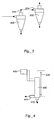
- a two-stage separation can be carried out by direct connection of the first cyclone 305 overflow 310 to the feed 315 of the second hydrocyclone 320, as shown in FIG. 3 .
- a two-stage serial connection allows a second separation to occur in the second hydrocyclone to further separate the media particles into narrower size ranges. If the separation removes 90% of a given density of particle from the overflow each time it passes through the hydrocyclone, a second separation of the overflow has the effect of removing 90% of the remaining material for a net removal of 99%.
- connecting the overflow of the first hydrocyclone to the feed of the second cyclone results in the separation in the second hydrocyclone taking place at a lower density than the separation in the first, since the overflow of the first cyclone contains more water and is less dense than the feed.
- a slurried particulate solid media can be stabilized for use in a separator system such as that in FIG. 3 by first passing the slurry through the system and removing the portion of the media that reports to underflow.
- the system can be designed to allow valves to redirect the two cyclone underflows to storage only during media classification. Once the media has been prepared, all media from both underflows and the overflow is returned to the separation feed tank.
- the headbox is located above the second hydrocyclone by approximately 10 diameters of the second cyclone, which is a sufficient head height to drive many separation cyclones.
- the headbox which drives it, would be approximately 10 x 25.4 cm or 254 cm above the cyclone inlet.
- This configuration has the advantage of not providing additional pressure to the underflow of the first cyclone that may drive more fluid than is desired out the first underflow. It also allows the formation of an air core in the first cyclone that increases separation performance.
- this headbox configuration requires a great deal of vertical height -- in the case of a 38 cm diameter cyclone, almost 4 meters of additional vertical clearance would be required for installation of such a system.
- a practical difficulty of feeding hydrocyclones with overflows in series is that a high pressure is required and pumps capable of handling both abrasive and coarse solids tend not to be well, suited to the high pressures required to drive multiple stages. This is true whether the hydrocyclones are directly connected or connected via a headbox.
- This difficulty may be overcome if, instead of a hydrocyclone, a cylindrical vortex separator as described in U.S. Patent No. 6,238,579 is used. This device has the advantage of requiring much less pressure to drive the separation. As little as 1.5 meters of vertical distance is needed to drive a cylindrical vortex separator with a flow rate equivalent to the rate found with a 38 cm hydrocyclone.
- This 1.5 meters is measured from the heavy product exit port, which may be placed at the bottom of the separator.
- the outlet of the first hydrocyclone can be positioned 0.5 meters above the top of the cylindrical vortex separator.
- FIG. 4 One example of a vertically oriented cylindrical vortex separator is shown in FIG. 4 .
- the feed material enters headbox 405 and is fed to the cylindrical vortex 400, where the separation process causes the heavy product to exit at port 410 while the light product exits a second port 415.
- Distance 420 is measured from the headbox 405 to light port exit 415.
- the combination of a hydrocyclone overflow feeding a headbox which feeds a cylindrical vortex separator enables a much more practical two-stage separation as both the vertical clearance and the pressure requirement of the pump are greatly reduced.
- This configuration has another advantage in that the cylindrical vortex separator delivers between 60 and 90 % of feed fluid to the heavy product, whereas a hydrocyclone delivers between 60 and 90% of the fluid to the light product.
- the cylindrical vortex separator thus acts as a dewatering unit for light products just as hydrocyclones are used as a dewatering device for heavy products.
- a hydrocyclone delivers the heavy product from a wet separation unit and its overflow is sent to a cylindrical vortex separator that delivers a light product from the unit and recirculates the heavy product to the feed tank
- approximately half of the fluid sent through the system does not require dewatering to capture solids. This represents a significant cost savings by simplifying the dewatering screener and potentially simplifying the rinse system required.
- a hydrocyclone with its overflow feeding a cylindrical vortex separator via a dewatering box is used on a water only separation system, both heavy and light products may be sent directly to spin dryers if plastic materials are being processed and a separate dewatering unit is not required before the spin dryer.
- This two-stage system requires only approximately 1 meter more vertical clearance than a single stage system. While the two-stage system requires a slightly higher pressure on the pump, it yields a substantially more precise separation when compared to a single stage system.
- the separation in the first cyclone takes place at a higher density than the separation in the second cyclone since the coarse particles in the slurry tend to report to the underflow of the first separator. If a density monitoring device is placed on the inlet to the second cyclone, a very precisely controlled separation can be made in the second cyclone. The separation which takes place on the first cyclone is less precise because the coarse media precipitates in this stage (resulting in a high differential and offset).
- a first stage separation which removes heavy impurities (such as rubber, metal, PVC and circuit boards from mixed plastics) can precede a second stage separation at a very precise and lower density.
- a mixture of particles contains three polymer types, A, B and C, having densities of 1.20,1.11 and 1.09 g/cc, respectively
- a classified media having a very coarse media fraction added can be used to produce a three-way separation.
- the mixture of particles and media (including the added very coarse fraction) is introduced into a first cyclone, where the most of densest polymer A and substantially all of the very coarse media particles report to the underflow.
- the overflow which includes less dense plastics B and C.
- This overflow which now consists of less dense plastics B and C in the original classified media is fed into the second cyclone, where the B particles now report mostly to the underflow and the C particles report mostly to the overflow.
- the two cyclone system has separated the mixed particles into three streams of A, B and C polymers.
- the same method can be used to separate out heavy impurities (such as rubber, metal, PVC and circuit boards from mixed plastics) in the first cyclone and separate two polymers types or grades in the second cyclone.
- One method of altering the density of the separation is to restrict the apex of the first cyclone.
- the apex When the apex is restricted, the quantity of water which flows to underflow is reduced, but (within limits) the recovery of very coarse solids is not substantially diminished.
- a single separation unit can perform cyclonic separations at two different densities simultaneously (i.e., the lighter fraction containing less dense polymers A and B can be fed back into the first cyclone in the example described above), with the second separation occurring at a lower density and more precisely separating the mixture particles.
- Three products are produced: the high density heavies, the middle range density bracketed product, and the lower density lights.
- the classification media can be regenerated after it has been used in one or more density separations by subjecting the slurry containing the media to the same classification conditions that were originally used to classify the media to generate a controlled particle size distribution.
- fine and coarse particles generated or introduced during the course of one or more separations for example, fine particles generated by abrasion of larger media particles during mixture separations, or coarse particles introduced as contaminants - can be removed and the usefulness of the media can be maintained over multiple separations.
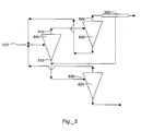
- separators can be fed by the overflow 510 and the underflow 515 from the first stage separation cyclone 505, as shown in FIG. 5 .
- underflow. 515 from first stage separator 505 includes less water than feed fluid 520 into first stage separator 505 such that the density of underflow 515 is considerably higher than the density of feed 520.
- Overflow 510 has more water than feed fluid 520 and is thus less dense, but the density of overflow 510 differs less from the density of feed 520 than does the density of underflow 515. This causes feed 520 into the first stage and overflow-fed separator 525 to differ from feed 530 into underflow-fed separator 535.
- fluid can be removed from overflow 540 of second stage overflow-fed hydrocyclone 525, for example, with dewatering screen unit 550, and the liquid can be added to the feed of underflow-fed separator 535 to correct the underflow-fed feed density.
- a dewatering screen unit can be placed on the underflow discharge from the second stage overflow--fed separator to equalize the density and allow sufficient flow for the three feeds
- the fluid removed with this dewatering box is sent to the headbox for the second stage underflow-fed separator. Adding this fluid supplements the feed into the underflow-fed separator and enables the second stage underflow unit to operate, particularly if a slurried dense media is used as the separation fluid. If no fluid is added to the second stage underflow-fed separator, the separation density at the second stage underflow-fed separator is higher than in the first stage separator and the underflow-fed separator. Thus, the fluid from the large volume discharge of the second stage overflow-fed separator corrects the density of the feed into the second stage underflow-fed separator and allows a second separation stage at the same or similar density as the first stage separator.
- a dewatering screen or unit actually removes fluid as opposed to merely removing water.
- This fluid contains the density adjusting slurried media which has a much finer particle size than the openings on a standard dewatering screener.
- the openings on such a dewatering screener are generally larger than 1000 microns.
- the second stage separators used in the process described above can be cylindrical vortex separators. If a hydrocyclone is used as the second stage overflow-fed separator, the water from the overflow of this separator can be de-watered and sent to the headbox of the second stage underflow-fed separator.
- the second stage underflow separator can either be a hydrocylone or a cylindrical vortex separator.
- a hydrocyclone reports a majority of fluid to the overflow
- a cylindrical vortex separator reports a majority of the feed fluid to the underflow.
- the first stage separator is a cylindrical vortex separator or other centrifugal separator that delivers a higher fraction of fluid to the underflow
- the fluid from the higher volume discharge stream from the second stage underflow-fed separator can be sent to the head box of the second stage overflow separator.
- one pump can be used for the entire multistage process.
- conventional separation processes typically require one pump required for each separator, increasing the cost and complexity of the separation equipment.
- the mixture particles can be rinsed on a screen including a first portion that functions as a "dewatering" section.
- the fluid from the dewatering section can be sent back to the separation tank for direct reuse.
- a portion of this screened fluid can be diverted to a rinse water system.
- the rinse water system includes a separate tank to capture the diverted fluid and deliver it to a rinse pump.
- the rinse pump can pressurize the fluid and feed a separate hydrocyclone that is configured such that it precipitates a much smaller diameter particle than is used with the generally larger hydrocyclones for separation of the mixture and potentially for removal of the coarse fraction of the media.
- the rinse hydrocyclone can be used to accomplish several functions.
- the rinse water can be used to spray the mixture particles in order to liberate more of the media from the wet solids.
- This rinse water system is also a convenient way to control the density of the fluid in the main separation unit. If the density is found to be too low, a portion of the rinse water can be diverted from the process to concentrate the fluid in the tank. If the density of the main separation fluid is too high, a portion of the underflow can be diverted from the process to dilute the separation fluid.
- the rinse cyclone can also be used to remove media that is too fine (generally under approximately 5 microns for magnetite slurries) during media classification, as discussed above.
- the diversion system can be used to send the overflow from an unclassified media to a settling system. This diversion system can be automatically activated if a density monitor (such as a nuclear density meter) is placed on the rinse cyclone overflow. If the overflow density is above a given point (approximately 1.01 g/cc for example) the overflow is automatically diverted and fresh rinse water is substituted. This substitution does not take place if the main separation fluid loop density monitor indicates that the fluid is too dilute.
- a density monitor such as a nuclear density meter
- the character of the media can be controlled and maintained and the density of the main separation loop can be maintained. This has substantial advantages over more expensive magnetic media concentration systems designed to concentrate only ferromagnetic particles for recovery since particles are concentrated by size.
- the rinse water controlled system enables the use of any particulate solid as a media regardless of its magnetic properties.
- the media may be initially classified using this straightforward approach and tuned to remove problematic fine materials.
- the same equipment can then be used to continuously remove fines which are created by the process or are added to the system by the feed. This allows for regeneration and reuse of the slurry.
- the use of a rinse spray substantially increases the recovery of slurry particles and reduces abrasion damage to downstream equipment.
- the mixture particles, if they are plastic, are sent to a variety of centrifugal dryer called a spin dryer which includes a central rotating paddle arrangement inside a stationary screen cylinder.
- the screen cylinder is oriented with its axis vertical.
- Magnetite with a particle size distribution ranging from 0.1 to 100 microns was placed in water and stirred. The slurry was allowed to settle for a few minutes and the supernatant fluid was poured into a second beaker. This slurry was allowed to settle for a few minutes and the supernatant fluid was poured into a third beaker. Each beaker contained either a coarse, mid or fine media size fractions.
- Table 2 shows the charge per mass on the pellets exposed to water, fine and course particles. The charge is less for the pellets exposed to fine particles, suggesting some effect of surface contamination.
- Table 2 Charge per mass of dried polypropylene pellets after exposure to water, fine magnetite media and coarse magnetite media sample charge per mass (nC/g) water only -0.36 fine media -0.17 coarse media -0.34
- a 15 inch D15B model Hydrocyclone manufactured by Krebs Engineers, Arlington, AZ with a 6 inch vortex finder, an 11 square inch inlet and a 4.5 inch apex is fed at a pressure of approximately 7 psi magnetite, removing particles with a diameter above approximately 30 microns.
- additional particles, down to approximately 25 microns can be removed to create a very closely sized 5-25 micron media by repeatedly processing or decreasing the separation cut-point by increasing the feed rate or changing another cyclone separation parameter, as described in Table 1.
- the hydrocyclone is oriented at approximately 22 degrees from the horizontal. The hydrocyclone distributes approximately half of 30-micron particles to the underflow with a higher percentage of coarser particles to the underflow. Approximately 30-40 % of the total fluid is sent to the underflow, thus a particle with only 30-40 % recovery to underflow would not be effectively classified because it reports with the fluid and is not acted upon by the cyclone.
- a model D4B-12 hydrocyclone manufactured by Krebs Engineers with a 1.2 square inch inlet area, a 1.25 inch vortex fmder, and fed at a pressure of approximately 30 psi is expected to recover approximately half of the 10 micron particles of a magnetite slurry to underflow.
- this cyclone sends approximately 10 percent of the total fluid to underflow.
- it concentrates the particles coarser than 10 microns substantially and can have very little ability to capture 5 micron and smaller particles in the underflow.
- Approximately 10 % of all smaller particles are delivered to underflow because they travel with the fluid that reports to underflow. With each pass a fraction between 50 and 90 percent of all particles below 10 microns is removed from the media reporting to underflow.
- 1-5 passes through the cyclone the magnetite recovered to underflow would be substantially free of particles 5 micron and under.
Landscapes
- Engineering & Computer Science (AREA)
- Mechanical Engineering (AREA)
- Environmental & Geological Engineering (AREA)
- Separation Of Solids By Using Liquids Or Pneumatic Power (AREA)
- Addition Polymer Or Copolymer, Post-Treatments, Or Chemical Modifications (AREA)
- Combined Means For Separation Of Solids (AREA)
- Processing And Handling Of Plastics And Other Materials For Molding In General (AREA)
- Sampling And Sample Adjustment (AREA)
- Analysing Materials By The Use Of Radiation (AREA)
- Cyclones (AREA)
Claims (16)
- Procédé pour séparer un mélange, ledit procédé comprenant:l'exécution d'une ou de plusieurs séparations de classification grossière sur une suspension comprenant un liquide de séparation et une ou plusieurs matières porteuses particulaires, dans lequel l'exécution de la ou des séparations de classification grossière sépare de la suspension une fraction grossière contenant des particules grossières de la ou de plusieurs matières porteuses, lesdites particules grossières possédant une dimension de particule supérieures à un premier seuil de dimension de particules;l'exécution d'une ou de plusieurs séparations de classification fines pour séparer de la suspension une fraction fine contenant des particules fines de la ou de plusieurs matières porteuses, lesdites particules fines possédant une dimension de particules inférieure à un second seuil de dimension de particules, sachant que la ou les séparations de classification grossière séparant de la suspension une fraction grossière et la ou les séparations de classification fines pour séparer de la suspension une fraction fine produisent un porteur classifié présentant une répartition de dimensions de particules contrôlée des matières porteuses particulaires;la combinaison du porteur classifié avec un mélange devant être séparé pour générer un mélange de séparation, sachant que le mélange devant être séparé comprend du plastique;l'exécution d'une ou de plusieurs séparations par densité sur le mélange de séparation;dans lequel l'exécution de la ou des séparations de classification grossière sur la suspension et de la ou des séparations de classification fines sur la suspension ou l'exécution de la ou des séparations par la densité sur le mélange de séparation comprend:la séparation de la suspension ou du mélange de séparation dans un premier séparateur par densité pour générer une première fraction et une seconde fraction;la séparation de la première fraction dans un second séparateur par densité pour générer une troisième fraction;la récupération de liquide depuis la troisième fraction;la combinaison du liquide récupéré avec la seconde fraction, etla séparation de la seconde fraction dans un troisième séparateur par densité.
- Procédé selon la revendication 1, comprenant en outre:la régénération du media classifié par l'exécution d'une séparation de classification du porteur après l'exécution d'au moins une séparation par densité de la ou des séparations par densité sur le mélange de séparation.
- Procédé selon l'une des revendications 1-2, comprenant en outre:la régénération du porteur classifié par exécution d'une séparation de classification du porteur après l'exécution d'au moins une séparation par densité de la ou de plusieurs séparations par densité sur le mélange de séparation, y compris la suppression de matière particulaire depuis le porteur classifié, possédant une dimension de particules inférieure à un seuil de dimension de particules fine.
- Procédé selon la revendication 3, comprenant en outre:avant l'exécution d'une première séparation par densité de la ou des séparations par densité sur le mélange de séparation, l'addition au mélange d'une fraction très grossière de la ou de plusieurs matières porteuses, ladite fraction très grossière contenant des particules de porteur liées substantiellement à l'écoulement de fond du séparateur.
- Procédé selon la revendication 3, dans lequel:le premier seuil de dimension de particules et le second seuil de particules sont déterminés sur la base de paramètres d'un système de séparation.
- Procédé selon l'une des revendications 1-5, dans lequel:l'exécution d'une ou de plusieurs séparations de classification grossière sur la suspension, l'exécution d'une ou de plusieurs séparations de classification fine sur la suspension ou l'exécution d'une ou de plusieurs séparations par densité sur le mélange de séparation comprend la séparation de la suspension ou du mélange de séparation par utilisation d'un ou de plusieurs séparateurs hydrocyclones.
- Procédé selon l'une des revendications 1-6, dans lequel:l'exécution d'une ou de plusieurs séparations de classification grossière sur la suspension, l'exécution d'une ou de plusieurs séparations de classification fine sur la suspension ou l'exécution d'une ou de plusieurs séparations par densité sur le mélange de séparation comprend la séparation de la suspension ou du mélange de séparation par utilisation d'un ou de plusieurs séparateurs tourbillonnaires cylindriques.
- Procédé selon l'une des revendications 1-7, dans lequel:l'exécution d'une ou de plusieurs séparations de classification grossière sur la suspension, l'exécution d'une ou de plusieurs séparations de classification fine sur la suspension ou l'exécution d'une ou de plusieurs séparations par densité sur le mélange de séparation comprend la séparation de la suspension ou du mélange de séparation par utilisation d'un ou de plusieurs séparateurs hydrocyclones et d'un ou de plusieurs séparateurs tourbillonnaires cylindriques.
- Procédé selon l'une des revendications 1-8, dans lequel:l'exécution d'une ou de plusieurs séparations de classification grossière sur la suspension ou l'exécution d'une ou de plusieurs séparations de classification fine sur la suspension comprend la séparation de la suspension par utilisation d'un arrangement d'un ou de plusieurs séparateurs par densité, etl'exécution d'une ou de plusieurs séparations par densité sur le mélange de séparation comprend la séparation du mélange de séparation par utilisation de l'arrangement d'un ou de plusieurs séparateurs par densité.
- Procédé selon l'une des revendications 1-9, dans lequel:la ou plusieurs matières porteuses particulaires comprennent l'une ou plusieurs des matières que sont la magnétite, le dioxyde de titane, le sable ou le ferrosilicate.
- Procédé selon l'une des revendications 1-10, dans lequel:le mélange devant être séparé comprend un ou plusieurs métaux.
- Procédé selon l'une des revendications 1-11, dans lequel:la ou plusieurs matières porteuses particulaires comprennent de la magnétite et le porteur classifié comprend des particules de magnétite présentant une répartition de dimensions de particules de l'ordre de 5 microns environ à 30 microns environ.
- Procédé selon la revendication 12, dans lequel:la ou plusieurs matières porteuses particulaires comprennent de la magnétite et le porteur classifié comprend des particules de magnétite présentant une répartition de dimensions de particules de l'ordre de 5 microns environ à 25 microns environ.
- Procédé selon la revendication 1, dans lequel:la séparation de la première fraction dans un second séparateur par densité comprend la génération de la troisième et d'une quatrième fraction, ladite troisième fraction contenant une quantité de liquide supérieure à celle de la quatrième fraction.
- Procédé selon la revendication 1, dans lequel:le premier séparateur par densité est un hydrocyclone et les second et troisième séparateurs par densité sont des séparateurs tourbillonnaires cylindriques.
- Procédé selon la revendication 1, dans lequel:le premier séparateur par densité est un séparateur tourbillonnaire cylindrique et les second et troisième séparateurs par densité sont des séparateurs hydrocyclones.
Applications Claiming Priority (3)
| Application Number | Priority Date | Filing Date | Title |
|---|---|---|---|
| US39780802P | 2002-07-22 | 2002-07-22 | |
| US397808P | 2002-07-22 | ||
| PCT/US2003/022920 WO2004009200A2 (fr) | 2002-07-22 | 2003-07-22 | Regulation de la granulometrie de milieux dans les separations de milieux denses sous forme de boues |
Publications (3)
| Publication Number | Publication Date |
|---|---|
| EP1558352A2 EP1558352A2 (fr) | 2005-08-03 |
| EP1558352A4 EP1558352A4 (fr) | 2009-01-21 |
| EP1558352B1 true EP1558352B1 (fr) | 2010-09-29 |
Family
ID=30771120
Family Applications (1)
| Application Number | Title | Priority Date | Filing Date |
|---|---|---|---|
| EP20030765926 Expired - Lifetime EP1558352B1 (fr) | 2002-07-22 | 2003-07-22 | Regulation de la granulometrie de milieux dans les separations de milieux denses sous forme de boues |
Country Status (10)
| Country | Link |
|---|---|
| US (1) | US7111738B2 (fr) |
| EP (1) | EP1558352B1 (fr) |
| JP (2) | JP4865224B2 (fr) |
| CN (1) | CN1688392B (fr) |
| AT (1) | ATE482755T1 (fr) |
| AU (1) | AU2003254114A1 (fr) |
| DE (1) | DE60334393D1 (fr) |
| ES (1) | ES2356073T3 (fr) |
| HK (1) | HK1081477A1 (fr) |
| WO (1) | WO2004009200A2 (fr) |
Families Citing this family (44)
| Publication number | Priority date | Publication date | Assignee | Title |
|---|---|---|---|---|
| US7884140B2 (en) | 2002-04-12 | 2011-02-08 | Mba Polymers, Inc. | Compositions of materials containing recycled plastics |
| JP2006505419A (ja) * | 2002-04-12 | 2006-02-16 | エムビーエー ポリマーズ, インコーポレイテッド | ブラスチックの多段階分離 |
| US7736501B2 (en) | 2002-09-19 | 2010-06-15 | Suncor Energy Inc. | System and process for concentrating hydrocarbons in a bitumen feed |
| CA2471048C (fr) | 2002-09-19 | 2006-04-25 | Suncor Energy Inc. | Cyclone d'hydrocarbures de mousse bitumineuse |
| FR2860994B1 (fr) * | 2003-10-15 | 2007-07-13 | Galloo Plastics | Procede de separation selective de materiaux organiques usages fragmentes au moyen de suspensions aqueuses denses |
| FR2863509B1 (fr) * | 2003-12-10 | 2007-07-13 | Galloo Plastics | Procede de separation selective de materiaux polymeres fragmentes en particulier usages, au moyen de suspensions aqueuses denses dynamiquement stabilises |
| US7380669B2 (en) * | 2004-06-22 | 2008-06-03 | Hacking Jr Earl L | Apparatus and method for sorting and recombining minerals into a desired mixture |
| CA2476194C (fr) | 2004-07-30 | 2010-06-22 | Suncor Energy Inc. | Dispositif de traitement du minerai a crible-classeur a rouleaux |
| US20060163118A1 (en) * | 2005-01-26 | 2006-07-27 | Eastman Kodak Company | Particulate separation processes and apparatus |
| KR100636021B1 (ko) * | 2005-02-04 | 2006-10-18 | 삼성전자주식회사 | 사이클론, 이를 갖는 슬러리 분류 장치, 이 장치를 이용한슬러리 공급 시스템 및 방법 |
| US8393561B2 (en) * | 2005-11-09 | 2013-03-12 | Suncor Energy Inc. | Method and apparatus for creating a slurry |
| US8875903B2 (en) * | 2007-03-19 | 2014-11-04 | Palo Alto Research Center Incorporated | Vortex structure for high throughput continuous flow separation |
| US7487929B1 (en) | 2007-09-27 | 2009-02-10 | Long Edward W | Grinding circuit with cyclone and density separator classification system and method |
| US7896955B2 (en) * | 2007-11-12 | 2011-03-01 | General Electric Company | Low temperature solids removal system for gasification |
| WO2009124015A2 (fr) * | 2008-03-31 | 2009-10-08 | Mba Polymers, Inc. | Procédés, systèmes, et dispositifs de séparation de matériaux en utilisant des propriétés magnétiques et frictionnelles |
| JP4909943B2 (ja) * | 2008-05-20 | 2012-04-04 | 株式会社東芝 | 固液分離装置 |
| CA2640514A1 (fr) * | 2008-09-18 | 2010-03-18 | Kyle Alan Bruggencate | Methode et appareil de traitement de l'alimentation de minerai |
| US20100223206A1 (en) * | 2008-11-14 | 2010-09-02 | Sharrock Michael P | Method of providing and selecting particles to increase signal-to-noise ratio in magnetic recording media |
| CN101417258B (zh) * | 2008-11-20 | 2011-09-07 | 胡智勇 | 用于超细功能粉体制备的湿法精确分级工艺 |
| US8114915B2 (en) * | 2008-12-05 | 2012-02-14 | Exxonmobil Research And Engineering Company | Method and system for handling slurries of varying liquid rates and solids content |
| US20100155307A1 (en) * | 2008-12-18 | 2010-06-24 | Soto Jorge L | Method and system for fines management in slurry processes |
| US8119014B2 (en) * | 2008-12-23 | 2012-02-21 | Exxonmobil Research And Engineering Company | Systems and methods to remove liquid product and fines from a slurry reactor |
| CA2689021C (fr) | 2009-12-23 | 2015-03-03 | Thomas Charles Hann | Appareil et procede de regulation de debit par le truchement d'une caisse aspirante |
| US8708159B2 (en) * | 2011-02-16 | 2014-04-29 | Oakwood Laboratories, Llc | Manufacture of microspheres using a hydrocyclone |
| GB201220315D0 (en) * | 2012-11-12 | 2012-12-26 | Crorme Ltd | Extruding plastics |
| US20170136498A1 (en) * | 2014-03-31 | 2017-05-18 | Hosokawa Micron Corporation | Classifier |
| CN104107764A (zh) * | 2014-07-22 | 2014-10-22 | 四川龙蟒钛业股份有限公司 | 一种提高钛白粉涂膜平整度和光泽度的方法 |
| CN104483165B (zh) * | 2014-11-21 | 2017-07-28 | 江苏博迁新材料股份有限公司 | 一种超细磁性粉体中大粒径粉的取样方法 |
| US20210025028A1 (en) | 2016-02-15 | 2021-01-28 | Uranium Beneficiation Pty Ltd | Uranium processing using hydrocyclone beneficiation |
| AU2017100575B4 (en) * | 2016-02-15 | 2017-07-27 | Uranium Beneficiation Pty Ltd | Beneficiation Process For Enhancing Uranium Mineral Processing |
| AU2017203383B2 (en) * | 2016-02-15 | 2017-08-03 | Uranium Beneficiation Pty Ltd | Beneficiation process for enhancing uranium mineral processing |
| US10399881B2 (en) * | 2016-12-14 | 2019-09-03 | General Electric Company | Methods and systems for separating solid particulates from waste water |
| US10520484B2 (en) * | 2016-12-21 | 2019-12-31 | Halliburton Energy Services, Inc. | Aging testing apparatus and use thereof |
| WO2019093726A1 (fr) * | 2017-11-07 | 2019-05-16 | 한국지질자원연구원 | Procédé de fabrication de microparticules hautement fonctionnelles revêtues de carbonate de calcium à l'aide de boues de déchets en béton |
| KR101896689B1 (ko) * | 2017-11-07 | 2018-09-07 | 한국지질자원연구원 | 폐콘크리트 슬러지를 이용한 탄산칼슘 코팅 고기능성 미세입자 제조방법 |
| KR101957473B1 (ko) * | 2018-07-20 | 2019-03-12 | 한국지질자원연구원 | 폐콘크리트 슬러지를 이용한 탄산칼슘 코팅 고기능성 미세입자 제조방법 |
| CN109225642B (zh) * | 2018-10-16 | 2019-09-03 | 江南大学 | 一种超细粉体湿法静电分级装置 |
| CN110302895A (zh) * | 2019-07-15 | 2019-10-08 | 马鞍山市新桥工业设计有限公司 | 一种分离含有杂质玻璃颗粒的循环利用装置及方法 |
| GB2589097B (en) * | 2019-11-19 | 2022-02-23 | Cde Global Ltd | Method and apparatus for washing and grading sand |
| KR20220114001A (ko) * | 2019-12-09 | 2022-08-17 | 아크보텍 피티와이 엘티디 | 수용성 물질로부터 오염물질을 제거하기 위한 방법 및 장치 |
| CN113019671B (zh) * | 2021-03-19 | 2023-04-07 | 神华神东煤炭集团有限责任公司 | 一种全重介选煤工艺介质的筛选方法及筛选系统 |
| CN113916308B (zh) * | 2021-12-14 | 2022-03-29 | 四川凌耘建科技有限公司 | 一种多井式两相流计量撬及其计量方法 |
| CN115970881B (zh) * | 2023-03-16 | 2023-07-07 | 天津美腾科技股份有限公司 | 一种分选系统及精煤质量调控方法 |
| CN117839881B (zh) * | 2024-03-07 | 2024-05-03 | 山东深海生物科技股份有限公司 | 一种合成生物法生产5-氨基乙酰丙酸的发酵液精制装置 |
Family Cites Families (10)
| Publication number | Priority date | Publication date | Assignee | Title |
|---|---|---|---|---|
| FI80837C (fi) * | 1985-05-03 | 1990-08-10 | Larox Ag | Hydrauliskt klassifiseringsfoerfarande och -anordning. |
| US5794791A (en) * | 1987-11-30 | 1998-08-18 | Genesis Research Corporation | Coal cleaning process |
| NL9300041A (nl) * | 1993-01-08 | 1994-08-01 | Heidemij Realisatie Bv | Behandeling van organisch materiaal. |
| US5819945A (en) * | 1995-08-31 | 1998-10-13 | University Of British Columbia | Bimodal dense medium for fine particles separation in a dense medium cyclone |
| DE19606415A1 (de) * | 1996-02-21 | 1997-08-28 | Deutz Ag | Effektive Kunststoffsortierung |
| US7172143B2 (en) * | 1996-07-22 | 2007-02-06 | Antoine Vandeputte | Method and plant for separating polymeric materials |
| US5894996A (en) * | 1997-08-13 | 1999-04-20 | Empak, Inc. | Method and apparatus for reclaiming plastic |
| US6335376B1 (en) * | 1998-05-26 | 2002-01-01 | Mba Polymers, Inc. | Apparatus and method for enhancing partitioning of different polymeric materials from a mixture by density differential alteration |
| JP2001020262A (ja) * | 1999-07-08 | 2001-01-23 | Ishikawajima Harima Heavy Ind Co Ltd | ダム堆積土砂洗浄システム |
| JP2002239906A (ja) * | 2001-02-13 | 2002-08-28 | Ishikawajima Hanyoki Service Co Ltd | ラップ砥粒スラリーの再生方法及び装置 |
-
2003
- 2003-07-22 AU AU2003254114A patent/AU2003254114A1/en not_active Abandoned
- 2003-07-22 AT AT03765926T patent/ATE482755T1/de active
- 2003-07-22 WO PCT/US2003/022920 patent/WO2004009200A2/fr active Application Filing
- 2003-07-22 JP JP2004523300A patent/JP4865224B2/ja not_active Expired - Fee Related
- 2003-07-22 CN CN038171473A patent/CN1688392B/zh not_active Expired - Fee Related
- 2003-07-22 DE DE60334393T patent/DE60334393D1/de not_active Expired - Lifetime
- 2003-07-22 ES ES03765926T patent/ES2356073T3/es not_active Expired - Lifetime
- 2003-07-22 EP EP20030765926 patent/EP1558352B1/fr not_active Expired - Lifetime
-
2004
- 2004-02-09 US US10/775,613 patent/US7111738B2/en not_active Expired - Fee Related
-
2006
- 2006-02-02 HK HK06101445A patent/HK1081477A1/xx unknown
-
2010
- 2010-02-10 JP JP2010027968A patent/JP2010104990A/ja active Pending
Also Published As
| Publication number | Publication date |
|---|---|
| JP4865224B2 (ja) | 2012-02-01 |
| US7111738B2 (en) | 2006-09-26 |
| AU2003254114A8 (en) | 2004-02-09 |
| WO2004009200A2 (fr) | 2004-01-29 |
| HK1081477A1 (en) | 2006-05-19 |
| ATE482755T1 (de) | 2010-10-15 |
| EP1558352A2 (fr) | 2005-08-03 |
| ES2356073T3 (es) | 2011-04-04 |
| JP2005533640A (ja) | 2005-11-10 |
| WO2004009200A3 (fr) | 2005-06-09 |
| CN1688392A (zh) | 2005-10-26 |
| AU2003254114A1 (en) | 2004-02-09 |
| DE60334393D1 (de) | 2010-11-11 |
| EP1558352A4 (fr) | 2009-01-21 |
| CN1688392B (zh) | 2010-06-23 |
| US20040164005A1 (en) | 2004-08-26 |
| JP2010104990A (ja) | 2010-05-13 |
Similar Documents
| Publication | Publication Date | Title |
|---|---|---|
| EP1558352B1 (fr) | Regulation de la granulometrie de milieux dans les separations de milieux denses sous forme de boues | |
| US8322642B2 (en) | Arrangement for classifying particles in a pyrolysed char | |
| US20190329267A1 (en) | Method and apparatus for washing and grading silica sand for glass production | |
| US4746421A (en) | Density classification of particulate materials by elutriation methods | |
| CA2252690A1 (fr) | Systeme de preparation de charbon | |
| FI80837C (fi) | Hydrauliskt klassifiseringsfoerfarande och -anordning. | |
| AU2008291673B2 (en) | Method for improving flotation cell performance | |
| CA1085317A (fr) | Concentrateur et methode de separation par centrifugation | |
| CN109092547A (zh) | 煤泥分选方法以及煤泥分选系统 | |
| JPH11503366A (ja) | 物質の遠心分離方法 | |
| KR100695917B1 (ko) | 순환모래의 이물질 분류방법 및 그 분류장치 | |
| CA3192983A1 (fr) | Methode de recyclage du plastique pour traiter les dechets de plastique | |
| EP0874692B1 (fr) | Procede de classification de grains tres fins par voie humide | |
| CZ287352B6 (en) | Recovery process of starting materials from a flow of residual or entrapped substances containing various matters and obtained during production of paper as well as apparatus for making the same | |
| Grotjohann et al. | Allflux separator—A new way to process heavy minerals | |
| JP3495683B2 (ja) | 破砕フレークの分離装置 | |
| CA1172615A (fr) | Enrichissement de minerai | |
| CA1195636A (fr) | Methode et installation de separation de substances minerales | |
| CN114345542A (zh) | 一种单系统选矿工艺 | |
| CN109092550A (zh) | 一种粗精煤离心液回收系统及其回收方法 | |
| Covey | Contaminant Removal By Centrifugal Cleaners | |
| GB2172519A (en) | Filter aid |
Legal Events
| Date | Code | Title | Description |
|---|---|---|---|
| PUAI | Public reference made under article 153(3) epc to a published international application that has entered the european phase |
Free format text: ORIGINAL CODE: 0009012 |
|
| 17P | Request for examination filed |
Effective date: 20050221 |
|
| AK | Designated contracting states |
Kind code of ref document: A2 Designated state(s): AT BE BG CH CY CZ DE DK EE ES FI FR GB GR HU IE IT LI LU MC NL PT RO SE SI SK TR |
|
| AX | Request for extension of the european patent |
Extension state: AL LT LV MK |
|
| DAX | Request for extension of the european patent (deleted) | ||
| REG | Reference to a national code |
Ref country code: HK Ref legal event code: DE Ref document number: 1081477 Country of ref document: HK |
|
| A4 | Supplementary search report drawn up and despatched |
Effective date: 20081219 |
|
| RIC1 | Information provided on ipc code assigned before grant |
Ipc: B29C 47/00 20060101ALI20081215BHEP Ipc: B03B 5/44 20060101ALI20081215BHEP Ipc: B01D 1/00 20060101AFI20040211BHEP Ipc: B03B 5/34 20060101ALI20081215BHEP Ipc: B03C 7/00 20060101ALI20081215BHEP Ipc: B29B 17/02 20060101ALI20081215BHEP |
|
| 17Q | First examination report despatched |
Effective date: 20090430 |
|
| GRAP | Despatch of communication of intention to grant a patent |
Free format text: ORIGINAL CODE: EPIDOSNIGR1 |
|
| GRAS | Grant fee paid |
Free format text: ORIGINAL CODE: EPIDOSNIGR3 |
|
| GRAA | (expected) grant |
Free format text: ORIGINAL CODE: 0009210 |
|
| AK | Designated contracting states |
Kind code of ref document: B1 Designated state(s): AT BE BG CH CY CZ DE DK EE ES FI FR GB GR HU IE IT LI LU MC NL PT RO SE SI SK TR |
|
| REG | Reference to a national code |
Ref country code: GB Ref legal event code: FG4D |
|
| REG | Reference to a national code |
Ref country code: CH Ref legal event code: EP |
|
| REG | Reference to a national code |
Ref country code: IE Ref legal event code: FG4D |
|
| REF | Corresponds to: |
Ref document number: 60334393 Country of ref document: DE Date of ref document: 20101111 Kind code of ref document: P |
|
| REG | Reference to a national code |
Ref country code: HK Ref legal event code: GR Ref document number: 1081477 Country of ref document: HK |
|
| REG | Reference to a national code |
Ref country code: NL Ref legal event code: T3 |
|
| PG25 | Lapsed in a contracting state [announced via postgrant information from national office to epo] |
Ref country code: FI Free format text: LAPSE BECAUSE OF FAILURE TO SUBMIT A TRANSLATION OF THE DESCRIPTION OR TO PAY THE FEE WITHIN THE PRESCRIBED TIME-LIMIT Effective date: 20100929 |
|
| PG25 | Lapsed in a contracting state [announced via postgrant information from national office to epo] |
Ref country code: SI Free format text: LAPSE BECAUSE OF FAILURE TO SUBMIT A TRANSLATION OF THE DESCRIPTION OR TO PAY THE FEE WITHIN THE PRESCRIBED TIME-LIMIT Effective date: 20100929 |
|
| PG25 | Lapsed in a contracting state [announced via postgrant information from national office to epo] |
Ref country code: GR Free format text: LAPSE BECAUSE OF FAILURE TO SUBMIT A TRANSLATION OF THE DESCRIPTION OR TO PAY THE FEE WITHIN THE PRESCRIBED TIME-LIMIT Effective date: 20101230 Ref country code: SE Free format text: LAPSE BECAUSE OF FAILURE TO SUBMIT A TRANSLATION OF THE DESCRIPTION OR TO PAY THE FEE WITHIN THE PRESCRIBED TIME-LIMIT Effective date: 20100929 |
|
| REG | Reference to a national code |
Ref country code: ES Ref legal event code: FG2A Ref document number: 2356073 Country of ref document: ES Kind code of ref document: T3 Effective date: 20110404 |
|
| REG | Reference to a national code |
Ref country code: CH Ref legal event code: NV Representative=s name: ISLER & PEDRAZZINI AG |
|
| PG25 | Lapsed in a contracting state [announced via postgrant information from national office to epo] |
Ref country code: EE Free format text: LAPSE BECAUSE OF FAILURE TO SUBMIT A TRANSLATION OF THE DESCRIPTION OR TO PAY THE FEE WITHIN THE PRESCRIBED TIME-LIMIT Effective date: 20100929 Ref country code: RO Free format text: LAPSE BECAUSE OF FAILURE TO SUBMIT A TRANSLATION OF THE DESCRIPTION OR TO PAY THE FEE WITHIN THE PRESCRIBED TIME-LIMIT Effective date: 20100929 Ref country code: IT Free format text: LAPSE BECAUSE OF FAILURE TO SUBMIT A TRANSLATION OF THE DESCRIPTION OR TO PAY THE FEE WITHIN THE PRESCRIBED TIME-LIMIT Effective date: 20100929 Ref country code: SK Free format text: LAPSE BECAUSE OF FAILURE TO SUBMIT A TRANSLATION OF THE DESCRIPTION OR TO PAY THE FEE WITHIN THE PRESCRIBED TIME-LIMIT Effective date: 20100929 Ref country code: PT Free format text: LAPSE BECAUSE OF FAILURE TO SUBMIT A TRANSLATION OF THE DESCRIPTION OR TO PAY THE FEE WITHIN THE PRESCRIBED TIME-LIMIT Effective date: 20110131 Ref country code: CZ Free format text: LAPSE BECAUSE OF FAILURE TO SUBMIT A TRANSLATION OF THE DESCRIPTION OR TO PAY THE FEE WITHIN THE PRESCRIBED TIME-LIMIT Effective date: 20100929 |
|
| PLBE | No opposition filed within time limit |
Free format text: ORIGINAL CODE: 0009261 |
|
| STAA | Information on the status of an ep patent application or granted ep patent |
Free format text: STATUS: NO OPPOSITION FILED WITHIN TIME LIMIT |
|
| PG25 | Lapsed in a contracting state [announced via postgrant information from national office to epo] |
Ref country code: DK Free format text: LAPSE BECAUSE OF FAILURE TO SUBMIT A TRANSLATION OF THE DESCRIPTION OR TO PAY THE FEE WITHIN THE PRESCRIBED TIME-LIMIT Effective date: 20100929 |
|
| 26N | No opposition filed |
Effective date: 20110630 |
|
| REG | Reference to a national code |
Ref country code: DE Ref legal event code: R097 Ref document number: 60334393 Country of ref document: DE Effective date: 20110630 |
|
| PG25 | Lapsed in a contracting state [announced via postgrant information from national office to epo] |
Ref country code: MC Free format text: LAPSE BECAUSE OF NON-PAYMENT OF DUE FEES Effective date: 20110731 |
|
| REG | Reference to a national code |
Ref country code: IE Ref legal event code: MM4A |
|
| PG25 | Lapsed in a contracting state [announced via postgrant information from national office to epo] |
Ref country code: IE Free format text: LAPSE BECAUSE OF NON-PAYMENT OF DUE FEES Effective date: 20110722 |
|
| PG25 | Lapsed in a contracting state [announced via postgrant information from national office to epo] |
Ref country code: CY Free format text: LAPSE BECAUSE OF EXPIRATION OF PROTECTION Effective date: 20100929 |
|
| PGFP | Annual fee paid to national office [announced via postgrant information from national office to epo] |
Ref country code: LU Payment date: 20130730 Year of fee payment: 11 |
|
| PG25 | Lapsed in a contracting state [announced via postgrant information from national office to epo] |
Ref country code: BG Free format text: LAPSE BECAUSE OF FAILURE TO SUBMIT A TRANSLATION OF THE DESCRIPTION OR TO PAY THE FEE WITHIN THE PRESCRIBED TIME-LIMIT Effective date: 20101229 Ref country code: TR Free format text: LAPSE BECAUSE OF FAILURE TO SUBMIT A TRANSLATION OF THE DESCRIPTION OR TO PAY THE FEE WITHIN THE PRESCRIBED TIME-LIMIT Effective date: 20100929 |
|
| PG25 | Lapsed in a contracting state [announced via postgrant information from national office to epo] |
Ref country code: HU Free format text: LAPSE BECAUSE OF FAILURE TO SUBMIT A TRANSLATION OF THE DESCRIPTION OR TO PAY THE FEE WITHIN THE PRESCRIBED TIME-LIMIT Effective date: 20100929 |
|
| PGFP | Annual fee paid to national office [announced via postgrant information from national office to epo] |
Ref country code: BE Payment date: 20130729 Year of fee payment: 11 Ref country code: NL Payment date: 20130726 Year of fee payment: 11 Ref country code: CH Payment date: 20130729 Year of fee payment: 11 Ref country code: DE Payment date: 20130729 Year of fee payment: 11 Ref country code: ES Payment date: 20130726 Year of fee payment: 11 |
|
| PGFP | Annual fee paid to national office [announced via postgrant information from national office to epo] |
Ref country code: AT Payment date: 20140702 Year of fee payment: 12 |
|
| REG | Reference to a national code |
Ref country code: DE Ref legal event code: R119 Ref document number: 60334393 Country of ref document: DE |
|
| REG | Reference to a national code |
Ref country code: NL Ref legal event code: V1 Effective date: 20150201 |
|
| PG25 | Lapsed in a contracting state [announced via postgrant information from national office to epo] |
Ref country code: LU Free format text: LAPSE BECAUSE OF NON-PAYMENT OF DUE FEES Effective date: 20140722 |
|
| REG | Reference to a national code |
Ref country code: CH Ref legal event code: PL |
|
| PG25 | Lapsed in a contracting state [announced via postgrant information from national office to epo] |
Ref country code: NL Free format text: LAPSE BECAUSE OF NON-PAYMENT OF DUE FEES Effective date: 20150201 |
|
| PG25 | Lapsed in a contracting state [announced via postgrant information from national office to epo] |
Ref country code: CH Free format text: LAPSE BECAUSE OF NON-PAYMENT OF DUE FEES Effective date: 20140731 Ref country code: DE Free format text: LAPSE BECAUSE OF NON-PAYMENT OF DUE FEES Effective date: 20150203 Ref country code: LI Free format text: LAPSE BECAUSE OF NON-PAYMENT OF DUE FEES Effective date: 20140731 |
|
| REG | Reference to a national code |
Ref country code: DE Ref legal event code: R119 Ref document number: 60334393 Country of ref document: DE Effective date: 20150203 |
|
| REG | Reference to a national code |
Ref country code: ES Ref legal event code: FD2A Effective date: 20150828 |
|
| PG25 | Lapsed in a contracting state [announced via postgrant information from national office to epo] |
Ref country code: ES Free format text: LAPSE BECAUSE OF NON-PAYMENT OF DUE FEES Effective date: 20140723 |
|
| REG | Reference to a national code |
Ref country code: AT Ref legal event code: MM01 Ref document number: 482755 Country of ref document: AT Kind code of ref document: T Effective date: 20150722 |
|
| PG25 | Lapsed in a contracting state [announced via postgrant information from national office to epo] |
Ref country code: AT Free format text: LAPSE BECAUSE OF NON-PAYMENT OF DUE FEES Effective date: 20150722 |
|
| REG | Reference to a national code |
Ref country code: FR Ref legal event code: PLFP Year of fee payment: 14 |
|
| PGFP | Annual fee paid to national office [announced via postgrant information from national office to epo] |
Ref country code: GB Payment date: 20160727 Year of fee payment: 14 |
|
| PGFP | Annual fee paid to national office [announced via postgrant information from national office to epo] |
Ref country code: FR Payment date: 20160726 Year of fee payment: 14 |
|
| PG25 | Lapsed in a contracting state [announced via postgrant information from national office to epo] |
Ref country code: BE Free format text: LAPSE BECAUSE OF NON-PAYMENT OF DUE FEES Effective date: 20140731 |
|
| GBPC | Gb: european patent ceased through non-payment of renewal fee |
Effective date: 20170722 |
|
| REG | Reference to a national code |
Ref country code: FR Ref legal event code: ST Effective date: 20180330 |
|
| PG25 | Lapsed in a contracting state [announced via postgrant information from national office to epo] |
Ref country code: GB Free format text: LAPSE BECAUSE OF NON-PAYMENT OF DUE FEES Effective date: 20170722 |
|
| PG25 | Lapsed in a contracting state [announced via postgrant information from national office to epo] |
Ref country code: FR Free format text: LAPSE BECAUSE OF NON-PAYMENT OF DUE FEES Effective date: 20170731 |