EP1557698A2 - Article à traitement anti-réflet - Google Patents
Article à traitement anti-réflet Download PDFInfo
- Publication number
- EP1557698A2 EP1557698A2 EP05075381A EP05075381A EP1557698A2 EP 1557698 A2 EP1557698 A2 EP 1557698A2 EP 05075381 A EP05075381 A EP 05075381A EP 05075381 A EP05075381 A EP 05075381A EP 1557698 A2 EP1557698 A2 EP 1557698A2
- Authority
- EP
- European Patent Office
- Prior art keywords
- article
- recited
- color
- perceived
- coated
- Prior art date
- Legal status (The legal status is an assumption and is not a legal conclusion. Google has not performed a legal analysis and makes no representation as to the accuracy of the status listed.)
- Withdrawn
Links
Images


Classifications
-
- C—CHEMISTRY; METALLURGY
- C03—GLASS; MINERAL OR SLAG WOOL
- C03C—CHEMICAL COMPOSITION OF GLASSES, GLAZES OR VITREOUS ENAMELS; SURFACE TREATMENT OF GLASS; SURFACE TREATMENT OF FIBRES OR FILAMENTS MADE FROM GLASS, MINERALS OR SLAGS; JOINING GLASS TO GLASS OR OTHER MATERIALS
- C03C17/00—Surface treatment of glass, not in the form of fibres or filaments, by coating
- C03C17/22—Surface treatment of glass, not in the form of fibres or filaments, by coating with other inorganic material
- C03C17/225—Nitrides
-
- C—CHEMISTRY; METALLURGY
- C03—GLASS; MINERAL OR SLAG WOOL
- C03C—CHEMICAL COMPOSITION OF GLASSES, GLAZES OR VITREOUS ENAMELS; SURFACE TREATMENT OF GLASS; SURFACE TREATMENT OF FIBRES OR FILAMENTS MADE FROM GLASS, MINERALS OR SLAGS; JOINING GLASS TO GLASS OR OTHER MATERIALS
- C03C17/00—Surface treatment of glass, not in the form of fibres or filaments, by coating
- C03C17/22—Surface treatment of glass, not in the form of fibres or filaments, by coating with other inorganic material
- C03C17/23—Oxides
- C03C17/25—Oxides by deposition from the liquid phase
- C03C17/256—Coating containing TiO2
-
- C—CHEMISTRY; METALLURGY
- C03—GLASS; MINERAL OR SLAG WOOL
- C03C—CHEMICAL COMPOSITION OF GLASSES, GLAZES OR VITREOUS ENAMELS; SURFACE TREATMENT OF GLASS; SURFACE TREATMENT OF FIBRES OR FILAMENTS MADE FROM GLASS, MINERALS OR SLAGS; JOINING GLASS TO GLASS OR OTHER MATERIALS
- C03C17/00—Surface treatment of glass, not in the form of fibres or filaments, by coating
- C03C17/28—Surface treatment of glass, not in the form of fibres or filaments, by coating with organic material
- C03C17/30—Surface treatment of glass, not in the form of fibres or filaments, by coating with organic material with silicon-containing compounds
-
- C—CHEMISTRY; METALLURGY
- C03—GLASS; MINERAL OR SLAG WOOL
- C03C—CHEMICAL COMPOSITION OF GLASSES, GLAZES OR VITREOUS ENAMELS; SURFACE TREATMENT OF GLASS; SURFACE TREATMENT OF FIBRES OR FILAMENTS MADE FROM GLASS, MINERALS OR SLAGS; JOINING GLASS TO GLASS OR OTHER MATERIALS
- C03C17/00—Surface treatment of glass, not in the form of fibres or filaments, by coating
- C03C17/28—Surface treatment of glass, not in the form of fibres or filaments, by coating with organic material
- C03C17/32—Surface treatment of glass, not in the form of fibres or filaments, by coating with organic material with synthetic or natural resins
- C03C17/328—Polyolefins
-
- C—CHEMISTRY; METALLURGY
- C03—GLASS; MINERAL OR SLAG WOOL
- C03C—CHEMICAL COMPOSITION OF GLASSES, GLAZES OR VITREOUS ENAMELS; SURFACE TREATMENT OF GLASS; SURFACE TREATMENT OF FIBRES OR FILAMENTS MADE FROM GLASS, MINERALS OR SLAGS; JOINING GLASS TO GLASS OR OTHER MATERIALS
- C03C17/00—Surface treatment of glass, not in the form of fibres or filaments, by coating
- C03C17/34—Surface treatment of glass, not in the form of fibres or filaments, by coating with at least two coatings having different compositions
- C03C17/42—Surface treatment of glass, not in the form of fibres or filaments, by coating with at least two coatings having different compositions at least one coating of an organic material and at least one non-metal coating
-
- C—CHEMISTRY; METALLURGY
- C23—COATING METALLIC MATERIAL; COATING MATERIAL WITH METALLIC MATERIAL; CHEMICAL SURFACE TREATMENT; DIFFUSION TREATMENT OF METALLIC MATERIAL; COATING BY VACUUM EVAPORATION, BY SPUTTERING, BY ION IMPLANTATION OR BY CHEMICAL VAPOUR DEPOSITION, IN GENERAL; INHIBITING CORROSION OF METALLIC MATERIAL OR INCRUSTATION IN GENERAL
- C23C—COATING METALLIC MATERIAL; COATING MATERIAL WITH METALLIC MATERIAL; SURFACE TREATMENT OF METALLIC MATERIAL BY DIFFUSION INTO THE SURFACE, BY CHEMICAL CONVERSION OR SUBSTITUTION; COATING BY VACUUM EVAPORATION, BY SPUTTERING, BY ION IMPLANTATION OR BY CHEMICAL VAPOUR DEPOSITION, IN GENERAL
- C23C16/00—Chemical coating by decomposition of gaseous compounds, without leaving reaction products of surface material in the coating, i.e. chemical vapour deposition [CVD] processes
- C23C16/44—Chemical coating by decomposition of gaseous compounds, without leaving reaction products of surface material in the coating, i.e. chemical vapour deposition [CVD] processes characterised by the method of coating
- C23C16/52—Controlling or regulating the coating process
-
- G—PHYSICS
- G02—OPTICS
- G02B—OPTICAL ELEMENTS, SYSTEMS OR APPARATUS
- G02B1/00—Optical elements characterised by the material of which they are made; Optical coatings for optical elements
- G02B1/10—Optical coatings produced by application to, or surface treatment of, optical elements
- G02B1/11—Anti-reflection coatings
- G02B1/111—Anti-reflection coatings using layers comprising organic materials
-
- C—CHEMISTRY; METALLURGY
- C03—GLASS; MINERAL OR SLAG WOOL
- C03C—CHEMICAL COMPOSITION OF GLASSES, GLAZES OR VITREOUS ENAMELS; SURFACE TREATMENT OF GLASS; SURFACE TREATMENT OF FIBRES OR FILAMENTS MADE FROM GLASS, MINERALS OR SLAGS; JOINING GLASS TO GLASS OR OTHER MATERIALS
- C03C2217/00—Coatings on glass
- C03C2217/70—Properties of coatings
- C03C2217/73—Anti-reflective coatings with specific characteristics
- C03C2217/734—Anti-reflective coatings with specific characteristics comprising an alternation of high and low refractive indexes
Definitions
- the present invention generally relates to improving the transmission of light through optical materials, such as spectacle lenses and, at the same time, reducing reflection of stray light that leads to glare from optical materials.
- the invention further relates to controlling the perceived color of light reflected from the surface of optical materials.
- All uncoated, optically transparent materials reflect a portion of incident light.
- the amount of reflection varies with the wavelength, polarization, and angle of incidence of the light as well as the wavelength-dependent refractive index, n, of the material.
- This Fresnel reflection is described by Maxwell's equations for electromagnetic radiation, as known to those practiced in the art of optics and described, for example, by M. Born and E. Wolf in Principles of Optics, New York, Pergammon Press (1980).
- layers of transmissive materials with refractive indices different from that of the substrate can reduce the amount of reflection. The amount of this reduction depends on the wavelength-dependent refractive index of the coating materials and their thickness as well as the wavelength, polarization, and angle of incidence of the light.
- the design and manufacture of these anti-reflection (AR) coatings is thoroughly described in Chapters 3 and 9 of H.A. McLeod, Thin Film Optical Filters, New York, McGraw-Hill (1989).
- the sensitivity of the human visual system also varies with the wavelength of light and the angle with which it enters the eye, as described, for example, in Color Science: Concepts and Methods, Quantitative Data and Formulae by Gunter Wyszecki and W.S. Stiles (New York:Wiley) (1982) and Visual Perception by Nicholas Wade and Michael Swanston (London:Routledge) (1991).
- a problem therefore is to choose the coating thickness and composition so that the angular and wavelength variation of Fresnel reflection from the coated article as perceived by the human visual system is minimized.
- Known AR coatings use one or more thin layers of inorganic oxides, nitrides, or fluorides to achieve a reduction in reflection.
- Common thin-film materials used for such AR coatings are described in chapter 9 and Appendix I of Mcleod and include oxides of A1, Sb, Be, Bi, Ce, Hf, La, Mg, Nd, Pr, Sc, Si, Ta, Ti, Th, Y, and Zr.
- Mcleod's tabulation also includes fluorides of Bi, Ca, Ce, Al, La, Na, Pb, Li, Mg, Nd, Na, and Th, as well as a few sulphides and selenides.
- a similar tabulation is found in table 4.1 on page 179 of Optics of Multilayer Systems (Sh. A.
- the number of layers and their compositions are generally chosen based on auxilliary constraints including hardness or scratch resistance, adhesion, durability, ease of deposition, cost, and other factors familiar to those practiced in the art of optical coatings.
- the layer thicknesses are generally adjusted to minimize the proportion of incident light that is reflected (reflectance) at normal incidence and one or more specified wavelengths. A problem therefore is to choose a set of layer thicknesses that minimize or significantly reduce the amount of reflected light that can be perceived by the human visual system over all relevant angles and wavelengths.
- the amount of reflectance from a coated article varies with angle and wavelength.
- a person looking at the wearer perceives a reflection of light from the environment, i.e., "glare."
- the color of this reflection is, for uncoated lenses, typically that of the ambient light source(s) because the variation of reflection with wavelength from an uncoated spectacle is quite small. This result is generally true for mildly dispersive optical materials such as glass, polycarbonate, polymethylmethacrylate, and other spectacle lens materials.
- a plot of the wavelength and angle dependent reflectance for glass is shown in FIG. 1.
- the amount of reflected light from an AR coated article varies more dramatically with wavelength and angle, so that the perceived color of the reflection may differ from that of the light source. As this color influences the cosmetic quality of a spectacle lens, and other optical substrates, it is therefore, desirable to reduce reflection while controlling the perceived color of reflected light.
- an anti-reflection (AR) coating is designed using the wavelength and angle dependent refractive properties of one or more thin layers on an optical substrate.
- the number and ordering of the layers is determined by non-optical constraints such as adhesion, durability, cost, ease of deposition, and the like.
- a perceived reflectance, F which weights the angle- and wavelength-dependent Fresnel reflectance by the angle and wavelength sensitivity of the human visual system, is computed for each combination of layer thicknesses.
- the value of F is calculated to obtain a minimum value unique to the combination of optical substrate and layers of coated material, for any specified viewing conditions.
- the thicknesses of the one or more layers of material are such that perceived reflectance of the coated substrate is not completely minimized, but is close to, and preferably within 25% of the minimum value of F, for the specified viewing conditions.
- the advantage of this approach is that one obtains a coated substrate having the absolute lowest value of perceived reflectance over a range of wavelengths and angles for a given geometry of viewing conditions.
- perceived reflectance is reduced to within 25% or less of the minimum value -- still far lower than the value of perceived reflectance otherwise obtainable.
- the layer or layers are formed by plasma-enhanced chemical vapor deposition (PECVD) of volatile precursors, non-limiting examples of which include organic and organometallic compounds.
- PECVD plasma-enhanced chemical vapor deposition
- one or more layers are formed by sputtering or evaporation, using techniques and materials well known in the art.
- the McLeod reference provides a good description of such techniques and materials.
- the resulting layers may be optically dispersive (i.e., have a variation of refractive index with wavelength). Alternatively, the resulting layer(s) may not be optically dispersive.
- the layers have refractive properties that depend on the precursor, the deposition conditions, and the film thickness. Both single and multiple layer AR coatings are prepared in this manner.
- a further aspect of the present invention is the control of the perceived color of light reflected by the coated article.
- the color perceived by reflection of standard illuminants e.g. daylight, fluorescent, incandescent, or arc lamps
- the perceived color and its variation with angle are then used as constraints while the perceived reflectance is minimized. This process leads to a coated article that exhibits a minimum perceived reflectance (or a value within 25% or less of minimum) of desired color.
- optical materials refer to normally transparent or translucent materials such as glass and plastic, and articles made of such materials.
- Nonlimiting examples of such articles include lenses, windows, television and computer monitor screens, and automotive windshields.
- Reflectance, R is the ratio of the intensity of the reflected portion of light, I r , to the intensity of the incident probe light, I i :
- the reflectance varies with the wavelength of light, ⁇ , the angle of incidence, ⁇ ,and the light's polarization P . It is equal to the product of the Fresnel reflection coefficient, ⁇ , and its complex conjugate ⁇ *, which can also be expressed in terms of optical admittances for the substrate medium y 0 and the incident medium y i .
- FIG. 1 The variation of human visual sensitivity with wavelength, S( ⁇ ), is graphically presented in FIG. 1, which shows the sensitivity for each cone pigment (nominally red, green, and blue), as well as the sum of the cone responses. This sum is referred to as the photopic response.
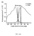
- FIG. 2(a) shows a plot of the a real density of cones and rods for the human eye.
- the cones are heavily concentrated in a solid angle of less than 5 degrees.
- the eyeball moves in its socket at angles up to about 25 degrees from central fixation in saccadic movements.
- the natural physiological response is to initiate head movement.
- Saccadic movements allow the region of maximum photoreceptor sensitivity, the fovea, which subtends a small solid angle, to cover a wider range of angles without head movement.
- the foveal response and saccadic motion are then combined with the geometrical optics of a spectacle lens to produce S( ⁇ , ⁇ ).
- S( ⁇ , ⁇ ) As can be seen in figure 2B, from each optical ray that enters the pupil there are corresponding locations and angles at both the retina and the surfaces of the ophthalmic lens.
- the angles with which light strikes the coated article and is subsequently imaged on the fovea over the range of saccadic eyeball motions is directly converted to the angular variation of S( ⁇ , ⁇ ).
- the visual response function S( ⁇ , ⁇ ) shown in FIG. 3 combines the human response functions for wavelength and angle appropriate to viewing through a spectacle lens.
- the particular form of S( ⁇ , ⁇ ) may vary in a manner consistent with the viewing conditions.
- the rod photoreceptors are primarily active in low light conditions, resulting in an angular sensitivity that is dramatically different than for photopic vision, as can be inferred from the rod photoreceptor density shown in FIG. 2.
- the chromatic (wavelength-dependent) response of the rods is also different, having a maximum at 507 nm and a full-width at half maximum of 100 nm as described more fully in Wyszecki, p. 258 FIG. 4.3.2.
- Another example for use of different S( ⁇ , ⁇ ) is obtained for humans with partial color blindness or retinal damage such as is caused by macular degeneration.
- the angular component of S( ⁇ , ⁇ ) also varies with the geometry of the optical viewing condition.
- the angular variation of S depends on the geometric relationship between the observer, the coated article, and the position of the illumination source, rather than on the observer's saccadic eye movements.
- the angular dependence of reflection from an automotive windshield will depend on its distance from the driver's head and its angle in the frame of the automobile.
- the coating materials, number of layers, and ordering of layers may be the same for two applications, say a windshield and a spectacle lens, the layer thicknesses computed for minimal Fa according to the invention may be different for each application.
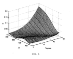
- FIG. 4 An example of the solution to the Fresnel equations using wavelengths between 390 and 710 nm and angles up to 60 degrees for a glass substrate coated with 72 nm of PrO 2 68 nm of TiO x , and 100 nm of MgF is shown in FIG. 4.
- This arrangement of layers and thicknesses is described as an anti-reflection (AR) coating in McLeod, op.cit., p. 110.
- the plot in FIG. 4 shows the average of s - and p - polarized reflectance, which is appropriate for human visual performance since human vision does not sense optical polarization. Changes to the substrate, the refractive properties of layers, or the order in which they are coated onto the substrate lead to complex but calculable changes in the reflectance R( ⁇ , ⁇ ,P).
- the design of an AR coating is based on perceived reflectance.
- F uncoated article or "F o "
- perceived reflectance of an AR coated substrate is sometimes referred to as "F”.
- the value of F depends on the wavelength-dependent refractive indices of the substrate and layer media, on the thickness of the layers, and also on the angular and wavelength dependent visual response as described above.
- equation 7 is solved for the absolute minimum value of F (denoted Fmin) for a given stack of coatings or layers on a substrate, for a given geometry of viewing conditions.
- F the absolute minimum value of F
- equation 7 is solved for a range of values close to, but not necessarily equal to, F min . That is, good results are obtained when the value of F is small, but not necessarily an absolute minimum.
- the value of F for the coated substrate is within 25% of F min , i.e., F ⁇ to 1.25 F min .
- equation 7 is solved for values of F within 20%, 15%, or even 10% of F min , i.e., F ⁇ 1.20 F min , F ⁇ 1.15 F min , or F ⁇ 1.10 F min .
- F min i.e., F ⁇ 1.20 F min , F ⁇ 1.15 F min , or F ⁇ 1.10 F min .
- the solution to F enables one to identify the combination of physical thicknesses of layers of anti-reflection coatings that satisfy the desired range or value of F.
- the perceived reflectance, F is computed for all combinations of layer thicknesses and the set of thicknesses for which F is minimized is selected. Beginning with the glass:PrO:TiO:MgF system described above, this calculation was performed and the minimum perceived reflectance F min , was calculated to be 104, which is 18% that of the uncoated article and a 35% reduction from that of the textbook coating. This absolute minimum value of perceived reflectance (shown in FIG. 6) for these materials corresponds to the following physical thicknesses: 100nm of Pr0, 25nm of TiO, and 87nm of MgF.
- equation 7 can be solved (for F, F min , 1.25F min , or any other desired value or range of F) using linear algebra and calculus.
- linear algebra software can be used as an alternative to manual computation.
- Non-limiting examples of such software include Mathematica (Wolfram Research, Champaign-Urbana, IL), Matlab (The MathWorks, Inc., Natick, MA), Macsyma (Macsyma Inc., Arlington, MA), and Maple (Waterloo Maple, Inc., Waterloo, Ontario, Canada).
- Mathematica Wood Research, Champaign-Urbana, IL
- Matlab The MathWorks, Inc., Natick, MA
- Macsyma Macsyma Inc., Arlington, MA
- Maple Waterloo Maple, Inc., Waterloo, Ontario, Canada.
- Computational analysis of F is also possible using spreadsheet software, for example Excel (Microsoft, Redmond, WA) and Lotus 1-2-3 (Lotus
- the value of F corresponding to thicknesses 42, 80 and 80nm, respectively, is 121, as is the value for a 40, 82, and 80nm system.
- F becomes 122.
- the value F is within 25% of F min .
- the thicknesses are set to 40, 80, and 78nm, the value of F rises to 136, which is 31% higher than F min .
- a further aspect of the present invention concerns constraints on the perceived color of light reflected from the coated article.
- this embodiment we consider the AR coatings summarized in Table I from the point of view of an observer looking at a person wearing the spectacle lens. Light from overhead lamps, windows, or other sources of illumination strike the surface of the lens and are reflected into the eye of an observer at an angle ( ⁇ ) as shown schematically in FIG. 7.
- the color of this reflection depends on the wavelength-dependent intensity of the illuminant (sunlight filtered by the window), the wavelength and angle dependent reflectance of the coated article (the coated spectacle lens), and the physiology of color vision as described, for example, in Wandell, Foundations of Vision, Sinauer Associates:Sunderland MA, 1995, or Wyszecki and Stiles op cit.
- the dominant wavelength which is defined as the wavelength at which a monochromatic stimulus produces the same perceived color, is found by tracing a line from the white point (diamond) to the periphery of the plot through the computed CIE color point.
- both the textbook coating at a viewing angle of 50 degrees and the minimal F min coating at 0 degrees have a dominant wavelength of about 480 nm, that is, blue-green.
- the dominant wavelength provides a qualitative label with which to compare various hues.
- FIG 9(a) shows the spectra of three standard illuminats: daylight at sea level, an incandescent tungsten lamp, and a fluorescent lamp.
- the perceived color, as quantified by the CIE chromaticity coordinates, is a function of both the angle and the illuminant.
- FIG. 10 shows the perceived color for sunlight reflected from each of the Examples 2-19 summarized in Table I at normal incidence.
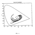
- Table I the angle between the illuminant, lens, and observer is increased, there is a shift in the perceived color as shown in FIG. 11, where the chromaticity coordinate trajectories are plotted in five degree intervals from 0 to 60 degrees.
- these calculated colors are used in connection with cosmetic or other color criteria to produce an article that has minimal perceived reflectance while maintaining a predefined color. For example, if one desires to minimize the appearance of the reflection one might match the hue to that of the wearer's skin color.
- color control one might elect the AR coating that has the smallest change in hue as it is tipped through a predetermined angular range under a predetermined source of illlumination. This range can be quantified by computing the length of the curves shown in figure 11 after the coordinates are transformed from the 1931 CIE color space to the 1976 CIE uniform (L*,u*,v*) color space.
- the empirically determined average values of S( ⁇ , ⁇ ) are used to determine the preferred response factor to be used in designing an AR coating.
- construction of individual profiles for individuals with peculiar constraints on S( ⁇ ), such as would occur, for example, in individuals that are blind in one eye or that suffer from macular degeneration, are also encompassed by the invention.
- the perceived reflectance, F is numerically evaluated for one or more layers on an optical substrate as a function of the thickness, composition, and order in which they are coated on the substrate.
- the composition and order may be constrained by other material issues such as adhesion, surface energy, chemical resistance, etc.
- the preferred thickness of the layer(s) in an AR coating brings the value of F to within 25% of its absolute minimum, subject to these constraints.
- the thickness of the layer(s) may also be constrained by the color perceived for light reflected from the article and into the eyes of an observer.
- This auxiliary optical constraint yields an AR coated article that is at once minimally reflective while having cosmetically desirable appearance.
- a second embodiment of an AR coated article according to the present invention is a computer monitor or video screen that has a glass surface.
- Anti-reflection coatings for these articles are desirable because overhead or window illumination causes reflected images that impair the visibility of the images projected onto the display screen.
- the photopic response, S( ⁇ ), for the human observer is as shown in FIG. 1.
- the angular component of S( ⁇ , ⁇ ) is substantially different than for the spectacle lens.
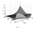
- Presuming overhead illumination in a typical workplace environment, and using simple geometry, a sample S( ⁇ , ⁇ ) is shown in FIG. 12.
- the perceived reflectance of the uncoated screen is 717, while that found for the textbook PrO:TiO:MgF coating is 258, or 36% of that for the uncoated display.
- the layer thicknesses that reduce F to 191, its minimal value (26.6% that of the uncoated display), are found to be 60 nm PrO, 80 nm TiO, and 120 nm MgF.
- a plot showing F min for this embodiment is presented in FIG. 13.
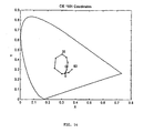
- the chromaticity coordinates for this AR coated display terminal are shown in FIG. 14. As before, a series of computations is undertaken and yields values within a desired percentage of the minimum value of F, I.e., 25%, while the hue of the reflected light is separately computed for relevant angles using the colorimetry formulae. After evaluating the chromaticity coordinates of each design in Table II, the cobmination of hue and minimally perceived reflectance can be selected based on cosmetic or visual function constraints. For example, if the video display background is a preset color it is desirable to make the reflected hue blend with this background color to further reduce the reflections' visual impacts.
- the invention provides unique articles of manufacture, characterized by low reflectance.
- the articles are transparent, for example, ophthalmic lenses, windows, windshields, television and computer screens, etc.
- Transparent articles have no absorption of light over the region of the spectrum sensed by the human visual system, that is between about 350 and about 750 nm. In some embodiments, however, the article may be translucent. Translucent articles transmit light at some visible wavelengths but absorb some or all of the light at one or more visible wavelengths.
- Nonlimiting examples of translucent articles include tinted and shaded sunglasses, stained-glass windows, and tinted windshields.
- a transparent, low reflection article comprises an optical substrate and one or more layers of AR material.
- the invention has been described in preferred and exemplary embodiments, but is not limited thereto. A variety of modifications, modes of operations and embodiments, all within the ability and skill of those skilled in the art, can be made without departing from the present invention.
- the AR coatings and methods of designing and applying them can be used on a variety of optical substrates in addition to ophthalmic lenses. Even large articles, like automotive windshields, can be given an AR coating if a suitably large reactor is built.
- Embodiments of the invention may include the features of the following enumerated paragraphs ("paras").
Landscapes
- Chemical & Material Sciences (AREA)
- Engineering & Computer Science (AREA)
- Chemical Kinetics & Catalysis (AREA)
- General Chemical & Material Sciences (AREA)
- Materials Engineering (AREA)
- Organic Chemistry (AREA)
- Life Sciences & Earth Sciences (AREA)
- Geochemistry & Mineralogy (AREA)
- Physics & Mathematics (AREA)
- Optics & Photonics (AREA)
- General Physics & Mathematics (AREA)
- Mechanical Engineering (AREA)
- Metallurgy (AREA)
- Laminated Bodies (AREA)
- Eyeglasses (AREA)
- Surface Treatment Of Optical Elements (AREA)
- Paints Or Removers (AREA)
- Surface Treatment Of Glass (AREA)
- Optical Filters (AREA)
- Treatments Of Macromolecular Shaped Articles (AREA)
- Optical Elements Other Than Lenses (AREA)
Applications Claiming Priority (3)
| Application Number | Priority Date | Filing Date | Title |
|---|---|---|---|
| US364748 | 1999-07-30 | ||
| US09/364,748 US6172812B1 (en) | 1997-01-27 | 1999-07-30 | Anti-reflection coatings and coated articles |
| EP00953693A EP1203244B1 (fr) | 1999-07-30 | 2000-07-27 | Méthode de fabrication d'un article traité antireflet |
Related Parent Applications (1)
| Application Number | Title | Priority Date | Filing Date |
|---|---|---|---|
| EP00953693A Division EP1203244B1 (fr) | 1999-07-30 | 2000-07-27 | Méthode de fabrication d'un article traité antireflet |
Publications (2)
| Publication Number | Publication Date |
|---|---|
| EP1557698A2 true EP1557698A2 (fr) | 2005-07-27 |
| EP1557698A3 EP1557698A3 (fr) | 2006-01-25 |
Family
ID=23435906
Family Applications (2)
| Application Number | Title | Priority Date | Filing Date |
|---|---|---|---|
| EP05075381A Withdrawn EP1557698A3 (fr) | 1999-07-30 | 2000-07-27 | Article à traitement anti-réflet |
| EP00953693A Expired - Lifetime EP1203244B1 (fr) | 1999-07-30 | 2000-07-27 | Méthode de fabrication d'un article traité antireflet |
Family Applications After (1)
| Application Number | Title | Priority Date | Filing Date |
|---|---|---|---|
| EP00953693A Expired - Lifetime EP1203244B1 (fr) | 1999-07-30 | 2000-07-27 | Méthode de fabrication d'un article traité antireflet |
Country Status (14)
| Country | Link |
|---|---|
| US (1) | US6172812B1 (fr) |
| EP (2) | EP1557698A3 (fr) |
| JP (1) | JP2003506735A (fr) |
| KR (1) | KR100749429B1 (fr) |
| CN (1) | CN1372646A (fr) |
| AT (1) | ATE296456T1 (fr) |
| AU (1) | AU781941B2 (fr) |
| BR (1) | BR0013299A (fr) |
| CA (1) | CA2380595C (fr) |
| DE (1) | DE60020374T2 (fr) |
| HK (1) | HK1047160A1 (fr) |
| IL (1) | IL147867A (fr) |
| MX (1) | MXPA02001074A (fr) |
| WO (1) | WO2001009647A1 (fr) |
Cited By (3)
| Publication number | Priority date | Publication date | Assignee | Title |
|---|---|---|---|---|
| WO2010025829A1 (fr) * | 2008-09-08 | 2010-03-11 | Carl Zeiss Vision Gmbh | Verre de lunettes avec revêtement antireflet de couleur neutre et procédé de fabrication associé |
| RU2684919C2 (ru) * | 2015-03-13 | 2019-04-16 | Рупп + Хубрах Оптик Гмбх | Оптическое изделие, содержащее просветляющее покрытие в видимой области, для условий низкой освещенности |
| EP3505998A4 (fr) * | 2017-09-29 | 2020-05-06 | Hoya Lens Thailand Ltd. | Verre de lunettes et lunettes |
Families Citing this family (29)
| Publication number | Priority date | Publication date | Assignee | Title |
|---|---|---|---|---|
| JP2001322833A (ja) * | 2000-05-09 | 2001-11-20 | Central Glass Co Ltd | 車両用低反射ガラス |
| DE60122837T2 (de) * | 2000-07-27 | 2007-09-06 | Asahi Glass Co., Ltd. | Mit Antireflexionsfilmen ausgestattetes Substrat und dessen Herstellungsverfahren |
| DE10100442A1 (de) * | 2001-01-08 | 2002-07-11 | Bayer Ag | Transparente Kunststoff-Formmasse |
| US6770321B2 (en) * | 2002-01-25 | 2004-08-03 | Afg Industries, Inc. | Method of making transparent articles utilizing protective layers for optical coatings |
| FR2841339B1 (fr) * | 2002-06-19 | 2004-09-10 | Centre Nat Rech Scient | Supports anti-reflechissants et supports amplificateurs de contraste pour la lumiere polarisee en reflexion |
| US6940651B2 (en) * | 2002-12-30 | 2005-09-06 | Eitan Zeira | Durable nano-structured optical surface |
| DE102004020245A1 (de) * | 2004-04-22 | 2005-12-22 | Schott Ag | Organisches, elektro-optisches Element mit erhöhter Auskoppeleffizienz |
| TWI245922B (en) * | 2004-09-02 | 2005-12-21 | Asia Optical Co Inc | Coating method for wet-coated thin film using an anti-reflective compound |
| JP4887612B2 (ja) * | 2004-10-20 | 2012-02-29 | 日油株式会社 | 減反射材及びそれを用いた電子画像表示装置 |
| US7354779B2 (en) * | 2006-03-10 | 2008-04-08 | International Business Machines Corporation | Topography compensated film application methods |
| US8186113B2 (en) * | 2007-07-09 | 2012-05-29 | Raytheon Canada Limited | Building window having a visible-light-reflective optical interference coating thereon |
| US9041745B2 (en) * | 2008-06-03 | 2015-05-26 | Samsung Display Co., Ltd. | Method of boosting a local dimming signal, boosting drive circuit for performing the method, and display apparatus having the boosting drive circuit |
| US8503840B2 (en) | 2010-08-23 | 2013-08-06 | Lockheed Martin Corporation | Optical-fiber array method and apparatus |
| CN102252997B (zh) * | 2011-04-18 | 2014-12-31 | 暨南大学 | 一种测定微球或介质折射率的方法及其应用 |
| EP2785662A2 (fr) * | 2011-11-30 | 2014-10-08 | Corning Incorporated | Procédé de fabrication d'articles en verre pourvus de revêtements optiques et faciles à nettoyer |
| US9957609B2 (en) | 2011-11-30 | 2018-05-01 | Corning Incorporated | Process for making of glass articles with optical and easy-to-clean coatings |
| JP6167488B2 (ja) * | 2012-08-30 | 2017-07-26 | 大日本印刷株式会社 | 反射防止膜 |
| US9366784B2 (en) | 2013-05-07 | 2016-06-14 | Corning Incorporated | Low-color scratch-resistant articles with a multilayer optical film |
| US9110230B2 (en) | 2013-05-07 | 2015-08-18 | Corning Incorporated | Scratch-resistant articles with retained optical properties |
| US9359261B2 (en) | 2013-05-07 | 2016-06-07 | Corning Incorporated | Low-color scratch-resistant articles with a multilayer optical film |
| US9703011B2 (en) | 2013-05-07 | 2017-07-11 | Corning Incorporated | Scratch-resistant articles with a gradient layer |
| US9684097B2 (en) | 2013-05-07 | 2017-06-20 | Corning Incorporated | Scratch-resistant articles with retained optical properties |
| JP6470274B2 (ja) * | 2013-07-05 | 2019-02-13 | エシロール アンテルナショナルEssilor International | 可視領域において非常に低い反射を有する反射防止被覆を含む光学物品 |
| US11267973B2 (en) * | 2014-05-12 | 2022-03-08 | Corning Incorporated | Durable anti-reflective articles |
| US9335444B2 (en) | 2014-05-12 | 2016-05-10 | Corning Incorporated | Durable and scratch-resistant anti-reflective articles |
| US9790593B2 (en) | 2014-08-01 | 2017-10-17 | Corning Incorporated | Scratch-resistant materials and articles including the same |
| EP3045940A1 (fr) * | 2014-12-31 | 2016-07-20 | Essilor International (Compagnie Generale D'optique) | Lentille ophthalmique ayant un traitement anti-reflets pour des conditions de faible luminance |
| CN107735697B (zh) | 2015-09-14 | 2020-10-30 | 康宁股份有限公司 | 减反射制品以及包含其的显示器装置 |
| EP3837223A1 (fr) | 2018-08-17 | 2021-06-23 | Corning Incorporated | Articles en un oxyde inorganique comportant des structures antiréfléchissantes durables et minces |
Citations (8)
| Publication number | Priority date | Publication date | Assignee | Title |
|---|---|---|---|---|
| EP0112418A1 (fr) * | 1982-12-22 | 1984-07-04 | International Business Machines Corporation | Revêtement antiréfléchissant pour écrans d'affichage |
| US5508091A (en) * | 1992-12-04 | 1996-04-16 | Photran Corporation | Transparent electrodes for liquid cells and liquid crystal displays |
| EP0803481A2 (fr) * | 1996-04-25 | 1997-10-29 | Ppg Industries, Inc. | Articles revêtus presentant des facteurs de transmission élevé et d'émission faible |
| US5717282A (en) * | 1995-02-20 | 1998-02-10 | U.S. Philips Corporation | Display device comprising a display screen having a light-absorbing coating |
| WO1998033077A2 (fr) * | 1997-01-27 | 1998-07-30 | Haaland Peter D | Revetements, procedes et appareil pour reduire la reflexion a partir de substrats optiques |
| US5852513A (en) * | 1997-05-14 | 1998-12-22 | Optical Coating Laboratory, Inc. | Television filter |
| WO1999021048A1 (fr) * | 1997-10-21 | 1999-04-29 | Sola International Holdings Ltd. | Verres enduits pour lunettes de soleil |
| EP0933654A2 (fr) * | 1997-12-31 | 1999-08-04 | The Boc Group, Inc. | Revêtements antireflets |
Family Cites Families (47)
| Publication number | Priority date | Publication date | Assignee | Title |
|---|---|---|---|---|
| US3356522A (en) | 1964-02-10 | 1967-12-05 | Mc Donnell Douglas Corp | Polycarbonate film containing an antireflection coating |
| JPS53306B2 (fr) | 1973-10-16 | 1978-01-07 | ||
| US3892490A (en) | 1974-03-06 | 1975-07-01 | Minolta Camera Kk | Monitoring system for coating a substrate |
| US4058638A (en) | 1974-12-19 | 1977-11-15 | Texas Instruments Incorporated | Method of optical thin film coating |
| NL7606630A (nl) | 1975-10-20 | 1977-04-22 | Nasa | Werkwijze om anti-reflectielagen op lenzen aan te brengen. |
| US4096315A (en) | 1976-12-15 | 1978-06-20 | The United States Of America As Represented By The Administrator Of The National Aeronautics And Space Administration | Process for producing a well-adhered durable optical coating on an optical plastic substrate |
| CH625054A5 (fr) | 1976-12-27 | 1981-08-31 | Balzers Hochvakuum | |
| US4166784A (en) | 1978-04-28 | 1979-09-04 | Applied Films Lab, Inc. | Feedback control for vacuum deposition apparatus |
| WO1980000504A1 (fr) | 1978-08-18 | 1980-03-20 | Nat Res Dev | Commande du depot de pellicule fine |
| GB2064987B (en) | 1979-11-14 | 1983-11-30 | Toray Industries | Process for producing transparent shaped article having enhanced anti-reflective effect |
| JPH0642003B2 (ja) | 1983-09-20 | 1994-06-01 | オリンパス光学工業株式会社 | 光学部品の反射防止膜とその形成方法 |
| JPS60163901A (ja) | 1984-02-04 | 1985-08-26 | Japan Synthetic Rubber Co Ltd | プラズマ重合処理方法 |
| DE3413019A1 (de) | 1984-04-06 | 1985-10-17 | Robert Bosch Gmbh, 7000 Stuttgart | Verfahren zum aufbringen einer duennen, transparenten schicht auf der oberflaeche optischer elemente |
| US4676646A (en) | 1985-10-15 | 1987-06-30 | Energy Conversion Devices, Inc. | Method and apparatus for controlling thickness of a layer of an optical data storage device by measuring an optical property of the layer |
| CH670318A5 (fr) | 1985-10-22 | 1989-05-31 | Satis Vacuum Ag | |
| US4837044A (en) | 1987-01-23 | 1989-06-06 | Itt Research Institute | Rugate optical filter systems |
| US5053244A (en) | 1987-02-21 | 1991-10-01 | Leybold Aktiengesellschaft | Process for depositing silicon oxide on a substrate |
| US4842941A (en) | 1987-04-06 | 1989-06-27 | General Electric Company | Method for forming abrasion-resistant polycarbonate articles, and articles of manufacture produced thereby |
| FR2614317B1 (fr) | 1987-04-22 | 1989-07-13 | Air Liquide | Procede de protection de substrat polymerique par depot par plasma de composes du type oxynitrure de silicium et dispositif pour sa mise en oeuvre. |
| US4815962A (en) | 1987-12-11 | 1989-03-28 | Polaroid Corporation | Process for coating synthetic optical substrates |
| US5225057A (en) | 1988-02-08 | 1993-07-06 | Optical Coating Laboratory, Inc. | Process for depositing optical films on both planar and non-planar substrates |
| US5181142A (en) | 1988-06-10 | 1993-01-19 | Asahi Kogaku Kogyo Kabushiki Kaisha | Plastic lens and method of forming an anti-reflecting layer on a plastic lens |
| US4906844A (en) | 1988-08-12 | 1990-03-06 | Rockwell International Corporation | Phase sensitive optical monitor for thin film deposition |
| US5264724A (en) | 1989-02-13 | 1993-11-23 | The University Of Arkansas | Silicon nitride for application as the gate dielectric in MOS devices |
| US5181141A (en) | 1989-03-31 | 1993-01-19 | Hoya Corporation | Anti-reflection optical element |
| US5246782A (en) | 1990-12-10 | 1993-09-21 | The Dow Chemical Company | Laminates of polymers having perfluorocyclobutane rings and polymers containing perfluorocyclobutane rings |
| US5009920A (en) | 1990-03-30 | 1991-04-23 | Honeywell Inc. | Method for applying optical interference coating |
| JPH04191701A (ja) | 1990-11-26 | 1992-07-10 | Akifumi Nishikawa | 反射防止光学材料およびその製造法 |
| US5171414A (en) | 1990-12-10 | 1992-12-15 | Ford Motor Company | Method of making transparent anti-reflective coating |
| US5225244A (en) | 1990-12-17 | 1993-07-06 | Allied-Signal Inc. | Polymeric anti-reflection coatings and coated articles |
| US5178955A (en) | 1990-12-17 | 1993-01-12 | Allied-Signal Inc. | Polymeric anti-reflection coatings and coated articles |
| FR2680583B1 (fr) | 1991-08-22 | 1993-10-08 | Commissariat A Energie Atomique | Materiau presentant des proprietes antireflet, hydrophobes et de resistance a l'abrasion et procede de depot d'une couche antireflet, hydrophobe et resistante a l'abrasion sur un substrat. |
| JPH0597478A (ja) | 1991-10-04 | 1993-04-20 | Nippon Sheet Glass Co Ltd | 撥水性ガラス物品およびその製造方法 |
| WO1994002832A1 (fr) | 1992-07-15 | 1994-02-03 | On-Line Technologies, Inc. | Procede et appareil de surveillance du traitement d'une couche |
| WO1994019709A1 (fr) | 1993-02-19 | 1994-09-01 | Photran Corporation | Revetement antireflet attenuant la lumiere comprenant des couches electroconductrices |
| US5443941A (en) | 1993-03-01 | 1995-08-22 | National Semiconductor Corporation | Plasma polymer antireflective coating |
| JP3770625B2 (ja) | 1993-03-12 | 2006-04-26 | 旭硝子株式会社 | 反射防止層を有する光学物品 |
| US5354575A (en) | 1993-04-16 | 1994-10-11 | University Of Maryland | Ellipsometric approach to anti-reflection coatings of semiconductor laser amplifiers |
| US5911856A (en) | 1993-09-03 | 1999-06-15 | Canon Kabushiki Kaisha | Method for forming thin film |
| DE4338040C2 (de) | 1993-11-08 | 1997-01-30 | Leybold Ag | Vorrichtung zum Beschichten von Brillengläsern im Vakuum und Betriebsverfahren hierfür |
| US5494697A (en) | 1993-11-15 | 1996-02-27 | At&T Corp. | Process for fabricating a device using an ellipsometric technique |
| DE4407909C3 (de) | 1994-03-09 | 2003-05-15 | Unaxis Deutschland Holding | Verfahren und Vorrichtung zum kontinuierlichen oder quasi-kontinuierlichen Beschichten von Brillengläsern |
| US5425964A (en) | 1994-07-22 | 1995-06-20 | Rockwell International Corporation | Deposition of multiple layer thin films using a broadband spectral monitor |
| US5580606A (en) | 1995-10-06 | 1996-12-03 | Singapore Institute Of Standards Etc. | Method for forming interference anti-reflective coatings by plasma surface modification |
| US5772861A (en) | 1995-10-16 | 1998-06-30 | Viratec Thin Films, Inc. | System for evaluating thin film coatings |
| US5728456A (en) | 1996-02-01 | 1998-03-17 | Optical Coating Laboratory, Inc. | Methods and apparatus for providing an absorbing, broad band, low brightness, antireflection coating |
| US5789040A (en) | 1997-05-21 | 1998-08-04 | Optical Coating Laboratory, Inc. | Methods and apparatus for simultaneous multi-sided coating of optical thin film designs using dual-frequency plasma-enhanced chemical vapor deposition |
-
1999
- 1999-07-30 US US09/364,748 patent/US6172812B1/en not_active Expired - Lifetime
-
2000
- 2000-07-27 AT AT00953693T patent/ATE296456T1/de not_active IP Right Cessation
- 2000-07-27 WO PCT/US2000/020410 patent/WO2001009647A1/fr active IP Right Grant
- 2000-07-27 EP EP05075381A patent/EP1557698A3/fr not_active Withdrawn
- 2000-07-27 BR BR0013299-3A patent/BR0013299A/pt not_active IP Right Cessation
- 2000-07-27 DE DE60020374T patent/DE60020374T2/de not_active Expired - Fee Related
- 2000-07-27 KR KR1020027001344A patent/KR100749429B1/ko not_active IP Right Cessation
- 2000-07-27 JP JP2001514604A patent/JP2003506735A/ja active Pending
- 2000-07-27 CN CN00812343A patent/CN1372646A/zh active Pending
- 2000-07-27 IL IL14786700A patent/IL147867A/xx not_active IP Right Cessation
- 2000-07-27 EP EP00953693A patent/EP1203244B1/fr not_active Expired - Lifetime
- 2000-07-27 AU AU66097/00A patent/AU781941B2/en not_active Ceased
- 2000-07-27 CA CA002380595A patent/CA2380595C/fr not_active Expired - Fee Related
- 2000-07-27 MX MXPA02001074A patent/MXPA02001074A/es not_active Application Discontinuation
-
2002
- 2002-11-08 HK HK02108144A patent/HK1047160A1/xx not_active IP Right Cessation
Patent Citations (8)
| Publication number | Priority date | Publication date | Assignee | Title |
|---|---|---|---|---|
| EP0112418A1 (fr) * | 1982-12-22 | 1984-07-04 | International Business Machines Corporation | Revêtement antiréfléchissant pour écrans d'affichage |
| US5508091A (en) * | 1992-12-04 | 1996-04-16 | Photran Corporation | Transparent electrodes for liquid cells and liquid crystal displays |
| US5717282A (en) * | 1995-02-20 | 1998-02-10 | U.S. Philips Corporation | Display device comprising a display screen having a light-absorbing coating |
| EP0803481A2 (fr) * | 1996-04-25 | 1997-10-29 | Ppg Industries, Inc. | Articles revêtus presentant des facteurs de transmission élevé et d'émission faible |
| WO1998033077A2 (fr) * | 1997-01-27 | 1998-07-30 | Haaland Peter D | Revetements, procedes et appareil pour reduire la reflexion a partir de substrats optiques |
| US5852513A (en) * | 1997-05-14 | 1998-12-22 | Optical Coating Laboratory, Inc. | Television filter |
| WO1999021048A1 (fr) * | 1997-10-21 | 1999-04-29 | Sola International Holdings Ltd. | Verres enduits pour lunettes de soleil |
| EP0933654A2 (fr) * | 1997-12-31 | 1999-08-04 | The Boc Group, Inc. | Revêtements antireflets |
Non-Patent Citations (1)
| Title |
|---|
| LAIRD R E ET AL: "Durable conductive anti-reflection coatings for glass and plastic substrates" ANNUAL TECHNICAL CONFERENCE PROCEEDINGS SOCIETY OF VACUUM COATERS, ALBUQUERQUE, NM, US, 5 May 1996 (1996-05-05), pages 361-365, XP002124390 * |
Cited By (5)
| Publication number | Priority date | Publication date | Assignee | Title |
|---|---|---|---|---|
| WO2010025829A1 (fr) * | 2008-09-08 | 2010-03-11 | Carl Zeiss Vision Gmbh | Verre de lunettes avec revêtement antireflet de couleur neutre et procédé de fabrication associé |
| US8425035B2 (en) | 2008-09-08 | 2013-04-23 | Carl Zeiss Vision Gmbh | Spectacle lens with color-neutral anti-reflection coating and method of making the same |
| RU2684919C2 (ru) * | 2015-03-13 | 2019-04-16 | Рупп + Хубрах Оптик Гмбх | Оптическое изделие, содержащее просветляющее покрытие в видимой области, для условий низкой освещенности |
| EP3505998A4 (fr) * | 2017-09-29 | 2020-05-06 | Hoya Lens Thailand Ltd. | Verre de lunettes et lunettes |
| US11137623B2 (en) | 2017-09-29 | 2021-10-05 | Hoya Lens Thailand Ltd. | Spectacle lens and spectacles |
Also Published As
| Publication number | Publication date |
|---|---|
| CN1372646A (zh) | 2002-10-02 |
| KR100749429B1 (ko) | 2007-08-14 |
| AU6609700A (en) | 2001-02-19 |
| ATE296456T1 (de) | 2005-06-15 |
| IL147867A0 (en) | 2002-08-14 |
| WO2001009647A1 (fr) | 2001-02-08 |
| HK1047160A1 (en) | 2003-02-07 |
| US6172812B1 (en) | 2001-01-09 |
| JP2003506735A (ja) | 2003-02-18 |
| DE60020374D1 (de) | 2005-06-30 |
| MXPA02001074A (es) | 2003-10-14 |
| EP1203244A1 (fr) | 2002-05-08 |
| AU781941B2 (en) | 2005-06-23 |
| EP1557698A3 (fr) | 2006-01-25 |
| EP1203244B1 (fr) | 2005-05-25 |
| BR0013299A (pt) | 2002-04-02 |
| IL147867A (en) | 2005-11-20 |
| DE60020374T2 (de) | 2006-02-02 |
| CA2380595A1 (fr) | 2001-02-08 |
| KR20020044551A (ko) | 2002-06-15 |
| CA2380595C (fr) | 2007-11-06 |
Similar Documents
| Publication | Publication Date | Title |
|---|---|---|
| EP1203244B1 (fr) | Méthode de fabrication d'un article traité antireflet | |
| EP0772572B1 (fr) | Revetement absorbant la lumiere et a proprietes antireflets pour lunettes de soleil | |
| US7736742B2 (en) | Optical article covered with a visible-absorbing, multi-layer anti-reflective coating, and production method thereof | |
| JP7145848B2 (ja) | マルチアングル効率を有する反射防止被膜を含む光学レンズ | |
| JP2019049712A (ja) | 眼用レンズ | |
| CN109844573A (zh) | 在近红外区和蓝光区具有高反射的光学制品 | |
| CN109073785A (zh) | 包括在近红外区(nir)中具有高反射的减反射涂层的光学制品 | |
| US11561416B2 (en) | Ophthalmic tinted glass | |
| WO2000033111A1 (fr) | Lentille traitee a facteur de reflexion sensiblement equilibre | |
| US6794066B2 (en) | Optical element with mirror coating and method for forming said coating | |
| CN107111000A (zh) | 包括在紫外区域具有高反射率的干涉涂层的光学物品 | |
| JP2022509087A (ja) | 耐摩耗性を改善するためのフィルタリング干渉コーティング及び多層系を有する光学レンズ | |
| CN113467101A (zh) | 一种双渐进镜片及其制备方法 | |
| EP4102265A1 (fr) | Lentille optique comportant un revêtement antireflet réfléchissant la lumière bleue nocive | |
| EP4109141A1 (fr) | Lentille optique comportant un revêtement interférentiel absorbant la lumière | |
| EP4102264A1 (fr) | Lentille optique dotée d'un revêtement antireflet réfléchissant la lumière bleue nocive et le rayonnement infrarouge proche | |
| AU766852B2 (en) | Coated lens exhibiting substantially balanced reflectance | |
| JP2024518649A (ja) | 非対称ミラーを有する光学レンズ | |
| WO2022258793A1 (fr) | Lentille optique ayant un revêtement antireflet réfléchissant la lumière bleue |
Legal Events
| Date | Code | Title | Description |
|---|---|---|---|
| PUAI | Public reference made under article 153(3) epc to a published international application that has entered the european phase |
Free format text: ORIGINAL CODE: 0009012 |
|
| AC | Divisional application: reference to earlier application |
Ref document number: 1203244 Country of ref document: EP Kind code of ref document: P |
|
| AK | Designated contracting states |
Kind code of ref document: A2 Designated state(s): AT BE CH CY DE DK ES FI FR GB GR IE IT LI LU MC NL PT SE |
|
| PUAL | Search report despatched |
Free format text: ORIGINAL CODE: 0009013 |
|
| AK | Designated contracting states |
Kind code of ref document: A3 Designated state(s): AT BE CH CY DE DK ES FI FR GB GR IE IT LI LU MC NL PT SE |
|
| REG | Reference to a national code |
Ref country code: HK Ref legal event code: DE Ref document number: 1077641 Country of ref document: HK |
|
| 17P | Request for examination filed |
Effective date: 20060713 |
|
| 17Q | First examination report despatched |
Effective date: 20060829 |
|
| AKX | Designation fees paid |
Designated state(s): AT BE CH CY DE DK ES FI FR GB GR IE IT LI LU MC NL PT SE |
|
| STAA | Information on the status of an ep patent application or granted ep patent |
Free format text: STATUS: THE APPLICATION IS DEEMED TO BE WITHDRAWN |
|
| 18D | Application deemed to be withdrawn |
Effective date: 20090203 |
|
| REG | Reference to a national code |
Ref country code: HK Ref legal event code: WD Ref document number: 1077641 Country of ref document: HK |