EP1557580A2 - Système de vanne pour système de commande d'embrayage de véhicule automobile - Google Patents
Système de vanne pour système de commande d'embrayage de véhicule automobile Download PDFInfo
- Publication number
- EP1557580A2 EP1557580A2 EP05000291A EP05000291A EP1557580A2 EP 1557580 A2 EP1557580 A2 EP 1557580A2 EP 05000291 A EP05000291 A EP 05000291A EP 05000291 A EP05000291 A EP 05000291A EP 1557580 A2 EP1557580 A2 EP 1557580A2
- Authority
- EP
- European Patent Office
- Prior art keywords
- pressure
- valve
- clutch
- actuator
- flow
- Prior art date
- Legal status (The legal status is an assumption and is not a legal conclusion. Google has not performed a legal analysis and makes no representation as to the accuracy of the status listed.)
- Granted
Links
Images
Classifications
-
- F—MECHANICAL ENGINEERING; LIGHTING; HEATING; WEAPONS; BLASTING
- F16—ENGINEERING ELEMENTS AND UNITS; GENERAL MEASURES FOR PRODUCING AND MAINTAINING EFFECTIVE FUNCTIONING OF MACHINES OR INSTALLATIONS; THERMAL INSULATION IN GENERAL
- F16D—COUPLINGS FOR TRANSMITTING ROTATION; CLUTCHES; BRAKES
- F16D23/00—Details of mechanically-actuated clutches not specific for one distinct type
- F16D23/12—Mechanical clutch-actuating mechanisms arranged outside the clutch as such
-
- F—MECHANICAL ENGINEERING; LIGHTING; HEATING; WEAPONS; BLASTING
- F16—ENGINEERING ELEMENTS AND UNITS; GENERAL MEASURES FOR PRODUCING AND MAINTAINING EFFECTIVE FUNCTIONING OF MACHINES OR INSTALLATIONS; THERMAL INSULATION IN GENERAL
- F16D—COUPLINGS FOR TRANSMITTING ROTATION; CLUTCHES; BRAKES
- F16D48/00—External control of clutches
- F16D48/02—Control by fluid pressure
- F16D2048/0221—Valves for clutch control systems; Details thereof
-
- F—MECHANICAL ENGINEERING; LIGHTING; HEATING; WEAPONS; BLASTING
- F16—ENGINEERING ELEMENTS AND UNITS; GENERAL MEASURES FOR PRODUCING AND MAINTAINING EFFECTIVE FUNCTIONING OF MACHINES OR INSTALLATIONS; THERMAL INSULATION IN GENERAL
- F16D—COUPLINGS FOR TRANSMITTING ROTATION; CLUTCHES; BRAKES
- F16D48/00—External control of clutches
- F16D48/02—Control by fluid pressure
- F16D2048/0257—Hydraulic circuit layouts, i.e. details of hydraulic circuit elements or the arrangement thereof
- F16D2048/0266—Actively controlled valves between pressure source and actuation cylinder
-
- F—MECHANICAL ENGINEERING; LIGHTING; HEATING; WEAPONS; BLASTING
- F16—ENGINEERING ELEMENTS AND UNITS; GENERAL MEASURES FOR PRODUCING AND MAINTAINING EFFECTIVE FUNCTIONING OF MACHINES OR INSTALLATIONS; THERMAL INSULATION IN GENERAL
- F16D—COUPLINGS FOR TRANSMITTING ROTATION; CLUTCHES; BRAKES
- F16D2500/00—External control of clutches by electric or electronic means
- F16D2500/10—System to be controlled
- F16D2500/102—Actuator
- F16D2500/1026—Hydraulic
-
- F—MECHANICAL ENGINEERING; LIGHTING; HEATING; WEAPONS; BLASTING
- F16—ENGINEERING ELEMENTS AND UNITS; GENERAL MEASURES FOR PRODUCING AND MAINTAINING EFFECTIVE FUNCTIONING OF MACHINES OR INSTALLATIONS; THERMAL INSULATION IN GENERAL
- F16D—COUPLINGS FOR TRANSMITTING ROTATION; CLUTCHES; BRAKES
- F16D2500/00—External control of clutches by electric or electronic means
- F16D2500/30—Signal inputs
- F16D2500/302—Signal inputs from the actuator
- F16D2500/3023—Force
-
- F—MECHANICAL ENGINEERING; LIGHTING; HEATING; WEAPONS; BLASTING
- F16—ENGINEERING ELEMENTS AND UNITS; GENERAL MEASURES FOR PRODUCING AND MAINTAINING EFFECTIVE FUNCTIONING OF MACHINES OR INSTALLATIONS; THERMAL INSULATION IN GENERAL
- F16D—COUPLINGS FOR TRANSMITTING ROTATION; CLUTCHES; BRAKES
- F16D2500/00—External control of clutches by electric or electronic means
- F16D2500/30—Signal inputs
- F16D2500/302—Signal inputs from the actuator
- F16D2500/3024—Pressure
-
- F—MECHANICAL ENGINEERING; LIGHTING; HEATING; WEAPONS; BLASTING
- F16—ENGINEERING ELEMENTS AND UNITS; GENERAL MEASURES FOR PRODUCING AND MAINTAINING EFFECTIVE FUNCTIONING OF MACHINES OR INSTALLATIONS; THERMAL INSULATION IN GENERAL
- F16D—COUPLINGS FOR TRANSMITTING ROTATION; CLUTCHES; BRAKES
- F16D2500/00—External control of clutches by electric or electronic means
- F16D2500/70—Details about the implementation of the control system
- F16D2500/702—Look-up tables
- F16D2500/70205—Clutch actuator
- F16D2500/70217—Pressure
-
- F—MECHANICAL ENGINEERING; LIGHTING; HEATING; WEAPONS; BLASTING
- F16—ENGINEERING ELEMENTS AND UNITS; GENERAL MEASURES FOR PRODUCING AND MAINTAINING EFFECTIVE FUNCTIONING OF MACHINES OR INSTALLATIONS; THERMAL INSULATION IN GENERAL
- F16D—COUPLINGS FOR TRANSMITTING ROTATION; CLUTCHES; BRAKES
- F16D2500/00—External control of clutches by electric or electronic means
- F16D2500/70—Details about the implementation of the control system
- F16D2500/702—Look-up tables
- F16D2500/70205—Clutch actuator
- F16D2500/70235—Displacement
-
- F—MECHANICAL ENGINEERING; LIGHTING; HEATING; WEAPONS; BLASTING
- F16—ENGINEERING ELEMENTS AND UNITS; GENERAL MEASURES FOR PRODUCING AND MAINTAINING EFFECTIVE FUNCTIONING OF MACHINES OR INSTALLATIONS; THERMAL INSULATION IN GENERAL
- F16D—COUPLINGS FOR TRANSMITTING ROTATION; CLUTCHES; BRAKES
- F16D2500/00—External control of clutches by electric or electronic means
- F16D2500/70—Details about the implementation of the control system
- F16D2500/704—Output parameters from the control unit; Target parameters to be controlled
- F16D2500/70402—Actuator parameters
- F16D2500/70406—Pressure
Definitions
- the invention relates to a valve system for controlling a clutch or a Gear actuator of a motor vehicle, in particular of a dry clutch, with at least one actuator for actuating the clutch, vzw. to the Opening and / or closing the clutch, or to operate the gear selector and at least one tank for providing a hydraulic medium.
- the invention further relates to a method for controlling at least one Clutch or a gear selector of a motor vehicle, in particular of a Dry clutch, wherein at least one actuator for actuating the clutch or is driven to actuate the gear selector and wherein by means of a Tanks a hydraulic medium is provided, and wherein the clutch pressure or the Ganstellerdruck on the adjustment of the clutch or the Gear actuator varies and the tank pressure is substantially constant.
- pressure controls for controlling in particular from dry clutches corresponding "pressure controls" known.
- Pressure control valves or pressure switching valves in use Pressure regulators keep the pressure independent of the size of a higher form or Supply pressure constant, with pressure switching valves when reaching a certain set pressure a current path for another workflow release.
- the forces can be adjusted via the pressure control valves be that the insertion of a gear in the transmission as gently as possible for the Synchronizing rings of a switching device takes place.
- the pressure of pressure control valves via a set screw with lock nut or alternatively via an electrical and / or electronic Control can be influenced individually.
- a displacement control of the clutches is used, wherein the actuator usually moved by a defined amount and thus - at correspondingly stiff components - a relatively well reproducible change adjusts the clutch capacity.
- the flow valves regulate via a throttle effect the speed of movement of the flow medium / hydraulic medium within the hydraulic circuit, thereby enabling one Switching the clutches.
- the invention is therefore based on the object that the aforementioned valve system or the known method for controlling clutches or of Gear actuators to design and develop such that tax and / or Control problems, in particular caused by force hysteresis in almost Any operating situation can be avoided to wear the clutch as well as the transmission, in particular also to reduce the synchronizer rings and thereby extending their service life and subsequent maintenance costs to lower.
- valve system by at least one pressure regulating valve and at least one flow valve in Series connection are arranged in front of the actuator.
- the task for the method is now solved by combining at least one pressure control valve and at least one flow valve in series, the pressure control valve and / or the flow valve in such a way be controlled that the currently applied to the flow valve supply pressure depending on the change over the adjustment clutch pressure or gear actuator pressure is set.
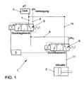
- Fig. 1 is a valve system 1 for controlling a coupling, not shown, in particular of dry clutches of a motor vehicle or to Control of a gear selector of a transmission, not shown, shown.
- the Valve system 1 has at least one actuator 2 for controlling the clutch or the gear selector and a tank 3 for providing a hydraulic medium on.
- a control device 4 with at least one tax technical Connection to the pressure control valve 5 and at least one tax technical Connection to the flow valve 6 is provided.
- the control device 4 is for Evaluation of various parameters formed. A variety of parameters are determinable for the ideal switching of dry clutches or gear actuators, Preferably, the control device 4 processes the engine speed, the gear ratio, the accelerator pedal position, the engine torque, the activities the brake, the transmission temperatures, the pressures or pressure differences etc. via appropriate sensors of the control device 4, the individual Parameter values supplied.
- the pressure regulating valve 5 has at least one first discharge line 7 to the tank 3 and, always to a corresponding supply pressure pV available, a first pressure line 8 to the pressure supply on. There is another connection to the flow valve 6 through a second pressure line 9 is provided. Through a connection of the pressure regulating valve 5 with the flow valve 6 is always the optimized required current Pressure at the flow valve 6 for the respective situation-dependent switching operation ensured or in particular by the control device 4 adjustable.
- the flow valve 6 is connected via the second pressure line 9 with the pressure control valve 5 connected. Furthermore, a second discharge capacity 10 to the tank 3 and a third pressure line 11 to the actuator 2.
- the actuator. 2 operated directly and / or indirectly the clutch or a gear plate of Motor vehicle, preferably via the corresponding displacement of here in 1 in the actuator 2 shown piston.
- the pressure regulating valve 5 is arranged in series connection in front of the flow valve 6.
- an arrangement of the flow valve 6 in series connection in front of the pressure regulating valve 5 is also conceivable.
- What is decisive is the combination of both valve characteristics in series connection or even taking account of the control device 4 for ideal tuning. Due to this fact, the pressure control valve 5 can provide on the second pressure line 9 of the flow valve 6 a current supply pressure pV (S) adapted to the operating situation and thus optimize the switching operation or the activation of the actuator 2.
- the pressure control valve 5 in the leading to the flow valve 6 second pressure line 9 a the respective operating situation adapted specific supply pressure pV (S) ready.
- the pressure control valve 5 controls and / or regulates the existing in the second pressure line 9 supply pressure pV (S) such that this currently at the flow valve 6 applied supply pressure pV (S) as a function of changing over the adjustment s clutch pressure pK (S) or changing gear actuator pressure is set.
- the pressure control valve 5 has vzw. an aperture over which the supply pressure pV (S) present in the second pressure line 9 can be correspondingly adjusted.
- the supply pressure pV (S) applied to the flow valve 6 is adjusted so that the quotient of the differential pressures, namely the difference between the current supply pressure pV (s) and the current clutch pressure pK (S) and from the difference of the current clutch pressure pK (S) or the gear actuator pressure and the tank pressure pT is substantially constant over the adjustment path s substantially.
- the quotient of the differential pressures namely the difference between the current supply pressure pV (s) and the current clutch pressure pK (S) and from the difference of the current clutch pressure pK (S) or the gear actuator pressure and the tank pressure pT is substantially constant over the adjustment path s substantially.
- Fig. 1 shows - as already mentioned - the valve system 1.
- this valve system 1 can now be driven corresponding clutches of a motor vehicle become.
- a corresponding gear actuator of a transmission of a motor vehicle to control accordingly. This depends on the particular application. It is crucial that with the help of the actuator 2 shown here, with the valve system 1 is activated or actuated, corresponding couplings or gear selector can then be operated.
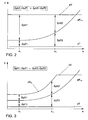
- FIGS. 2 and 3 show the supply pressure pV, the clutch pressure pK (S) , the tank pressure pT and the specifically set supply pressure pV (S) . It can be clearly seen that, in particular, the clutch pressure pK (S) changes as a function of the adjustment path s. As FIG. 2 shows, here the supply pressure pV is essentially constant. The same applies to the tank pressure pT. This is different in comparison to FIG. 3, which will be explained below.
- Fig. 2 are - as known in the art - the differential pressures occurring with respect to the closing and opening direction of a flow valve 6 schematically, without a pressure control valve 5 is connected in series, shown.
- the different differential pressures between the respective switching operations are, for example, the self-adjusting Pressure differences ⁇ pV1, ⁇ pT1, ⁇ pV2 and ⁇ pT2 are indicated by arrows. It is clearly seen that the quotient of the differential pressures, namely ⁇ pV1 / ⁇ pT1> ⁇ pV2 / ⁇ pT2, ie the quotients from the differential pressures are different.
- Fig. 3 the differential pressures in the closing and opening direction of the flow valve 6 with pressure precontrol or tracking by means of the pressure control valve 5 are shown schematically.
- the differential pressures ⁇ pV1, ⁇ pT1, ⁇ pV2, ⁇ pT2 that arise are also identified by corresponding arrows for different adjustment points S 1 and S 2 .
- the control device 4 controls and regulates Pressure control valve 5 and the flow valve 6. Additional parameters such as Engine speed, the transmission input position, the accelerator pedal position, the engine torque, the activities of the brake, the transmission temperatures and others Parameters can be taken into account and processed by the control device 4 become.
- the control device 4 is vzw. as electrical / electronic control device 4 formed, vzw. a corresponding microprocessor.
- the control device 4 is capable of existing in the third pressure line 11 to measure the actual clutch pressure pK (s) or with the help of the pressure control valve 5 and the flow valve 6, both vzw. corresponding apertures have to adjust accordingly. Furthermore, the volume flow by the flow valve 6 by the control device 4 influenced accordingly. Also conceivable is a corresponding change in the volume flow by the control of the flow valve 6 by the control device 4, in order to optimally adjust corresponding pressure differences.
- the actuator 2 is now driven accordingly to actuate the clutch or the gear actuator.
- a hydraulic medium is provided by means of a tank 3, wherein the clutch pressure pK (S) varies over the adjustment path s of the clutch or the gear actuator pressure and the tank pressure pT is substantially constant, as shown in FIGS. 2 and 3.
- the disadvantages described above are avoided.
- a "safety function” is realized.
- the flow valve 6 is no longer controllable and is in a second pressure line 9 with the third pressure line 11 connecting position, for example.
- the help Pressure control valve 5 By pollution or eg.
- the specific supply pressure pV (S) degraded.
- the actuator 2 can be relieved without the main pressure or supply pressure pV must be switched off.
- the specific supply pressure pV (S) can now be partially lowered or completely lowered without the supply pressure pV having to be modified.
- the system With actively closing couplings, the system can be transferred to the safe state "clutch open" without affecting other subfunctions.
- the system could be driven as a pure pressure control with appropriate design of the clutch force characteristic (eg: monotonically increasing). Especially in systems with only one clutch, this would allow emergency operation.
Landscapes
- Engineering & Computer Science (AREA)
- General Engineering & Computer Science (AREA)
- Mechanical Engineering (AREA)
- Physics & Mathematics (AREA)
- Fluid Mechanics (AREA)
- Hydraulic Clutches, Magnetic Clutches, Fluid Clutches, And Fluid Joints (AREA)
Applications Claiming Priority (2)
| Application Number | Priority Date | Filing Date | Title |
|---|---|---|---|
| DE102004001753A DE102004001753A1 (de) | 2004-01-12 | 2004-01-12 | Ventilsystem bzw. Verfahren zur Steuerung einer Kupplung oder eines Gangstellers eines Kraftfahrzeuges |
| DE102004001753 | 2004-01-12 |
Publications (3)
| Publication Number | Publication Date |
|---|---|
| EP1557580A2 true EP1557580A2 (fr) | 2005-07-27 |
| EP1557580A3 EP1557580A3 (fr) | 2009-10-07 |
| EP1557580B1 EP1557580B1 (fr) | 2012-01-04 |
Family
ID=34625712
Family Applications (1)
| Application Number | Title | Priority Date | Filing Date |
|---|---|---|---|
| EP05000291A Not-in-force EP1557580B1 (fr) | 2004-01-12 | 2005-01-07 | Procedé de commande d'embrayage de véhicule automobile |
Country Status (3)
| Country | Link |
|---|---|
| EP (1) | EP1557580B1 (fr) |
| AT (1) | ATE540236T1 (fr) |
| DE (1) | DE102004001753A1 (fr) |
Cited By (1)
| Publication number | Priority date | Publication date | Assignee | Title |
|---|---|---|---|---|
| DE102006050300A1 (de) * | 2006-10-23 | 2008-04-30 | Ortlinghaus-Werke Gmbh | Druckmittelbetätigte Schaltung |
Families Citing this family (11)
| Publication number | Priority date | Publication date | Assignee | Title |
|---|---|---|---|---|
| DE102005006431B4 (de) * | 2005-02-12 | 2014-10-09 | Volkswagen Ag | Ventilsystem bzw. Verfahren zur Steuerung einer Kupplung oder eines Gangstellers eines Kraftfahrzeuges |
| DE102006018683A1 (de) * | 2006-04-21 | 2007-10-25 | Dr.Ing.H.C. F. Porsche Ag | Verfahren und Vorrichtung zum Befüllen eines Gehäuses mit einer hydraulischen Flüssigkeit |
| US8475336B2 (en) | 2009-07-30 | 2013-07-02 | GM Global Technology Operations LLC | Hydraulic control system for a dual clutch transmission |
| US8613681B2 (en) | 2009-11-19 | 2013-12-24 | GM Global Technology Operations LLC | Transmission hydraulic control system having clutch compensator feed override |
| US8413437B2 (en) | 2009-12-08 | 2013-04-09 | GM Global Technology Operations LLC | Transmission hydraulic control system having independently controlled stator cooling flow |
| US8266986B2 (en) * | 2010-01-19 | 2012-09-18 | GM Global Technology Operations LLC | Transmission hydraulic control system having a dual element pump |
| US8402993B2 (en) | 2010-05-10 | 2013-03-26 | GM Global Technology Operations LLC | Hydraulic fluid cooling system for a dual clutch automatic transmission |
| US8844392B2 (en) | 2010-06-09 | 2014-09-30 | Gm Global Technology Operations, Llc | Electro-hydraulic and electro-mechanical control system for a dual clutch transmission |
| US8942901B2 (en) | 2010-12-09 | 2015-01-27 | Gm Global Technology Operations, Llc | Method of controlling a hydraulic control system for a dual clutch transmission |
| US8915076B2 (en) | 2011-01-12 | 2014-12-23 | Gm Global Technology Operations, Llc | Transmission hydraulic control system having flow augmentation |
| US8967351B2 (en) | 2012-08-14 | 2015-03-03 | Gm Global Technology Operations, Llc | Transmission clutch piston compensator feed circuit |
Family Cites Families (9)
| Publication number | Priority date | Publication date | Assignee | Title |
|---|---|---|---|---|
| GB789285A (en) * | 1956-06-27 | 1958-01-15 | Gen Motors Corp | Improvements relating to power transmission mechanisms |
| DE1284184B (de) * | 1964-09-11 | 1968-11-28 | Hengstler Hydraulik | Steuergeraet fuer das wechselweise Beaufschlagen zweier hydraulisch zu betaetigenderReibungskupplungen |
| DE2141564A1 (de) * | 1971-08-19 | 1973-02-22 | Zahnradfabrik Friedrichshafen | Teilschaltkreis in einer hydraulischen motor- und kupplungssteuerung fuer kraftfahrzeugantriebe |
| US4924983A (en) * | 1987-12-10 | 1990-05-15 | Kubota, Ltd. | Propelling clutch apparatus for a working vehicle |
| WO1997005410A1 (fr) * | 1995-07-26 | 1997-02-13 | Ap Kongsberg Holdings Limited | Mecanismes de selection du rapport de transmission |
| WO1997010456A2 (fr) * | 1995-09-12 | 1997-03-20 | Luk Getriebe-Systeme Gmbh | Automobile equipee d'un dispositif d'actionnement du systeme de transmission de couple et de la transmission |
| GB9810793D0 (en) * | 1998-05-20 | 1998-07-15 | Kongsberg Techmatic Uk Ltd | Variable pressure hydraulic systems |
| DE19849488C2 (de) * | 1998-10-27 | 2000-11-30 | Mannesmann Sachs Ag | Hydraulische Betätigungseinrichtung zur Betätigung einer Reibungskupplung und eines automatisierten Schaltgetriebes |
| DE10243282A1 (de) * | 2002-09-18 | 2004-04-01 | Volkswagen Ag | Hydraulische Steuerungsvorrichtung eines Doppelkupplungsgetriebes |
-
2004
- 2004-01-12 DE DE102004001753A patent/DE102004001753A1/de not_active Withdrawn
-
2005
- 2005-01-07 EP EP05000291A patent/EP1557580B1/fr not_active Not-in-force
- 2005-01-07 AT AT05000291T patent/ATE540236T1/de active
Non-Patent Citations (1)
| Title |
|---|
| None |
Cited By (2)
| Publication number | Priority date | Publication date | Assignee | Title |
|---|---|---|---|---|
| DE102006050300A1 (de) * | 2006-10-23 | 2008-04-30 | Ortlinghaus-Werke Gmbh | Druckmittelbetätigte Schaltung |
| DE102006050300B4 (de) * | 2006-10-23 | 2013-05-08 | Ortlinghaus-Werke Gmbh | Druckmittelbetätigte Schaltung |
Also Published As
| Publication number | Publication date |
|---|---|
| EP1557580A3 (fr) | 2009-10-07 |
| ATE540236T1 (de) | 2012-01-15 |
| DE102004001753A1 (de) | 2005-08-04 |
| EP1557580B1 (fr) | 2012-01-04 |
Similar Documents
| Publication | Publication Date | Title |
|---|---|---|
| EP1557580B1 (fr) | Procedé de commande d'embrayage de véhicule automobile | |
| DE102005006431B4 (de) | Ventilsystem bzw. Verfahren zur Steuerung einer Kupplung oder eines Gangstellers eines Kraftfahrzeuges | |
| DE102008058692A1 (de) | Hydraulikanordnung mit einem Regelkreis zur Steuerung eines Fahrzeuggetriebes mit automatisierter Betätigung von Kupplungen | |
| DE102007003960A1 (de) | Verfahren und Vorrichtung zum Nachstellen einer in einem Fahrzeugantriebsstrang befindlichen, von einem Aktor betätigten Reibungskupplung | |
| DE102006038446B4 (de) | Schaltgetriebe, mindestens eine angetriebene Kolben-Zylinder-Einheit aufweisend, sowie ein Verfahren zum Betrieb des Schaltgetriebes | |
| DE2657524B2 (de) | Steuervorrichtung für eine durch einen hydraulischen Stellzylinder ausrückbare Hauptkupplung für Kraftfahrzeuge | |
| DE69925963T2 (de) | Hydraulische Kupplungssteuerung | |
| WO2008101459A1 (fr) | Système hydraulique pour commander une transmission à variation continue à poulie conique | |
| DE102011109376A1 (de) | Hydraulische Steuerung für ein Automatikgetriebe eines Kraftfahrzeugs | |
| DE3801845C2 (fr) | ||
| DE102006003517A1 (de) | Hydraulische Steuereinrichtung und Verfahren zur Ansteuerung zweier Aktuatoren | |
| DE102009054541B4 (de) | Betätigungsvorrichtung für ein mit hydraulischem Betätigungsdruck beaufschlagbares Schaltelement einer Getriebeeinrichtung | |
| WO2008104325A1 (fr) | Dispositif de commande et procédé de commande d'un récepteur d'agent sous pression par utilisation d'un capteur de différence de pression | |
| EP2694845B1 (fr) | Procédé permettant de commander un frein sur transmission d'une boîte de vitesses automatique | |
| DE102006009609A1 (de) | Druckregelungsvorrichtung für ein Betätigungsmittel | |
| DE102018128647A1 (de) | Verfahren zur adaptiven Regelung einer Kupplung und Kupplung in einem Fahrzeug | |
| DE102006057183A1 (de) | Verfahren und Vorrichtung zum Betätigen einer Reibungskupplung eines Fahrzeuges mit einem Handschaltgetriebe | |
| DE10146962B4 (de) | Hydrauliksystem eines CVT-Getriebes eines Kraftfahrzeuges | |
| EP1216369B1 (fr) | Commande d'urgence pour un vehicule automobile | |
| DE102012213170A1 (de) | Vorrichtung zum Variieren der Volumina einer ersten Hydraulikmaschine und einer zweiten Hydraulikmaschine | |
| DE102016215217B4 (de) | Verfahren zum Betätigen eines elektrohydraulischen Getriebesteuersystems eines Doppelkupplungsgetriebes | |
| DE102011077649A1 (de) | Hydraulische Steuerung eines Schiffsgetriebes | |
| DE102006063073B3 (de) | Schaltgetriebe, mindestens eine angetriebene Kolben-Zylinder-Einheit aufweisend, sowie ein Verfahren zum Betrieb des Schaltgetriebes | |
| WO2023144130A1 (fr) | Procédé et dispositif de commande pour le fonctionnement d'un dispositif présentant une source de pression hydraulique | |
| DE19649483A1 (de) | Vorrichtung und Verfahren zur automatischen Übersetzungsverstellung |
Legal Events
| Date | Code | Title | Description |
|---|---|---|---|
| PUAI | Public reference made under article 153(3) epc to a published international application that has entered the european phase |
Free format text: ORIGINAL CODE: 0009012 |
|
| AK | Designated contracting states |
Kind code of ref document: A2 Designated state(s): AT BE BG CH CY CZ DE DK EE ES FI FR GB GR HU IE IS IT LI LT LU MC NL PL PT RO SE SI SK TR |
|
| AX | Request for extension of the european patent |
Extension state: AL BA HR LV MK YU |
|
| PUAL | Search report despatched |
Free format text: ORIGINAL CODE: 0009013 |
|
| AK | Designated contracting states |
Kind code of ref document: A3 Designated state(s): AT BE BG CH CY CZ DE DK EE ES FI FR GB GR HU IE IS IT LI LT LU MC NL PL PT RO SE SI SK TR |
|
| AX | Request for extension of the european patent |
Extension state: AL BA HR LV MK YU |
|
| 17P | Request for examination filed |
Effective date: 20100407 |
|
| 17Q | First examination report despatched |
Effective date: 20100517 |
|
| AKX | Designation fees paid |
Designated state(s): AT BE BG CH CY CZ DE DK EE ES FI FR GB GR HU IE IS IT LI LT LU MC NL PL PT RO SE SI SK TR |
|
| GRAP | Despatch of communication of intention to grant a patent |
Free format text: ORIGINAL CODE: EPIDOSNIGR1 |
|
| RTI1 | Title (correction) |
Free format text: METHOD OF CONTROLLING A CLUTCH OF A MOTOR VEHICLE |
|
| GRAS | Grant fee paid |
Free format text: ORIGINAL CODE: EPIDOSNIGR3 |
|
| GRAA | (expected) grant |
Free format text: ORIGINAL CODE: 0009210 |
|
| RIN1 | Information on inventor provided before grant (corrected) |
Inventor name: ZERGIEBEL, AXEL Inventor name: NICKE, DIRK Inventor name: DAMM, ANSGAR Inventor name: KRUSE, GEORG Inventor name: ADOMEIT, CARSTEN Inventor name: MERK, PETER |
|
| AK | Designated contracting states |
Kind code of ref document: B1 Designated state(s): AT BE BG CH CY CZ DE DK EE ES FI FR GB GR HU IE IS IT LI LT LU MC NL PL PT RO SE SI SK TR |
|
| REG | Reference to a national code |
Ref country code: GB Ref legal event code: FG4D Free format text: NOT ENGLISH |
|
| REG | Reference to a national code |
Ref country code: CH Ref legal event code: EP |
|
| REG | Reference to a national code |
Ref country code: AT Ref legal event code: REF Ref document number: 540236 Country of ref document: AT Kind code of ref document: T Effective date: 20120115 |
|
| REG | Reference to a national code |
Ref country code: IE Ref legal event code: FG4D |
|
| REG | Reference to a national code |
Ref country code: DE Ref legal event code: R096 Ref document number: 502005012279 Country of ref document: DE Effective date: 20120308 |
|
| REG | Reference to a national code |
Ref country code: NL Ref legal event code: VDEP Effective date: 20120104 |
|
| PG25 | Lapsed in a contracting state [announced via postgrant information from national office to epo] |
Ref country code: SI Free format text: LAPSE BECAUSE OF FAILURE TO SUBMIT A TRANSLATION OF THE DESCRIPTION OR TO PAY THE FEE WITHIN THE PRESCRIBED TIME-LIMIT Effective date: 20120104 |
|
| LTIE | Lt: invalidation of european patent or patent extension |
Effective date: 20120104 |
|
| RAP2 | Party data changed (patent owner data changed or rights of a patent transferred) |
Owner name: VOLKSWAGEN AKTIENGESELLSCHAFT |
|
| BERE | Be: lapsed |
Owner name: VOLKSWAGEN A.G. Effective date: 20120131 |
|
| PG25 | Lapsed in a contracting state [announced via postgrant information from national office to epo] |
Ref country code: IS Free format text: LAPSE BECAUSE OF FAILURE TO SUBMIT A TRANSLATION OF THE DESCRIPTION OR TO PAY THE FEE WITHIN THE PRESCRIBED TIME-LIMIT Effective date: 20120504 Ref country code: NL Free format text: LAPSE BECAUSE OF FAILURE TO SUBMIT A TRANSLATION OF THE DESCRIPTION OR TO PAY THE FEE WITHIN THE PRESCRIBED TIME-LIMIT Effective date: 20120104 Ref country code: BG Free format text: LAPSE BECAUSE OF FAILURE TO SUBMIT A TRANSLATION OF THE DESCRIPTION OR TO PAY THE FEE WITHIN THE PRESCRIBED TIME-LIMIT Effective date: 20120404 Ref country code: LT Free format text: LAPSE BECAUSE OF FAILURE TO SUBMIT A TRANSLATION OF THE DESCRIPTION OR TO PAY THE FEE WITHIN THE PRESCRIBED TIME-LIMIT Effective date: 20120104 |
|
| REG | Reference to a national code |
Ref country code: IE Ref legal event code: FD4D |
|
| PG25 | Lapsed in a contracting state [announced via postgrant information from national office to epo] |
Ref country code: PT Free format text: LAPSE BECAUSE OF FAILURE TO SUBMIT A TRANSLATION OF THE DESCRIPTION OR TO PAY THE FEE WITHIN THE PRESCRIBED TIME-LIMIT Effective date: 20120504 Ref country code: FI Free format text: LAPSE BECAUSE OF FAILURE TO SUBMIT A TRANSLATION OF THE DESCRIPTION OR TO PAY THE FEE WITHIN THE PRESCRIBED TIME-LIMIT Effective date: 20120104 Ref country code: GR Free format text: LAPSE BECAUSE OF FAILURE TO SUBMIT A TRANSLATION OF THE DESCRIPTION OR TO PAY THE FEE WITHIN THE PRESCRIBED TIME-LIMIT Effective date: 20120405 Ref country code: PL Free format text: LAPSE BECAUSE OF FAILURE TO SUBMIT A TRANSLATION OF THE DESCRIPTION OR TO PAY THE FEE WITHIN THE PRESCRIBED TIME-LIMIT Effective date: 20120104 Ref country code: MC Free format text: LAPSE BECAUSE OF NON-PAYMENT OF DUE FEES Effective date: 20120131 |
|
| REG | Reference to a national code |
Ref country code: CH Ref legal event code: PL |
|
| PG25 | Lapsed in a contracting state [announced via postgrant information from national office to epo] |
Ref country code: CY Free format text: LAPSE BECAUSE OF FAILURE TO SUBMIT A TRANSLATION OF THE DESCRIPTION OR TO PAY THE FEE WITHIN THE PRESCRIBED TIME-LIMIT Effective date: 20120104 |
|
| PG25 | Lapsed in a contracting state [announced via postgrant information from national office to epo] |
Ref country code: DK Free format text: LAPSE BECAUSE OF FAILURE TO SUBMIT A TRANSLATION OF THE DESCRIPTION OR TO PAY THE FEE WITHIN THE PRESCRIBED TIME-LIMIT Effective date: 20120104 Ref country code: RO Free format text: LAPSE BECAUSE OF FAILURE TO SUBMIT A TRANSLATION OF THE DESCRIPTION OR TO PAY THE FEE WITHIN THE PRESCRIBED TIME-LIMIT Effective date: 20120104 Ref country code: CZ Free format text: LAPSE BECAUSE OF FAILURE TO SUBMIT A TRANSLATION OF THE DESCRIPTION OR TO PAY THE FEE WITHIN THE PRESCRIBED TIME-LIMIT Effective date: 20120104 Ref country code: LI Free format text: LAPSE BECAUSE OF NON-PAYMENT OF DUE FEES Effective date: 20120131 Ref country code: EE Free format text: LAPSE BECAUSE OF FAILURE TO SUBMIT A TRANSLATION OF THE DESCRIPTION OR TO PAY THE FEE WITHIN THE PRESCRIBED TIME-LIMIT Effective date: 20120104 Ref country code: SE Free format text: LAPSE BECAUSE OF FAILURE TO SUBMIT A TRANSLATION OF THE DESCRIPTION OR TO PAY THE FEE WITHIN THE PRESCRIBED TIME-LIMIT Effective date: 20120104 Ref country code: IE Free format text: LAPSE BECAUSE OF FAILURE TO SUBMIT A TRANSLATION OF THE DESCRIPTION OR TO PAY THE FEE WITHIN THE PRESCRIBED TIME-LIMIT Effective date: 20120104 Ref country code: CH Free format text: LAPSE BECAUSE OF NON-PAYMENT OF DUE FEES Effective date: 20120131 |
|
| PLBE | No opposition filed within time limit |
Free format text: ORIGINAL CODE: 0009261 |
|
| STAA | Information on the status of an ep patent application or granted ep patent |
Free format text: STATUS: NO OPPOSITION FILED WITHIN TIME LIMIT |
|
| PG25 | Lapsed in a contracting state [announced via postgrant information from national office to epo] |
Ref country code: IT Free format text: LAPSE BECAUSE OF FAILURE TO SUBMIT A TRANSLATION OF THE DESCRIPTION OR TO PAY THE FEE WITHIN THE PRESCRIBED TIME-LIMIT Effective date: 20120104 Ref country code: SK Free format text: LAPSE BECAUSE OF FAILURE TO SUBMIT A TRANSLATION OF THE DESCRIPTION OR TO PAY THE FEE WITHIN THE PRESCRIBED TIME-LIMIT Effective date: 20120104 |
|
| 26N | No opposition filed |
Effective date: 20121005 |
|
| PG25 | Lapsed in a contracting state [announced via postgrant information from national office to epo] |
Ref country code: BE Free format text: LAPSE BECAUSE OF NON-PAYMENT OF DUE FEES Effective date: 20120131 |
|
| REG | Reference to a national code |
Ref country code: DE Ref legal event code: R097 Ref document number: 502005012279 Country of ref document: DE Effective date: 20121005 |
|
| REG | Reference to a national code |
Ref country code: AT Ref legal event code: MM01 Ref document number: 540236 Country of ref document: AT Kind code of ref document: T Effective date: 20120107 |
|
| PG25 | Lapsed in a contracting state [announced via postgrant information from national office to epo] |
Ref country code: ES Free format text: LAPSE BECAUSE OF FAILURE TO SUBMIT A TRANSLATION OF THE DESCRIPTION OR TO PAY THE FEE WITHIN THE PRESCRIBED TIME-LIMIT Effective date: 20120415 |
|
| PG25 | Lapsed in a contracting state [announced via postgrant information from national office to epo] |
Ref country code: AT Free format text: LAPSE BECAUSE OF NON-PAYMENT OF DUE FEES Effective date: 20120107 |
|
| PG25 | Lapsed in a contracting state [announced via postgrant information from national office to epo] |
Ref country code: TR Free format text: LAPSE BECAUSE OF FAILURE TO SUBMIT A TRANSLATION OF THE DESCRIPTION OR TO PAY THE FEE WITHIN THE PRESCRIBED TIME-LIMIT Effective date: 20120104 |
|
| PG25 | Lapsed in a contracting state [announced via postgrant information from national office to epo] |
Ref country code: LU Free format text: LAPSE BECAUSE OF NON-PAYMENT OF DUE FEES Effective date: 20120107 |
|
| PG25 | Lapsed in a contracting state [announced via postgrant information from national office to epo] |
Ref country code: HU Free format text: LAPSE BECAUSE OF FAILURE TO SUBMIT A TRANSLATION OF THE DESCRIPTION OR TO PAY THE FEE WITHIN THE PRESCRIBED TIME-LIMIT Effective date: 20050107 |
|
| REG | Reference to a national code |
Ref country code: FR Ref legal event code: PLFP Year of fee payment: 12 |
|
| REG | Reference to a national code |
Ref country code: FR Ref legal event code: PLFP Year of fee payment: 13 |
|
| REG | Reference to a national code |
Ref country code: FR Ref legal event code: PLFP Year of fee payment: 14 |
|
| PGFP | Annual fee paid to national office [announced via postgrant information from national office to epo] |
Ref country code: GB Payment date: 20190130 Year of fee payment: 15 Ref country code: FR Payment date: 20190128 Year of fee payment: 15 |
|
| GBPC | Gb: european patent ceased through non-payment of renewal fee |
Effective date: 20200107 |
|
| PG25 | Lapsed in a contracting state [announced via postgrant information from national office to epo] |
Ref country code: GB Free format text: LAPSE BECAUSE OF NON-PAYMENT OF DUE FEES Effective date: 20200107 Ref country code: FR Free format text: LAPSE BECAUSE OF NON-PAYMENT OF DUE FEES Effective date: 20200131 |
|
| PGFP | Annual fee paid to national office [announced via postgrant information from national office to epo] |
Ref country code: DE Payment date: 20210131 Year of fee payment: 17 |
|
| REG | Reference to a national code |
Ref country code: DE Ref legal event code: R119 Ref document number: 502005012279 Country of ref document: DE |
|
| PG25 | Lapsed in a contracting state [announced via postgrant information from national office to epo] |
Ref country code: DE Free format text: LAPSE BECAUSE OF NON-PAYMENT OF DUE FEES Effective date: 20220802 |