EP1557498A2 - Concrete prefabricated block for retaining walls with geogrid retention - Google Patents
Concrete prefabricated block for retaining walls with geogrid retention Download PDFInfo
- Publication number
- EP1557498A2 EP1557498A2 EP05001342A EP05001342A EP1557498A2 EP 1557498 A2 EP1557498 A2 EP 1557498A2 EP 05001342 A EP05001342 A EP 05001342A EP 05001342 A EP05001342 A EP 05001342A EP 1557498 A2 EP1557498 A2 EP 1557498A2
- Authority
- EP
- European Patent Office
- Prior art keywords
- finished
- prefabricated
- parts
- geogrid
- finished part
- Prior art date
- Legal status (The legal status is an assumption and is not a legal conclusion. Google has not performed a legal analysis and makes no representation as to the accuracy of the status listed.)
- Granted
Links
Images


Classifications
-
- E—FIXED CONSTRUCTIONS
- E04—BUILDING
- E04C—STRUCTURAL ELEMENTS; BUILDING MATERIALS
- E04C1/00—Building elements of block or other shape for the construction of parts of buildings
- E04C1/39—Building elements of block or other shape for the construction of parts of buildings characterised by special adaptations, e.g. serving for locating conduits, for forming soffits, cornices, or shelves, for fixing wall-plates or door-frames, for claustra
- E04C1/395—Building elements of block or other shape for the construction of parts of buildings characterised by special adaptations, e.g. serving for locating conduits, for forming soffits, cornices, or shelves, for fixing wall-plates or door-frames, for claustra for claustra, fences, planting walls, e.g. sound-absorbing
-
- E—FIXED CONSTRUCTIONS
- E02—HYDRAULIC ENGINEERING; FOUNDATIONS; SOIL SHIFTING
- E02D—FOUNDATIONS; EXCAVATIONS; EMBANKMENTS; UNDERGROUND OR UNDERWATER STRUCTURES
- E02D29/00—Independent underground or underwater structures; Retaining walls
- E02D29/02—Retaining or protecting walls
- E02D29/0225—Retaining or protecting walls comprising retention means in the backfill
- E02D29/0241—Retaining or protecting walls comprising retention means in the backfill the retention means being reinforced earth elements
-
- E—FIXED CONSTRUCTIONS
- E02—HYDRAULIC ENGINEERING; FOUNDATIONS; SOIL SHIFTING
- E02D—FOUNDATIONS; EXCAVATIONS; EMBANKMENTS; UNDERGROUND OR UNDERWATER STRUCTURES
- E02D29/00—Independent underground or underwater structures; Retaining walls
- E02D29/02—Retaining or protecting walls
- E02D29/0258—Retaining or protecting walls characterised by constructional features
- E02D29/0283—Retaining or protecting walls characterised by constructional features of mixed type
Definitions
- the invention relates to a stackable precast concrete, which can be connected to a geogrid is, in particular for the production of retaining walls of individual elements.
- a component for the construction of supporting wall elements is known, in the at a cuboidal base element at least on a part of his Bounding surfaces is arranged one or more than one groove, said groove (s) for positive connection of adjoining basic elements a strip-shaped Spring can be used as a connecting element.
- a supporting wall which is a substantially plate-shaped Base element, which has a rib running parallel to a side edge, contains wherein a substantially cuboid connecting element, which with one to a Rib matching left groove is provided, is arranged.
- U 1 is an arrangement for the construction of supporting structures and Steep slopes with plastic reinforced earth and permanent greening known in the the earth-side area of the embankment is built up of horizontal layers between geosynthetic reinforcements are arranged, in which as a lost formwork serving angled reinforcing mats are arranged and in which for fixing the lost formwork between leg surfaces of the angled reinforcing mats Spacers are arranged. Due to the arrangement of back anchored geotextiles yields For these slopes a good stability and a very good reasonability.
- the disadvantage here is that in order to avoid adverse effects on the load capacity Erosion a greening is indispensable.
- the invention has for its object to provide an improved precast concrete, can be built with the easily stable stable retaining walls.
- the object with a stackable finished part which the claim 1 specified features, solved.
- the invention provides a stackable precast concrete, with a geogrid is connected, in particular for the production of supporting walls from individual elements, wherein the finished part has at least one vertically continuous recess in the at least one connecting element can be introduced.
- An advantageous embodiment provides that the geogrid with another Geogrid is connectable.
- This additional geogrid can be designed over a large area and deep anchored in the earth. It is advantageous that in the transport state, the finished part only a small area and thus easier against mechanical damage too must have protective geogrid. Alternatively, it is possible to use the geogrid in the Transport state of the finished part rolled up by means of a removable cover to fix to achieve the aforementioned advantage.
- a shell is a glued or welded Kuststofffolie.
- a high stability of the finished part is in a particular embodiment by a Reinforcement, preferably made of structural steel, possible in the finished part.
- a body is for weight reduction in the finished part made of lightweight or arranged in the core of the finished part a cavity. This facilitates the Transport and use of the finished part.
- the body of lightweight material in the finished part extends to at least one side of the finished part and is removable. This can easily a recess in the finished part without formwork expense, namely to be created later.
- the aforementioned recess is substantially formed cuboid and forms a recess at the top and at the back of the finished part.
- a greenable finished part is created, which is suitable for use in Support walls according to the invention is suitable.
- This green finished part has a depth which is about twice as large as the depth of the other finished parts of the retaining wall. It is particularly advantageous to fill the cuboid recess with earth, as these Earth is directly related to the back earth body, so that plantings are well supplied with water.
- the geogrid is cast in the prefabricated part. As a result, large tensile forces from the finished part in the geogrid can be introduced.
- assembly loops are arranged on the finished part. These enable easy and safe transport and easy processing of the Prefabricated when building a retaining wall.
- At least one continuous groove on the finished part (1) is arranged, wherein the at least one groove on the upper, the lower and on the Side surfaces extend, with longitudinally stretched sealing elements inserted into the grooves are.
- At least three grooves are arranged, which are usually parallel run.
- Such prefabricated parts are suitable for use for a retaining wall, in which a Variety of identical finished parts, each with corresponding grooves is used.
- a groove of each finished part (1) a circumferential, longitudinally stretched Inserted sealing element such that at each intersection of the bearing joint and Butt joint of the support wall offset sealing elements of adjacent finished parts run against each other and do not overlap.
- the finished parts for a retaining wall is at least one of the finished parts with one or more other finished parts by with Coupled connection elements.
- connection elements are in corresponding Recesses adjacent or superimposed finished parts respectively partially inserted and secured in the recesses. This will be retaining walls built, which in addition to a high stability and also have a high shear stiffness and thus less prone to deformation.
- geogrids of various finished parts are included coupled together. This results in a uniform Lasesteitung in the earth body allows and local vulnerabilities in the bond between geotextiles and soil be bridged.
- Figure 1 shows a usable as a control element cuboid finished part 1 with an element width of about 1.0 m and an element height and an element depth of about 50 cm, which is made of concrete.
- a geogrid 2 which consists of plastic and has a tensile strength according to static requirement, concreted.
- the geogrid 2 can be anchored in an earth body.
- the finished part has two cylindrical, vertical recesses 7 with an identical diameter of about 5 cm, which are completely enclosed in the radial direction of concrete.
- elongate connecting elements 8 for example steel rods with a diameter of 20 mm, can be introduced and fixed in the course of assembly, for example by mortaring or concreting.
- the distances of the geogrid 2 are greater than the diameters of the recesses 7, so that they are arranged relative to the geogrid 2 in its gaps.
- the geogrid 2 may be interrupted in the regions of the recesses 7.
- a finished part 1 may have a single or a plurality of recesses 7. in the If a plurality of recesses 7, these preferably have identical dimensions.
- the single or multiple recesses 7 may have any cross-sections, for example, square, circular, polygonal or elliptical.
- the cross section of a Recesses 7 may vary along their longitudinal direction.
- the measures are the Recesses 7 preferably so large that they are at a maximum assumed Offset superposed prefabricated parts 1 still with recesses adjacent Prefabricated parts 1 overlap at least the thickness of the associated connecting elements 8.
- one connecting element 8 in the recesses 7 more over lying prefabricated parts 1 are arranged and fastened so that there are at least two Prefabricated parts 1 shear stiff connects.
- these are arranged parallel to each other.
- the connecting arrangement of the connecting elements 8 by means of a larger number of smaller recesses 7, in the offset direction in lines are arranged one behind the other, so that the distances of the recesses 7 in this direction specify the possible offset alternatives.
- Figure 2 shows a side view of the illustrated in Figure 1, usable as a control element precast 1, which is made of concrete; in the cuboid prefabricated part 1 is a reinforcement 3, which consists of structural steel arranged; the geogrid 2 is cast in the prefabricated part 1 and emerges at right angles from a rear side of the finished part 1 in its lower region.
- the length of the geogrid 2 arranged outside the finished part 1 is determined by the static design.
- the reinforcement 3 is arranged so that the recesses 7 are in between. Alternatively, the reinforcement 3 may be interrupted at these locations.
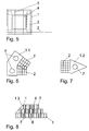
- FIG. 3 shows a further embodiment;
- the finished part 1 is formed trough-shaped.
- the bottom cylindrical recesses 7 are arranged for fasteners 8.
- a cuboid body made of lightweight material 4, namely polystyrene or equivalent, arranged.
- a reinforcement 3 is also arranged, which serves to avoid cracking in the concrete.
- the geogrid 2 is also arranged in the lower region of the finished part 1.
- the surface structure of the finished parts is arbitrarily adjustable, such as fracture gray or as a board formwork structure. Alternatively or additionally, the attachment of a Natural stone veneering possible.
- the invention is preferably used to construct non-or teilbeauxbarer and Steep and / or high retaining walls or noise barriers made of individual elements.
- Figure 4 shows a supporting wall, which was erected with finished parts 1 according to the invention, in a sectional view.
- the finished parts 1 are stacked side by side and one above the other, the lower row of finished parts 1 being placed on a cleanliness layer 5. All finished parts 1 with air-side contact have a back anchorage.
- the finished parts 1 of the upper three rows have a geogrid 2, the length of these geogrids 2 being different in different heights as a result of a static design.
- Three of the prefabricated parts 1 shown have a relatively short geogrid 2 on their rear side; These geogrids 2 are each connected to a further geogrid 2.1, which causes a back anchoring in an earth body 6.
- the geogrids 2 of the finished parts 1, which are connected to a further geogrid 2.1, are formed with a unit length.
- the finished parts 1 can be arranged vertically and / or horizontally, for example, unfurled or be provided with mortared joints 9.
- steel rods are mortared as connecting elements 8, respectively, so that their ends are in two different finished parts 1.
- connecting elements 8 are in two different finished parts 1.
- they connect two or three finished parts 1 with each other shear-resistant.
- the entire support wall becomes rigid.
- FIG. 5 shows a further embodiment of a finished part 1 according to the invention; the core of this finished part 1 is made of a lightweight material 4, which serves to reduce the weight.
- the formed of lightweight material 4 core this finished part 1 is completely covered by a reinforced with a reinforcement 3 concrete wall.
- the recesses 7 penetrate all areas vertically.
- FIG. 6 shows the plan view of a first special part 1.1.
- this first special section 1.1 is a trimmed from two blocks basic body, which is used for the production of angled in the floor plan support walls.
- a geogrid 2 is arranged in each case.
- the special part 1.1 has compatible recesses 7 to the control elements. As a result, it can be connected to other special parts 1.1 or control elements shear resistant.
- such first special parts 1.1 a prismatic basic shape with have a polygonal floor plan.
- Figure 7 shows a second special part 1.2, which is also suitable for the formation of angled in plan view of the support walls, said second special part 1.2 has a prismatic shape, wherein the floor plan of this prismatic body forms a triangle, which is for example isosceles. Also this special part 1.2 has a recess 7 for introduction and attachment of a connecting element 8.
- FIG. 8 shows the view of a supporting wall formed from a large number of prefabricated parts 1, wherein third special parts 1.3 are arranged on the lateral boundary of the supporting wall shown on the left, which likewise have a prismatic shape.
- the prisms shown here have a triangular view.
- the finished parts 1 are each connected in pairs by mortared steel rods as connecting elements 8 with respect to their vertical arrangement layers.
- the finished parts 1 can, with or without offset, namely perpendicular or inclined, to a Slope front to be stacked.
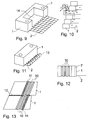
- Figure 9 shows a finished part 1 with two cylindrical, vertically arranged recesses 7 and a rectangular recess 14.
- the recess 14 extends over the upper and the rear surface of the finished part 1.
- the depth of the finished part is about twice as large as the depth of the other Prefabricated parts, so that this finished part in the installed state on the air side over the finished parts of lesser depth.
- the recess 14 serves to receive soil for planting a retaining wall.
- Such a planted support wall is shown in Figure 10 in section.
- the greenable finished part has a depth which is about twice as large as the depth of the other recessless finished parts of the retaining wall.
- the cuboid recess is filled with earth; this earth is directly connected to the back earth body, so that the plantings are supplied with water.
- FIG. 11 shows a prefabricated part 1 according to the invention prior to its use, ie in the transport state.
- a geotextile 2 is embedded in concrete, which is rolled up and fixed by means of a removable cover 13.
- the finished part 1 is easier to handle in the transport state;
- the geogrid 2 is protected against mechanical damage.
- a shell 13 is a glued or welded plastic film.
- FIG. 12 shows a prefabricated part 1 according to the invention with three encircling triangular grooves 10 and the cylindrical recesses 7 described above.
- the three grooves 10 run parallel and equally spaced over the upper, the lower and the side surfaces of the finished part 1 Grooves 10 vertical with respect to the basic shape of the finished part 1. It is also possible to produce this embodiment of the finished part 1 without recesses 7.
- FIG. 13 shows a modification of the finished part 1 shown in FIG. 12.
- three parallel, equally spaced triangular grooves 10 are arranged circumferentially.
- the air side of the finished part is formed inclined according to the intended support wall inclination.
- the recesses 7 are not shown here.
- the grooves are parallel with respect to the air-side surface of the support wall.
- the prefabricated parts 1 shown are suitable for use for a retaining wall, in which a plurality of identical finished parts, each with corresponding grooves is used.
- a groove 10 of each finished part 1 a circumferential, longitudinally stretched sealing element 11 is inserted such that at each intersection of the bearing joint and butt joint of the support wall sealing elements each adjacent finished parts offset from each other and do not overlap.
- sealing element 11 a bentonite round cord is used here.
- sealing members 11 made of rubber or injection hoses may be used.
- the sealing element 11 is inserted into the first groove 10 viewed from the air side; in the lower finished part 1, the sealing element 11 is inserted into the third groove 10 viewed from the air side;
- the sealing elements 11 of adjacent finished parts 1 do not touch.
- the thickness of the sealing elements 11 is selected and the modulus of elasticity of the sealing elements 11 is selected so that it fills two corresponding grooves 10 of two finished parts 1, wherein a defined gap between the finished parts 1 remains. The front portion of this gap, so the bearing joint is filled with mortar 12. It is also possible to produce this embodiment of the finished part 1 without recesses 7.
- FIG. 14 shows a further modification of the finished part 1 shown in FIG. 12.
- four parallel, equally spaced triangular grooves 10 are arranged circumferentially.
- the air side of the finished parts 1 is formed vertically.
- a reinforcing rod is shown here, which is concreted in as a connecting element 8.
- the grooves run parallel with respect to the air-side surface of the finished parts 1.
- the scheduled offset one above the other to be arranged precast parts 1 is denoted by v. It is important that the spacing of the grooves 10 is also v.
- the prefabricated parts 1 shown are suitable for use for a supporting wall, in which a multiplicity of identical prefabricated parts, each having corresponding grooves 10, are used.
- sealing element 11 inserted such that offset at each intersection of the bearing joint and butt joint of the support wall sealing elements each adjacent finished parts against each other and do not overlap.
- sealing member 11 rubber is used here.
- sealing elements 11 made of bentonite round cord or injection hoses can be used.
- the sealing element 11 is inserted into the third groove 10 viewed from the air side; in the lower finished part 1, the sealing element 11 is inserted into the second groove 10 viewed from the air side; As a result, the sealing elements 11 of the finished parts do not touch each other:
- the two adjacent and not shown prefabricated parts 1 of the prefabricated part 1 shown above carry their sealing element in the second and in the fourth joint.
- the thickness of the sealing elements 11 is also selected and the modulus of elasticity of the sealing elements 11 is selected so that it fills two corresponding grooves 10 of two finished parts 1, with a defined gap between the finished parts 1 remains. It is also possible to produce this embodiment of the finished part 1 without recesses 7
- Figure 15 shows a laying plan for finished parts 1 with grooves 10 for a supporting wall in association with continuous bearing joints, with a maximum of three finished parts 1 abut each other.
- the laying plan shows prefabricated parts to be laid, in which the numbers of the respective grooves 10 are entered, in which the respective sealing element 11 is to be inserted.
- inclined supporting walls are erected without offsets using the finished parts 1 shown in FIG. 13 or vertical supporting walls using the finished parts 1 shown in FIG. 12 or inclined supporting walls with offsets using the finished parts 1 shown in FIG.
- When erecting according to the installation plan shown ensures that at each intersection of the bearing joint and butt joint of the support wall sealing elements 11 each adjacent finished parts offset from each other and do not overlap or touch.
- FIG. 16 shows a laying plan for finished parts 1 with grooves 10 for a retaining wall in association with continuous bearing joints and with continuous butt joints, that is to say that in each case four finished parts 1 abut one another.
- the laying plan shows prefabricated parts to be laid, in which the numbers of the respective grooves 10 are entered, in which the respective sealing element 11 is to be inserted.
- this laying plan inclined support walls without offsets using the finished parts 1 shown in Figure 13 - but with four parallel grooves 10 - or vertical support walls using the finished parts 1 shown in Figure 14 - but without offset - built.
- When erecting according to the installation plan shown ensures that at each intersection of the bearing joint and butt joint of the support wall sealing elements 11 each adjacent finished parts offset from each other and do not overlap or touch.
- At least one of the finished parts 1 with an air side Covering or an optically visible profiling provided.
- all Prefabricated parts 1 of a retaining wall visually uniform.
Abstract
Description
Die Erfindung betrifft ein stapelbares Fertigteil aus Beton, das mit einem Geogitter verbindbar ist, insbesondere zur Herstellung von Stützwänden aus einzelnen Elementen.The invention relates to a stackable precast concrete, which can be connected to a geogrid is, in particular for the production of retaining walls of individual elements.
Im Stand der Technik sind neben diversen Böschungssicherungssystemen und Stützwandsystemen verschiedene stapelbare Fertigteile aus Beton zur Herstellung von Stützwänden aus einzelnen Elementen bekannt.In the prior art are in addition to various slope protection systems and Retaining wall systems various stackable precast concrete elements for the production of Support walls known from individual elements.
Nach DE 81 19 371 U1, DE 88 11 825 U1, DE 38 37 243 A1 und AT 004 473 U1 sind stapelbare Elemente für Stützwandsysteme bekannt, bei denen jeweils übereinander angeordnete Elemente miteinander verbunden werden, um die Standsicherheit dieser Stützwände zu erhöhen.According to DE 81 19 371 U1, DE 88 11 825 U1, DE 38 37 243 A1 and AT 004 473 U1 are Stackable elements known for retaining wall systems, where each one above the other arranged elements are interconnected to the stability of this To increase retaining walls.
Nach AT 004 473 U 1 ist ein Bauteil zur Errichtung von Stützwandelementen bekannt, bei dem an einem quaderförmigen Grundelement zumindest an einem Teil seiner Begrenzungsflächen eine oder mehr als eine Nut angeordnet ist, wobei diese Nut(en) zur formschlüssigen Verbindung aneinander anschließender Grundelemente eine leistenförmige Feder als Verbindungselement einsetzbar ist.According to AT 004 473 U 1, a component for the construction of supporting wall elements is known, in the at a cuboidal base element at least on a part of his Bounding surfaces is arranged one or more than one groove, said groove (s) for positive connection of adjoining basic elements a strip-shaped Spring can be used as a connecting element.
Nach DE 38 372 43 A 1 ist ein Formstein mit einer endlos ausgebildeten Seitenwand und einer oberen und unteren Öffnung zur Aufnahme von Erdreich oder dergleichen für die Herstellung einer aus neben- und übereinander angeordneten Formsteinen gebildeten Mauer bekannt, wobei die Seitenwand einen maueraußen- und -innenseitigen Bereich sowie zwei diese miteinander verbindende Querwände aufweist, bei der im oberen Stirnendbereich jeder Querwand eine von der Ebene der Stirnfläche abstehende Fixiernase und an der Innenseite jeder Querwand eine von dieser nach innen abstehende und mit der Unterkante der Querwand bündig abschließende Halteleiste vorgesehen ist.According to DE 38 372 43 A1 is a molded block with an endlessly formed side wall and an upper and lower opening for receiving soil or the like for the Production of a wall formed from juxtaposed and stacked form stones known, wherein the side wall has a wall outside and inside area and two has these interconnecting transverse walls, in the upper Stirnendbereich everyone Transverse wall a projecting from the plane of the end face fixing lug and on the inside each transverse wall one from this inwardly projecting and with the lower edge of the transverse wall flush final retaining strip is provided.
Nach DE 88 11 825 U 1 ist eine Stützwand bekannt, die ein im wesentlichen plattenförmiges
Basiselement, welches eine parallel zu einer Seitenkante verlaufende Rippe aufweist, enthält,
wobei ein im wesentlichen quaderförmiges Anschlusselement, welches mit einer zu einer
Rippe passenden Linksnut versehen ist, angeordnet ist.According to DE 88 11 825
Nachteilig ist bei den vorgenannten Anordnungen, dass diese bekannten Systeme nicht zur Herstellung relativ hoher oder steiler Stützwände geeignet sind, da diese Systeme nach dem Prinzip einer nicht rückverankerten und unbewehrten Schwergewichtswand wirken.A disadvantage of the aforementioned arrangements that these known systems not for Production of relatively high or steep support walls are suitable because these systems after the Principle of a non-anchored and unreinforced heavyweight wall effect.
Nach DE 200 11 791.2 U 1 ist eine Anordnung zur Errichtung von Stützbauwerken und
Steilböschungen mit kunststoffbewehrter Erde und dauerhafter Begrünung bekannt, bei der
der erdseitige Bereich der Böschung aus horizontalen Schichten aufgebaut ist, zwischen
denen Geokunststoffbewehrungen angeordnet sind, bei denen als verlorene Schalung
dienende abgewinkelte Bewehrungsmatten angeordnet sind und bei denen zur Fixierung der
verlorenen Schalung zwischen Schenkelflächen der abgewinkelten Bewehrungsmatten
Abstandhalter angeordnet sind. Durch die Anordnung von rückverankerten Geotextilien ergibt
sich für diese Böschungen eine gute Standsicherheit und eine sehr gute Begrünbarkeit.According to DE 200 11 791.2
Nachteilig ist dabei, dass zur Vermeidung von Beeinträchtigungen der Tragfähigkeit durch Erosion eine Begrünung unentbehrlich ist.The disadvantage here is that in order to avoid adverse effects on the load capacity Erosion a greening is indispensable.
Darüber hinaus ist es bekannt, Stützwände aus stapelbaren Fertigteilen zu errichten und in den Lagerfugen jeweils übereinander angeordneter Formsteine Geotextilien lose zu verlegen und erdseitig zu verankern.In addition, it is known to build supporting walls of stackable precast and in the Laying joints in each case arranged on one another arranged stones geotextiles loosely and anchor on the earth side.
Nachteilig ist dabei, dass eine Zugkrafteinleitung aus den Geotextilien in die stapelbaren Formsteine nur durch Reibung nur möglich ist, wenn die aus den stapelbaren Fertigteilen gebildete Stützwand einer ausreichend hohen Vertikalkraft ausgesetzt ist. Dies ist jedoch regelmäßig nicht der Fall.The disadvantage here is that a tensile force from the geotextiles in the stackable Forming stones only by friction is only possible if those from the stackable precast formed support wall is exposed to a sufficiently high vertical force. This is however regularly not the case.
Der Erfindung liegt die Aufgabe zugrunde, ein verbessertes Fertigteil aus Beton anzugeben, mit dem auf einfache Weise standsichere Stützwände errichtet werden können.The invention has for its object to provide an improved precast concrete, can be built with the easily stable stable retaining walls.
Erfindungsgemäß wird die Aufgabe mit einem stapelbaren Fertigteil, welches die in Anspruch
1 angegebenen Merkmale aufweist, gelöst. According to the invention, the object with a stackable finished part, which the
Vorteilhafte Ausgestaltungen sind Gegenstand der abhängigen Ansprüche.Advantageous embodiments are the subject of the dependent claims.
Die Erfindung sieht ein stapelbares Fertigteil aus Beton vor, das mit einem Geogitter verbunden ist, insbesondere zur Herstellung von Stützwänden aus einzelnen Elementen, wobei das Fertigteil mindestens eine vertikal durchgängige Ausnehmung aufweist, in die mindestens ein Verbindungselement einbringbar ist.The invention provides a stackable precast concrete, with a geogrid is connected, in particular for the production of supporting walls from individual elements, wherein the finished part has at least one vertically continuous recess in the at least one connecting element can be introduced.
Durch derartige Fertigteile mit einem Geogitter und einer oder mehreren vertikal durchgängigen Ausnehmungen, in die jeweils mindestens ein Verbindungselement einbringbar ist, gelingt es, eine Stützwand mit einfach herstellbarer Rückverankerung zu errichten, bei der alle einzelnen Fertigteile direkt oder indirekt schubsteif miteinander verbunden werden können, wodurch die gesamte Stützwand schubsteif ausgebildet wird. Lokale Belastungen werden so auf alle Teile der Stützwand verteilt. Die Fertigteile sind dabei einfach herstellbar.By such finished parts with a geogrid and one or more vertically continuous recesses, in each case at least one connecting element can be introduced, it succeeds to a supporting wall with easy to produce back anchoring in which all individual finished parts are directly or indirectly shear-resistant with each other can be connected, whereby the entire support wall is formed shear stiff. Local loads are thus distributed to all parts of the supporting wall. The finished parts are included easy to produce.
Eine vorteilhafte Ausgestaltung sieht dabei vor, dass das Geogitter mit einem weiteren Geogitter verbindbar ist. Dieses weitere Geogitter kann großflächig ausgebildet sein und tief im Erdkörper verankert werden. Vorteilhaft ist dabei, dass im Transportzustand das Fertigteil lediglich ein kleinflächiges und damit einfacher vor mechanischer Beschädigung zu schützendes Geogitter aufweisen muss. Alternativ ist es möglich, das Geogitter im Transportzustand des Fertigteils aufgerollt mittels einer entfernbaren Hülle zu fixieren, um den vorgenannten Vorteil zu erzielen. Als Hülle eignet sich eine geklebte oder geschweißte Kuststofffolie.An advantageous embodiment provides that the geogrid with another Geogrid is connectable. This additional geogrid can be designed over a large area and deep anchored in the earth. It is advantageous that in the transport state, the finished part only a small area and thus easier against mechanical damage too must have protective geogrid. Alternatively, it is possible to use the geogrid in the Transport state of the finished part rolled up by means of a removable cover to fix to achieve the aforementioned advantage. As a shell is a glued or welded Kuststofffolie.
Eine hohe Stabilität des Fertigteiles ist in einer besonderen Ausführungsform durch eine Bewehrung, vorzugsweise aus Baustahl, in dem Fertigteil möglich.A high stability of the finished part is in a particular embodiment by a Reinforcement, preferably made of structural steel, possible in the finished part.
Gemäß einer weiteren Ausgestaltung ist zur Gewichtsreduzierung in dem Fertigteil ein Körper aus Leichtstoff oder im Kern des Fertigteiles ein Hohlraum angeordnet. Dies erleichtert den Transport und die Verwendung des Fertigteils. According to a further embodiment, a body is for weight reduction in the finished part made of lightweight or arranged in the core of the finished part a cavity. This facilitates the Transport and use of the finished part.
Vorzugsweise reicht dabei der Körper aus Leichtstoff in dem Fertigteil bis zu mindestens einer Seite des Fertigteiles und ist entfernbar. Damit kann in einfacher Weise eine Aussparung im Fertigteil ohne schalungstechnischen Aufwand, nämlich nachträglich geschaffen werden.Preferably, the body of lightweight material in the finished part extends to at least one side of the finished part and is removable. This can easily a recess in the finished part without formwork expense, namely to be created later.
Gemäß einer weiteren Ausgestaltung wird die vorgenannte Aussparung im Wesentlichen quaderförmig ausgebildet und bildet eine Ausnehmung an der Oberseite und an der Rückseite des Fertigteiles. Damit wird ein begrünbares Fertigteil geschaffen, das zur Verwendung in erfindungsgemäßen Stützwänden geeignet ist. Dieses begrünbare Fertigteil weist eine Tiefe auf, die etwa doppelt so groß ist wie die Tiefe der sonstigen Fertigteile der Stützwand. Vorteilhaft ist insbesondere, die quaderförmige Aussparung mit Erde zu befüllen, da diese Erde unmittelbar mit dem rückseitigen Erdkörper in Verbindung steht, so dass Anpflanzungen gut mit Wasser versorgt sind.According to a further embodiment, the aforementioned recess is substantially formed cuboid and forms a recess at the top and at the back of the finished part. Thus, a greenable finished part is created, which is suitable for use in Support walls according to the invention is suitable. This green finished part has a depth which is about twice as large as the depth of the other finished parts of the retaining wall. It is particularly advantageous to fill the cuboid recess with earth, as these Earth is directly related to the back earth body, so that plantings are well supplied with water.
In einer weiteren bevorzugten Ausgestaltung ist das Geogitter in das Fertigteil einbetoniert. Dadurch sind große Zugkräfte von dem Fertigteil in das Geogitter einleitbar.In a further preferred embodiment, the geogrid is cast in the prefabricated part. As a result, large tensile forces from the finished part in the geogrid can be introduced.
In einer weiteren Ausgestaltung sind an dem Fertigteil Montageösen angeordnet. Diese ermöglichen einen einfachen und sicheren Transport und eine einfache Verarbeitung des Fertigteils beim Errichten einer Stützwand.In a further embodiment, assembly loops are arranged on the finished part. These enable easy and safe transport and easy processing of the Prefabricated when building a retaining wall.
In einer weiteren Ausgestaltung ist an dem Fertigteil (1) wenigstens eine durchgehende Nut angeordnet ist, wobei die wenigstens eine Nut über die obere, die untere sowie über die Seitenflächen verlaufen, wobei längs gestreckte Dichtungselemente in die Nuten einlegbar sind. Damit können Fertigteile in einer Stützwand gegenseitig abgedichtet werden, so dass Ausspülungen des Erdkörpers durch Fugen zwischen verbauten Fertigteilen reduziert oder vermieden werden.In a further embodiment, at least one continuous groove on the finished part (1) is arranged, wherein the at least one groove on the upper, the lower and on the Side surfaces extend, with longitudinally stretched sealing elements inserted into the grooves are. This allows finished parts to be mutually sealed in a retaining wall, so that Rinses of the earth body reduced by joints between installed prefabricated parts or be avoided.
Vorzugsweise sind dabei wenigstens drei Nuten angeordnet, die in der Regel parallel verlaufen. Derartige Fertigteile eignen sich zur Verwendung für eine Stützwand, bei der eine Vielzahl identischer Fertigteile mit jeweils korrespondierenden Nuten verwendet wird. Dabei wird in jeweils eine Nut jedes Fertigteiles (1) ein umlaufendes, längs gestrecktes Dichtungselement derart eingelegt, dass an jedem Kreuzungspunkt von Lagerfuge und Stoßfuge der Stützwand Dichtungselemente jeweils benachbarter Fertigteile versetzt gegeneinander verlaufen und sich nicht überschneiden. Auf einfache Weise können bei Einhaltung einfacher Verlegepläne dichte Stützwände errichtet werden.Preferably, at least three grooves are arranged, which are usually parallel run. Such prefabricated parts are suitable for use for a retaining wall, in which a Variety of identical finished parts, each with corresponding grooves is used. there is in each case a groove of each finished part (1) a circumferential, longitudinally stretched Inserted sealing element such that at each intersection of the bearing joint and Butt joint of the support wall offset sealing elements of adjacent finished parts run against each other and do not overlap. In a simple way can at Compliance with simple installation plans dense retaining walls are built.
Gemäß einer bevorzugten Verwendung der Fertigteile für eine Stützwand wird mindestens eines der Fertigteile mit einem oder mehreren anderen Fertigteilen durch mit Verbindungselementen gekoppelt. Dabei werden Verbindungselemente in korrespondierende Ausnehmungen benachbart beziehungsweise übereinander verlegter Fertigteile jeweils teilweise eingebracht und in den Ausnehmungen befestigt. Dadurch werden Stützwände errichtet, die neben einer hohen Standsicherheit auch eine hohe Schubsteifigkeit aufweisen und damit weniger zu Verformungen neigen.According to a preferred use of the finished parts for a retaining wall is at least one of the finished parts with one or more other finished parts by with Coupled connection elements. In this connection elements are in corresponding Recesses adjacent or superimposed finished parts respectively partially inserted and secured in the recesses. This will be retaining walls built, which in addition to a high stability and also have a high shear stiffness and thus less prone to deformation.
In einer bevorzugten Ausgestaltung sind dabei Geogitter verschiedener Fertigteile mit einander gekoppelt. Dadurch wird eine gleichmäßige Lasteileitung in den Erdkörper ermöglicht und lokale Schwachstellen im Verbund zwischen Geotextilien und Erdreich werden überbrückt.In a preferred embodiment, geogrids of various finished parts are included coupled together. This results in a uniform Lasesteitung in the earth body allows and local vulnerabilities in the bond between geotextiles and soil be bridged.
Zweckmäßigerweise ist unterhalb einer ersten Lage von Fertigteilen ein Bodenaustausch oder eine Sauberkeitsschicht angeordnet. Dies erhöht die zu erwartende Lebensdauer der Stützwand.Appropriately, below a first layer of finished parts, a soil replacement or arranged a cleanliness layer. This increases the expected life of the Retaining wall.
Die Erfindung wird im Folgenden anhand von Ausführungsbeispielen näher erläutert.The invention will be explained in more detail below with reference to exemplary embodiments.
Dazu zeigen:
Figur 1- eine isometrische Darstellung eines einzelnen erfindungsgemäßen Fertigteils,
Figur 2- eine zugehörige Seitenansicht,
Figur 3- eine Seitenansicht eines einzelnen erfindungsgemäßen Fertigteils in einer weiteren Ausführungsform,
Figur 4- einen Schnitt durch eine aus erfindungsgemäßen Fertigteilen hergestellte Stützwand,
Figur 5- einen Schnitt durch eine weitere Ausführungsform eines erfindungsgemäßen Fertigteils,
Figur 6- eine Draufsicht eines ersten Sonderelementes,
Figur 7- eine Draufsicht eines zweiten Sonderelementes,
Figur 8- einen Ausschnitt einer Ansicht einer aus erfindungsgemäßen Fertigteilen errichteten Stützwand,
Figur 9- eine perspektivische Ansicht eines einzelnen erfindungsgemäßen Fertigteils in einer Ausführungsform mit Aussparung,
Figur 10- eine zugehörige Schnittdarstellung dieses Fertigteils mit anderen Fertigteilen,
Figur 11- eine perspektivische Ansicht einer weiteren Ausführungsform des erfindungsgemäßen Fertigteils mit aufgerolltem Geotextil,
Figur 12- eine Seitenansicht einer weiteren Ausführungsform des erfindungsgemäßen Fertigteils mit Nuten,
Figur 13- eine Seitenansicht einer weiteren Ausführungsform des erfindungsgemäßen Fertigteils mit Nuten im Verbund,
Figur 14- eine Seitenansicht einer weiteren Ausführungsform des erfindungsgemäßen Fertigteils mit Nuten im Verbund,
- Figur 15
- einen ersten Verlegeplan für Fertigteile mit Nuten und
- Figur 16
- einen zweiten Verlegeplan für Fertigteile mit Nuten.
- FIG. 1
- an isometric view of a single finished part according to the invention,
- FIG. 2
- an associated side view,
- FIG. 3
- a side view of a single finished part according to the invention in a further embodiment,
- FIG. 4
- a section through a retaining wall made of finished parts according to the invention,
- FIG. 5
- a section through a further embodiment of a precast element according to the invention,
- FIG. 6
- a top view of a first special element,
- FIG. 7
- a top view of a second special element,
- FIG. 8
- a detail of a view of a built-up from precast elements of the invention supporting wall,
- FIG. 9
- 3 is a perspective view of a single prefabricated part according to the invention in an embodiment with recess,
- FIG. 10
- an associated sectional view of this finished part with other finished parts,
- FIG. 11
- a perspective view of another embodiment of the finished product according to the invention with rolled geotextile,
- FIG. 12
- a side view of another embodiment of the finished part according to the invention with grooves,
- FIG. 13
- a side view of another embodiment of the finished part according to the invention with grooves in the composite,
- FIG. 14
- a side view of another embodiment of the finished part according to the invention with grooves in the composite,
- FIG. 15
- a first installation plan for precast parts with grooves and
- FIG. 16
- a second installation plan for precast elements with grooves.
Figur 1 zeigt ein als Regelelement einsetzbares quaderförmiges Fertigteil 1 mit einer
Elementbreite von etwa 1,0 m und einer Elementhöhe und einer Elementtiefe von etwa 50 cm,
das aus Beton gefertigt ist. In das Fertigteil 1 ist ein Geogitter 2, das aus Kunststoff besteht
und eine Zugfestigkeit nach statischem Erfordernis aufweist, einbetoniert. Das Geogitter 2
ist in einem Erdkörper verankerbar. Das Fertigteil weist zwei zylinderförmige, vertikale
Ausnehmungen 7 mit einem identischen Durchmesser von etwa 5 cm auf, die in radialer
Richtung vollständig von Beton umschlossen sind. In diese Ausnehmungen 7 können im
Zuge der Montage längliche Verbindungselemente 8, beispielsweise Stahlstäbe mit einem
Durchmesser von 20 mm, eingebracht und darin befestigt werden, beispielsweise durch
Einmörteln oder Betonieren. In diesem Fall sind die Abstände des Geogitters 2 größer als
die Durchmesser der Ausnehmungen 7, sodass diese relativ zum Geogitter 2 in dessen Lücken
angeordnet sind. Ansonsten oder alternativ dazu kann das Geogitter 2 in den Bereichen der
Ausnehmungen 7 unterbrochen sein. Figure 1 shows a usable as a control element cuboid finished
Grundsätzlich kann ein Fertigteil 1 eine einzige oder mehrere Ausnehmungen 7 aufweisen. Im
Falle mehrerer Ausnehmungen 7 weisen diese vorzugsweise identische Maße auf. Die
einzelnen oder mehreren Ausnehmungen 7 können beliebige Querschnitte aufweisen,
beispielsweise quadratisch, kreisförmig, vieleckig oder elliptisch. Der Querschnitt einer
Ausnehmungen 7 kann entlang ihrer Längsrichtung variieren. Dabei sind die Maße der
Ausnehmungen 7 vorzugsweise so groß, dass diese bei einem anzunehmenden maximalen
Versatz übereinander angeordneter Fertigteile 1 noch mit Ausnehmungen angrenzender
Fertigteile 1 um mindestens die Dicke zugehöriger Verbindungselemente 8 überlappen.
Dann kann jeweils ein Verbindungselement 8 in den Ausnehmungen 7 mehrerer über
einander liegender Fertigteile 1 angeordnet und befestigt werden, sodass es mindestens zwei
Fertigteile 1 schubsteif verbindet. Vorzugsweise sind im Falle mehrerer Ausnehmungen 7
diese parallel zueinander angeordnet.In principle, a
Alternativ gelingt die verbindende Anordnung der Verbindungselemente 8 mittels einer
größeren Anzahl kleinerer Ausnehmungen 7, die in Versatzrichtung in Linien
hintereinander angeordnet sind, sodass die Abstände der Ausnehmungen 7 in dieser Richtung
die möglichen Versatzalternativen vorgeben.Alternatively, the connecting arrangement of the connecting
Figur 2 zeigt eine Seitenansicht des in Figur 1 dargestellten, als Regelelement einsetzbaren
Fertigteils 1, das aus Beton gefertigt ist; in dem quaderförmigen Fertigteil 1 ist eine
Bewehrung 3, die aus Baustahl besteht, angeordnet; das Geogitter 2 ist in das Fertigteil 1
einbetoniert und tritt rechtwinklig aus einer Rückseite des Fertigteiles 1 in dessen unterem
Bereich aus. Die Länge des außerhalb des Fertigteiles 1 angeordneten Geogitters 2 ist durch
die statische Bemessung bestimmt. Die Bewehrung 3 ist so angeordnet, dass die
Ausnehmungen 7 dazwischen liegen. Alternativ kann die Bewehrung 3 an diesen Stellen
unterbrochen sein. Figure 2 shows a side view of the illustrated in Figure 1, usable as a control element precast 1, which is made of concrete; in the cuboid
Figur 3 zeigt eine weitere Ausführungsform; dabei ist das Fertigteil 1 trogförmig ausgebildet.
Im Boden sind zylinderförmige Ausnehmungen 7 für Verbindungselemente 8 angeordnet. In
dem inneren Bereich des Fertigteiles 1 ist ein ebenfalls quaderförmiger Körper aus Leichtstoff
4, nämlich aus Styropor oder gleichwertigem, angeordnet. In den Wandungen und in dem
Bodenbereich des Fertigteiles 1 ist ebenfalls eine Bewehrung 3 angeordnet, die der
Vermeidung von Rissbildungen im Beton dient. Das Geogitter 2 ist ebenfalls im unteren
Bereich des Fertigteiles 1 angeordnet. FIG. 3 shows a further embodiment; In this case, the
Die Oberflächenstruktur der Fertigteile ist beliebig einstellbar, beispielsweise bruchrau oder als Brettverschalungsstruktur. Alternativ oder zusätzlich ist die Befestigung einer Natursteinverblendung möglich.The surface structure of the finished parts is arbitrarily adjustable, such as fracture gray or as a board formwork structure. Alternatively or additionally, the attachment of a Natural stone veneering possible.
Die Erfindung wird vorzugsweise verwendet zur Errichtung nicht- oder teilbegrünbarer und steiler und/oder hoher Stützwände oder Lärmschutzwände aus einzelnen Elementen.The invention is preferably used to construct non-or teilbegrünbarer and Steep and / or high retaining walls or noise barriers made of individual elements.
Figur 4 zeigt eine Stützwand, die mit erfindungsgemäßen Fertigteilen 1 errichtet wurde, in
Schnittdarstellung. Die Fertigteile 1 sind nebeneinander und übereinander gestapelt, wobei die
untere Reihe von Fertigteilen 1 auf einer Sauberkeitsschicht 5 aufgestellt wurde. Alle
Fertigteile 1 mit luftseitigem Kontakt weisen eine Rückverankerung auf. Die Fertigteile 1 der
oberen drei Reihen weisen ein Geogitter 2 auf, wobei die Länge dieser Geogitter 2 in
unterschiedlichen Höhen als Ergebnis einer statischen Bemessung unterschiedlich ist. Drei der
dargestellten Fertigteile 1 weisen an ihrer Rückseite ein relativ kurzes Geogitter 2 auf; diese
Geogitter 2 sind jeweils mit einem weiteren Geogitter 2.1 verbunden, welches eine
Rückverankerung in einen Erdkörper 6 bewirkt. Die Geogitter 2 der Fertigteile 1, die mit
einem weiteren Geogitter 2.1 verbunden sind, sind mit einer Einheitslänge ausgebildet. Die
Fertigteile 1 können vertikal und/oder horizontal beispielsweise unverfugt angeordnet oder
mit vermörtelten Fugen 9 versehen sein. In die Ausnehmungen 7 der Fertigteile 1 sind
Stahlstäbe als Verbindungselemente 8 jeweils eingemörtelt, sodass ihre Enden in zwei
verschiedenen Fertigteilen 1 liegen. Dadurch verbinden sie zwei oder drei Fertigteile 1
untereinander schubsteif. Durch die Fortsetzung der paarweisen oder mehrfachen Verbindung
wird die gesamte Stützwand schubsteif. Figure 4 shows a supporting wall, which was erected with
Figur 5 zeigt eine weitere Ausführungsform eines erfindungsgemäßes Fertigteiles 1; der
Kern dieses Fertigteiles 1 ist aus einem Leichtstoff 4 gefertigt, der zur Reduzierung des
Gewichtes dient. Der aus Leichtstoff 4 gebildete Kern dieses Fertigteiles 1 ist von einer mit
einer Bewehrung 3 bewehrten Betonwand vollflächig umhüllt. Die Ausnehmungen 7
durchdringen alle Bereiche vertikal. FIG. 5 shows a further embodiment of a
Figur 6 zeigt die Draufsicht eines ersten Sonderteiles 1.1. Bei diesem ersten Sonderteil 1.1
handelt es sich um ein aus zwei Quadern verschnittenen Grundkörper, der zur Herstellung von
im Grundriss abgewinkelten Stützwänden dient. An der Rückseite eines jeden Teilquaders,
der dieses erste Sonderteil 1.1 bildet, ist jeweils ein Geogitter 2 angeordnet. Das Sonderteil
1.1 weist zu den Regelelementen kompatible Ausnehmungen 7 auf. Dadurch kann es mit
anderen Sonderteilen 1.1 oder Regelelementen schubsteif verbunden werden. FIG. 6 shows the plan view of a first special part 1.1. In this first special section 1.1 is a trimmed from two blocks basic body, which is used for the production of angled in the floor plan support walls. At the back of each partial cuboid, which forms this first special part 1.1, a
Im allgemeinen Fall können derartige erste Sonderteile 1.1 eine prismatische Grundform mit einem vieleckigen Grundriss aufweisen.In the general case, such first special parts 1.1 a prismatic basic shape with have a polygonal floor plan.
Figur 7 zeigt ein zweites Sonderteil 1.2, welches ebenfalls zur Ausbildung von im Grundriss
abgewinkelten Stützwänden geeignet ist, wobei dieses zweite Sonderteil 1.2 eine prismatische
Form aufweist, wobei der Grundriss dieses prismatischen Körpers ein Dreieck bildet, das
beispielhaft gleichschenklig ist. Auch dieses Sonderteil 1.2 weist eine Ausnehmung 7 zur
Einbringung und Befestigung eines Verbindungselementes 8 auf. Figure 7 shows a second special part 1.2, which is also suitable for the formation of angled in plan view of the support walls, said second special part 1.2 has a prismatic shape, wherein the floor plan of this prismatic body forms a triangle, which is for example isosceles. Also this special part 1.2 has a
Figur 8 zeigt die Ansicht einer aus einer Vielzahl von Fertigteilen 1 gebildeten Stützwand,
wobei an der links dargestellten seitlichen Begrenzung der Stützwand dritte Sonderteile 1.3
angeordnet sind, die ebenfalls eine prismatische Form aufweisen. Die hier dargestellten
Prismen weisen eine dreieckige Ansicht auf. Die Fertigteile 1 sind bezüglich ihrer vertikalen
Anordnungsschichten jeweils paarweise durch eingemörtelte Stahlstäbe als
Verbindungselemente 8 verbunden. FIG. 8 shows the view of a supporting wall formed from a large number of
Die in den Figuren 6 bis 8 dargestellten Sonderelemente 1.1, 1.2, 1.3 sind mit beliebigen Winkeln herstellbar, so dass Stützwände mit beliebigem Verlauf im Grundriss sowie mit beliebigen Rand- und Kopfausbildungen herstellbar sind.The illustrated in Figures 6 to 8 special elements 1.1, 1.2, 1.3 are arbitrary Angle can be produced, so that retaining walls with any course in the plan as well as with can be produced arbitrary edge and head training.
Die Fertigteile 1 können mit oder ohne Versatz, und zwar lotrecht oder geneigt, an einer
Böschungsfront gestapelt werden.The
Figur 9 zeigt ein Fertigteil 1 mit zwei zylindrischen, vertikal angeordneten Ausnehmungen 7
und einer quaderförmigen Aussparung 14. Die Aussparung 14 erstreckt sich über die obere
und die hintere Fläche des Fertigteils 1. Die Tiefe des Fertigteiles ist etwa doppelt so groß wie
die Tiefe der sonstigen Fertigteile, so dass dieses Fertigteil im eingebauten Zustand luftseitig
gegenüber den Fertigteilen geringerer Tiefe übersteht. Die Aussparung 14 dient zur
Aufnahme von Erde zur Begrünung einer Stützwand. Figure 9 shows a
Eine derart begrünte Stützwand ist in Figur 10 im Schnitt dargestellt. Das begrünbare Fertigteil weist eine Tiefe auf, die etwa doppelt so groß ist wie die Tiefe der sonstigen aussparungslosen Fertigteile der Stützwand. Die quaderförmige Aussparung ist mit Erde befüllt; diese Erde steht unmittelbar mit dem rückseitigen Erdkörper in Verbindung, so dass die Anpflanzungen mit Wasser versorgt sind.Such a planted support wall is shown in Figure 10 in section. The greenable finished part has a depth which is about twice as large as the depth of the other recessless finished parts of the retaining wall. The cuboid recess is filled with earth; this earth is directly connected to the back earth body, so that the plantings are supplied with water.
Figur 11 zeigt ein erfindungsgemäßes Fertigteil 1 vor seiner Verwendung, also im
Transportzustand. In das Fertigteil 1 ist ein Geotextil 2 einbetoniert, welches aufgerollt und
mittels einer entfernbaren Hülle 13 fixiert ist. Dadurch ist im Transportzustand das Fertigteil 1
einfacher zu handhaben; dabei ist das Geogitter 2 vor mechanischer Beschädigung geschützt.
Als Hülle 13 eignet sich eine geklebte oder geschweißte Kuststofffolie. FIG. 11 shows a
Figur 12 zeigt ein erfindungsgemäßes Fertigteil 1 mit drei umlaufend angeordneten
dreikantförmigen Nuten 10 und den oben beschriebenen zylinderförmigen Ausnehmungen 7.
Die drei Nuten 10 verlaufen parallel und gleich beabstandet über die obere, die untere sowie
über die Seitenflächen des Fertigteils 1. An den Seitenflächen verlaufen die Nuten 10 vertikal
bezüglich der Grundform des Fertigteils 1. Es ist auch möglich, diese Ausführungsform des
Fertigteils 1 ohne Ausnehmungen 7 herzustellen. FIG. 12 shows a
Figur 13 zeigt eine Abwandlung des in Figur 12 gezeigten Fertigteils 1. Hier sind umlaufend
drei parallele, gleich beabstandete dreikantförmige Nuten 10 angeordnet. Die Luftseite des
Fertigteils ist entsprechend der vorgesehenen Stützwandneigung geneigt ausgebildet. Die
Ausnehmungen 7 sind hier nicht gezeigt. An den Seitenflächen verlaufen die Nuten parallel
bezüglich der luftseitigen Fläche der Stützwand. Die dargestellten Fertigteile 1 eignen sich zur
Verwendung für eine Stützwand, bei der eine Vielzahl identischer Fertigteile mit jeweils
korrespondierenden Nuten verwendet wird. Dazu wird in jeweils eine Nut 10 jedes
Fertigteiles 1 ein umlaufendes, längs gestrecktes Dichtungselement 11 derart eingelegt, dass
an jedem Kreuzungspunkt von Lagerfuge und Stoßfuge der Stützwand Dichtungselemente
jeweils benachbarter Fertigteile versetzt gegeneinander verlaufen und sich nicht
überschneiden. Als Dichtungselement 11 ist hier eine Bentonit-Rundschnur verwendet.
Alternativ können Dichtungselemente 11 aus Gummi oder Verpressschläuche verwendet
werden. Bei dem oberen Fertigteil 1 ist das Dichtungselement 11 in die von der Luftseite
betrachtet erste Nut 10 eingelegt; bei dem unteren Fertigteil 1 ist das Dichtungselement 11 in
die von der Luftseite betrachtet dritte Nut 10 eingelegt; dadurch berühren sich die
Dichtungselemente 11 benachbarter Fertigteile 1 nicht. Die Dicke der Dichtungselemente 11
ist so gewählt und der Elastizitätsmodul der Dichtungselemente 11 ist so gewählt, dass es
jeweils zwei korrespondierende Nuten 10 zweier Fertigteile 1 ausfüllt, wobei ein definierter
Spalt zwischen den Fertigteilen 1 verbleibt. Der vordere Bereich dieses Spaltes, also der
Lagerfuge, ist mit Mörtel 12 gefüllt. Es ist auch möglich, diese Ausführungsform des
Fertigteils 1 ohne Ausnehmungen 7 herzustellen. FIG. 13 shows a modification of the
Figur 14 zeigt eine weitere Abwandlung des in Figur 12 gezeigten Fertigteils 1. Hier sind
umlaufend vier parallele, gleich beabstandete dreikantförmige Nuten 10 angeordnet. Die
Luftseite der Fertigteile 1 ist vertikal ausgebildet. In den Ausnehmungen 7 ist hier ein
Bewehrungsstab gezeigt, der als Verbindungselement 8 einbetoniert ist. An den Seitenflächen
verlaufen die Nuten parallel bezüglich der luftseitigen Fläche der Fertigteile 1. Der
planmäßige Versatz übereinander anzuordnender Fertigteile 1 ist mit v bezeichnet. Es ist
wichtig, dass auch der Abstand der Nuten 10 jeweils v beträgt. Die dargestellten Fertigteile 1
eignen sich zur Verwendung für eine Stützwand, bei der eine Vielzahl identischer Fertigteile
mit jeweils korrespondierenden Nuten 10 verwendet wird. Auch hier wird in jeweils eine Nut
10 jedes Fertigteiles 1 ein umlaufendes, längs gestrecktes Dichtungselement 11 derart
eingelegt, dass an jedem Kreuzungspunkt von Lagerfuge und Stoßfuge der Stützwand
Dichtungselemente jeweils benachbarter Fertigteile versetzt gegeneinander verlaufen und sich
nicht überschneiden. Als Dichtungselement 11 ist hier Gummi verwendet. Alternativ können
Dichtungselemente 11 aus Bentonit-Rundschnur oder Verpressschläuche verwendet werden.
Bei dem oberen Fertigteil 1 ist das Dichtungselement 11 in die von der Luftseite betrachtet
dritte Nut 10 eingelegt; bei dem unteren Fertigteil 1 ist das Dichtungselement 11 in die von
der Luftseite betrachtet zweite Nut 10 eingelegt; dadurch berühren sich die
Dichtungselemente 11 der Fertigteile nicht: Die beiden jeweils benachbarten und hier nicht
gezeigten Fertigteile 1 des hier oben gezeigten Fertigteils 1 tragen ihr Dichtungselement in
der zweiten und in der vierten Fuge. Die Dicke der Dichtungselemente 11 ist ebenfalls so
gewählt und der Elastizitätsmodul der Dichtungselemente 11 ist so gewählt, dass es jeweils
zwei korrespondierende Nuten 10 zweier Fertigteile 1 ausfüllt, wobei ein definierter Spalt
zwischen den Fertigteilen 1 verbleibt. Es ist auch möglich, diese Ausführungsform des
Fertigteils 1 ohne Ausnehmungen 7 herzustellen FIG. 14 shows a further modification of the
Figur 15 zeigt einen Verlegeplan für Fertigteile 1 mit Nuten 10 für eine Stützwand im
Verband mit durchgehenden Lagerfugen, wobei maximal drei Fertigteile 1 an einander
stoßen. Der Verlegeplan zeigt zu verlegende Fertigteile, in denen die Nummern der jeweiligen
Nuten 10 eingetragen sind, in die das jeweilige Dichtungselement 11 einzulegen ist. Nach
diesem Verlegeplan werden geneigte Stützwände ohne Versätze unter Verwendung der in
Figur 13 gezeigten Fertigteile 1 oder vertikale Stützwände unter Verwendung der in Figur 12
gezeigten Fertigteile 1 oder geneigte Stützwände mit Versätzen unter Verwendung der in
Figur 14 gezeigten Fertigteile 1 errichtet. Bei Errichtung nach dem gezeigten Verlegeplan ist
sichergestellt, dass an jedem Kreuzungspunkt von Lagerfuge und Stoßfuge der Stützwand
Dichtungselemente 11 jeweils benachbarter Fertigteile versetzt gegeneinander verlaufen und
sich nicht überschneiden oder berühren. Figure 15 shows a laying plan for
Figur 16 zeigt einen Verlegeplan für Fertigteile 1 mit Nuten 10 für eine Stützwand im
Verband mit durchgehenden Lagerfugen und mit durchgehenden Stoßfugen, das heißt dass
jeweils vier Fertigteile 1 an einander stoßen. Der Verlegeplan zeigt zu verlegende Fertigteile,
in denen die Nummern der jeweiligen Nuten 10 eingetragen sind, in die das jeweilige
Dichtungselement 11 einzulegen ist. Nach diesem Verlegeplan werden geneigte Stützwände
ohne Versätze unter Verwendung der in Figur 13 gezeigten Fertigteile 1 - allerdings mit vier
parallelen Nuten 10 - oder vertikale Stützwände unter Verwendung der in Figur 14 gezeigten
Fertigteile 1 - allerdings ohne Versatz - errichtet. Bei Errichtung nach dem gezeigten
Verlegeplan ist sichergestellt, dass an jedem Kreuzungspunkt von Lagerfuge und Stoßfuge
der Stützwand Dichtungselemente 11 jeweils benachbarter Fertigteile versetzt gegeneinander
verlaufen und sich nicht überschneiden oder berühren. FIG. 16 shows a laying plan for
Es ist auch möglich, fünf oder mehr parallele Nuten 10 an den Fertigteilen 1 anzuordnen.
Dadurch können bei quaderförmigen Fertigteilen mit an den Seitenflächen vertikal
verlaufenden Nuten 10 lagenweise Versätze realisiert werden, wobei ebenfalls sichergestellt
ist, dass an jedem Kreuzungspunkt von Lagerfuge und Stoßfuge der Stützwand
Dichtungselemente 11 jeweils benachbarter Fertigteile versetzt gegeneinander verlaufen und
sich nicht überschneiden oder berühren.It is also possible to arrange five or more
In besonderer Ausgestaltung ist mindestens eines der Fertigteile 1 mit einer luftseitigen
Verkleidung oder einer optisch sichtbaren Profilierung versehen. Vorzugsweise sind alle
Fertigteile 1 einer Stützwand optisch einheitlich gestaltet. In a particular embodiment, at least one of the
- 11
- Fertigteilprecast
- 1.11.1
- erstes Sonderteilfirst special part
- 1.21.2
- zweites Sonderteilsecond special part
- 1.31.3
- drittes Sonderteilthird special part
- 22
- Geogittergeogrid
- 2.12.1
- weiteres Geogitteranother geogrid
- 33
- Bewehrungreinforcement
- 44
- Leichtstofflightweight
- 55
- Sauberkeitsschichtsubbase
- 66
- Erdkörperearths
- 77
- Ausnehmungrecess
- 88th
- Verbindungselementconnecting element
- 99
- FugeGap
- 1010
- Nutengroove
- 1111
- Dichtungselementsealing element
- 1212
- Mörtelmortar
- 1313
- Hülleshell
- 1414
- Aussparungrecess
Claims (12)
Applications Claiming Priority (2)
| Application Number | Priority Date | Filing Date | Title |
|---|---|---|---|
| DE202004001058U DE202004001058U1 (en) | 2004-01-24 | 2004-01-24 | Precast part made of concrete for retaining walls with geogrid rear suspension |
| DE202004001058U | 2004-01-24 |
Publications (3)
| Publication Number | Publication Date |
|---|---|
| EP1557498A2 true EP1557498A2 (en) | 2005-07-27 |
| EP1557498A3 EP1557498A3 (en) | 2006-05-24 |
| EP1557498B1 EP1557498B1 (en) | 2007-12-19 |
Family
ID=32186210
Family Applications (1)
| Application Number | Title | Priority Date | Filing Date |
|---|---|---|---|
| EP05001342A Active EP1557498B1 (en) | 2004-01-24 | 2005-01-24 | Concrete prefabricated block for retaining walls with geogrid retention |
Country Status (3)
| Country | Link |
|---|---|
| EP (1) | EP1557498B1 (en) |
| AT (1) | ATE381643T1 (en) |
| DE (2) | DE202004001058U1 (en) |
Cited By (1)
| Publication number | Priority date | Publication date | Assignee | Title |
|---|---|---|---|---|
| DE202006007521U1 (en) * | 2006-05-11 | 2007-09-13 | Bodensohn, Karl Heinz | Stackable pre-fabricated construction part for setting up grilled window for room, has beams and bars formed of material, which is provided with reinforcement that is formed of mats, where mats are formed at cages |
Families Citing this family (1)
| Publication number | Priority date | Publication date | Assignee | Title |
|---|---|---|---|---|
| DE102012111873A1 (en) * | 2012-12-06 | 2014-06-12 | Metten Stein + Design Gmbh & Co. Kg | Brick, masonry system and method of building a wall system |
Citations (5)
| Publication number | Priority date | Publication date | Assignee | Title |
|---|---|---|---|---|
| DE8119371U1 (en) | 1981-07-02 | 1981-11-05 | Unglehrt GmbH & Co. KG, 8940 Memmingen | PLANTABLE SUPPORT WALL AND RELATED CONCRETE PART |
| DE8811825U1 (en) | 1988-09-17 | 1988-11-10 | Wilhelm Rinn 8 Gmbh & Co Kg, 6301 Heuchelheim, De | |
| DE3837243A1 (en) | 1987-11-02 | 1989-05-11 | Ebenseer Betonwerke Gmbh | Shaped block for slope protection in which plants can be grown |
| DE20011791U1 (en) | 1999-07-03 | 2001-05-10 | Hoy Gerhard | Arrangement for the construction of supporting structures and steep slopes with plastic reinforced earth |
| AT4473U1 (en) | 2000-02-03 | 2001-07-25 | Heinle Roland | COMPONENT FOR THE INSTALLATION OF WALL, CEILING, FLOOR, SUPPORT WALL, LIMITATION, PARTITION WALL ELEMENTS OR THE LIKE. |
Family Cites Families (3)
| Publication number | Priority date | Publication date | Assignee | Title |
|---|---|---|---|---|
| EP0047718B1 (en) * | 1980-09-05 | 1984-05-30 | Steiner Silidur AG | Hollow block for constructing bank acclivities |
| US5807030A (en) * | 1993-03-31 | 1998-09-15 | The Reinforced Earth Company | Stabilizing elements for mechanically stabilized earthen structure |
| DE20215715U1 (en) * | 2002-10-12 | 2003-02-27 | Herold Andreas | Precast part made of concrete for retaining walls with geogrid rear suspension |
-
2004
- 2004-01-24 DE DE202004001058U patent/DE202004001058U1/en not_active Expired - Lifetime
-
2005
- 2005-01-24 EP EP05001342A patent/EP1557498B1/en active Active
- 2005-01-24 DE DE502005002258T patent/DE502005002258D1/en active Active
- 2005-01-24 AT AT05001342T patent/ATE381643T1/en active IP Right Revival
Patent Citations (5)
| Publication number | Priority date | Publication date | Assignee | Title |
|---|---|---|---|---|
| DE8119371U1 (en) | 1981-07-02 | 1981-11-05 | Unglehrt GmbH & Co. KG, 8940 Memmingen | PLANTABLE SUPPORT WALL AND RELATED CONCRETE PART |
| DE3837243A1 (en) | 1987-11-02 | 1989-05-11 | Ebenseer Betonwerke Gmbh | Shaped block for slope protection in which plants can be grown |
| DE8811825U1 (en) | 1988-09-17 | 1988-11-10 | Wilhelm Rinn 8 Gmbh & Co Kg, 6301 Heuchelheim, De | |
| DE20011791U1 (en) | 1999-07-03 | 2001-05-10 | Hoy Gerhard | Arrangement for the construction of supporting structures and steep slopes with plastic reinforced earth |
| AT4473U1 (en) | 2000-02-03 | 2001-07-25 | Heinle Roland | COMPONENT FOR THE INSTALLATION OF WALL, CEILING, FLOOR, SUPPORT WALL, LIMITATION, PARTITION WALL ELEMENTS OR THE LIKE. |
Cited By (1)
| Publication number | Priority date | Publication date | Assignee | Title |
|---|---|---|---|---|
| DE202006007521U1 (en) * | 2006-05-11 | 2007-09-13 | Bodensohn, Karl Heinz | Stackable pre-fabricated construction part for setting up grilled window for room, has beams and bars formed of material, which is provided with reinforcement that is formed of mats, where mats are formed at cages |
Also Published As
| Publication number | Publication date |
|---|---|
| EP1557498B1 (en) | 2007-12-19 |
| ATE381643T1 (en) | 2008-01-15 |
| EP1557498A3 (en) | 2006-05-24 |
| DE502005002258D1 (en) | 2008-01-31 |
| DE202004001058U1 (en) | 2004-04-22 |
Similar Documents
| Publication | Publication Date | Title |
|---|---|---|
| AT404273B (en) | SHUTTERING WITH A VARIETY OF CONNECTABLE LIGHTWEIGHT SHUTTERING ELEMENTS | |
| EP0170113B1 (en) | Building block | |
| DE3401629A1 (en) | Block, and wall formed from blocks of this type | |
| EP3441527A1 (en) | Shut-off device for preventing the passage of land vehicles | |
| CH707671A2 (en) | Retaining element and retaining wall retaining wall elements. | |
| EP0234175B1 (en) | Building set for the erection of walls | |
| DE3037493A1 (en) | SYSTEM FOR INTERMEDIATE SUPPORTING | |
| DE1811932A1 (en) | Concrete beams, especially for grids and retaining walls | |
| EP1557498B1 (en) | Concrete prefabricated block for retaining walls with geogrid retention | |
| EP2535463B1 (en) | Modular pre-fabricated retaining wall, concrete retaining wall comprising same and method for erecting the retaining wall | |
| DE3501148C2 (en) | ||
| EP0016727B1 (en) | Interconnecting stone blocks, especially for protecting slopes and river beds | |
| EP1408161B1 (en) | Concrete building block for retaining walls with geogrid retention | |
| EP0469008A1 (en) | A wall. | |
| AT360574B (en) | SUPPORT AND LINING WALL | |
| EP2929100B1 (en) | Wall block for a wall system | |
| DE202018106685U1 (en) | Retaining wall element and retaining wall of retaining wall elements | |
| DE2923631A1 (en) | COMPONENT KIT AND COMPONENT FOR THE PRODUCTION OF CONSTRUCTIONS AND THE WALL MADE THEREOF AND USE FOR THE WALL PRODUCTION | |
| DE3931316C2 (en) | Process for producing a shoring or retaining wall for terrain cuts | |
| EP3135820B1 (en) | Prefabricated foundation | |
| AT390290B (en) | Method of producing a slope protective structure, and slope protective structure produced according to this method | |
| DE102006001843B4 (en) | Pigsty kit | |
| DE202011102203U1 (en) | Modular prefabricated supporting wall and concrete retaining wall made of it | |
| EP2444564B1 (en) | Wall element for producing a wall, wall with multiple wall elements, method for setting up such a wall | |
| DE102006019615A1 (en) | Sound protection wall for placing along the side of a railway track and a road comprises posts driven into the ground at distances from each other, support beams running between the posts and a wall structure placed on the beams |
Legal Events
| Date | Code | Title | Description |
|---|---|---|---|
| PUAI | Public reference made under article 153(3) epc to a published international application that has entered the european phase |
Free format text: ORIGINAL CODE: 0009012 |
|
| AK | Designated contracting states |
Kind code of ref document: A2 Designated state(s): AT BE BG CH CY CZ DE DK EE ES FI FR GB GR HU IE IS IT LI LT LU MC NL PL PT RO SE SI SK TR |
|
| AX | Request for extension of the european patent |
Extension state: AL BA HR LV MK YU |
|
| PUAL | Search report despatched |
Free format text: ORIGINAL CODE: 0009013 |
|
| AK | Designated contracting states |
Kind code of ref document: A3 Designated state(s): AT BE BG CH CY CZ DE DK EE ES FI FR GB GR HU IE IS IT LI LT LU MC NL PL PT RO SE SI SK TR |
|
| AX | Request for extension of the european patent |
Extension state: AL BA HR LV MK YU |
|
| 17P | Request for examination filed |
Effective date: 20060711 |
|
| RAP1 | Party data changed (applicant data changed or rights of an application transferred) |
Owner name: HEROLD, ANDREAS |
|
| RIN1 | Information on inventor provided before grant (corrected) |
Inventor name: HEROLD, ANDREAS |
|
| 17Q | First examination report despatched |
Effective date: 20061129 |
|
| AKX | Designation fees paid |
Designated state(s): AT BE BG CH CY CZ DE DK EE ES FI FR GB GR HU IE IS IT LI LT LU MC NL PL PT RO SE SI SK TR |
|
| GRAP | Despatch of communication of intention to grant a patent |
Free format text: ORIGINAL CODE: EPIDOSNIGR1 |
|
| GRAS | Grant fee paid |
Free format text: ORIGINAL CODE: EPIDOSNIGR3 |
|
| GRAA | (expected) grant |
Free format text: ORIGINAL CODE: 0009210 |
|
| AK | Designated contracting states |
Kind code of ref document: B1 Designated state(s): AT BE BG CH CY CZ DE DK EE ES FI FR GB GR HU IE IS IT LI LT LU MC NL PL PT RO SE SI SK TR |
|
| REG | Reference to a national code |
Ref country code: GB Ref legal event code: FG4D Free format text: NOT ENGLISH |
|
| REG | Reference to a national code |
Ref country code: IE Ref legal event code: FG4D Free format text: LANGUAGE OF EP DOCUMENT: GERMAN |
|
| REG | Reference to a national code |
Ref country code: CH Ref legal event code: EP |
|
| REF | Corresponds to: |
Ref document number: 502005002258 Country of ref document: DE Date of ref document: 20080131 Kind code of ref document: P |
|
| PG25 | Lapsed in a contracting state [announced via postgrant information from national office to epo] |
Ref country code: SE Free format text: LAPSE BECAUSE OF FAILURE TO SUBMIT A TRANSLATION OF THE DESCRIPTION OR TO PAY THE FEE WITHIN THE PRESCRIBED TIME-LIMIT Effective date: 20080319 |
|
| PG25 | Lapsed in a contracting state [announced via postgrant information from national office to epo] |
Ref country code: SI Free format text: LAPSE BECAUSE OF FAILURE TO SUBMIT A TRANSLATION OF THE DESCRIPTION OR TO PAY THE FEE WITHIN THE PRESCRIBED TIME-LIMIT Effective date: 20071219 Ref country code: NL Free format text: LAPSE BECAUSE OF FAILURE TO SUBMIT A TRANSLATION OF THE DESCRIPTION OR TO PAY THE FEE WITHIN THE PRESCRIBED TIME-LIMIT Effective date: 20071219 Ref country code: LT Free format text: LAPSE BECAUSE OF FAILURE TO SUBMIT A TRANSLATION OF THE DESCRIPTION OR TO PAY THE FEE WITHIN THE PRESCRIBED TIME-LIMIT Effective date: 20071219 Ref country code: FI Free format text: LAPSE BECAUSE OF FAILURE TO SUBMIT A TRANSLATION OF THE DESCRIPTION OR TO PAY THE FEE WITHIN THE PRESCRIBED TIME-LIMIT Effective date: 20071219 Ref country code: PL Free format text: LAPSE BECAUSE OF FAILURE TO SUBMIT A TRANSLATION OF THE DESCRIPTION OR TO PAY THE FEE WITHIN THE PRESCRIBED TIME-LIMIT Effective date: 20071219 |
|
| NLV1 | Nl: lapsed or annulled due to failure to fulfill the requirements of art. 29p and 29m of the patents act | ||
| GBV | Gb: ep patent (uk) treated as always having been void in accordance with gb section 77(7)/1977 [no translation filed] | ||
| BERE | Be: lapsed |
Owner name: HEROLD, ANDREAS Effective date: 20080131 |
|
| PG25 | Lapsed in a contracting state [announced via postgrant information from national office to epo] |
Ref country code: IS Free format text: LAPSE BECAUSE OF FAILURE TO SUBMIT A TRANSLATION OF THE DESCRIPTION OR TO PAY THE FEE WITHIN THE PRESCRIBED TIME-LIMIT Effective date: 20080419 Ref country code: ES Free format text: LAPSE BECAUSE OF FAILURE TO SUBMIT A TRANSLATION OF THE DESCRIPTION OR TO PAY THE FEE WITHIN THE PRESCRIBED TIME-LIMIT Effective date: 20080330 Ref country code: CZ Free format text: LAPSE BECAUSE OF FAILURE TO SUBMIT A TRANSLATION OF THE DESCRIPTION OR TO PAY THE FEE WITHIN THE PRESCRIBED TIME-LIMIT Effective date: 20071219 |
|
| PG25 | Lapsed in a contracting state [announced via postgrant information from national office to epo] |
Ref country code: MC Free format text: LAPSE BECAUSE OF NON-PAYMENT OF DUE FEES Effective date: 20080131 Ref country code: SK Free format text: LAPSE BECAUSE OF FAILURE TO SUBMIT A TRANSLATION OF THE DESCRIPTION OR TO PAY THE FEE WITHIN THE PRESCRIBED TIME-LIMIT Effective date: 20071219 Ref country code: RO Free format text: LAPSE BECAUSE OF FAILURE TO SUBMIT A TRANSLATION OF THE DESCRIPTION OR TO PAY THE FEE WITHIN THE PRESCRIBED TIME-LIMIT Effective date: 20071219 |
|
| PG25 | Lapsed in a contracting state [announced via postgrant information from national office to epo] |
Ref country code: PT Free format text: LAPSE BECAUSE OF FAILURE TO SUBMIT A TRANSLATION OF THE DESCRIPTION OR TO PAY THE FEE WITHIN THE PRESCRIBED TIME-LIMIT Effective date: 20080519 |
|
| REG | Reference to a national code |
Ref country code: IE Ref legal event code: FD4D |
|
| EN | Fr: translation not filed | ||
| PLBE | No opposition filed within time limit |
Free format text: ORIGINAL CODE: 0009261 |
|
| STAA | Information on the status of an ep patent application or granted ep patent |
Free format text: STATUS: NO OPPOSITION FILED WITHIN TIME LIMIT |
|
| PG25 | Lapsed in a contracting state [announced via postgrant information from national office to epo] |
Ref country code: IE Free format text: LAPSE BECAUSE OF FAILURE TO SUBMIT A TRANSLATION OF THE DESCRIPTION OR TO PAY THE FEE WITHIN THE PRESCRIBED TIME-LIMIT Effective date: 20071219 Ref country code: DK Free format text: LAPSE BECAUSE OF FAILURE TO SUBMIT A TRANSLATION OF THE DESCRIPTION OR TO PAY THE FEE WITHIN THE PRESCRIBED TIME-LIMIT Effective date: 20071219 |
|
| 26N | No opposition filed |
Effective date: 20080922 |
|
| PG25 | Lapsed in a contracting state [announced via postgrant information from national office to epo] |
Ref country code: GB Free format text: LAPSE BECAUSE OF FAILURE TO SUBMIT A TRANSLATION OF THE DESCRIPTION OR TO PAY THE FEE WITHIN THE PRESCRIBED TIME-LIMIT Effective date: 20071219 |
|
| PG25 | Lapsed in a contracting state [announced via postgrant information from national office to epo] |
Ref country code: EE Free format text: LAPSE BECAUSE OF FAILURE TO SUBMIT A TRANSLATION OF THE DESCRIPTION OR TO PAY THE FEE WITHIN THE PRESCRIBED TIME-LIMIT Effective date: 20071219 Ref country code: GR Free format text: LAPSE BECAUSE OF FAILURE TO SUBMIT A TRANSLATION OF THE DESCRIPTION OR TO PAY THE FEE WITHIN THE PRESCRIBED TIME-LIMIT Effective date: 20080320 |
|
| PG25 | Lapsed in a contracting state [announced via postgrant information from national office to epo] |
Ref country code: BE Free format text: LAPSE BECAUSE OF NON-PAYMENT OF DUE FEES Effective date: 20080131 |
|
| PG25 | Lapsed in a contracting state [announced via postgrant information from national office to epo] |
Ref country code: FR Free format text: LAPSE BECAUSE OF FAILURE TO SUBMIT A TRANSLATION OF THE DESCRIPTION OR TO PAY THE FEE WITHIN THE PRESCRIBED TIME-LIMIT Effective date: 20081010 Ref country code: BG Free format text: LAPSE BECAUSE OF FAILURE TO SUBMIT A TRANSLATION OF THE DESCRIPTION OR TO PAY THE FEE WITHIN THE PRESCRIBED TIME-LIMIT Effective date: 20080319 |
|
| PG25 | Lapsed in a contracting state [announced via postgrant information from national office to epo] |
Ref country code: CY Free format text: LAPSE BECAUSE OF FAILURE TO SUBMIT A TRANSLATION OF THE DESCRIPTION OR TO PAY THE FEE WITHIN THE PRESCRIBED TIME-LIMIT Effective date: 20071219 |
|
| PG25 | Lapsed in a contracting state [announced via postgrant information from national office to epo] |
Ref country code: AT Free format text: LAPSE BECAUSE OF NON-PAYMENT OF DUE FEES Effective date: 20090124 |
|
| PG25 | Lapsed in a contracting state [announced via postgrant information from national office to epo] |
Ref country code: LU Free format text: LAPSE BECAUSE OF NON-PAYMENT OF DUE FEES Effective date: 20080124 Ref country code: HU Free format text: LAPSE BECAUSE OF FAILURE TO SUBMIT A TRANSLATION OF THE DESCRIPTION OR TO PAY THE FEE WITHIN THE PRESCRIBED TIME-LIMIT Effective date: 20080620 |
|
| PG25 | Lapsed in a contracting state [announced via postgrant information from national office to epo] |
Ref country code: TR Free format text: LAPSE BECAUSE OF FAILURE TO SUBMIT A TRANSLATION OF THE DESCRIPTION OR TO PAY THE FEE WITHIN THE PRESCRIBED TIME-LIMIT Effective date: 20071219 |
|
| PG25 | Lapsed in a contracting state [announced via postgrant information from national office to epo] |
Ref country code: IT Free format text: LAPSE BECAUSE OF NON-PAYMENT OF DUE FEES Effective date: 20080131 |
|
| PGFP | Annual fee paid to national office [announced via postgrant information from national office to epo] |
Ref country code: CH Payment date: 20140124 Year of fee payment: 10 |
|
| PGFP | Annual fee paid to national office [announced via postgrant information from national office to epo] |
Ref country code: AT Payment date: 20140122 Year of fee payment: 10 |
|
| REG | Reference to a national code |
Ref country code: CH Ref legal event code: PL |
|
| REG | Reference to a national code |
Ref country code: AT Ref legal event code: MM01 Ref document number: 381643 Country of ref document: AT Kind code of ref document: T Effective date: 20150124 |
|
| PG25 | Lapsed in a contracting state [announced via postgrant information from national office to epo] |
Ref country code: CH Free format text: LAPSE BECAUSE OF NON-PAYMENT OF DUE FEES Effective date: 20150131 Ref country code: LI Free format text: LAPSE BECAUSE OF NON-PAYMENT OF DUE FEES Effective date: 20150131 |
|
| PG25 | Lapsed in a contracting state [announced via postgrant information from national office to epo] |
Ref country code: AT Free format text: LAPSE BECAUSE OF NON-PAYMENT OF DUE FEES Effective date: 20150124 |
|
| PGFP | Annual fee paid to national office [announced via postgrant information from national office to epo] |
Ref country code: DE Payment date: 20230227 Year of fee payment: 19 |