EP1557202A1 - Schutzvorrichtung für den Schaft eines Klemmkeils - Google Patents
Schutzvorrichtung für den Schaft eines Klemmkeils Download PDFInfo
- Publication number
- EP1557202A1 EP1557202A1 EP05001127A EP05001127A EP1557202A1 EP 1557202 A1 EP1557202 A1 EP 1557202A1 EP 05001127 A EP05001127 A EP 05001127A EP 05001127 A EP05001127 A EP 05001127A EP 1557202 A1 EP1557202 A1 EP 1557202A1
- Authority
- EP
- European Patent Office
- Prior art keywords
- cable
- terminal
- camming
- coupled
- protection device
- Prior art date
- Legal status (The legal status is an assumption and is not a legal conclusion. Google has not performed a legal analysis and makes no representation as to the accuracy of the status listed.)
- Granted
Links
- 238000010168 coupling process Methods 0.000 claims abstract description 31
- 230000008878 coupling Effects 0.000 claims abstract description 29
- 238000005859 coupling reaction Methods 0.000 claims abstract description 29
- 238000004519 manufacturing process Methods 0.000 claims abstract description 9
- 238000000034 method Methods 0.000 claims description 14
- 210000003813 thumb Anatomy 0.000 claims description 8
- 230000006835 compression Effects 0.000 claims description 4
- 238000007906 compression Methods 0.000 claims description 4
- 239000000463 material Substances 0.000 claims description 4
- 230000008569 process Effects 0.000 claims description 4
- 238000005452 bending Methods 0.000 claims description 2
- 230000008901 benefit Effects 0.000 abstract description 11
- 241001503987 Clematis vitalba Species 0.000 description 8
- 230000009977 dual effect Effects 0.000 description 7
- 238000006073 displacement reaction Methods 0.000 description 2
- 239000011435 rock Substances 0.000 description 2
- 238000005476 soldering Methods 0.000 description 2
- 239000012237 artificial material Substances 0.000 description 1
- 230000009194 climbing Effects 0.000 description 1
- 230000007246 mechanism Effects 0.000 description 1
- 239000002184 metal Substances 0.000 description 1
- 238000012986 modification Methods 0.000 description 1
- 230000004048 modification Effects 0.000 description 1
- 229910000679 solder Inorganic materials 0.000 description 1
- 230000000087 stabilizing effect Effects 0.000 description 1
Images


Classifications
-
- A—HUMAN NECESSITIES
- A63—SPORTS; GAMES; AMUSEMENTS
- A63B—APPARATUS FOR PHYSICAL TRAINING, GYMNASTICS, SWIMMING, CLIMBING, OR FENCING; BALL GAMES; TRAINING EQUIPMENT
- A63B29/00—Apparatus for mountaineering
- A63B29/02—Mountain guy-ropes or accessories, e.g. avalanche ropes; Means for indicating the location of accidentally buried, e.g. snow-buried, persons
- A63B29/024—Climbing chocks
-
- Y—GENERAL TAGGING OF NEW TECHNOLOGICAL DEVELOPMENTS; GENERAL TAGGING OF CROSS-SECTIONAL TECHNOLOGIES SPANNING OVER SEVERAL SECTIONS OF THE IPC; TECHNICAL SUBJECTS COVERED BY FORMER USPC CROSS-REFERENCE ART COLLECTIONS [XRACs] AND DIGESTS
- Y10—TECHNICAL SUBJECTS COVERED BY FORMER USPC
- Y10S—TECHNICAL SUBJECTS COVERED BY FORMER USPC CROSS-REFERENCE ART COLLECTIONS [XRACs] AND DIGESTS
- Y10S248/00—Supports
- Y10S248/925—Mountain climbing aids, e.g. pitons etc.
Definitions
- the present invention relates to active and passive protection devices and more particularly to the stem of an active or passive protection device.
- Climbers generally use clean protection devices for two distinct purposes.
- a clean protection device may be used as a form of safety protection for protecting a climber in the event of a fall and second, a clean protection device may intentionally be used to artificially support a climber's weight.
- Clean protection devices cam or wedge into a crack, hole, gap, orifice, taper, or recess in order to support an outward force.
- the area or surface within which the clean protection device supports the outward force is considered the protection surface.
- the protection surface can consist of natural materials such as rock or may consist of artificial materials such as concrete.
- Clean protection devices are generally divided into active and passive categories.
- Passive protection devices include a single object, which contacts the protection surface to support an outward force.
- a wedge is a passive protection device because it has a single head with a fixed shape.
- passive protection devices including nuts, hexes, tri-cams, wedges, rocks, and chocks.
- Active protection devices include at least two movable objects that can move relative to one another to create a variety of shapes.
- a slidable chock or slider nut is considered an active protection device because it includes two wedges that move relative to one another to wedge into various shaped crevices.
- the overall width of the protection device is significantly larger than if the two wedges are positioned on top of one another.
- the two wedges must make contact with the protection surface in order to actively wedge the device within the protection surface.
- a further subset of active protection devices is camming devices. These devices translate rotational displacement into linear displacement. Therefore, a slider chock would not be an active camming device because the two wedges simply slide relative to one another and do not rotate.
- Camming devices include two, three, and four cam lobe devices.
- the cam lobes on an active camming device are generally spring biased into an expanded position and are able to rotate or pivot about an axle to retract. In operation, at least one cam lobe on either side of the unit must make contact with the protection surface for the device to be able to actively support an outward force.
- Some active protection devices can also be used passively to support outward forces as well.
- Active protection devices are generally preferable to passive protection devices because of their ability to cam into a variety of features.
- a standard four-cam unit has a particular camming range that allows it to cam into features within a particular size range.
- a passive protection device is limited to a single shape and can therefore only cam or wedge into features that conform to that particular shape.
- the largest disadvantage of active protection devices is their considerable weight in relation to passive protection devices.
- One of the heavier components of an active protection device is the connection system.
- the connection system connects the camming objects to some form of clip-in point.
- the two most common connection systems used in three and four cam units are single stem and double stem systems.
- Double stem systems include a U-shaped cable that attaches independently to two cable terminals on either end of the head of the protection device.
- the clip-in point of a double stem system is simply the bottom of the U-shaped cable.
- Single stem systems include a single cable that is attached to a single cable terminal located at the center of the head of the protection device.
- the single stem system generally includes some form of clip-in loop attached to the single cable.
- a clip-in loop can be created by coupling the single cable back to itself with some form of swage.
- Single stem connection systems are generally preferable for larger cams because they are less likely to obstruct particular camming placements.
- a second problem associated with conventional single stem systems is their high manufacturing costs.
- Single stem systems are generally more expensive to manufacture than double stem systems because of the additional clip-in loop that must be attached to the stem.
- conventional single stem systems do not automatically possess a clip-in point. Therefore, a clip-in point or loop must be connected to the single stem or created by coupling the single stem back to itself.
- the clip-in point or loop is generally a metal or plastic piece that must be independently manufactured.
- the connection between the clip-in point and the single stem or the single stem and itself must also be performed as part of the assembly process.
- a single stem connection system for use with an active protection device includes a single bent cable that is attached to the single cable terminal of the active protection device.
- a stem tube is fitted over a portion of the bent cable giving the appearance and benefits of a single stem.
- a portion of the bent cable is left separated thereby automatically forming a clip-in point for the entire active protection device.
- the single stem system in accordance with the present invention only requires coupling the cable to the cable terminal thereby reducing manufacturing cost and minimizing overall weight.
- a similar connection system can be used with a passive protection device to provide many of the same benefits.
- connection system includes coupling the cable to the cable terminal by extending the two ends of the cable through a single hole in the cable terminal and then coupling the ends of the cable to a ball wedge.
- the ball wedge is shaped in a substantially conical manner that prevents the ball wedge from extending back down through the cable terminal.
- the single cable terminal is actually two independent cable terminals adjacent to one another. The two ends of the cable are then independently coupled to each of the two cable terminals.
- the cable terminal includes a lower member within which the cable is coupled. Therefore, rather than extending the cable through a recess between the axle holes of the cable terminal, the cable is coupled to the cable terminal at the lower member.
- the cable is coupled directly to the cable terminal.
- the cable is extended through a hole or recess between the axle holes and is then directly coupled to the cable terminal with a coupling technique such as compression swaging.
- a terminal member is used that integrates both a cable terminal and an axle into one member.
- the terminal member is coupled to the cable either internally or externally as described in the other embodiments. Because the axle is integrated with the cable terminal it is not necessary to provide axle holes.
- the cable is coupled to a camming head to form a passive protection device.
- the two ends of the cable are extended into the camming head through a single hole or recess.
- the ends of the cable are directly coupled to the camming head or externally coupled by coupling to a member such as a ball wedge.
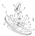
- Figure 1 illustrates an exploded view of a dual axle, four-cam unit, including one embodiment of a connection system according to the present invention
- Figure 2 illustrates a perspective view of the dual axle, four-cam unit shown in Figure 1 in an expanded configuration
- Figure 3 illustrates a perspective view of the dual axle, four-cam unit shown in Figure 1 in a retracted configuration
- Figure 4 illustrates a perspective view of an alternative embodiment of a connection system according to the present invention wherein the connection system includes two adjacent terminals;
- Figure 5 illustrates a perspective view of yet another alternative embodiment of a cable terminal according to the present invention wherein the cable terminal includes a lower member
- Figure 6 illustrates a perspective view of yet another alternative embodiment of a cable terminal according to the present invention wherein the cable is configured to attach to the cable terminal through a single hole;
- Figure 7 illustrates a perspective view of yet another alternative embodiment of a terminal member according to the present invention wherein a terminal member includes an integrated cable terminal and axle;
- Figure 8 illustrates a passive protection device incorporating a connection system according to the present invention.
- Figure 9 illustrates an alternative embodiment of a sling for use with an active camming device.
- a single stem connection system for use with an active protection device includes a single bent cable that is attached to the single cable terminal of the active protection device.
- a stem tube is fitted over a portion of the bent cable giving the appearance and benefits of a single stem.
- a portion of the bent cable is left separated thereby automatically forming a clip-in point for the entire active protection device.
- the single stem system in accordance with the present invention only requires coupling the cable to the cable terminal thereby reducing manufacturing cost and minimizing overall weight.
- a similar connection system can be used with a passive protection device to provide many of the same benefits.
- embodiments of the present invention are described in the context of a connection system for use with a protection device, and a method of manufacturing, it will be appreciated that the teachings of the present invention are applicable to other applications as well.
- FIG. 1 illustrates an exploded view of a dual axle, four-cam unit, including one embodiment of a connection system according to the present invention.
- the active protection device illustrated in Figure 1 is designated generally at 100.
- the active protection device includes a camming system, a retraction system, and a connection system.
- the illustrated camming system includes four cam lobes 150, two axles 175, two torsion springs 160, a cable terminal 135, and two axle connectors 165.
- the camming system is configured to actively cam against a protection surface.
- the middle of the axles 175 are positioned substantially within the two holes 141 of the cable terminal 135.
- the cam lobes 150, torsion springs 160, and axle connectors 165 are positioned on either side of the two axles 175 as shown in Figure 1. Two of the cam lobes are coupled to one axle 175 while the other two cam lobes 150 are coupled to the other axle.
- a cable terminal or terminal is defined broadly to include any means for coupling the axle and or the cam lobes to the stem portion of the device.
- the cam lobes 150 each include a fixed axle hole 154, an open axle area 155, a trigger hole 152, and a body 156.
- the torsion springs 160 are each coupled to a single cam lobe 150 and an adjacent torsion spring 160 as shown in Figure 1. This configuration results in biasing the cam lobes 150 in an extended position.
- the cam lobes 150 are prevented from over rotating through the use of the dual axle design and more specifically the open axle areas 155 abutting against the axles 175.
- cam stops would need to be included on the cam lobes to prevent them from over-rotating.
- the axle connectors 165 are positioned on the outer edges of the axles 175 to prevent the cam lobes 150 from sliding off the axles 175.
- compression springs, extension springs, leaf springs, or a compliant mechanism could be used to bias the cam lobes 150 in the extended position.
- the illustrated embodiment shows two axles 175, it should be noted that the teachings of the present invention can be utilized with any number of axles and remain consistent with the present invention.
- the retraction system includes the various components to retract the cam lobes 150 into a retracted position.
- the retraction system includes a trigger 125 and four trigger wires 170.
- the trigger 125 further includes two trigger wire holes 129, a stem hole 128, and a body 127.
- the trigger 125 is configured to be slidable with respect to the stem such that a user can retract the trigger away from the cable terminal 135.
- the trigger 125 is independently coupled to each of the cam lobes 150 via the trigger wires 170.
- the trigger wires 170 hook into the trigger holes 152 in the cam lobes 150 and the trigger wire holes 129 on the trigger 125.
- the distance between the trigger and the cable terminal 135 must be precisely measured in order to maintain proper retraction ergonomics while minimizing overall device weight. For example, if the distance between the trigger 125 and cable terminal 135 is too short, it is possible for the cam lobes 150 to touch or rub a user's hand during retraction. Likewise, if the distance between the trigger 125 and the cable terminal 135 is too long, the device includes unnecessary weight. Therefore, the trigger 125 must be optimally positioned a particular distance from the cable terminal 135.
- the trigger 125 can be positioned even closer to the cable terminal 135 without risking contact between a user's hand and the cam lobes 150 during retraction.
- connection system is designed to provide a system by which a user can connect the camming system to a rope or other device.
- the connection system in accordance with the embodiment illustrated in Figure 1 includes a single cable terminal 135, a stem tube 130, a thumb rest 120, a cable cover 105, a cable 115, and a connection sling 110.
- the illustrated embodiments show the cable 115 being oriented parallel to the axle, it should be noted that the cable could be oriented perpendicular or in any other orientation with respect to the axle and remain consistent with the present invention.
- the connection system of the present invention is unique in that it creates the appearance of a single stem and automatically forms a clip-in point for a user.
- connection system minimizes the amount of connections or swages by using a single cable 115 and a single terminal 135.
- the cable 115 extends through the cable cover 105 at a median point on the cable 115 which will form the clip-in point.
- the cable cover 105 prevents external devices from contacting the cable 115.
- a connection sling 110 is also coupled to the cable cover 105 to provide an auxiliary clip-in point.
- the connection sling 110 could be doubled around the cable cover 105, as described in more detail with reference to Figure 9, to increases the force necessary to cut the connection sling 105 on the cable cover 105 and cable 115.
- connection sling 110 may also be used for the connection sling 110 to increase the force necessary to cut the connection sling 105 on the cable cover 105 and the cable 115.
- the cable 115 extends through the thumb rest 120 and stem tube 130 as shown in Figure 1.
- the stem tube 130 compresses the two halves of the wire up against one another giving the appearance of a single stem.
- the thumb rest 120 assists in transitioning the cable 115 from the separated or clip-in portion to the compressed or single-stem portion.
- the thumb rest 120 also provides a location for a user to apply an opposing force when retracting the trigger 125.
- the ends of the cable 115 that extend through the stem tube 130 are extended through cable hole 137 in the cable terminal 135 and coupled to the ball wedge 145 at a single connection point.
- the ball wedge 145 is shaped in a substantially conical configuration to prevent being extended back through the cable hole 137 of the cable terminal 135.
- the coupling between the cable 115 and the ball wedge 145 includes but is not limited to a compression swage or a heated solder coupling.
- other embodiments of a connection system in accordance with the present invention are described with reference to Figures 4-7.
- connection system illustrated in Figure 1 has many benefits over those found in conventional active protection devices. Minimizing the cable's 115 gauge or thickness and the number of cable 115 connections or couplings effectively minimize the overall weight of the connection system.
- Conventional single stem connection systems utilize a heavier gauge wire and multiple wire connection points. The thickness or gauge of the wire and the number of connection points dramatically affects the overall weight of an active protection device.
- dual stem active protection devices include multiple cable terminals and therefore multiple cable connection points also resulting in additional weight.
- Figures 2 and 3 illustrate perspective views of the dual axle, four-cam unit shown in Figure 1 in an expanded and retracted configurations respectively.
- the cam lobes 150 can be positioned in either an expanded or retracted position.
- the expanded position shown in Figure 2 results from no force being applied to the trigger 125 thereby allowing the torsion springs to bias the cam lobes 150 into the extended position.
- a retraction force 180 is applied to the trigger 125 and a stabilizing force 180 is applied to the thumb rest
- the cam lobes 150 are retracted into the retracted position as shown in Figure 3.
- the retraction force 180 applied to the trigger 125 causes the trigger wires 170 to retract or rotate the cam lobes 150 as shown.
- the torsion springs 160 will cause the cam lobes 150 to automatically return to the expanded configuration shown in Figure 2.
- FIG 4 illustrates an alternative embodiment of a connection system according to the present invention wherein the connection system includes two adjacent terminals.
- the active protection device 200 illustrated in Figure 4 is incomplete for the purpose of illustrating an alternative connection system in accordance with the present invention.
- the alternative connection system includes a cable 215, a stem tube 230, a thumb rest 220, a cable cover 205, and two cable terminals 235, 240.
- the two cable terminals 235, 240 are positioned adjacent and substantially coupled to one another as shown in Figure 4.
- the cable 215 is extended through the cable cover 205, thumb rest 220, and stem tube 230 in the same manner as described with reference to the connection system illustrated in Figure 1.
- FIG. 5 illustrates yet another alternative embodiment of a cable terminal according to the present invention wherein the cable terminal includes a lower member.
- the cable terminal 300 illustrated in Figure 5 is only a portion of a connection system but is configured such that it could be substituted into the active protection device 100 illustrated in Figure 1.
- the cable terminal 335 includes a top portion 339, two axle holes 341, and a lower member 343.
- the cable 315 only extends into the lower member 343 of the cable terminal 300 as shown in phantom.
- the cable 315 is coupled to the lower member 343 with a coupling system including but not limited to swaging or soldering. This embodiment may be particularly useful for very small active protection devices wherein the necessary spacing between the axle holes 341 does not allow for the cable 315 to be extended all the way through the cable terminal 335.
- FIG. 6 illustrates yet another alternative embodiment of a cable terminal according to the present invention wherein the cable is configured to attach to the cable terminal through a single hole.
- the cable terminal 400 illustrated in Figure 6 is only a portion of a connection system but is configured such that it could be substituted into the active protection device 100 illustrated in Figure 1.
- the cable terminal 435 includes a body 439 and two axle holes 441.
- the cable 415 is able to extend all the way through the cable terminal 435 similar to the embodiment shown in Figures 1-3. However, the ends of the cable 415 are swaged directly to the cable terminal 435 rather than to a ball wedge.
- This embodiment is particularly useful for large active camming units where there is sufficient space between the axle holes 441 to extend the cable 415 between the axles holes 441 and swage it to the cable terminal 435.
- FIG. 7 illustrates yet another alternative embodiment of a terminal member according to the present invention wherein a terminal member includes an integrated cable terminal and axle.
- the terminal member 500 illustrated in Figure 7 is only a portion of a connection system but is configured such that it could be substituted into a single axle active protection device.
- the terminal member 500 includes an axle portion 575 disposed on the outer portion and a terminal portion 540 disposed on the middle portion of the terminal member 500.
- the terminal portion includes a cable terminal 539 and two cable receiving holes 545.
- the cable 515 is coupled to the terminal member 500 either directly (as discussed with reference to Figure 6) or externally (as discussed with reference to Figures 1-4).
- the axle portion 575 can be configured to conform to the size requirements necessary to accommodate any type of cam lobe.
- the terminal member 500 embodiment illustrated in Figure 7 is particularly useful for small single axle active protection devices.
- the passive protection device 600 illustrated in Figure 8 is a standard wedge chock but the connection system in accordance with the present invention could be used with any type of passive protection device.
- the passive protection device 600 includes a camming head 620 and a cable 615.
- the camming head 620 is shaped and tapered to passively cam into one or more particularly sized tapers.
- the camming head includes a body 625 and a recess 630 that extends through the body 625.
- the cable 615 is coupled to the camming head 620 by extending into the single recess 630 and directly coupling to the camming head 620.
- the coupling technique between the camming head 620 and the cable 615 includes but is not limited to swaging or soldering.
- the cable 615 could extend through the camming head 620 and be coupled to an external member such as a ball wedge.
- Figure 9 illustrates an alternative embodiment of a sling 110 for use with an active camming device.
- the illustrated sling 110 configuration increases the force required for the cable 115 to cut through the sling.
- the area around the cable 115 is effectively doubled.
- the stitching configuration of the sling allows for the entire length of the sling to be usable rather than a portion.
- the stitching configuration naturally biases the sling in an open position allowing for easy clipping and grabbing.
Landscapes
- Health & Medical Sciences (AREA)
- Pulmonology (AREA)
- General Health & Medical Sciences (AREA)
- Physical Education & Sports Medicine (AREA)
- Clamps And Clips (AREA)
- Flexible Shafts (AREA)
- Mutual Connection Of Rods And Tubes (AREA)
- Electrophotography Configuration And Component (AREA)
- Electric Cable Installation (AREA)
- Mounting, Exchange, And Manufacturing Of Dies (AREA)
- Earth Drilling (AREA)
Applications Claiming Priority (2)
| Application Number | Priority Date | Filing Date | Title |
|---|---|---|---|
| US53840604P | 2004-01-22 | 2004-01-22 | |
| US538406P | 2004-01-22 |
Publications (2)
| Publication Number | Publication Date |
|---|---|
| EP1557202A1 true EP1557202A1 (de) | 2005-07-27 |
| EP1557202B1 EP1557202B1 (de) | 2011-05-04 |
Family
ID=34633025
Family Applications (1)
| Application Number | Title | Priority Date | Filing Date |
|---|---|---|---|
| EP05001127A Active EP1557202B1 (de) | 2004-01-22 | 2005-01-20 | Schutzvorrichtung für den Schaft eines Klemmkeils |
Country Status (5)
| Country | Link |
|---|---|
| US (2) | US7959118B2 (de) |
| EP (1) | EP1557202B1 (de) |
| AT (1) | ATE507888T1 (de) |
| DE (1) | DE602005027764D1 (de) |
| ES (1) | ES2366190T3 (de) |
Cited By (6)
| Publication number | Priority date | Publication date | Assignee | Title |
|---|---|---|---|---|
| ES2258940A1 (es) * | 2006-05-09 | 2006-09-01 | Aitzol Telleria Gabiria | Anclaje de seguridad para escalada. |
| KR200453694Y1 (ko) | 2009-04-06 | 2011-05-23 | 이춘심 | 암벽 등반용 캠 |
| EP2353664A1 (de) * | 2010-02-05 | 2011-08-10 | DMM International Ltd | Schutzvorrichtung zur Verwendung beim Klettern |
| EP2674200A3 (de) * | 2012-06-15 | 2014-09-10 | Black Diamond Equipment AG | Verbesserte Nockenvorrichtung |
| KR101439300B1 (ko) | 2013-12-13 | 2014-09-11 | 홍상권 | 암벽등반용 다이아몬드형 캠 |
| EP2853296A1 (de) * | 2013-09-26 | 2015-04-01 | DMM International Ltd | Schutzvorrichtung zur Verwendung beim Klettern |
Families Citing this family (14)
| Publication number | Priority date | Publication date | Assignee | Title |
|---|---|---|---|---|
| US7011281B2 (en) * | 2002-02-28 | 2006-03-14 | Karl Guthrie | Expansion bolt |
| US7357363B2 (en) * | 2003-12-30 | 2008-04-15 | Karl Guthrie | Expansion bolt |
| US20090056267A1 (en) * | 2007-07-12 | 2009-03-05 | Reeves Eric William | Expansible hole anchor |
| ES2366507B1 (es) * | 2008-09-26 | 2012-08-03 | Universidad De La Rioja | Dispositivo de progresión y aseguramiento para escalada y trabajos verticales. |
| US8317145B2 (en) * | 2009-04-17 | 2012-11-27 | Max William Reed | Spring loaded camming device with movably-anchored trigger |
| US9302154B2 (en) * | 2012-06-15 | 2016-04-05 | Black Diamond Equipment, Ltd. | Camming device stem |
| WO2014152150A1 (en) * | 2013-03-14 | 2014-09-25 | Cam-Keeper, Llc | Materials and methods for use with climbing cams |
| US9370692B2 (en) * | 2013-07-01 | 2016-06-21 | Nathanial James Czech | Active cam device |
| US10143892B2 (en) * | 2014-04-12 | 2018-12-04 | Black Diamond Equipment, Ltd. | Cam stem system |
| EP3302731A1 (de) * | 2015-06-05 | 2018-04-11 | Wild Country Limited | Nockenvorrichtung |
| US10463916B2 (en) | 2016-07-01 | 2019-11-05 | Erick Matthew Davidson | Active camming device |
| US10330256B2 (en) | 2016-12-08 | 2019-06-25 | Douglas Michael Eckhart | Column grip |
| WO2018182431A1 (en) * | 2017-03-28 | 2018-10-04 | Matthew Hall | Improvements in, or relating to, anchors for climbing and related activities |
| US11383136B2 (en) * | 2019-04-30 | 2022-07-12 | Black Diamond Equipment, Ltd. | Camming stem system |
Citations (6)
| Publication number | Priority date | Publication date | Assignee | Title |
|---|---|---|---|---|
| DE3517741A1 (de) * | 1985-05-17 | 1986-01-23 | Stefan 4370 Marl Engers | Kletterhilfe, insbesondere fuer bergsteiger |
| US4643377A (en) * | 1985-09-26 | 1987-02-17 | Tony Christianson | Mechanically expanding climbing aid |
| AT398167B (de) * | 1989-01-18 | 1994-10-25 | Prohaska Heinz | Kletter-klemmvorrichtung |
| US6119993A (en) * | 1996-12-18 | 2000-09-19 | Youngblood; Gary S. | Climbing anchors |
| US6283426B1 (en) * | 2000-02-04 | 2001-09-04 | Karl Guthrie | Spring-loaded camming nut |
| US20030019321A1 (en) * | 2001-06-28 | 2003-01-30 | Mikel Apezetxea | Cam device for climbing |
Family Cites Families (35)
| Publication number | Priority date | Publication date | Assignee | Title |
|---|---|---|---|---|
| US464337A (en) * | 1891-12-01 | Yarn-dyeing machine | ||
| US611999A (en) * | 1898-10-04 | Half to william t | ||
| US2903291A (en) * | 1957-02-14 | 1959-09-08 | Liftex Slings Inc | Fabric sling |
| US2985480A (en) * | 1958-02-10 | 1961-05-23 | John A Otley | Sling |
| US2979297A (en) * | 1959-05-20 | 1961-04-11 | Bergen Pipesupport Corp | Combined support and shock absorber for piping and the like |
| US3371663A (en) * | 1965-07-06 | 1968-03-05 | Martha M. Apgar | Arm sling |
| DE1900962A1 (de) * | 1968-01-10 | 1969-07-31 | Goeteborgs Bandvaeveri Aktiebo | Schlinge an Lasthebeeinrichtungen |
| USRE26704E (en) * | 1968-12-03 | 1969-11-04 | Norton fabric load lifting sling | |
| US3776585A (en) * | 1972-09-15 | 1973-12-04 | Lift All Co Inc | Synthetic fiber sling construction |
| US3877679A (en) * | 1973-08-16 | 1975-04-15 | Lowe Alpine Systems Inc | Anchor device for mountain climbers |
| US4044976A (en) * | 1974-05-17 | 1977-08-30 | Campbell Gaylord K | Chocks |
| GB1588317A (en) * | 1977-06-04 | 1981-04-23 | Jardine R D | Climbing aids |
| US4566342A (en) * | 1983-05-05 | 1986-01-28 | Kurz Jerome L | Isokinetic extractive sampling probe |
| US4526164A (en) * | 1983-07-11 | 1985-07-02 | Theodore A. Kirby | Universal size arm sling |
| US4572464A (en) * | 1983-10-17 | 1986-02-25 | Phillips Douglas D | Change-configuration climbing chock |
| US4565342A (en) * | 1984-07-12 | 1986-01-21 | Grow Robert D | Anchoring device for rock climbing |
| SE453631B (sv) * | 1985-02-18 | 1988-02-22 | Karner & Co Ab | Kjol- eller byxhengare |
| US4643378A (en) * | 1985-03-18 | 1987-02-17 | Karl Guthrie | Roller-chock climbing aid |
| US4575032A (en) * | 1985-04-04 | 1986-03-11 | Taylor Peter C | Rock climbing adjustable chock |
| US4645149A (en) * | 1985-09-04 | 1987-02-24 | Lowe Alpine Systems, Inc. | Camming device for climbers |
| GB2193902B (en) * | 1986-08-13 | 1990-05-02 | Hugh Irving Banner | Climbing aids |
| US4832289A (en) * | 1987-08-11 | 1989-05-23 | Waggoner David L | Anchoring device for use in crevices |
| US4923160A (en) * | 1988-12-02 | 1990-05-08 | Waggoner David L | Camming means for climbing anchors |
| US5617767A (en) * | 1995-11-29 | 1997-04-08 | Nikoden; James | Extractor tool |
| US5860629A (en) * | 1996-09-06 | 1999-01-19 | Reed; Max W. | Climbing aid having movable axle |
| US6042069A (en) * | 1998-08-03 | 2000-03-28 | Christianson; Tony | Expanding climbing aid |
| US6375139B1 (en) * | 2000-10-20 | 2002-04-23 | Seth Murray | Anchoring device for use in rock crevices and the like during rock climbing activities |
| GB0027869D0 (en) * | 2000-11-15 | 2000-12-27 | Dmm Engineering Ltd | Improvements in and relating to camming devices |
| US6736359B2 (en) * | 2001-07-05 | 2004-05-18 | Seth Murray | Anchoring device for use in rock crevices and the like during rock climbing activities |
| GB0118171D0 (en) * | 2001-07-26 | 2001-09-19 | Wild Country Ltd | Improvements in and relating to camming devices |
| US20040035992A1 (en) * | 2002-08-23 | 2004-02-26 | Watts Allan W. | Rock-anchoring devices with non-metal components |
| US20050037023A1 (en) * | 2003-08-12 | 2005-02-17 | Metolius Mountain Products, Inc. | Mechanical climbing aid of the cam type |
| US7040588B2 (en) * | 2003-11-12 | 2006-05-09 | Omega Pacific, Inc. | Anchor assembly |
| US20050218282A1 (en) * | 2004-03-30 | 2005-10-06 | Metolius Mountain Products, Inc. | Climbing cam placement indicator |
| CA2537289A1 (en) * | 2005-02-18 | 2006-08-18 | Scott Jacob Thumlert | Camming device for climbing and use thereof |
-
2004
- 2004-12-22 US US11/021,000 patent/US7959118B2/en active Active
-
2005
- 2005-01-20 ES ES05001127T patent/ES2366190T3/es active Active
- 2005-01-20 AT AT05001127T patent/ATE507888T1/de active
- 2005-01-20 EP EP05001127A patent/EP1557202B1/de active Active
- 2005-01-20 DE DE602005027764T patent/DE602005027764D1/de active Active
-
2008
- 2008-10-08 US US12/247,661 patent/US7959119B2/en active Active
Patent Citations (6)
| Publication number | Priority date | Publication date | Assignee | Title |
|---|---|---|---|---|
| DE3517741A1 (de) * | 1985-05-17 | 1986-01-23 | Stefan 4370 Marl Engers | Kletterhilfe, insbesondere fuer bergsteiger |
| US4643377A (en) * | 1985-09-26 | 1987-02-17 | Tony Christianson | Mechanically expanding climbing aid |
| AT398167B (de) * | 1989-01-18 | 1994-10-25 | Prohaska Heinz | Kletter-klemmvorrichtung |
| US6119993A (en) * | 1996-12-18 | 2000-09-19 | Youngblood; Gary S. | Climbing anchors |
| US6283426B1 (en) * | 2000-02-04 | 2001-09-04 | Karl Guthrie | Spring-loaded camming nut |
| US20030019321A1 (en) * | 2001-06-28 | 2003-01-30 | Mikel Apezetxea | Cam device for climbing |
Cited By (10)
| Publication number | Priority date | Publication date | Assignee | Title |
|---|---|---|---|---|
| ES2258940A1 (es) * | 2006-05-09 | 2006-09-01 | Aitzol Telleria Gabiria | Anclaje de seguridad para escalada. |
| KR200453694Y1 (ko) | 2009-04-06 | 2011-05-23 | 이춘심 | 암벽 등반용 캠 |
| EP2353664A1 (de) * | 2010-02-05 | 2011-08-10 | DMM International Ltd | Schutzvorrichtung zur Verwendung beim Klettern |
| EP2674200A3 (de) * | 2012-06-15 | 2014-09-10 | Black Diamond Equipment AG | Verbesserte Nockenvorrichtung |
| US9079065B2 (en) | 2012-06-15 | 2015-07-14 | Black Diamond Equipment Ltd. | Camming device |
| EP2853296A1 (de) * | 2013-09-26 | 2015-04-01 | DMM International Ltd | Schutzvorrichtung zur Verwendung beim Klettern |
| EP2954937A1 (de) * | 2013-09-26 | 2015-12-16 | DMM International Ltd | Schutzvorrichtung zur verwendung beim klettern |
| KR101439300B1 (ko) | 2013-12-13 | 2014-09-11 | 홍상권 | 암벽등반용 다이아몬드형 캠 |
| WO2015088169A1 (ko) * | 2013-12-13 | 2015-06-18 | 홍슬민 | 암벽등반용 다이아몬드형 캠 |
| US9636544B2 (en) | 2013-12-13 | 2017-05-02 | Seul-Min Hong | Diamond type cam for rock climbing |
Also Published As
| Publication number | Publication date |
|---|---|
| US20090045307A1 (en) | 2009-02-19 |
| US7959118B2 (en) | 2011-06-14 |
| ATE507888T1 (de) | 2011-05-15 |
| DE602005027764D1 (de) | 2011-06-16 |
| EP1557202B1 (de) | 2011-05-04 |
| US7959119B2 (en) | 2011-06-14 |
| ES2366190T3 (es) | 2011-10-18 |
| US20050161565A1 (en) | 2005-07-28 |
Similar Documents
| Publication | Publication Date | Title |
|---|---|---|
| EP1557202A1 (de) | Schutzvorrichtung für den Schaft eines Klemmkeils | |
| EP1557201B1 (de) | Verbesserter Klemmkeil | |
| EP2674201B1 (de) | Verbesserter Stiel eines Klemmgeräts | |
| US10463916B2 (en) | Active camming device | |
| US10232199B2 (en) | Integral safety harness connector assembly | |
| CN106794367B (zh) | 安全带具 | |
| ES2286451T3 (es) | Fiador de tipo engarce con ranuras de bloqueo y crestas optimizadas, y metodo para diseñarlo. | |
| US20100124837A1 (en) | Backshell coupling for an electrical component | |
| US4832289A (en) | Anchoring device for use in crevices | |
| EP2929916A1 (de) | Verbessertes nockenschaftsystem | |
| US4811921A (en) | Cyclic control stick | |
| US20100317944A1 (en) | Rocker-Chute Type Finger-Clipped Oximeter | |
| US9370692B2 (en) | Active cam device | |
| US20200206549A1 (en) | Fall arresting device connector | |
| US20210001181A1 (en) | Camming stem system | |
| US7014156B2 (en) | Cam device for climbing | |
| US20060054386A1 (en) | Connector for a safety cable | |
| US6467573B1 (en) | Fall protection assembly | |
| GB2380949A (en) | Camming device | |
| EP1557200B1 (de) | Verbesserte aktive Klemmvorrichtungsoberfläche | |
| EP2674200A2 (de) | Verbesserte Nockenvorrichtung | |
| US11059595B2 (en) | Device to orient a riser of a parachute | |
| USD475813S1 (en) | Pair of protective shoulder pads | |
| EP2853296B1 (de) | Schutzvorrichtung zur Verwendung beim Klettern | |
| CN206770337U (zh) | 一种快速拆分机构以及吸盘 |
Legal Events
| Date | Code | Title | Description |
|---|---|---|---|
| PUAI | Public reference made under article 153(3) epc to a published international application that has entered the european phase |
Free format text: ORIGINAL CODE: 0009012 |
|
| AK | Designated contracting states |
Kind code of ref document: A1 Designated state(s): AT BE BG CH CY CZ DE DK EE ES FI FR GB GR HU IE IS IT LI LT LU MC NL PL PT RO SE SI SK TR |
|
| AX | Request for extension of the european patent |
Extension state: AL BA HR LV MK YU |
|
| 17P | Request for examination filed |
Effective date: 20060127 |
|
| AKX | Designation fees paid |
Designated state(s): AT BE BG CH CY CZ DE DK EE ES FI FR GB GR HU IE IS IT LI LT LU MC NL PL PT RO SE SI SK TR |
|
| 17Q | First examination report despatched |
Effective date: 20061227 |
|
| GRAP | Despatch of communication of intention to grant a patent |
Free format text: ORIGINAL CODE: EPIDOSNIGR1 |
|
| GRAS | Grant fee paid |
Free format text: ORIGINAL CODE: EPIDOSNIGR3 |
|
| GRAA | (expected) grant |
Free format text: ORIGINAL CODE: 0009210 |
|
| AK | Designated contracting states |
Kind code of ref document: B1 Designated state(s): AT BE BG CH CY CZ DE DK EE ES FI FR GB GR HU IE IS IT LI LT LU MC NL PL PT RO SE SI SK TR |
|
| REG | Reference to a national code |
Ref country code: GB Ref legal event code: FG4D |
|
| REG | Reference to a national code |
Ref country code: CH Ref legal event code: EP |
|
| REG | Reference to a national code |
Ref country code: IE Ref legal event code: FG4D |
|
| REF | Corresponds to: |
Ref document number: 602005027764 Country of ref document: DE Date of ref document: 20110616 Kind code of ref document: P |
|
| REG | Reference to a national code |
Ref country code: DE Ref legal event code: R096 Ref document number: 602005027764 Country of ref document: DE Effective date: 20110616 |
|
| REG | Reference to a national code |
Ref country code: CH Ref legal event code: NV Representative=s name: BRAUNPAT BRAUN EDER AG |
|
| REG | Reference to a national code |
Ref country code: NL Ref legal event code: VDEP Effective date: 20110504 |
|
| REG | Reference to a national code |
Ref country code: ES Ref legal event code: FG2A Ref document number: 2366190 Country of ref document: ES Kind code of ref document: T3 Effective date: 20111018 |
|
| PG25 | Lapsed in a contracting state [announced via postgrant information from national office to epo] |
Ref country code: PT Free format text: LAPSE BECAUSE OF FAILURE TO SUBMIT A TRANSLATION OF THE DESCRIPTION OR TO PAY THE FEE WITHIN THE PRESCRIBED TIME-LIMIT Effective date: 20110905 Ref country code: SE Free format text: LAPSE BECAUSE OF FAILURE TO SUBMIT A TRANSLATION OF THE DESCRIPTION OR TO PAY THE FEE WITHIN THE PRESCRIBED TIME-LIMIT Effective date: 20110504 Ref country code: LT Free format text: LAPSE BECAUSE OF FAILURE TO SUBMIT A TRANSLATION OF THE DESCRIPTION OR TO PAY THE FEE WITHIN THE PRESCRIBED TIME-LIMIT Effective date: 20110504 |
|
| PG25 | Lapsed in a contracting state [announced via postgrant information from national office to epo] |
Ref country code: SI Free format text: LAPSE BECAUSE OF FAILURE TO SUBMIT A TRANSLATION OF THE DESCRIPTION OR TO PAY THE FEE WITHIN THE PRESCRIBED TIME-LIMIT Effective date: 20110504 Ref country code: GR Free format text: LAPSE BECAUSE OF FAILURE TO SUBMIT A TRANSLATION OF THE DESCRIPTION OR TO PAY THE FEE WITHIN THE PRESCRIBED TIME-LIMIT Effective date: 20110805 Ref country code: CY Free format text: LAPSE BECAUSE OF FAILURE TO SUBMIT A TRANSLATION OF THE DESCRIPTION OR TO PAY THE FEE WITHIN THE PRESCRIBED TIME-LIMIT Effective date: 20110504 Ref country code: IS Free format text: LAPSE BECAUSE OF FAILURE TO SUBMIT A TRANSLATION OF THE DESCRIPTION OR TO PAY THE FEE WITHIN THE PRESCRIBED TIME-LIMIT Effective date: 20110904 Ref country code: FI Free format text: LAPSE BECAUSE OF FAILURE TO SUBMIT A TRANSLATION OF THE DESCRIPTION OR TO PAY THE FEE WITHIN THE PRESCRIBED TIME-LIMIT Effective date: 20110504 Ref country code: BE Free format text: LAPSE BECAUSE OF FAILURE TO SUBMIT A TRANSLATION OF THE DESCRIPTION OR TO PAY THE FEE WITHIN THE PRESCRIBED TIME-LIMIT Effective date: 20110504 |
|
| PG25 | Lapsed in a contracting state [announced via postgrant information from national office to epo] |
Ref country code: NL Free format text: LAPSE BECAUSE OF FAILURE TO SUBMIT A TRANSLATION OF THE DESCRIPTION OR TO PAY THE FEE WITHIN THE PRESCRIBED TIME-LIMIT Effective date: 20110504 |
|
| PG25 | Lapsed in a contracting state [announced via postgrant information from national office to epo] |
Ref country code: EE Free format text: LAPSE BECAUSE OF FAILURE TO SUBMIT A TRANSLATION OF THE DESCRIPTION OR TO PAY THE FEE WITHIN THE PRESCRIBED TIME-LIMIT Effective date: 20110504 |
|
| PG25 | Lapsed in a contracting state [announced via postgrant information from national office to epo] |
Ref country code: PL Free format text: LAPSE BECAUSE OF FAILURE TO SUBMIT A TRANSLATION OF THE DESCRIPTION OR TO PAY THE FEE WITHIN THE PRESCRIBED TIME-LIMIT Effective date: 20110504 Ref country code: RO Free format text: LAPSE BECAUSE OF FAILURE TO SUBMIT A TRANSLATION OF THE DESCRIPTION OR TO PAY THE FEE WITHIN THE PRESCRIBED TIME-LIMIT Effective date: 20110504 Ref country code: SK Free format text: LAPSE BECAUSE OF FAILURE TO SUBMIT A TRANSLATION OF THE DESCRIPTION OR TO PAY THE FEE WITHIN THE PRESCRIBED TIME-LIMIT Effective date: 20110504 Ref country code: DK Free format text: LAPSE BECAUSE OF FAILURE TO SUBMIT A TRANSLATION OF THE DESCRIPTION OR TO PAY THE FEE WITHIN THE PRESCRIBED TIME-LIMIT Effective date: 20110504 |
|
| PLBE | No opposition filed within time limit |
Free format text: ORIGINAL CODE: 0009261 |
|
| STAA | Information on the status of an ep patent application or granted ep patent |
Free format text: STATUS: NO OPPOSITION FILED WITHIN TIME LIMIT |
|
| 26N | No opposition filed |
Effective date: 20120207 |
|
| REG | Reference to a national code |
Ref country code: DE Ref legal event code: R097 Ref document number: 602005027764 Country of ref document: DE Effective date: 20120207 |
|
| PG25 | Lapsed in a contracting state [announced via postgrant information from national office to epo] |
Ref country code: MC Free format text: LAPSE BECAUSE OF NON-PAYMENT OF DUE FEES Effective date: 20120131 |
|
| REG | Reference to a national code |
Ref country code: IE Ref legal event code: MM4A |
|
| PG25 | Lapsed in a contracting state [announced via postgrant information from national office to epo] |
Ref country code: IE Free format text: LAPSE BECAUSE OF NON-PAYMENT OF DUE FEES Effective date: 20120120 |
|
| PG25 | Lapsed in a contracting state [announced via postgrant information from national office to epo] |
Ref country code: BG Free format text: LAPSE BECAUSE OF FAILURE TO SUBMIT A TRANSLATION OF THE DESCRIPTION OR TO PAY THE FEE WITHIN THE PRESCRIBED TIME-LIMIT Effective date: 20110804 |
|
| PG25 | Lapsed in a contracting state [announced via postgrant information from national office to epo] |
Ref country code: TR Free format text: LAPSE BECAUSE OF FAILURE TO SUBMIT A TRANSLATION OF THE DESCRIPTION OR TO PAY THE FEE WITHIN THE PRESCRIBED TIME-LIMIT Effective date: 20110504 |
|
| PG25 | Lapsed in a contracting state [announced via postgrant information from national office to epo] |
Ref country code: LU Free format text: LAPSE BECAUSE OF NON-PAYMENT OF DUE FEES Effective date: 20120120 |
|
| PG25 | Lapsed in a contracting state [announced via postgrant information from national office to epo] |
Ref country code: HU Free format text: LAPSE BECAUSE OF FAILURE TO SUBMIT A TRANSLATION OF THE DESCRIPTION OR TO PAY THE FEE WITHIN THE PRESCRIBED TIME-LIMIT Effective date: 20050120 |
|
| REG | Reference to a national code |
Ref country code: FR Ref legal event code: PLFP Year of fee payment: 11 |
|
| PGFP | Annual fee paid to national office [announced via postgrant information from national office to epo] |
Ref country code: CZ Payment date: 20150105 Year of fee payment: 11 |
|
| REG | Reference to a national code |
Ref country code: DE Ref legal event code: R082 Ref document number: 602005027764 Country of ref document: DE Representative=s name: GRAMM, LINS & PARTNER PATENT- UND RECHTSANWAEL, DE |
|
| REG | Reference to a national code |
Ref country code: FR Ref legal event code: PLFP Year of fee payment: 12 |
|
| PGFP | Annual fee paid to national office [announced via postgrant information from national office to epo] |
Ref country code: CH Payment date: 20160127 Year of fee payment: 12 |
|
| PGFP | Annual fee paid to national office [announced via postgrant information from national office to epo] |
Ref country code: AT Payment date: 20160112 Year of fee payment: 12 |
|
| PG25 | Lapsed in a contracting state [announced via postgrant information from national office to epo] |
Ref country code: CZ Free format text: LAPSE BECAUSE OF NON-PAYMENT OF DUE FEES Effective date: 20160120 |
|
| REG | Reference to a national code |
Ref country code: FR Ref legal event code: PLFP Year of fee payment: 13 |
|
| REG | Reference to a national code |
Ref country code: CH Ref legal event code: PL |
|
| REG | Reference to a national code |
Ref country code: AT Ref legal event code: MM01 Ref document number: 507888 Country of ref document: AT Kind code of ref document: T Effective date: 20170120 |
|
| PG25 | Lapsed in a contracting state [announced via postgrant information from national office to epo] |
Ref country code: LI Free format text: LAPSE BECAUSE OF NON-PAYMENT OF DUE FEES Effective date: 20170131 Ref country code: AT Free format text: LAPSE BECAUSE OF NON-PAYMENT OF DUE FEES Effective date: 20170120 Ref country code: CH Free format text: LAPSE BECAUSE OF NON-PAYMENT OF DUE FEES Effective date: 20170131 |
|
| REG | Reference to a national code |
Ref country code: FR Ref legal event code: PLFP Year of fee payment: 14 |
|
| P01 | Opt-out of the competence of the unified patent court (upc) registered |
Effective date: 20230530 |
|
| PGFP | Annual fee paid to national office [announced via postgrant information from national office to epo] |
Ref country code: ES Payment date: 20240223 Year of fee payment: 20 |
|
| PGFP | Annual fee paid to national office [announced via postgrant information from national office to epo] |
Ref country code: DE Payment date: 20240119 Year of fee payment: 20 Ref country code: GB Payment date: 20240123 Year of fee payment: 20 |
|
| PGFP | Annual fee paid to national office [announced via postgrant information from national office to epo] |
Ref country code: IT Payment date: 20240129 Year of fee payment: 20 Ref country code: FR Payment date: 20240124 Year of fee payment: 20 |