EP1557147A2 - Zusammenlegbarer Rollstuhlrahmen - Google Patents
Zusammenlegbarer Rollstuhlrahmen Download PDFInfo
- Publication number
- EP1557147A2 EP1557147A2 EP05000355A EP05000355A EP1557147A2 EP 1557147 A2 EP1557147 A2 EP 1557147A2 EP 05000355 A EP05000355 A EP 05000355A EP 05000355 A EP05000355 A EP 05000355A EP 1557147 A2 EP1557147 A2 EP 1557147A2
- Authority
- EP
- European Patent Office
- Prior art keywords
- tube
- wheelchair frame
- side frame
- wheelchair
- scissors
- Prior art date
- Legal status (The legal status is an assumption and is not a legal conclusion. Google has not performed a legal analysis and makes no representation as to the accuracy of the status listed.)
- Granted
Links
Images


Classifications
-
- A—HUMAN NECESSITIES
- A61—MEDICAL OR VETERINARY SCIENCE; HYGIENE
- A61G—TRANSPORT, PERSONAL CONVEYANCES, OR ACCOMMODATION SPECIALLY ADAPTED FOR PATIENTS OR DISABLED PERSONS; OPERATING TABLES OR CHAIRS; CHAIRS FOR DENTISTRY; FUNERAL DEVICES
- A61G5/00—Chairs or personal conveyances specially adapted for patients or disabled persons, e.g. wheelchairs
- A61G5/08—Chairs or personal conveyances specially adapted for patients or disabled persons, e.g. wheelchairs foldable
- A61G5/0808—Chairs or personal conveyances specially adapted for patients or disabled persons, e.g. wheelchairs foldable characterised by a particular folding direction
- A61G5/0816—Chairs or personal conveyances specially adapted for patients or disabled persons, e.g. wheelchairs foldable characterised by a particular folding direction folding side to side, e.g. reducing or expanding the overall width of the wheelchair
- A61G5/0825—Chairs or personal conveyances specially adapted for patients or disabled persons, e.g. wheelchairs foldable characterised by a particular folding direction folding side to side, e.g. reducing or expanding the overall width of the wheelchair comprising a scissor-type frame, e.g. having pivoting cross bars for enabling folding
Definitions
- the invention relates to a collapsible wheelchair frame according to the preamble of the main claim.
- the invention relates to a collapsible Wheelchair frame with right and left side frames, which for folding the wheelchair together can be approximated.
- the two side frames are using a scissors kept in working condition.
- Scissors are also known in the art, they comprise two mutually articulated scissor arms, each rotatably mounted on the lower tubes of the side frames while the upper ends of the scissor frames are attached to the Upper tubes of the side frame can be latched.
- auxiliary scissors are the two scissor arms of Scissors kept in working condition of the wheelchair frame or tense.
- the invention is based on the object, a wheelchair frame to create the type mentioned, which is easier, cheaper Manufacturability a high degree of operational safety having.
- the solution according to the invention is characterized by a number of significant Advantages.
- connection of the scissor arm with the first bearing part can for example, by soldering or by welding.
- the wheelchair according to the invention comprises a right side frame 1 and a left side frame 2.
- the side frames each include a down tube 5 and a parallel to this, also in the substantially horizontally arranged top tube 9. These are each connected to a front front tube 10. At its rear end, a back tube 11 is provided.
- the construction of the side frames will be in conjunction with the Figures 3 to 9 described in detail.
- a pair of scissors 4 is provided, which mutually pivotable scissor arms 3 and an auxiliary scissors 13 includes.
- the mode of action and construction of the scissors 4 is basically known from the prior art, so that omitted a detailed description at this point can be.
- the wheelchair further includes a only schematically illustrated Seat 17 and a backrest 18. At the extended Back tubes 11 push handles 19 are formed.
- the reference numeral 20 generally designates a side support, which with an armrest and a protective cover is provided.
- a first bearing part 6 is formed, which is substantially semi-cylindrical is and is connected to the scissor arm 3.
- a second bearing part 7 is connectable.
- the connection is preferably done by a clip connection, so to be dispensed with further tools or the like can.
- a slip bowl 8 is inserted, which also has two parts can be trained.
- the sliding shell 8 in one piece form in the manner of a slotted tube and overshoot over the down tube 5 accordingly.
- the scissors 3 is held by retaining rings 21, which are attached or can be clipped (two-piece or one-piece made of elastic material).
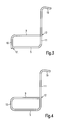
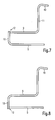
- FIGS. 3 to 9 show different variants of themselves According to the invention resulting side frame structures.
- Fig. 3 result in two joints 12, wherein the top tube. 9 and the front tube 10 are integrally formed with each other.
- Die Fig. 4 shows a preferred embodiment in which only a single joint 12 is provided, as the individual pipe sections each integrally formed with each other are.
- Fig. 5 In the embodiment of Fig. 5 are two joints 12 provided to insert the top tube 9.
- FIG. 6 also requires two joints 12, wherein the top tube 9, the front tube 10 and the Down tube 5 are integrally formed with each other.
- FIGS. 7 and 8 are a respective Joint 12 provided, the end of the down tube 5 is but free before.
- a Traverse or strut used and preferably screwed become. It is understood that in the embodiments FIGS. 7 and 8 also a one-piece design all pipe sections is possible, so on the joint 12 can be waived.
- Fig. 9 shows an embodiment with four joints.
- the attachment of the rear wheel on a Additional element done which, for example, with appropriate Frame is bolted.
- An inventive Wheelchair frame needed as a standard wheelchair or as Folding wheelchair usually no adjustment of the rear wheel (Driving wheel). If necessary, an adaptation to different Seat heights or seat depths by changing the dimensioning the side frame tubes done.
Landscapes
- Life Sciences & Earth Sciences (AREA)
- Animal Behavior & Ethology (AREA)
- General Health & Medical Sciences (AREA)
- Public Health (AREA)
- Veterinary Medicine (AREA)
- Health & Medical Sciences (AREA)
- Carriages For Children, Sleds, And Other Hand-Operated Vehicles (AREA)
- Mutual Connection Of Rods And Tubes (AREA)
- Other Liquid Machine Or Engine Such As Wave Power Use (AREA)
- Handcart (AREA)
- Fittings On The Vehicle Exterior For Carrying Loads, And Devices For Holding Or Mounting Articles (AREA)
- Tents Or Canopies (AREA)
- Passenger Equipment (AREA)
- Management, Administration, Business Operations System, And Electronic Commerce (AREA)
- Devices For Medical Bathing And Washing (AREA)
Abstract
Description
- Fig. 1
- eine vereinfachte schematische perspektivische Ansicht eines erfindungsgemäßen Rollstuhls,
- Fig. 2
- eine vergrößerte Darstellung der Lagerung des Scherenarms an dem Unterrohr,
- Fig. 3 bis 9
- verschiedene Ausgestaltungsvarianten (in Seitenansicht) der erfindungsgemäß verwendbaren Seitenrahmen.
- 1
- Rechter Seitenrahmen
- 2
- Linker Seitenrahmen
- 3
- Scherenarm
- 4
- Schere
- 5
- Unterrohr
- 6
- Erstes Lagerteil
- 7
- Zweites Lagerteil
- 8
- Gleitschale
- 9
- Oberrohr
- 10
- Vorderrohr
- 11
- Rückenrohr
- 12
- Fügestelle
- 13
- Hilfsschere
- 14
- Bremse
- 15
- Hinterrad
- 16
- Vorderrad
- 17
- Sitz
- 18
- Rückenlehne
- 19
- Schiebegriff
- 20
- Armstütze
- 21
- Haltering
Claims (7)
- Zusammenlegbarer Rollstuhlrahmen mit einem rechten (1) und einem linken (2) Seitenrahmen, sowie mit einer diese verbindende, zwei Scherenarme (3) umfassenden Schere (4), welche jeweils an einem Unterrohr (5) des Seitenrahmens (1, 2) gelagert ist, dadurch gekennzeichnet, dass an dem Endbereich des Scherenarms (3) ein erstes, im Wesentlichen halbzylindrisches Lagerteil (6) befestigt ist, welches formschlüssig mit einem einclipsbaren, im Wesentlichen halbzylindrischen zweiten Lagerteil (7) verbunden ist.
- Rollstuhlrahmen nach Anspruch 1, dadurch gekennzeichnet, dass die Lagerteile (6, 7) ineinanderclipsbar sind.
- Rollstuhlrahmen nach Anspruch 1 oder 2, dadurch gekennzeichnet, dass zwischen dem Unterrohr (5) und den Lagerteilen (6, 7) zumindest eine Gleitschale (8) eingesetzt ist.
- Rollstuhlrahmen nach Anspruch 1 bis 3, dadurch gekennzeichnet, dass der Seitenrahmen (1, 2) ein zu dem Unterrohr (5) paralleles Oberrohr (9) umfasst, welche beide im Wesentlichen horizontal angeordnet sind.
- Rollstuhlrahmen nach Anspruch 4, dadurch gekennzeichnet, dass das Unterrohr (5) und das Oberrohr (9) mittels eines vertikalen Vorderrohres (10) und eines Rückenrohres (11) verbunden sind.
- Rollstuhlrahmen nach Anspruch 5, dadurch gekennzeichnet, dass die Rohre (5, 9, 10, 11) des Seitenrahmens mittels nur einer Fügestelle (12) verbunden sind.
- Rollstuhlrahmen nach Anspruch 5, dadurch gekennzeichnet, dass die Rohre (5, 9, 10, 11) des Seitenrahmens mittels nur zwei Fügestellen (12) miteinander verbunden sind.
Applications Claiming Priority (2)
| Application Number | Priority Date | Filing Date | Title |
|---|---|---|---|
| DE202004001121U DE202004001121U1 (de) | 2004-01-26 | 2004-01-26 | Zusammenlegbarer Rollstuhlrahmen |
| DE202004001121U | 2004-01-26 |
Publications (3)
| Publication Number | Publication Date |
|---|---|
| EP1557147A2 true EP1557147A2 (de) | 2005-07-27 |
| EP1557147A3 EP1557147A3 (de) | 2005-12-21 |
| EP1557147B1 EP1557147B1 (de) | 2008-10-08 |
Family
ID=32115833
Family Applications (1)
| Application Number | Title | Priority Date | Filing Date |
|---|---|---|---|
| EP05000355A Expired - Lifetime EP1557147B1 (de) | 2004-01-26 | 2005-01-10 | Zusammenlegbarer Rollstuhlrahmen |
Country Status (4)
| Country | Link |
|---|---|
| EP (1) | EP1557147B1 (de) |
| AT (1) | ATE410127T1 (de) |
| DE (2) | DE202004001121U1 (de) |
| NO (1) | NO20050297L (de) |
Families Citing this family (2)
| Publication number | Priority date | Publication date | Assignee | Title |
|---|---|---|---|---|
| USD624459S1 (en) | 2006-11-08 | 2010-09-28 | Medline Industries, Inc. | Transport wheelchair |
| DE102009019344B4 (de) * | 2009-04-30 | 2011-01-20 | Otto Bock Mobility Solutions Gmbh | Rollstuhlrahmen |
Family Cites Families (4)
| Publication number | Priority date | Publication date | Assignee | Title |
|---|---|---|---|---|
| US4323133A (en) * | 1979-03-05 | 1982-04-06 | Williams Patrick Y | Folding frameworks and wheel-chairs |
| US4840390A (en) * | 1986-09-30 | 1989-06-20 | Invacare Corporation | Symmetrically modular wheelchair |
| US5263728A (en) * | 1991-08-05 | 1993-11-23 | Invacare Corporation | Low profile wheelchair |
| US5915709A (en) * | 1996-11-12 | 1999-06-29 | Invacare Corporation | Modular cross member assembly for adjustable wheelchair |
-
2004
- 2004-01-26 DE DE202004001121U patent/DE202004001121U1/de not_active Expired - Lifetime
-
2005
- 2005-01-10 DE DE502005005575T patent/DE502005005575D1/de not_active Expired - Lifetime
- 2005-01-10 AT AT05000355T patent/ATE410127T1/de not_active IP Right Cessation
- 2005-01-10 EP EP05000355A patent/EP1557147B1/de not_active Expired - Lifetime
- 2005-01-19 NO NO20050297A patent/NO20050297L/no not_active Application Discontinuation
Also Published As
| Publication number | Publication date |
|---|---|
| EP1557147B1 (de) | 2008-10-08 |
| NO20050297L (no) | 2005-07-27 |
| NO20050297D0 (no) | 2005-01-19 |
| DE502005005575D1 (de) | 2008-11-20 |
| DE202004001121U1 (de) | 2004-04-15 |
| EP1557147A3 (de) | 2005-12-21 |
| ATE410127T1 (de) | 2008-10-15 |
Similar Documents
| Publication | Publication Date | Title |
|---|---|---|
| DE2735939C2 (de) | Achsverbund für Kraftfahrzeuge, insbesondere PKW | |
| WO2013110528A1 (de) | Hilfsrahmen für ein kraftfahrzeug | |
| AT408215B (de) | Skibob | |
| EP0794106A2 (de) | Fahrschemel für eine gelenkte Achse eines Kraftfahrzeuges | |
| EP2360081A1 (de) | Fahrzeugkarosserieaufbau im Bereich zwischen Federbeinaufnahmen und Scheibenquerträger sowie zugeordnetes Fertigungsverfahren | |
| EP0827729A2 (de) | Rollstuhl | |
| EP0265675B1 (de) | Baueinheit aus einem Hilfsrahmen und schwenkbar daran angelenkten Radführungslenkern | |
| DE1580593B1 (de) | Hinterradaufhaengung fuer Kraftfahrzeuge | |
| DE69426991T2 (de) | Längsarmaufhängung | |
| DE2430048C3 (de) | Hinterachse, für Kraftfahrzeuge | |
| DE2425740B2 (de) | Hinterachse für Kraftfahrzeuge | |
| DE602004009938T2 (de) | Verformbarer längsträger für ein kraftfahrzeug | |
| DE966500C (de) | Elastische Verbindung eines Achsaggregattraegers von Fahrzeugen mit dem Rahmen oder Wagenkasten | |
| EP1557147B1 (de) | Zusammenlegbarer Rollstuhlrahmen | |
| DE19631975B4 (de) | Kraftfahrzeugachse | |
| DE2518711C3 (de) | Raupenfahrzeuggestell | |
| EP3068663B1 (de) | Lehnenversteller für einen fahrzeugsitz und fahrzeugsitz | |
| DE19941907A1 (de) | Vorderer Tragaufbau für ein Kraftfahrzeug | |
| DE10113136B4 (de) | Einklappbarer Tritt | |
| EP0940322A1 (de) | Fahrgestell eines schweren Nutzfahrzeuges | |
| DE1755620B2 (de) | Hinterradaufhaengung fuer kraftfahrzeuge | |
| DE102011053733A1 (de) | Fahrradrahmen aus stranggepresstem Hohlprofil | |
| DE588121C (de) | Antriebsvorrichtung fuer Stossdaempfer an Kraftfahrzeugen | |
| EP1516608B1 (de) | Rollstuhlrahmen | |
| EP1584313B1 (de) | Rollstuhlrahmen |
Legal Events
| Date | Code | Title | Description |
|---|---|---|---|
| PUAI | Public reference made under article 153(3) epc to a published international application that has entered the european phase |
Free format text: ORIGINAL CODE: 0009012 |
|
| AK | Designated contracting states |
Kind code of ref document: A2 Designated state(s): AT BE BG CH CY CZ DE DK EE ES FI FR GB GR HU IE IS IT LI LT LU MC NL PL PT RO SE SI SK TR |
|
| AX | Request for extension of the european patent |
Extension state: AL BA HR LV MK YU |
|
| PUAL | Search report despatched |
Free format text: ORIGINAL CODE: 0009013 |
|
| AK | Designated contracting states |
Kind code of ref document: A3 Designated state(s): AT BE BG CH CY CZ DE DK EE ES FI FR GB GR HU IE IS IT LI LT LU MC NL PL PT RO SE SI SK TR |
|
| AX | Request for extension of the european patent |
Extension state: AL BA HR LV MK YU |
|
| RIC1 | Information provided on ipc code assigned before grant |
Ipc: 7A 61G 5/08 A Ipc: 7A 61G 5/10 B |
|
| 17P | Request for examination filed |
Effective date: 20060117 |
|
| AKX | Designation fees paid |
Designated state(s): AT BE BG CH CY CZ DE DK EE ES FI FR GB GR HU IE IS IT LI LT LU MC NL PL PT RO SE SI SK TR |
|
| 17Q | First examination report despatched |
Effective date: 20070529 |
|
| GRAP | Despatch of communication of intention to grant a patent |
Free format text: ORIGINAL CODE: EPIDOSNIGR1 |
|
| GRAS | Grant fee paid |
Free format text: ORIGINAL CODE: EPIDOSNIGR3 |
|
| GRAA | (expected) grant |
Free format text: ORIGINAL CODE: 0009210 |
|
| AK | Designated contracting states |
Kind code of ref document: B1 Designated state(s): AT BE BG CH CY CZ DE DK EE ES FI FR GB GR HU IE IS IT LI LT LU MC NL PL PT RO SE SI SK TR |
|
| REG | Reference to a national code |
Ref country code: GB Ref legal event code: FG4D Free format text: NOT ENGLISH |
|
| REG | Reference to a national code |
Ref country code: CH Ref legal event code: EP |
|
| REG | Reference to a national code |
Ref country code: IE Ref legal event code: FG4D Free format text: LANGUAGE OF EP DOCUMENT: GERMAN |
|
| REF | Corresponds to: |
Ref document number: 502005005575 Country of ref document: DE Date of ref document: 20081120 Kind code of ref document: P |
|
| PG25 | Lapsed in a contracting state [announced via postgrant information from national office to epo] |
Ref country code: SI Free format text: LAPSE BECAUSE OF FAILURE TO SUBMIT A TRANSLATION OF THE DESCRIPTION OR TO PAY THE FEE WITHIN THE PRESCRIBED TIME-LIMIT Effective date: 20081008 |
|
| NLV1 | Nl: lapsed or annulled due to failure to fulfill the requirements of art. 29p and 29m of the patents act | ||
| PG25 | Lapsed in a contracting state [announced via postgrant information from national office to epo] |
Ref country code: LT Free format text: LAPSE BECAUSE OF FAILURE TO SUBMIT A TRANSLATION OF THE DESCRIPTION OR TO PAY THE FEE WITHIN THE PRESCRIBED TIME-LIMIT Effective date: 20081008 Ref country code: BG Free format text: LAPSE BECAUSE OF FAILURE TO SUBMIT A TRANSLATION OF THE DESCRIPTION OR TO PAY THE FEE WITHIN THE PRESCRIBED TIME-LIMIT Effective date: 20090108 Ref country code: ES Free format text: LAPSE BECAUSE OF FAILURE TO SUBMIT A TRANSLATION OF THE DESCRIPTION OR TO PAY THE FEE WITHIN THE PRESCRIBED TIME-LIMIT Effective date: 20090119 |
|
| PG25 | Lapsed in a contracting state [announced via postgrant information from national office to epo] |
Ref country code: PT Free format text: LAPSE BECAUSE OF FAILURE TO SUBMIT A TRANSLATION OF THE DESCRIPTION OR TO PAY THE FEE WITHIN THE PRESCRIBED TIME-LIMIT Effective date: 20090218 Ref country code: PL Free format text: LAPSE BECAUSE OF FAILURE TO SUBMIT A TRANSLATION OF THE DESCRIPTION OR TO PAY THE FEE WITHIN THE PRESCRIBED TIME-LIMIT Effective date: 20081008 Ref country code: FI Free format text: LAPSE BECAUSE OF FAILURE TO SUBMIT A TRANSLATION OF THE DESCRIPTION OR TO PAY THE FEE WITHIN THE PRESCRIBED TIME-LIMIT Effective date: 20081008 Ref country code: IS Free format text: LAPSE BECAUSE OF FAILURE TO SUBMIT A TRANSLATION OF THE DESCRIPTION OR TO PAY THE FEE WITHIN THE PRESCRIBED TIME-LIMIT Effective date: 20090208 Ref country code: NL Free format text: LAPSE BECAUSE OF FAILURE TO SUBMIT A TRANSLATION OF THE DESCRIPTION OR TO PAY THE FEE WITHIN THE PRESCRIBED TIME-LIMIT Effective date: 20081008 |
|
| REG | Reference to a national code |
Ref country code: IE Ref legal event code: FD4D |
|
| PG25 | Lapsed in a contracting state [announced via postgrant information from national office to epo] |
Ref country code: IE Free format text: LAPSE BECAUSE OF FAILURE TO SUBMIT A TRANSLATION OF THE DESCRIPTION OR TO PAY THE FEE WITHIN THE PRESCRIBED TIME-LIMIT Effective date: 20081008 Ref country code: EE Free format text: LAPSE BECAUSE OF FAILURE TO SUBMIT A TRANSLATION OF THE DESCRIPTION OR TO PAY THE FEE WITHIN THE PRESCRIBED TIME-LIMIT Effective date: 20081008 Ref country code: DK Free format text: LAPSE BECAUSE OF FAILURE TO SUBMIT A TRANSLATION OF THE DESCRIPTION OR TO PAY THE FEE WITHIN THE PRESCRIBED TIME-LIMIT Effective date: 20081008 Ref country code: RO Free format text: LAPSE BECAUSE OF FAILURE TO SUBMIT A TRANSLATION OF THE DESCRIPTION OR TO PAY THE FEE WITHIN THE PRESCRIBED TIME-LIMIT Effective date: 20081008 |
|
| PLBE | No opposition filed within time limit |
Free format text: ORIGINAL CODE: 0009261 |
|
| STAA | Information on the status of an ep patent application or granted ep patent |
Free format text: STATUS: NO OPPOSITION FILED WITHIN TIME LIMIT |
|
| PG25 | Lapsed in a contracting state [announced via postgrant information from national office to epo] |
Ref country code: MC Free format text: LAPSE BECAUSE OF NON-PAYMENT OF DUE FEES Effective date: 20090131 Ref country code: IT Free format text: LAPSE BECAUSE OF FAILURE TO SUBMIT A TRANSLATION OF THE DESCRIPTION OR TO PAY THE FEE WITHIN THE PRESCRIBED TIME-LIMIT Effective date: 20081008 Ref country code: CZ Free format text: LAPSE BECAUSE OF FAILURE TO SUBMIT A TRANSLATION OF THE DESCRIPTION OR TO PAY THE FEE WITHIN THE PRESCRIBED TIME-LIMIT Effective date: 20081008 Ref country code: SE Free format text: LAPSE BECAUSE OF FAILURE TO SUBMIT A TRANSLATION OF THE DESCRIPTION OR TO PAY THE FEE WITHIN THE PRESCRIBED TIME-LIMIT Effective date: 20090108 |
|
| REG | Reference to a national code |
Ref country code: CH Ref legal event code: PL |
|
| 26N | No opposition filed |
Effective date: 20090709 |
|
| GBPC | Gb: european patent ceased through non-payment of renewal fee |
Effective date: 20090110 |
|
| PG25 | Lapsed in a contracting state [announced via postgrant information from national office to epo] |
Ref country code: SK Free format text: LAPSE BECAUSE OF FAILURE TO SUBMIT A TRANSLATION OF THE DESCRIPTION OR TO PAY THE FEE WITHIN THE PRESCRIBED TIME-LIMIT Effective date: 20081008 |
|
| PG25 | Lapsed in a contracting state [announced via postgrant information from national office to epo] |
Ref country code: LI Free format text: LAPSE BECAUSE OF NON-PAYMENT OF DUE FEES Effective date: 20090131 Ref country code: CH Free format text: LAPSE BECAUSE OF NON-PAYMENT OF DUE FEES Effective date: 20090131 |
|
| PG25 | Lapsed in a contracting state [announced via postgrant information from national office to epo] |
Ref country code: GB Free format text: LAPSE BECAUSE OF NON-PAYMENT OF DUE FEES Effective date: 20090110 |
|
| PG25 | Lapsed in a contracting state [announced via postgrant information from national office to epo] |
Ref country code: BE Free format text: LAPSE BECAUSE OF NON-PAYMENT OF DUE FEES Effective date: 20090131 |
|
| PG25 | Lapsed in a contracting state [announced via postgrant information from national office to epo] |
Ref country code: AT Free format text: LAPSE BECAUSE OF NON-PAYMENT OF DUE FEES Effective date: 20090110 |
|
| PG25 | Lapsed in a contracting state [announced via postgrant information from national office to epo] |
Ref country code: GR Free format text: LAPSE BECAUSE OF FAILURE TO SUBMIT A TRANSLATION OF THE DESCRIPTION OR TO PAY THE FEE WITHIN THE PRESCRIBED TIME-LIMIT Effective date: 20090109 |
|
| PG25 | Lapsed in a contracting state [announced via postgrant information from national office to epo] |
Ref country code: LU Free format text: LAPSE BECAUSE OF NON-PAYMENT OF DUE FEES Effective date: 20090110 |
|
| PGFP | Annual fee paid to national office [announced via postgrant information from national office to epo] |
Ref country code: FR Payment date: 20110201 Year of fee payment: 7 Ref country code: DE Payment date: 20110131 Year of fee payment: 7 |
|
| PG25 | Lapsed in a contracting state [announced via postgrant information from national office to epo] |
Ref country code: HU Free format text: LAPSE BECAUSE OF FAILURE TO SUBMIT A TRANSLATION OF THE DESCRIPTION OR TO PAY THE FEE WITHIN THE PRESCRIBED TIME-LIMIT Effective date: 20090409 |
|
| PG25 | Lapsed in a contracting state [announced via postgrant information from national office to epo] |
Ref country code: TR Free format text: LAPSE BECAUSE OF FAILURE TO SUBMIT A TRANSLATION OF THE DESCRIPTION OR TO PAY THE FEE WITHIN THE PRESCRIBED TIME-LIMIT Effective date: 20081008 |
|
| PG25 | Lapsed in a contracting state [announced via postgrant information from national office to epo] |
Ref country code: CY Free format text: LAPSE BECAUSE OF FAILURE TO SUBMIT A TRANSLATION OF THE DESCRIPTION OR TO PAY THE FEE WITHIN THE PRESCRIBED TIME-LIMIT Effective date: 20081008 |
|
| REG | Reference to a national code |
Ref country code: FR Ref legal event code: ST Effective date: 20120928 |
|
| PG25 | Lapsed in a contracting state [announced via postgrant information from national office to epo] |
Ref country code: DE Free format text: LAPSE BECAUSE OF NON-PAYMENT OF DUE FEES Effective date: 20120801 |
|
| REG | Reference to a national code |
Ref country code: DE Ref legal event code: R119 Ref document number: 502005005575 Country of ref document: DE Effective date: 20120801 |
|
| PG25 | Lapsed in a contracting state [announced via postgrant information from national office to epo] |
Ref country code: FR Free format text: LAPSE BECAUSE OF NON-PAYMENT OF DUE FEES Effective date: 20120131 |